

Bosch HDS 200 User Manual
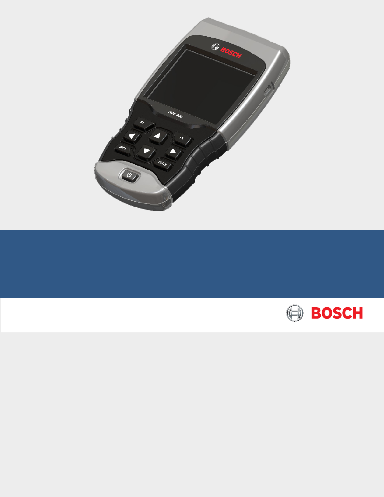
HDS 200 HD Scan Tool
for Class 4-8 Diesel, Light and Medium Vehicles
en User guide

en | 2 | User guide
| HDS 200
HD Scan Tool for Class 4-8 Diesel, Light and Medium Vehicles
Serial No: __________________________________
SW ID: _____________________________________
HW Ver: ____________________________________
Boot Ver: ___________________________________
Prod ID: ____________________________________
Board ID: ___________________________________
Burn Date: _________________________________
Record the above information about your tool. The information is available
at Main Menu --> System Setup --> Tool Information. Provide this information when contacting technical support.
If you have questions or concerns contact Technical Support:
Phone: 1-855-267-2483
E-mail: techsupport.diagnostics@us.bosch.com
The information, specifications and illustrations in this guide are based on
the latest information available. Bosch reserves the right to make changes
at any time without notice.
581618 | REV. A | 11.2017
Bosch Automotive Service Solutions Inc.

HDS 200
HD Scan Tool for Class 4-8 Diesel, Light and Medium Vehicles | User guide | 3 | en
Table of Contents
1 Safety Precautions ....................... 4
1.1 Read All Instructions ................ 4
1.2 Safety Messages ...................4
2 Important Safety Warnings and Instructions .. 4
3 Getting Started .........................7
3.1 Introduction .......................7
3.2 Download Scanning Suite ............ 7
3.3 Introduction to On-Board Diagnostics ... 7
SAE J1587/J1708 ................... 7
SAE J1939 ........................ 7
OBD II ............................7
3.4 SAE Publications ...................8
3.5 Data Link Connector (DLC) ...........8
J1939 Type 2 ....................... 8
J1708/J1587 ....................... 8
OBD II (J1962) .....................8
OBD II Data Link Connector (DLC) Pins .. 9
3.6 J1939 Diagnostic Trouble Codes .......9
3.7 J1587 Diagnostic Trouble Codes .......9
3.8 OBD II Diagnostic Trouble Codes (DTCs) 9
Powertrain Codes ...................9
Chassis Codes ......................9
Body Codes ........................ 9
Network Communication Codes ........9
4 Using the Scan Tool .....................10
4.1 The Scan Tool .....................10
4.2 Specifications ..................... 10
Dimensions .......................10
Accessories ....................... 10
Optional Accessories ...............10
4.3 Display ..........................10
Keypad ..........................11
4.4 Power ...........................11
Internal Battery Power ..............11
Vehicle Power ..................... 11
USB Power .......................11
4.5 System Setup .....................11
Changing Measurement Units ......... 11
Changing Auto-Power Off ............12
Quick Test ........................ 12
Print Header ...................... 13
Language Setup ................... 13
Long PID Names ................... 13
Pre-Trigger Setup ..................14
Tool Information ...................14
Display Test ....................... 14
Keypad Test ....................... 15
Memory Test ......................15
Program Mode ....................16
4.6 Vehicle-Specific Features ............16
Review Data ......................16
Recording ........................ 17
Print Data ........................17
4.7 Locating Data Link Connector ........18
4.8 Connect the Tool ..................18
4.9 Vehicle Selection .................. 18
5 Heavy Duty Standard Diagnostics ..........19
5.1 Read Codes ......................20
Lamp Status ......................21
Erase ............................ 21
5.2 Erase Codes ...................... 21
5.3 View Data ........................22
View Entire List .................... 23
Custom List Select ................. 23
5.4 Record Data ...................... 24
5.5 Module Information ................25
5.6 Vehicle Information ................ 26
6 OBD II Diagnostics ...................... 26
6.1 I/M Monitors (Emissions) ........... 27
6.2 Read Codes ......................28
6.3 Erase Codes ...................... 29
6.4 MIL Status ....................... 30
6.5 State OBD Check ..................30
6.6 View Data ........................31
View Entire List .................... 31
Custom List Select ................. 32
6.7 Record Data ...................... 33
6.8 View Freeze Data ..................34
6.9 Drive Cycle Monitor ................34
6.10 O2 Monitor Tests ..................35
6.11 Diagnostic Monitor Tests ............ 36
6.12 On-Board Systems ................. 37
6.13 Vehicle Information ................ 38
6.14 Modules Present .................. 40
7 Troubleshooting ........................ 41
7.1 Error Messages ...................41
7.2 Scan Tool Does Not Power Up ........ 41
7.3 Vehicle Communication Fault ........41
7.4 Operating Error or Erroneous Data .... 41
7.5 Battery Replacement ............... 41
7.6 Tool Self-Tests .................... 42
7.7 Technical Support ................. 42
8 Appendix A—Global OBD II PID Definitions ... 42
9 Appendix B—Glossary ................... 44
10 Third Party Licenses ....................51
11 Limited Warranty .......................52
Bosch Automotive Service Solutions Inc.
581618 | REV. A | 11.2017
en | 4 | User guide
| HDS 200
HD Scan Tool for Class 4-8 Diesel, Light and Medium Vehicles
1 Safety Precautions
For your safety, read this manual thoroughly before
operating your scan tool. Always refer to and follow
safety messages and test procedures provided by the
manufacturer of the vehicle or equipment being tested.
The safety messages presented below and throughout
this user’s manual are reminders to the operator to
exercise extreme care when using this test instrument.
1.1 Read All Instructions
Read and understand the user guide before operating the tool.
Read, understand, and follow all safety messages and
instructions in this manual and on the test equipment.
Safety messages in this section of the manual contain a
signal word with a three-part message and, in some
instances, an icon.
1.2 Safety Messages
Safety messages are provided to help prevent personal
injury and equipment damage. All safety messages are
introduced by a signal word. The signal word indicates
the level of the hazard in a situation. The types of safety
messages are.
DANGER
Indicates a possible hazardous situation
which, if not avoided, will result in death
or serious injury to operator or bystanders.
WARNING
Indicates a possible hazardous situation which, if not avoided, could result
in death or serious injury to operator or
bystanders.
CAUTION
Indicates a possible hazardous situation which, if not avoided, may result in
moderate or minor injury to operator or
bystanders.
IMPORTANT
Indicates a condition which, if not avoided, may result in damage to test equipment or vehicle.
2 Important Safety Warnings
and Instructions
WARNING
Risk of electric shock.
• Do not exceed voltage limits between
inputs indicated in the Specifications.
• Use extreme caution when working
with circuits that have voltage greater
than 60 volts DC or 24 volts AC.
Electric shock can cause injury.
WARNING
Risk of poisoning.
• Safety goggles and protective clothing must
be worn by the operator and any bystanders.
– Even if everyday glasses have
impact resistant lenses, they are
NOT safety glasses, and may not
provide adequate protection.
• Do not use this scan tool in environments where explosive vapors may
collect. These areas include:
– below-ground pits.
– confined areas.
– areas that are less than 18 inches
above floor.
• Use this scan tool in locations with
mechanical ventilation providing at
least 4 air changes per hour.
• Flammable fuel and vapors can ignite.
• Do not smoke, strike a match, or cause
a spark in the vicinity of the battery.
Battery gases can ignite.
• Avoid making an accidental connection
between the battery terminals. Do not place
uninsulated metal tools on the battery.
• When removing battery cables, remove
the ground cable first.
• Avoid sparks when connecting or disconnecting power leads to the battery.
• Make sure ignition is off, headlights
and other accessories are off and
vehicle doors are closed before disconnecting the battery cables.
– This also helps prevent damage to
on-board computer systems.
• Always disconnect the battery ground
connections before servicing electrical system components.
Explosion can cause injury.
581618 | REV. A | 11.2017
Bosch Automotive Service Solutions Inc.
HDS 200
HD Scan Tool for Class 4-8 Diesel, Light and Medium Vehicles | User guide | 5 | en
WARNING
Risk of poisoning.
• Use this scan tool in locations with
mechanical ventilation providing at
least 4 air changes per hour. Engine
exhaust contains odorless gas which
can be lethal.
• Route the exhaust outside while
testing with the engine running.
Poisoning can result in death or serious injury.
WARNING
Battery acid is a highly corrosive sulfuric acid.
• Safety goggles and protective gloves must be
worn by the operator and any bystanders.
– Even if your everyday glasses
have impact resistant lenses, they
are NOT safety glasses, and may
not provide adequate protection.
• Make sure someone can hear you or is
close enough to provide aid when
working near a battery.
• Have plenty of fresh water and soap nearby.
– If battery acid contacts skin,
clothing, or eyes, flush exposed
area with soap and water for 10
minutes. Seek medical help.
• Do not touch eyes while working near battery.
Battery acid can burn eyes and skin.
WARNING
Risk of fire.
• Safety goggles and protective clothing must
be worn by the operator and any bystanders.
– Even if your everyday glasses
have impact resistant lenses, they
are NOT safety glasses, and may
not provide adequate protection.
• Do not position your head directly in
front of or over the throttle body.
• Do not pour gasoline down the throttle body when cranking or running the
engine, when working with fuel delivery systems or any open fuel line.
– Engine backfire can occur when
the air cleaner is out of position.
• Do not use fuel injector cleaning solvents
when performing diagnostic testing.
• Keep cigarettes, sparks, open flame
and other sources of ignition away
from vehicle.
• Keep a dry chemical (Class B) fire
extinguisher rated for gasoline, chemical and electrical fires in work area.
Fire can cause death or serious injury.
WARNING
Risk of flying particles.
• Safety goggles and protective gloves must
be worn by the operator and any bystanders while using electrical equipment.
– Electrical equipment or rotating
engine parts can cause flying particles.
– Even if your everyday glasses
have impact resistant lenses, they
are NOT safety glasses, and may
not provide adequate protection.
Flying particles can cause eye injury.
WARNING
Risk of burns.
• Batteries can produce a short-circuit
current high enough to weld jewelry
to metal.
– Remove jewelry such as rings,
bracelets and watches before
working near batteries.
Short circuits can cause injury.
WARNING
Risk of burns.
• Do not remove radiator cap unless
engine is cold.
– Pressurized engine coolant may
be hot.
• Do not touch hot exhaust systems, manifolds, engines, radiators, sample probe.
• Wear insulated gloves when handling
hot engine components.
• Tester leads can become hot after extended
testing in close proximity to manifolds.
Hot components can cause injury.
WARNING
Risk of expelling fuel, oil vapors, hot steam,
hot toxic exhaust gases, acid, refrigerant
and other debris.
• Safety goggles and protective clothing
must be worn by the operator and any
bystanders.
– Even if your everyday glasses
have impact resistant lenses, they
are NOT safety glasses, and may
not provide adequate protection.
• Engine systems can malfunction,
expelling fuel, oil vapors, hot steam,
hot toxic exhaust gases, acid, refrigerant and other debris.
Fuel, oil vapors, hot steam, hot toxic
exhaust gases, acid, refrigerant and other
debris can cause serious injury.
Bosch Automotive Service Solutions Inc.
581618 | REV. A | 11.2017
en | 6 | User guide
| HDS 200
HD Scan Tool for Class 4-8 Diesel, Light and Medium Vehicles
P R N D L 2
WARNING
Engine compartment contains electrical
connections and hot or moving parts.
• Keep yourself, test leads, clothing and
other objects clear of electrical connections and hot or moving engine parts.
• Do not wear watches, rings, or loose
fitting clothing when working in an
engine compartment.
• Do not place tools or test equipment
on fenders or other places in engine
compartment.
• Barriers are recommended to help
identify danger zones in test area.
• Prevent personnel from walking
through test area.
Contacting electrical connections and hot
or moving parts can cause injury.
WARNING
Risk of injury.
• The scan tool should be operated by
qualified personnel only.
• Use the scan tool only as described in
the user’s manual.
• Use only manufacturer’s recommended attachments.
• Do not operate the scan tool with
damaged cables.
• Do not operate the scan tool if it has
been dropped or damaged, until examined by a qualified service representative.
Operation of the scan tool by anyone other
than qualified personnel may result in injury.
WARNING
Risk of unexpected vehicle movement.
• Block drive wheels before performing
a test with engine running.
• Unless instructed otherwise:
– set parking brake
– put gear selector in neutral for
manual transmissions
– put gear selector in park for
automatic transmissions
– disconnect release mechanism on
the automatic parking brake
release for testing and reconnect
when testing is completed.
• Do not leave a running engine unattended.
A moving vehicle can cause injury.
CAUTION
Risk of equipment or circuit damage.
• Unless specifically directed by manufacturer, make sure ignition is off before
connecting or disconnecting connectors
or any vehicle electrical terminals.
• Do not create a short between battery
terminals with a jumper wire or tools.
Improper equipment use can cause equipment or circuit damage.
CAUTION
Misdiagnosis may lead to incorrect or
improper repair and/or adjustment.
• Do not rely on erratic, questionable,
or obviously erroneous test information or results.
– If test information or results are
erratic, questionable, or obviously
erroneous, make sure all connections and data entry information
are correct and test procedures
were performed correctly.
– If test information or results are
still suspicious, do not use them
for diagnosis.
Improper repair and/or adjustment may
cause vehicle or equipment damage or
unsafe operation.
DANGER
Some vehicles are equipped with air bags.
• Follow service manual warnings when
working around air bag components
or wiring.
– If service manual instructions are
not followed, an air bag may deploy
unexpectedly, resulting in injury.
– Note an air bag can still deploy
several minutes after ignition key
is off (or even if vehicle battery is
disconnected) because of a
special energy reserve module.
An air bag opening can cause injury.
581618 | REV. A | 11.2017
Bosch Automotive Service Solutions Inc.

HDS 200
HD Scan Tool for Class 4-8 Diesel, Light and Medium Vehicles | User guide | 7 | en
3 Getting Started
3.1 Introduction
The scan tool was developed by experts in the Heavy
Duty Diesel and automotive service industry to help
diagnose vehicles and assist in troubleshooting procedures.
The scan tool monitors vehicle events and retrieves
codes from the vehicle’s control modules to help pinpoint problem areas.
All information, illustrations and specifications contained in this manual are based on the latest information
available from industry sources at the time of publication.
No warranty (expressed or implied) can be made for its
accuracy or completeness, nor is any responsibility
assumed by the manufacturer or anyone connected with
it for loss or damages suffered through reliance on any
information contained in this manual or misuse of
accompanying product. The manufacturer reserves the
right to make changes at any time to this manual or
accompanying product without obligation to notify any
person or organization of such changes.
3.2 Download Scanning Suite
• Go to https://www.boschdiagnostics.com/pro/
Bosch-HDS-200 and download the Scanning Suite
PC application.
• Scanning Suite is NOT required to operate the Scan
Tool.
• Install the downloaded Scanning Suite application
prior to connecting the Scan Tool to the PC.
• Some of the items included in Scanning Suite are:
– Tool update software
– Print Capture
• To be able to use Scanning Suite the PC must meet
the following minimum requirements:
– Microsoft Windows 7, 8, and 10.
– Adobe Acrobat Reader
– Screen Resolution of 800 x 600
– If screen resolution is 800 x 600, in Display
Properties, Settings Tab, set Font Size to Small
Fonts.
• Use Scanning Suite to determine if any updates are
available for your tool by clicking Check for Update
button.
• You can also configure the Scanning Suite Frequency
(SS Frequency) to automatically check every xx
minutes. The default frequency is 30 minutes.
• Refer to instructions provided on https://www.
boschdiagnostics.com/pro/Bosch-HDS-200 for how
to install Scanning Suite and Tool updates.
3.3 Introduction to On-Board Diagnostics
SAE J1587/J1708
SAE J1587 is a diagnostic protocol standard developed
by the Society of Automotive Engineers (SAE) for heavyduty and most medium-duty vehicles built after 1985. Up
to 1995, individual OEMs used their own connectors.
From 1996 to 2001, the 6-pin Deutsch was standard.
Beginning in 2001, most OEMs converted to the 9-pin
Deutsch. Some OEMs still use the 6-pin Deutsch.
SAE J1708 is an SAE physical specification developed
for heavy duty vehi cles (trucks and busses). The protocol promoted a standard for serial communication
between modules with microcontrollers. J1708
describes the physical and data link layer. Almost always
used in conjunction with the application layer protocol
SAE J1587.
SAE J1939
In the early 90’s, the SAE Truck and Bus Control and
Communications Sub-committee started the development of a CAN-based application pro file for in-vehicle
communication in trucks. In 1998, the SAE published the
J1939 set of specifications. A J1939 network connects
electronic control units (ECU) within a truck and trailer
system. The J1939 specification - with its engine, transmission, and brake message definitions - is dedicated to
diesel engine applications.
SAE J1939 has been adopted widely by diesel engine
manufacturers. One driving force behind this is the
increasing adoption of the engine Elec tronic Control
Unit (ECU), which provides one method of controlling
exhaust gas emissions within US and European standards. Consequently, SAE J1939 can now be found in a
range of diesel-powered applications: vehicles (on- and
off-road), marine propulsion, power generation, and
industrial pumping.
OBD II
On-Board Diagnostics version II (OBD II) is a system that
the Society of Automotive Engineers (SAE) developed to
standardize automotive electronic diagnosis.
Beginning in 1996, most new vehicles sold in the United
States were fully OBD II compliant.
Technicians can now use the same tool to test any OBD
II compliant vehicle without special adapters. SAE established guidelines that provide:
• A universal OBD II data link connector, called the
DLC, with dedicated pin assignments.
• Diagnostics with vehicle modules involved in emissions controls such as ECM/PCM & transmission.
• A standard location for the DLC, visible under the
dash on driver’s side.
• A standard list of diagnostic trouble codes (DTCs)
used by all manufacturers.
• A standard list of parameter identification (PID) data
used by all manufacturers.
Bosch Automotive Service Solutions Inc.
581618 | REV. A | 11.2017
en | 8 | User guide
| HDS 200
HD Scan Tool for Class 4-8 Diesel, Light and Medium Vehicles
• Ability for vehicle systems to record operating conditions when a fault occurs.
• Expanded diagnostic capabilities that records a
code whenever a condition occurs that affects
vehicle emissions.
• Ability to clear stored codes from the vehicle’s
memory with a scan tool.
3.4 SAE Publications
SAE has published hundreds of pages of text defining a
standard communication protocol that establishes hardware, software, and circuit parameters of OBD II systems. Unfortunately, vehicle manufacturers have different interpretations of this standard communications
protocol. As a result, the generic OBD II communications
scheme varies, depending on the vehicle. SAE publishes
recommendations, not laws, but the Environmental
Protection Agency (EPA) and California Air Resources
Board (CARB) made many of SAE’s recommendations
legal requirements that vehicle manufacturers were
required to phase in over a three-year period. Beginning
in 1994, vehicles with a new engine management computer (about 10% of each manufacturers fleet) were supposed to comply with OBD II standards. For 1995, OBD
II systems were to appear on about 40% of the new
vehicles sold in the United States. Some of the 19941995 OBD II systems were not fully compliant, so the
Government granted waivers to give manufacturers time
to fine-tune their systems. Beginning in 1996, most of
the new vehicles sold in the United States were fully
OBD II compliant.
3.5 Data Link Connector (DLC)
The data link connector (DLC) allows the scan tool to
communicate with the vehicle’s computer(s). Use the
proper DLC adapter cable to connect the scan tool to
the vehicle. Also, the vehicle’s DLC may be found in
several different places and have many different configurations.
IMPORTANT
Power to the tool generally comes from
the vehicle. If the tool does not power-up,
use the included cigarette lighter cable
(7-0135) to power-up the tool.
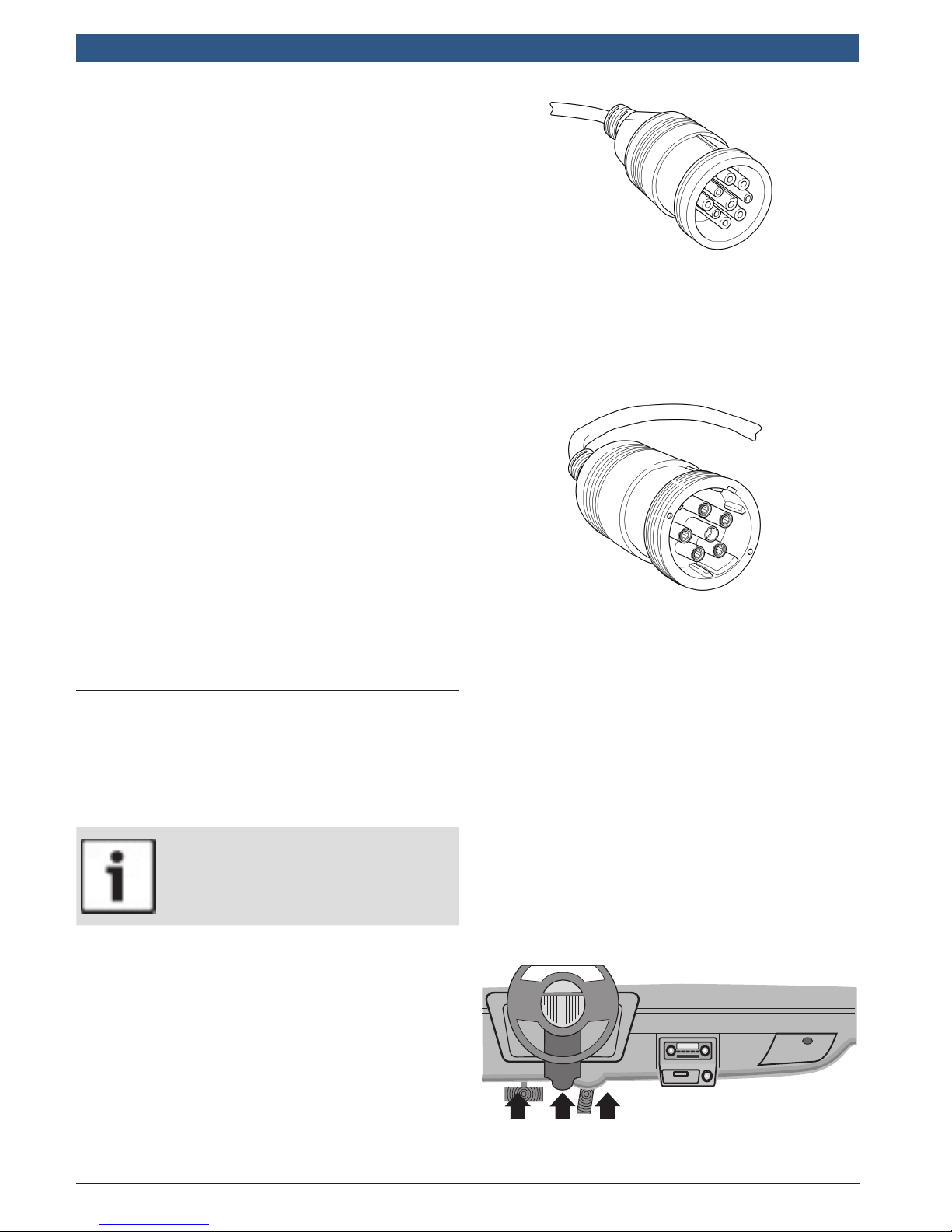
J1939 Type 2
The J1939 Type 2 is a round 9-pin green DLC adapter
cable (1699200242). This cable will work on trucks with
older J1939 Type 1 and new J1939 Type 2 DLCs.
The vehicle DLC is generally mounted inside the cab.
For on road heavy trucks, the connector should be
mounted on the driver side. For busses, the vehicle DLC
should be mounted within reach of the operators seat.
Attach the 9-pin green adapter cable (1699200242) to
the extender cable (7-0137) (both supplied with the
scan tool) to connect the tool.
J1708/J1587
The J1708/J1587 connector is a round 6-pin gray DLC
adapter cable (1699200241).
Attach the 6-pin grey adapter cable (1699200241) to the
extender cable (7-0137) (both supplied with the scan
tool) to connect the tool.
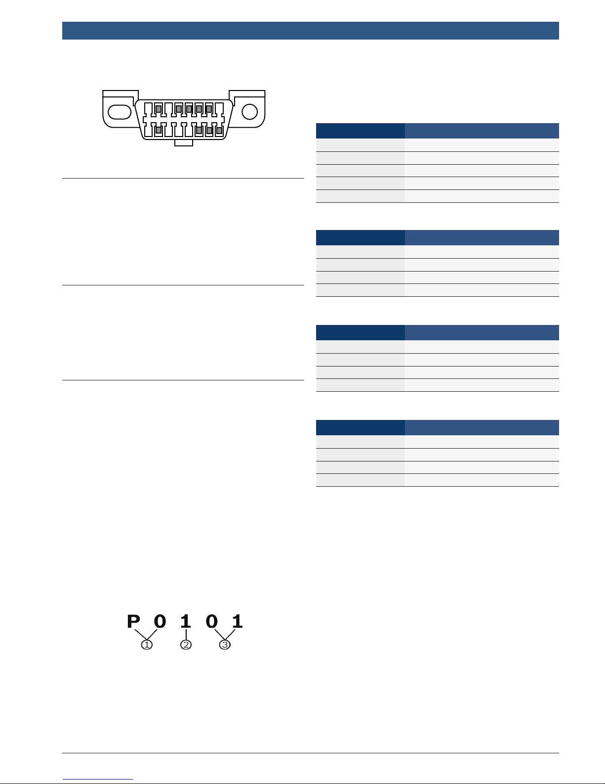
OBD II (J1962)
Beginning in 1996, vehicles sold in the United States use
the J1962 (OBD II) DLC, a term taken from a physical
and electrical specification number assigned by the SAE
(J1962). The DLC should be located under the dashboard on the driver’s side of the vehicle. If the DLC is
not located under the dashboard as stated, a decal
describing its location should be attached to the dashboard in the area the DLC should have been located. For
more information on OBD II connectors, go to
http://www.obdclearinghouse.com.
Because the OBD II J1962 connector has power and
ground, you only need a single cable connection to the
tool for both power and vehicle communications. Attach
the OBD II adapter cable (1699200243) to the extender
cable (7-0137) (both supplied with the scan tool), to
connect the tool. Certain pins in the connector are
reserved.
581618 | REV. A | 11.2017
Bosch Automotive Service Solutions Inc.
HDS 200
9 16
HD Scan Tool for Class 4-8 Diesel, Light and Medium Vehicles | User guide | 9 | en
OBD II Data Link Connector (DLC) Pins
1 8
3.6 J1939 Diagnostic Trouble Codes
J1939 DTCs are made up of a Suspect Parameter Number (SPN) and the Failure Mode Identifier (FMI). The
SPN identifies the failed component or system. The FMI
identifies the type of failure.
J1939 defines a standard set of DTCs. SAE reserves
SPNs 0 to 516095. SPNs 516096 to 524287 are
reserved for the manufacturer.
3.7 J1587 Diagnostic Trouble Codes
J1587 DTCs are made up of either a Parameter Identification number (PID) or a Subsystem Identification
number (SID). It is also made up of a Failure Mode
Identifier (FMI). The SID or PID identifies the failed
component or system. The FMI identifies the type of
failure.
3.8 OBD II Diagnostic Trouble Codes
(DTCs)
J2012 and ISO 15031-6 are standards for all DTCs,
established by the SAE, International Organization for
Standardization (ISO) and other governing bodies.
• Codes and definitions assigned by these specifications are known as Generic OBD II codes.
• OBD II requires compliance to these standards for
all cars, light trucks, APVs, MPVs, and SUVs sold in
the United States.
• Codes not reserved by the SAE are reserved for the
manufacturer and referred to as Manufacturer Specific Codes.
DTCs are used to help determine the cause of a problem
or problems with a vehicle.
• DTCs consist of a five-digit alphanumeric code.
• The DTCs format and general code types are shown
below.
Example:
P0101 = Mass or volume air flow cir cuit range/perfor-
mance problem
Powertrain Codes
Code Type
P0xxx Generic (SAE)
P1xxx Manufacturer specific
P2xxx Generic (SAE)
P30xx–P33xx Manufacturer specific
P34xx–P39xx Generic (SAE)
Chassis Codes
Code Type
C0xxx Generic (SAE)
C1xxx Manufacturer specific
C2xxx Manufacturer specific
C3xxx Generic (SAE)
Body Codes
Code Type
B0xxx Generic (SAE)
B1xxx Manufacturer specific
B2xxx Manufacturer specific
B3xxx Generic (SAE)
Network Communication Codes
Code Type
U0xxx Generic (SAE)
U1xxx Manufacturer specific
U2xxx Manufacturer specific
U3xxx Generic (SAE)
1. Bx = Body
Cx = Chassis
Px = Powertrain
Ux = Network communication
x = 0, 1, 2, or 3
2. Vehicle specific system
3. Specific fault designation
Bosch Automotive Service Solutions Inc.
581618 | REV. A | 11.2017
en | 10 | User guide
| HDS 200
HD Scan Tool for Class 4-8 Diesel, Light and Medium Vehicles
4 Using the Scan Tool
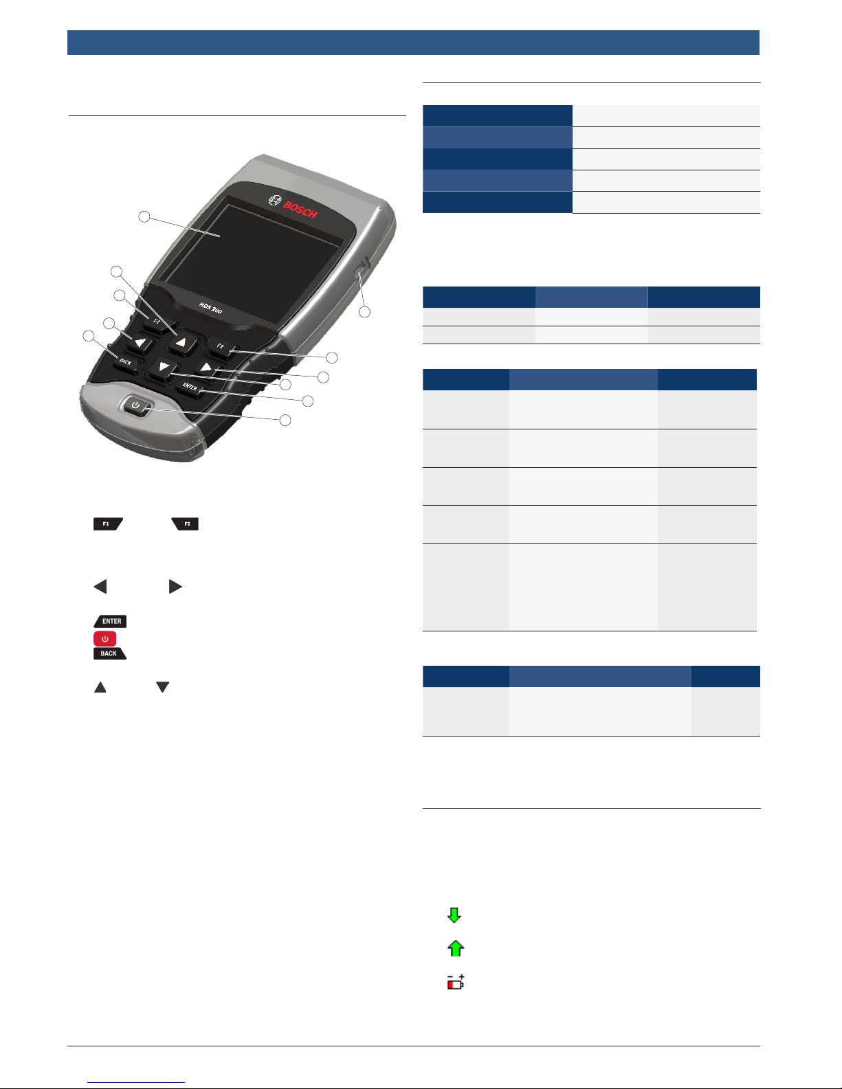
4.1 The Scan Tool
8
7
2
3
6
3
7
4
5
1. USB port - provides USB connection for the computer.
2. F1 and F2 keys are used to perform the
specified action on the display directly above the
key. If nothing appears on the display directly above
the F1 and F2 keys, then the keys are inactive.
3. LEFT and RIGHT arrow keys - selects YES or
NO and selects data parameters for custom data list.
4. ENTER key - selects displayed items.
5. ON/OFF key - turns power ON or OFF.
6. BACK key - goes to the previous screen or
level.
7. UP and DOWN arrow keys - moves selection up
or down.
8. LCD display (color, backlit, QVGA resolution)
9. DLC cable (not shown) - provides connection for
vehicle interface.
10. Serial Number Plate (not shown) - Located inside
battery compartment, provides serial number of
scan tool.
11. Battery Compartment (on back; not shown) - provides power to the scan tool when reprogramming
from a personal computer or off-vehicle reviewing of
codes and printing.
12. 12V Power Jack (not shown) - provides power to
scan tool when scan tool is conneced to certain
Heavy Duty vehicles.
1
2
4.2 Specifications
Display Color, backlit, QVGA resolution
Operating Temperature 0 to 50°C (32 to 122°F)
Storage Temperature -20 to 70°C (-4 to 158°F)
Internal Power
4-AAA Batteries
External Power 7 to 16 Volts
A minimum of 8.0 V is required for most control modules
to operate properly in a vehicle.
Dimensions
Height Width Depth
7 inches 3.75 inches 1.125 inches
178 mm 95 mm 29 mm
Accessories
Part Description Part No.
Extender
Cable
OBD II
Cable
Cigarette
Lighter
Cable
9-pin
Deutsch
Cable
6-Pin
Deutsch
Cable
USB Cable
Cable used to connect
vehicle specific adapter
cables to scan tool
Communicates
between vehicle and
tool
Cable used to power
scan tool from cigarette
lighter.
7-0137
1699200243
7-0135
Refer to page 8 1699200242
Refer to page 8 1699200241
Cable used to update
scan tool firmware and
print data to Scanning
Suite
0038-000-3430
Optional Accessories
Part Description Part No.
Battery Clip
Y Adapter
Cable
Adapter that allows the
Cigarette Lighter Cable to
connect directly to vehicle
battery cables
7-0136
Replacement parts are available from the manufacturer
by contacting customer service at 1-855-267-2483 (8:006:00 EST Monday-Friday).
4.3 Display
The display has a large viewing area for displaying messages, instructions, and diagnostic information.
The back-lit liquid crystal display (LCD) is a QVGA pixel
display. Display icons used to help operate the scan tool
are:
• Indicates additional information is available by
scrolling down.
• Indicates additional information is available by
scrolling up.
• Indicates the internal batteries need replaced or
are not installed.
581618 | REV. A | 11.2017
Bosch Automotive Service Solutions Inc.
HDS 200
HD Scan Tool for Class 4-8 Diesel, Light and Medium Vehicles | User guide | 11 | en
• √ Indicates selected items in a data list or that data
is available for items on the Review Data and Print
Data Menu.
• Indicates graphical viewing of data items is
available in View Data and when playing back previously recorded data.
Keypad
The keypad is used to move through the different menus
of the scan tool. The scan tool’s software is designed for
ease in operating and navigating through menus.
CAUTION
Do not use solvents such as alcohol to clean
keypad or display. Use a mild nonabrasive
detergent and a soft, cotton cloth.
CAUTION
Do not soak keypad as water might find
its way inside the scan tool.
4.4 Power
Internal Battery Power
• Battery power is not required to use tool.
• Press and hold ON/OFF key for at least 1 second to turn ON scan tool.
• The scan tool will autmatically turn OFF after a
user-selectable period of inactivity when powered
from the internal batteries. The default is 2 minutes.
• When powered from the internal batteries, the scan
tool will dim display backlighting.
• The scan tool must be attached to the vehicle to
perform diagnostic functions. The scan tool disables
the diagnostic functions when powered from the
internal batteries.
• Each time the scan tool is powered up, voltage of
the internal battery is checked. If voltage is low, the
Low Battery symbol ( ) displays on screen.
Replace the battery using instruction provided in
Battery Replacement.
CAUTION
If the scan tool will not be used for an
extended period of time, remove the
batteries to prevent battery leakage from
damaging the battery compartment.
Vehicle Power
When the scan tool is connected to the vehicle’s DLC,
the tool is powered by the vehicle and will automatically
turn on once connected. If you use the cigarette lighter
adapter cable, be aware that some vehicle cigarette
lighters are not powered when the ignition is in the OFF
position. Therefore, you may wish to use the optional
battery clip adapters (7-0136).
USB Power
When the tool is connected to a PC via a USB cable, the
tool will automatically power up. Refer to “7.2 Scan
Tool Does Not Power Up” on page 41 if there are
problems.
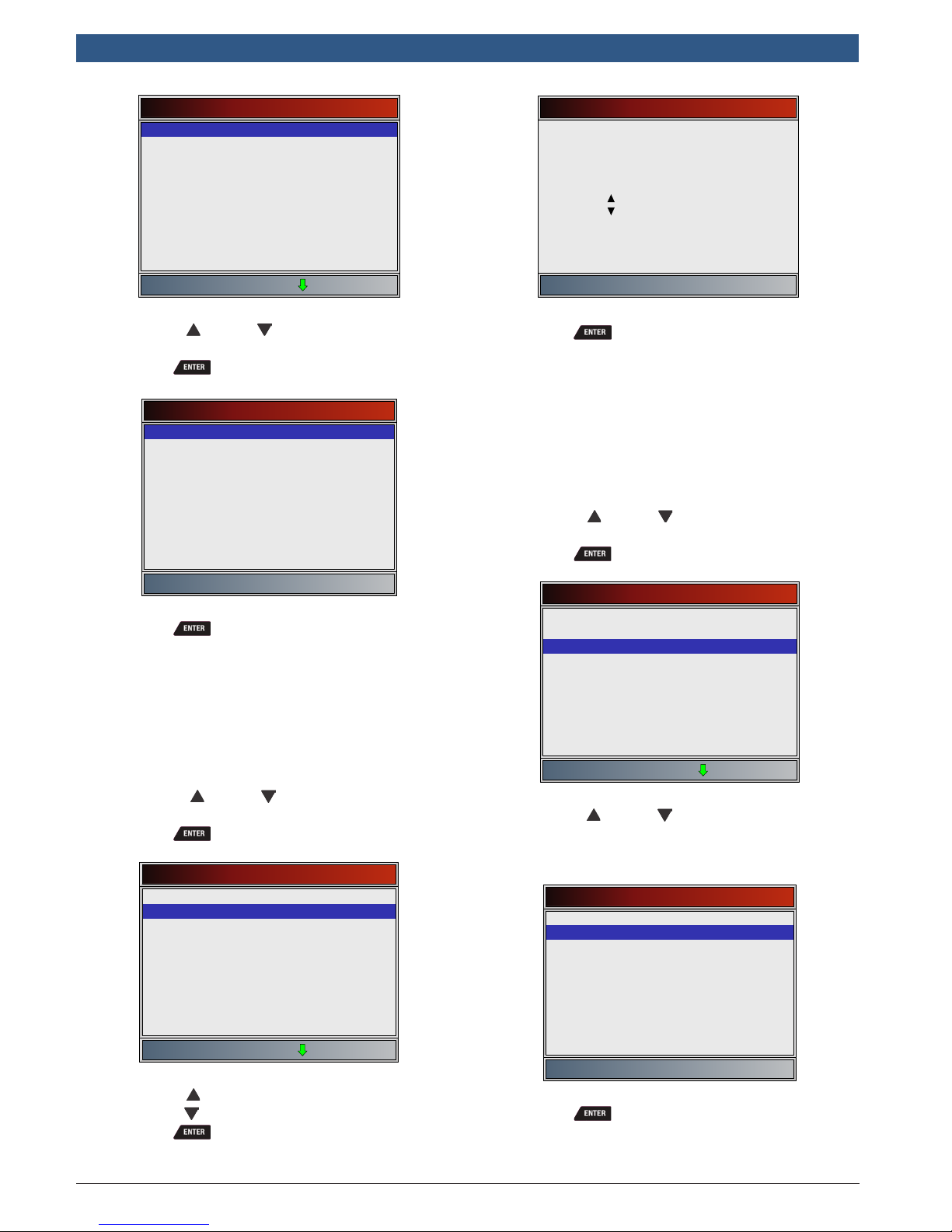
4.5 System Setup
System Setup allows:
• Measurement units to be changed.
• Auto-Power off time to be changed.
• Printer Header to be turned ON or OFF.
• Scan tool information to be viewed.
• Display to be checked.
• Operation of the keypad to be checked.
• Memory of the tool to be checked.
• Scan tool to be upgraded.
• Language to be changed.
• Quick Test to be turned ON, OFF, or set to the
desired method.
• Long PID names to be turned ON or OFF.
• Change the number of Pre-Trigger frames when
recording data.
From the Main Menu, Heavy Duty Standard menu, HD
OBD, or Global Automotive OBDII menu:
1. Select System Setup.
• Use the UP and DOWN keys until System
Setup is highlighted.
• Press .
Main Menu
HD SAE (J1708/J1587, J1939)
HD OBD (ISO 15765-4)
Global Automotive OBDII
Review Data
Print Data
System Setup
Changing Measurement Units
English is the default measurement unit. Measurement
units can be changed in View and Record Data.
From System Setup menu:
1. Select English/Metric.
• Use the UP and DOWN keys until English/
Metric is highlighted.
• Press .
Bosch Automotive Service Solutions Inc.
581618 | REV. A | 11.2017
en | 12 | User guide
| HDS 200
HD Scan Tool for Class 4-8 Diesel, Light and Medium Vehicles
System Setup
English/Metric
Auto-Power Off
Quick Test
Print Header
Language Setup
Long PID Names
Pre-Trigger Setup
Tool Information
Display Test
2. Select desired measurement unit.
• Use the UP and DOWN keys until the
desired unit is highlighted.
• Press .
Measurement Units
English
Metric
Auto-Power Off
2 minute(s)
Increase time
Decrease time
Press ENTER to continue
3. Save Auto-Power Off time.
• Press .
Quick Test
Quick Test is a feature of the tool that occurs the first
time the tool establishes communication with the vehicle after vehicle selection. Quick Test will display the
results of I/M Monitors (Global Automotive OBDII and
HD OBDII only) and Read Codes.
From System Setup menu:
1. Select Quick Test.
• Use the UP and DOWN keys until Quick
Tes t is highlighted.
• Press .
3. Save measurement setting.
• Press .
Changing Auto-Power Off
The Auto-Power Off feature allows the tool to turn off
automatically after a selected amount of time when tool
is not being used. The Auto-Power Off feature will only
turn the tool off when it is operating on battery power.
From System Setup menu:
1. Select Auto-Power Off.
• Use the UP and DOWN keys until Auto-
Power Off is highlighted.
• Press .
System Setup
English/Metric
Auto-Power Off
Quick Test
Print Header
Language Setup
Long PID Names
Pre-Trigger Setup
Tool Information
Display Test
System Setup
English/Metric
Auto-Power Off
Quick Test
Print Header
Language Setup
Long PID Names
Pre-Trigger Setup
Tool Information
Display Test
2. Select desired Quick Test choice.
• Use the UP and DOWN keys until desired
choice is highlighted.
• Select Read All Codes to view results of all
codes. This selection is enabled by default.
Quick Test
Disabled
Read All Codes
2. Increase or Decrease Auto-Power Off time.
• Use the UP key to increase time.
• Use the DOWN key to decrease time.
• Press .
581618 | REV. A | 11.2017
3. Save Quick Test setting.
• Press .
Bosch Automotive Service Solutions Inc.
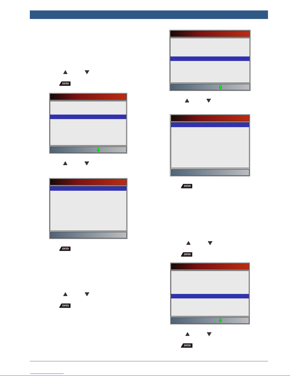
HDS 200
System Setup
English/Metric
Auto-Power Off
Quick Test
Print Header
Language Setup
Long PID Names
Pre-Trigger Setup
Tool Information
Display Test
HD Scan Tool for Class 4-8 Diesel, Light and Medium Vehicles | User guide | 13 | en
Print Header
Print Header selection allows the user to turn off the
scan tool printing the currently-selected vehicle prior to
the retrieved vehicle data when selecting items from the
Print Data menu.
From System Setup menu:
1. Select Print Header.
• Use the UP and DOWN keys until Print
Header is highlighted.
• Press .
System Setup
English/Metric
Auto-Power Off
Quick Test
Print Header
Language Setup
Long PID Names
Pre-Trigger Setup
Tool Information
Display Test
2. Select desired Print Header choice.
• Use the UP and DOWN keys until desired
choice is highlighted.
Print Header
ON
OFF
3. Save Print Header setting.
• Press .
Language Setup
Language Setup selection allows the user to change the
language used by the tool. English is the default language.
From System Setup menu:
1. Select Language Setup.
• Use the UP and DOWN keys until Lan-
guage Setup is highlighted.
• Press .
2. Select desired Language Setup choice.
• Use the UP and DOWN keys until the
desired language is highlighted.
Language Setup
English
Español
Francais
3. Save Language Setup setting.
• Press .
NOTE: When Spanish or French translation is not known,
English will be shown.
Long PID Names
Long PID Names allows the user to enable/disable the tool
scrolling the complete PID name on the bottom line of the
display while viewing Live Data or viewing Freeze Data.
From System Setup menu:
1. Select Long PID Names.
• Use the UP and DOWN keys until Long
PID Names is highlighted.
• Press .
System Setup
English/Metric
Auto-Power Off
Quick Test
Print Header
Language Setup
Long PID Names
Pre-Trigger Setup
Tool Information
Display Test
Bosch Automotive Service Solutions Inc.
2. Select ON or OFF.
• Use the UP and DOWN keys until the
desired option is highlighted.
• Press .
581618 | REV. A | 11.2017
en | 14 | User guide
| HDS 200
HD Scan Tool for Class 4-8 Diesel, Light and Medium Vehicles
Long PID Names
ON
OFF
3. Save Long PID Names setting.
• Press .
Pre-Trigger Setup
This function is used to configure how many Pre-Trigger
frames are stored prior to beginning a recording. PreTrigger frames are the negative frames when you are
playing back a recording.
From System Setup screen:
1. Select Pre-Trigger Setup.
• Use the UP and DOWN keys until Pre-
Trigger Setup is highlighted.
• Press .
System Setup
English/Metric
Auto-Power Off
Quick Test
Print Header
Language Setup
Long PID Names
Pre-Trigger Setup
Tool Information
Display Test
2. Increase or Decrease Pre-Trigger Frames.
• Use the UP key to increase frames.
• Use the DOWN key to decrease frames.
• Press .
Tool Information
Tool Information allows the user to view specific tool information that may be needed when contacting customer
service.
From System Setup menu:
1. Select Tool Information.
• Use the UP and DOWN keys until Tool
Information is highlighted.
• Press .
System Setup
English/Metric
Auto-Power Off
Quick Test
Print Header
Language Setup
Long PID Names
Pre-Trigger Setup
Tool Information
Display Test
2. View information.
• Serial Number (Serial No:)
• Software ID (SW ID:)
• Hardware Version (HW Ver:)
• Boot Version (Boot Ver:)
• Product ID (Prod ID:)
• Board ID (Board ID:)
• Burn Date (Burn Date:)
• Burn Location (Burn Loc:)
Tool Information
Serial No
SW ID
HW Ver
Boot Ver
Prod ID
Board ID
Burn Date
Burn Loc 04
1284168
5126
01
02
21
33
12/04/14
Pre-Trigger Frames
5 frame(s)
Increase frame
Decrease frame
Press ENTER to continue
3. Save Pre-Trigger frames setting.
• Press .
581618 | REV. A | 11.2017
3. Record Tool Information.
• Space is provided inside the front cover of this
manual to write down the scan tool information.
4. Return to System Setup menu.
• Press
or
• Press .
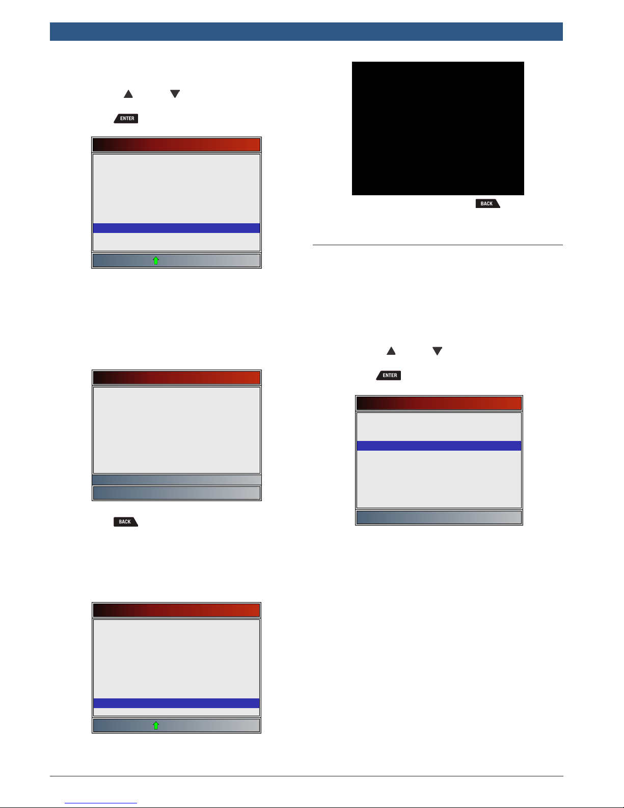
Display Test
The Display Test is used to check the display. The test fills
every pixel of the display with a solid color.
From System Setup menu:
1. Select Display Test.
• Use the UP and DOWN keys until Display
Tes t is highlighted.
• Press .
Bosch Automotive Service Solutions Inc.
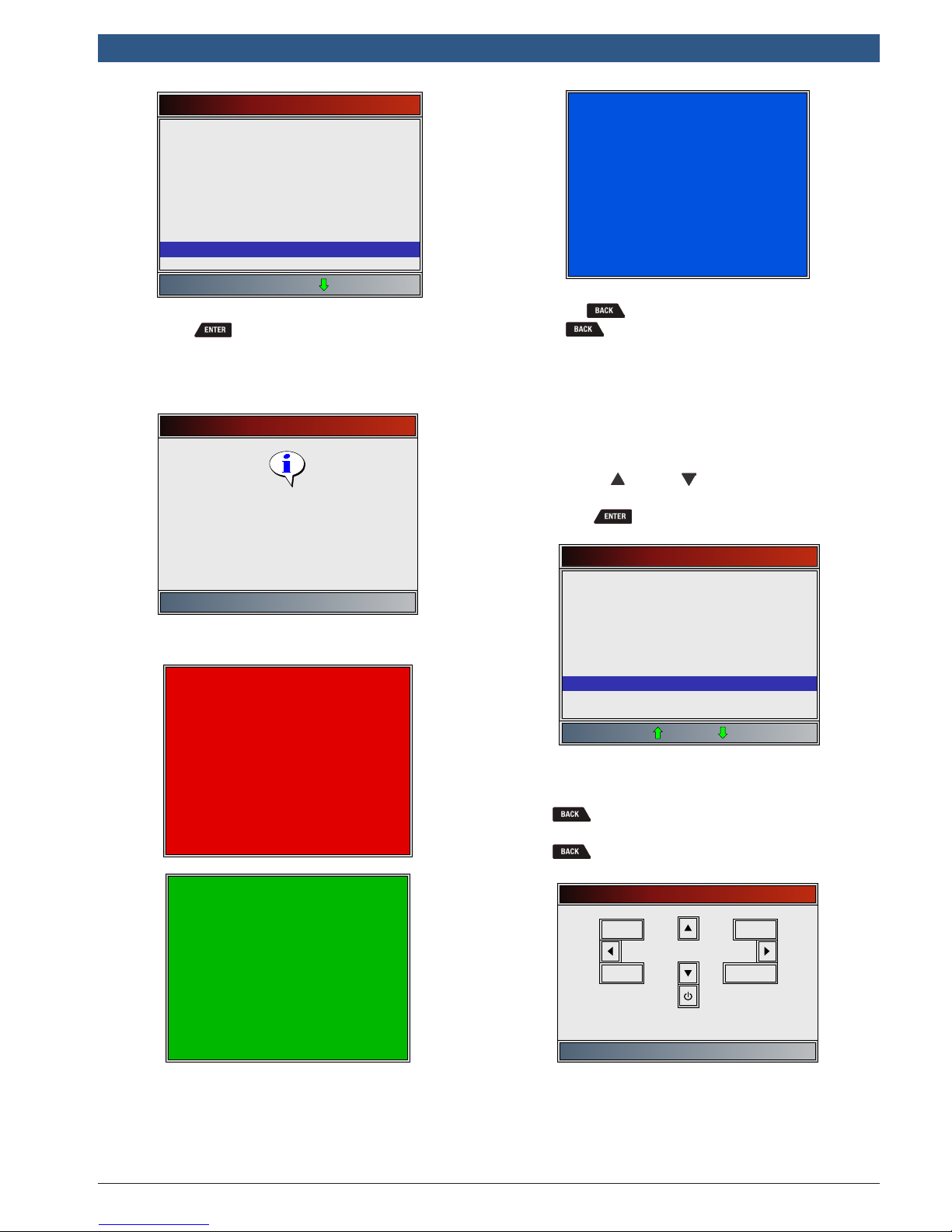
HDS 200
Keypad Test
Press BACK to exit
BACK
ENTER
F1
F2
System Setup
English/Metric
Auto-Power Off
Quick Test
Print Header
Language Setup
Long PID Names
Pre-Trigger Setup
Tool Information
Display Test
2. Start Display Test.
• Press .
3. Look for missing spots.
• The first screen displayed says, “Check for
missing spots in the display.”
Display Test
Check for spots in the
display
Press BACK to exit
• Solid red, green, and blue screens are displayed.
HD Scan Tool for Class 4-8 Diesel, Light and Medium Vehicles | User guide | 15 | en
• These four screens will continue in succession
until is pressed.
4. Press to exit the test and return to the System
Setup menu.
Keypad Test
The Keypad Test is used to verify that the keys are
working correctly.
From System Setup menu:
1. Select Keypad Test.
• Use the UP and DOWN keys until Keypad
Tes t is highlighted.
• Press .
System Setup
Quick Test
Print Header
Language Setup
Long PID Names
Pre-Trigger Setup
Tool Information
Display Test
Keypad Test
Memory Test
Bosch Automotive Service Solutions Inc.
2. Press a key.
• Key name or scroll direction should inverse
colors on display.
• will return the tool to the System Setup
screen. If System Setup screen does not return,
is not working correctly.
Memory Test
The Memory Test will test RAM and Flash ROM. Run the
Memory Test if the tool has trouble:
• Playing back recorded data.
• Displaying trouble code definitions.
581618 | REV. A | 11.2017
en | 16 | User guide
| HDS 200
HD Scan Tool for Class 4-8 Diesel, Light and Medium Vehicles
From System Setup menu:
1. Select Memory Test.
• Use the UP and DOWN keys until Memory
Tes t is highlighted.
• Press .
System Setup
Print Header
Language Setup
Long PID Names
Pre-Trigger Setup
Tool Information
Display Test
Keypad Test
Memory Test
Program Mode
• Memory Test may take several minutes to complete.
• Memory Test results display:
– If no problems were detected, then “Pass”
is displayed.
– If RAM fails, an error message is shown.
– If FLASH fails, a checksum is shown.
Memory Test
INT RAM
INT FLASH
Press BACK to exit
Passed
10ca
PROGRAM MODE
See User Manual
Connect Tool to PC
with USB Cable
• If the Program Mode is entered, is not operational. The tool must be powered off to exit Program
Mode and then restarted to continue.
4.6 Vehicle-Specific Features
Review Data
The Review Data function allows the user to view the
information from the previous vehicle tested. The scan
tool can be powered from vehicle, battery power or PC
using USB to use the Review Data function.
1. Select Review Data.
• Use the UP and DOWN keys until Review
Data is highlighted.
• Press .
Main Menu
HD SAE (J1708/J1587, J1939)
HD OBD (ISO 15765-4)
Global Automotive OBDII
Review Data
Print Data
System Setup
2. Return to System Setup menu.
• Press .
Program Mode
The Program Mode is used for updating the scan tool.
Instructions are provided with upgrades. Refer to “3.2
Download Scanning Suite” on page 7.
System Setup
Print Header
Language Setup
Long PID Names
Pre-Trigger Setup
Tool Information
Display Test
Keypad Test
Memory Test
Program Mode
581618 | REV. A | 11.2017
2. Select item whose data you wish to review.
• The Review Data menu shows a checkmark next
to the item(s) that has data.
• If there is not a checkmark next to the item, then
this item can’t be selected until the appropriate
function is run from the Heavy Duty Standard
menu, HD OBD menu or Global Automotive
OBDII menu.
• Only one function, Recording, needs detailed
instructions.
Bosch Automotive Service Solutions Inc.
 Loading...