

Bosch HDH183, DDH183 Operating And Safety Instructions Manual
IMPORTANT: IMPORTANT : IMPORTANTE:
Read Before Using Lire avant usage Leer antes de usar
For English Version Version française Versión en español
See page 2 Voir page 16 Ver la página 30
Operating/Safety Instructions
Consignes de fonctionnement/sécurité
Instrucciones de funcionamiento y seguridad
1-877-BOSCH99 (1-877-267-2499) www.boschtools.com
Call Toll Free for
Consumer Information
& Service Locations
Pour obtenir des informations
et les adresses de nos centres
de service après-vente,
appelez ce numéro gratuit
Llame gratis para
obtener información
para el consumidor y
ubicaciones de servicio
HDH183
DDH183
2610042685 DDH183 HDH183.qxp_DDH - HDH 1/22/16 12:26 PM Page 1

-2-
Work area safety
Keep work area clean and well lit. Cluttered
or dark areas invite accidents.
Do not operate power tools in explosive
atmospheres, such as in the presence of
flammable liquids, gases or dust. Power
tools create sparks which may ignite the dust
or fumes.
Keep children and bystanders away while
operating a power tool. Distractions can
cause you to lose control.
Electrical safety
Power tool plugs must match the outlet.
Never modify the plug in any way. Do not
use a n y adapter pl u gs with eart h e d
(grounded) power tools. Unmodified plugs
and matching outlets will reduce risk of electric
shock.
Avoid body contact with earthed or grounded
surfaces such as pipes, radiators, ranges
and refrigerators. There is an increased risk
of electric shock if your body is earthed or
grounded.
Do not expose power tools to rain or wet
conditions. Water entering a power tool will
increase the risk of electric shock.
Do not abuse the cord. Never use the cord
for carrying, pulling or unplugging the power
tool. Keep cord away from heat, oil, sharp
edges or moving parts. Damaged or entangled
cords increase the risk of electric shock.
When operating a power tool outdoors,
use an extension cord suitable for outdoor
use. Use of a cord suitable for outdoor use
reduces the risk of electric shock.
If operating a power tool in a damp location
is unavoidable, use a Ground Fault Circuit
Interrupter (GFCI) protected supply. Use of
an GFCI reduces the risk of electric shock.
Personal safety
Stay alert, watch what you are doing and
us e common sense whe n operating a
power tool. Do not use a power tool while
you are tired or under the influence of drugs,
alcohol or medication. A moment of inattention
while operating power tools may result in
serious personal injury.
Use personal protective equipment. Always
wear eye protection. Protective equipment
Read all safety warnings and all instructions. Failure to follow the
warnings and instructions may result in electric shock, fire and/or serious
injury.
SAVE ALL WARNINGS AND INSTRUCTIONS FOR FUTURE REFERENCE
The term “power tool” in the warnings refers to your mains-operated (corded) power tool or
battery-operated (cordless) power tool.
General Power Tool Safety Warnings
Safety Symbols
The definitions below describe the level of severity for each signal word. Please read the manual
and pay attention to these symbols.
!
This is the safety alert symbol. It is used to alert you to potential
personal injury hazards. Obey all safety messages that follow this
symbol to avoid possible injury or death.
DANGER indicates a hazardous situation which, if not avoided, will
result in death or serious injury.
WARNING indicates a hazardous situation which, if not avoided, will
result in death or serious injury.
CAUTION, used with the safety alert symbol, indicates a hazardous
situation which, if not avoided, will result in minor or moderate injury.
2610042685 DDH183 HDH183.qxp_DDH - HDH 1/22/16 12:26 PM Page 2

Wear ear protectors when impact drilling.
Exposure to noise can cause hearing loss.
Use auxiliary handle(s) if supplied with the
tool. Loss of control can cause personal injury.
Hold power tool by insulated gripping
surfaces, when performing an operation
where the cutting accessory may contact
hidden wiring. Cutting accessory contacting a
"live" wire may make exposed metal parts of
th e po wer tool "liv e" a nd could give the
operator an electric shock.
Safety Rules for Cordless Hammer Drills
-3-
such as dust mask, non-skid safety shoes, hard
h
at, or hearing protection used for appropriate
conditions will reduce personal injuries.
Prevent unintentional starting. Ensure the
sw itch is in the off-position before
connecting to power source and / or battery
pa ck, picking up or carrying th e tool.
Carrying power tools with your finger on the
switch or energizing power tools that have the
switch on invites accidents.
Remove any adjusting key or wrench before
turning the power tool on. A wrench or a
key left attached to a rotating part of the power
tool may result in personal injury.
Do not overreach. Keep proper footing and
balance at all times. This enables better
con trol of th e powe r too l in unexpe cted
situations.
Dress properly. Do not wear loose clothing
or jewelry. Keep your hair, clothing and
gloves away from moving parts. Loose
clothes, jewelry or long hair can be caught in
moving parts.
If devices are provided for the connection
of dust extraction and collection facilities,
ensure these are connected and properly
used. Use of dust collection can reduce dust-
related hazards.
Power tool use and care
Do not forc e the p ower to ol. Use the
correct power tool for your application. The
correct power tool will do the job better and
safer at the rate for which it was designed.
Do not use the power tool if the switch does
not turn it on and off. Any power tool that
can n o t b e c ontrolled with the swit c h i s
dangerous and must be repaired.
Disconnect the plug from the power source
and/or the battery pack from the power tool
before making any adjustments, changing
accessories, or storing power tools. Such
preventive safety measures reduce the risk of
starting the power tool accidentally.
Store idle power tools out of the reach of
children and do not allow persons unfamiliar
with the power tool or these instructions to
operate the power tool. Power tools are
dangerous in the hands of untrained users.
Maintain power tools. Check for misalignment
or binding of moving parts, breakage of
parts and any other condition that may
affect the power tool’s operation. If damaged,
have the power tool repaired before use.
Man y ac c idents are caused by poo r l y
maintained power tools.
Keep cutting tools sharp and clean. Properly
maintained cutting tools with sharp cutting
edges are less likely to bind and are easier to
control.
Use the power tool, accessories and tool
bits etc. in accordance with these instructions,
taking into account the working conditions
and the work to be performed. Use of the
power tool for operations different from those
intended could result in a hazardous situation.
Battery tool use and care
Recharge only with the charger specified
by the man ufacturer. A ch arge r th at i s
suitable for one type of battery pack may
create a risk of fire when used with another
battery pack.
Use power tools only with specifically
designated battery packs. Use of any other
battery packs may create a risk of injury and
fire.
When battery pack is not in use, keep it
away from other metal objects like paper
clips, coins, keys, nails, screws, or other
small metal o b j e c t s t h a t c a n make a
connection from one terminal to another.
Shorting the battery terminals together may
cause burns or a fire.
Under abusive conditions, liquid may be
ejected from the battery; avoid contact. If
contact accidentally occurs, flush with
water. If liquid contacts eyes, additionally
seek medical help. Liquid ejected from the
battery may cause irritation or burns.
Service
Have your power tool serviced by a qualified
rep a i r per s o n usi n g only identi c al
replacement parts. This will ensure that the
safety of the power tool is maintained.
2610042685 DDH183 HDH183.qxp_DDH - HDH 1/22/16 12:26 PM Page 3

-4-
Safety Rules for Cordless Drill/Drivers
Use clamps or another practical way to
s
ecure and support the workpiece to a
stable platform. Holding the work by hand or
against your body leaves it unstable and may
lead to loss of control.
Do not drill, fasten or break into existing
walls or other blind areas where electrical
wir ing may e xist. If this situ ation is
unavoidable, disconnect all fuses or circuit
breakers feeding this worksite.
Alw ays we ar safe ty gogg les or eye
protection when using this tool. Use a dust
mask or respirator for applications which
generate dust.
Use thick cushioned gloves and limit the
exposure time by taking frequent rest
periods. Vibration caused by hammer-drill
action may be harmful to your hands and arms.
Secure the material being drilled. Never
hold it in you r hand or across leg s.
Unstable support can cause the drill bit to bind
causing loss of control and injury.
Disconnect battery pack from tool before
making any assembly, adjustments or
changing accessories. Such preventive
safety measures reduce the risk of starting the
tool accidentally.
Position yourself to avoid being caught
between the tool or side handle and walls
or posts. Should the bit become bound or
jammed in the work, the reaction torque of the
tool could crush your hand or leg.
If the bit becomes bound in the workpiece,
r
elease the trigger immediately, reverse the
direction of rotation and slowly squeeze
the trigger to back out the bit. Be ready for
a strong reaction torque. The drill body will
tend to twist in the opposite direction as the
drill bit is rotating.
Do not grasp the tool or place your hands
too close to the spinning chuck or drill bit.
Your hand may be lacerated.
When installing a drill bit, insert the shank
of the bit well within the jaws of the chuck.
If the bit is not inserted deep enough, the grip
of the jaws over the bit is reduced and the loss
of control is increased.
Do not use dull or dama ged bit s and
accessories. Dull or damaged bits have a
greater tendency to bind in the workpiece.
When removing the bit from the tool avoid
contact with skin and use proper protective
gloves when grasping the bit or accessory.
Accessories may be hot after prolonged use.
Ch eck to see that key s an d adjusting
wrenches are removed from the drill before
switching the tool "ON". Keys or wrenches
can fly away at high velocity striking you or a
bystander.
Do not run the tool while carrying it at your
si de. A spinn ing drill bit coul d become
entangled with clothing and injury may result.
Use auxiliary handle(s) if supplied with the
tool. Loss of control can cause personal injury.
Hold power tool by insulated gripping
surfaces, when performing an operation
where the cutting accessory may contact
hidden wiring. Cutting accessory contacting a
"live" wire may make exposed metal parts of
th e pow er t ool "live " and cou ld g ive the
operator an electric shock.
Use clamps or another practical way to
secure and support the workpiece to a
stable platform. Holding the work by hand or
against your body leaves it unstable and may
lead to loss of control.
Do not drill, fasten or break into existing
walls or other blind areas where electrical
wiring ma y exist. If this si tuation is
unavoidable, disconnect all fuses or circuit
breakers feeding this worksite.
Always hold the tool with both hands. If
the b i t jams t w o hands w i l l give y o u
maximum control over torque reaction or
kickback.
Always wear safet y g o g g l e s o r e y e
protection when using this tool. Use a
dust mask or respirator for applications
which generate dust.
Secure the material being drilled. Never
hold it i n your h a n d or a c r o s s legs.
Unstable support can cause the drill bit to
bind causing loss of control and injury.
Disconne ct bat tery pack from tool or
place the switch i n the lock e d or off
position before making any assembly,
adjustments or changing accessories.
Such preventive safety measures reduce the
risk of starting the tool accidentally.
2610042685 DDH183 HDH183.qxp_DDH - HDH 1/22/16 12:26 PM Page 4
-5-
GFCI and personal protection devices like
electrician’s rubber gloves and footwear will
further enhance your personal safety.
Do not use AC only rated tools with a DC
power supply. While the tool may appear to
work, the electrical components of the AC
rated tool are likely to fail and create a hazard
to the operator.
Keep handles dry, clean and free from oil
and grease. Slippery hands cannot safely
control the power tool.
Develop a periodic maintenance schedule
for your tool. When cleaning a tool be
careful not to disassemble any portion of
th e tool since internal wir es may be
misplaced or pinched or safety guard return
sp rings may be improper ly moun ted.
Certain cleaning agents such as gasoline,
carbon tetrachloride, ammonia, etc. may
damage plastic parts.
Ensure the switch is in the off position
before inserting battery pack. Inserting the
battery pack into power tools that have the
switch on invites accidents.
Some dust created by
power sanding, sawing,
grinding, drilling, and other construction
activities contains chemicals known to
ca use cancer, birth defect s or othe r
reproductive harm. Some examples of
these chemicals are:
• Lead from lead-based paints,
• Crystalline silica from bricks and cement and
other masonry products, and
• Arsenic and chromium from chemically-
treated lumber.
You r risk fro m these e x posures v aries,
depending on how often you do this type of
work. To re duce your exposure to these
chemicals: work in a well ventilated area, and
work with approved safety equipment, such as
those dust masks that are specially designed
to filter out microscopic particles.
Additional Safety Warnings
Position yourself to avoid being caught
b
etween the tool or side handle and walls
or posts. Should the bit become bound or
jammed in the work, the reaction torque of
the tool could crush your hand or leg.
If the b i t becomes b o u n d in the
workpiece, release the tr i g g e r
imm ediate ly, rev erse t he dir ection of
rotation and slowly squeeze the trigger to
back out the bit. Be ready for a strong
reaction torque. The drill body will tend to
twist in the opposite direction as the drill bit is
rotating.
Do not grasp the tool or place your hands
too close to the spinning chuck or drill
bit. Your hand may be lacerated.
When installing a bit, insert the shank of
the bit well within the chuck. If the bit is
not inserted deep enough, the grip of the
chuck over the bit is reduced and the loss of
control is increased. After bit insertion, pull
o
n bit to ensure it is locked.
Do not us e dull or dam a ged bi t s and
accessories. Dull or damaged bits have a
greater tendency to bind in the workpiece.
When removing the bit from the tool avoid
contact w i t h skin and u s e proper
protective gloves when grasping the bit or
accessory. Accessories may be hot after
prolonged use.
Check to see that keys and adj usti ng
wrenc h e s are remove d from the d r ill
before switching the tool "ON". Keys or
wrenc h e s can fly a way at h i g h velocity
striking you or a bystander.
Do not run the drill while carrying it at
your side. A spinning drill bit could become
entangled with clothing and injury may result.
2610042685 DDH183 HDH183.qxp_DDH - HDH 1/22/16 12:26 PM Page 5
-6-
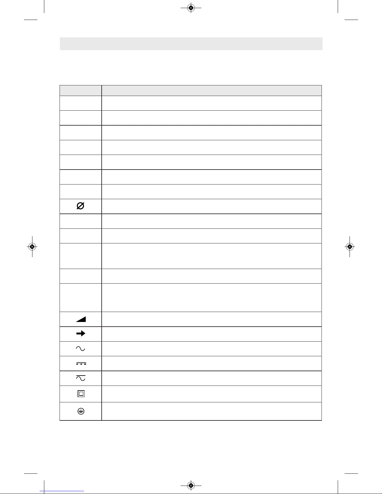
Symbols
IMPORTANT: Some of the following symbols may be used on your tool. Please study them
and learn their meaning. Proper interpretation of these symbols will allow you to operate the
tool better and safer.
Symbol Designation / Explanation
V Volts (voltage)
A Amperes (current)
Hz Hertz (frequency, cycles per second)
W Watt (power)
kg Kilograms (weight)
min Minutes (time)
s Seconds (time)
Diameter (size of drill bits, grinding wheels, etc.)
n
0
No load speed (rotational speed at no load)
n Rated speed (maximum attainable speed)
.../min
Revolutions or reciprocation per minute (revolutions, strokes, surface speed,
orbits etc. per minute)
0 Off position (zero speed, zero torque...)
1, 2, 3, ...
I, II, III,
Selector settings (speed, torque or position settings. Higher number means
greater speed)
0
Infinitely variable selector with off (speed is increasing from 0 setting)
Arrow (action in the direction of arrow)
Alternating current (type or a characteristic of current)
Direct current (type or a characteristic of current)
Alternating or direct current (type or a characteristic of current)
Class II construction (designates double insulated construction tools)
Earthing terminal (grounding terminal)
2610042685 DDH183 HDH183.qxp_DDH - HDH 1/22/16 12:26 PM Page 6
-7-
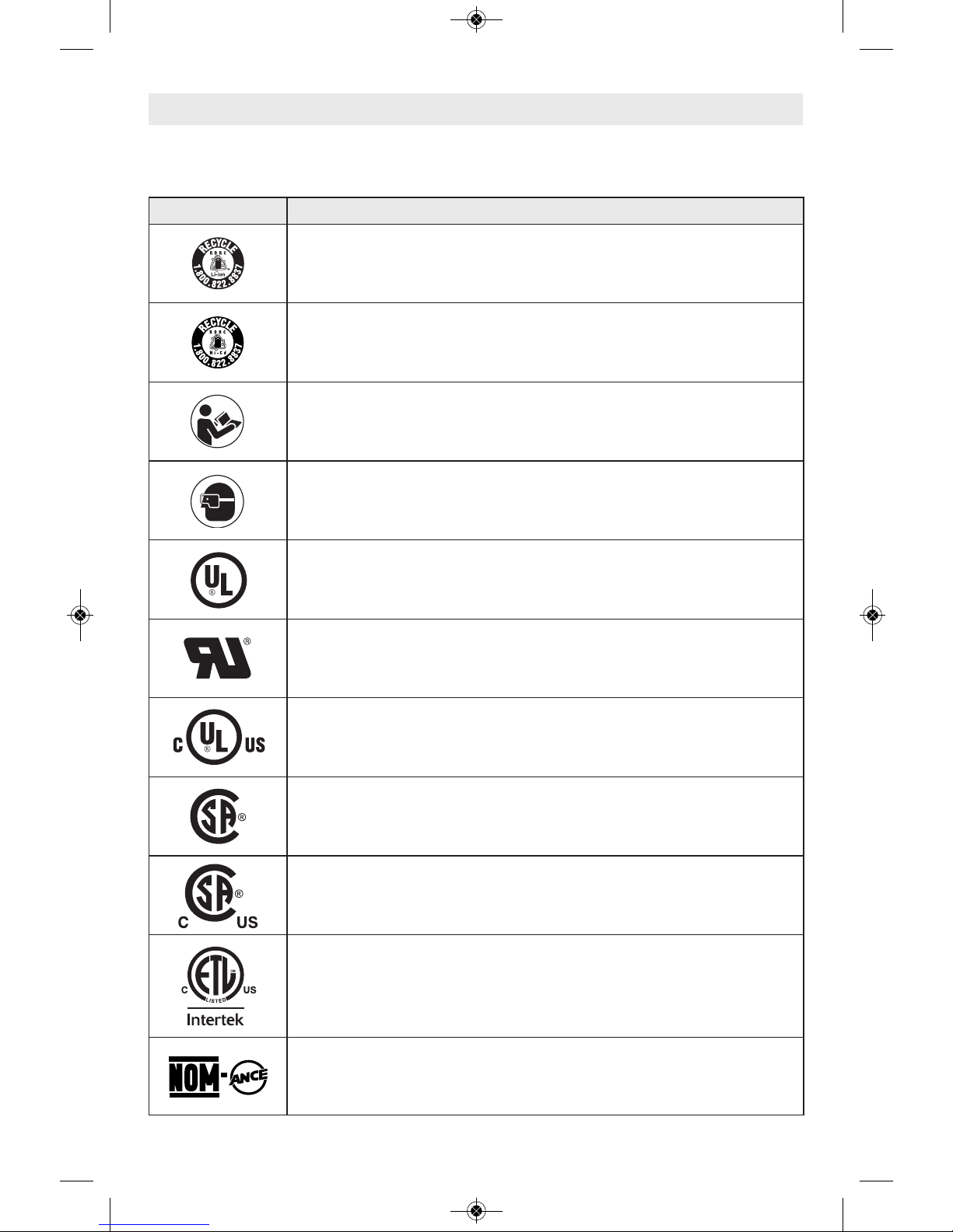
Symbols (continued)
IMPORTANT: Some of the following symbols may be used on your tool. Please study them
and learn their meaning. Proper interpretation of these symbols will allow you to operate the
tool better and safer.
Symbol Designation / Explanation
Designates Li-ion battery recycling program
Designates Ni-Cad battery recycling program
Alerts user to read manual
Alerts user to wear eye protection
This symbol designates that this tool is listed by Underwriters Laboratories.
This symbol designates that this component is recognized by Underwriters
Laboratories.
This symbol designates that this tool is listed by Underwriters Laboratories,
to United States and Canadian Standards.
This symbol designates that this tool is listed by the Canadian Standards
Association.
This symbol designates that this tool is listed by the Canadian Standards
Association, to United States and Canadian Standards.
This symbol designates that this tool is listed by the Intertek Testing
Services, to United States and Canadian Standards.
This symbol designates that this tool complies to NOM Mexican Standards.
2610042685 DDH183 HDH183.qxp_DDH - HDH 1/22/16 12:26 PM Page 7
-8-
Functional Description and Specifications
Disconnect battery pack from tool before making any assembly,
adjustments or changing accessories. Such preventive safety measures
reduce the risk of starting the tool accidentally.
Cordless Drill Drivers and
Cordless Hammer Drills
Battery Packs/Chargers
Please refer to the Charger Manual included with your tool.
NOTE: For tool specifications refer to the nameplate on your tool.
Model number DDH183 HDH183
Voltage rating 18 V 18 V
No load speed 1 n
0
0-480/min n0 0-480/min
No load speed 2 n
0
0-2100/min n0 0-2100/min
Impact rate NA 0-31500 BPM
Maximum Capacities
Chuck size 1/2" 1/2"
Driving screw sizes #14 x 3" #16 x 3"
Drilling mild metal 1/2" 1/2"
Drilling hard wood 1-1/2" 1-3/8"
Drilling soft wood 2" 1-7/8"
Drilling masonry NA 5/8"
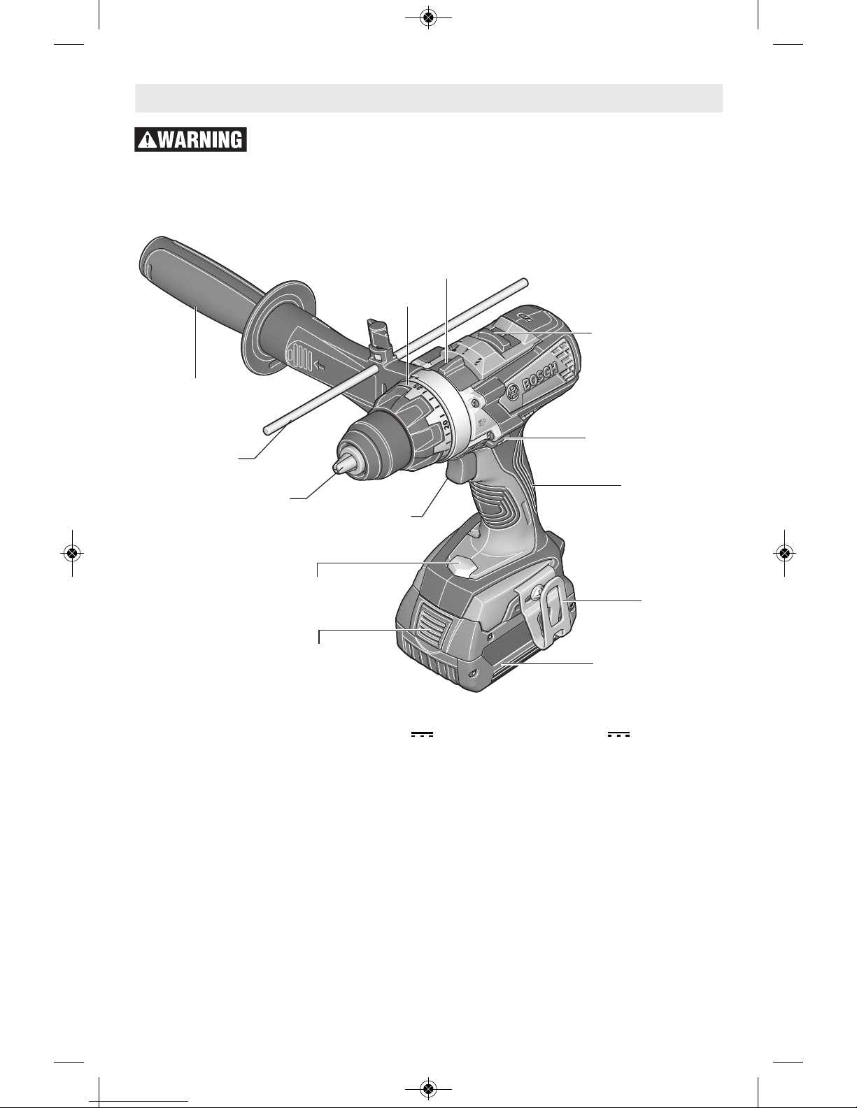
ADJUSTABLE
CLUTCH
MODE SELECTOR
SWITCH
VARIABLE SPEED
TRIGGER SWITCH
BUILT IN
WORK LIGHT
BATTERY PACK
RELEASE BUTTON
B
A
TTER
Y
P
A
C
K
KEYLESS
CHUCK
FORWARD/
REVERSING LEVER
AND TRIGGER LOCK
RUBBERIZED
GRIP
BELT CLIP
DEPTH
GAUGE
AUXILIARY
HANDLE
GEAR SHIFTER /
SPEED RANGE
SELECTOR
2610042685 DDH183 HDH183.qxp_DDH - HDH 1/22/16 12:26 PM Page 8
Disconnect battery pack
from tool before making
any assembly, adjustments or changing
acc essori es. Suc h preven tive saf ety
measures reduce the risk of starting the tool
accidentally.
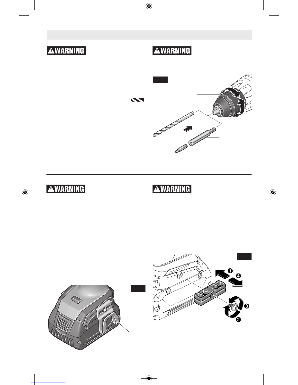
INSERTING BITS
Move reverse switch lever to the center “OFF”
position. Remove battery pack and turn the
mode selector switch to the drilling
position. Rotate the chuck sleeve counterclockwise viewing from chuck end, and open
chuck to approximate drill bit diameter. Insert
a clean bit up to the drill bit flutes for small bits,
or as far as it will go for large bits. Close chuck
by rotating the chuck sleeve clockwise and
securely tighten by hand (Fig. 2). Return the
mode selctor switch to desired position.
Do not use the power of
the drill while grasping
chuck to loosen or tighten bit. Friction burn
or hand injury is possible if attempting to grasp
the spinning chuck.
Assembly
FIG. 2
BELT CLIP
When the tool is attached to
the belt, position yourself to
avoid entanglement with surrounding objects.
Unexpected entanglement could cause the tool
to fall resulting in injury to the operator or
bystanders.
The belt clip accessory wil l allow y ou to
conveniently attach your tool to your belt. This
feature will allow you to have both hands free
when climbing a ladder or moving to another
work area.
The belt clip can be attached to either side of
the tool by securing it with a mounting screw.
Always make sure you securely tighten the
mounting screw before use (Fig. 3).
To use clip, turn tool upside down and attach
to your belt.
4X BIT TIP HOLDER
Store only bit tips in the
on-tool bit holder. Longer
bits could interfere with proper tool operation
and result in user injury.
The four piece bit tip holder can be used for
co nvenient on too l storage of your mos t
commonly used bits.
When mounting bit holder accessory, mount on
the side of the drill opposite the belt clip.
Always make sure you securely tighten the
mounting screw before use. (Fig. 4).
BELT CLIP
FIG. 3
FIG. 4
BIT HOLDER
-9-
CHUCK SLEEVE
DRILL BIT
BIT HOLDER
SCREWDRIVER BIT
CLOSE
OPEN
2610042685 DDH183 HDH183.qxp_DDH - HDH 1/22/16 12:26 PM Page 9
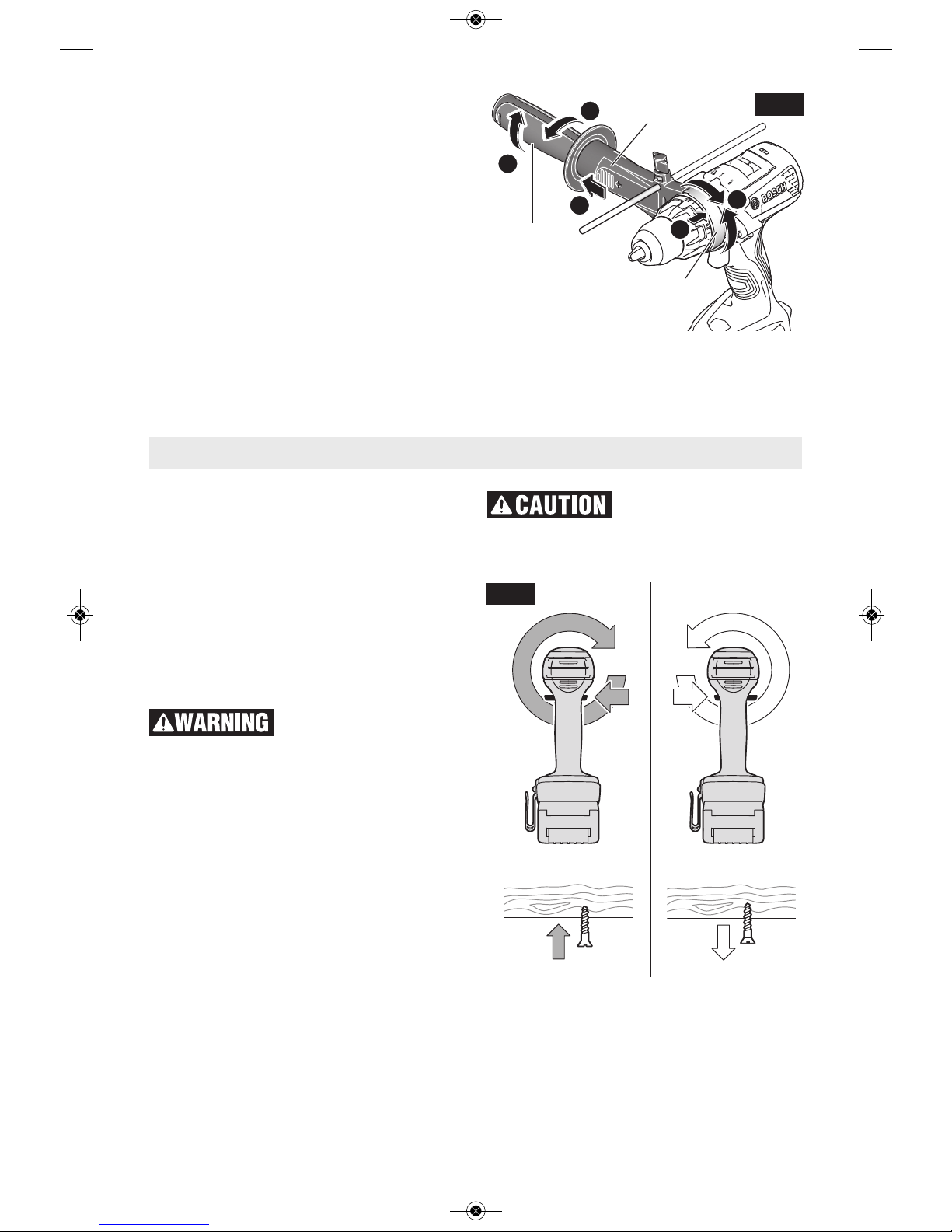
AUXILIARY HANDLE
T
he tool must be supported with the auxiliary
handle during operation.
To mount the auxiliary handle on the tool
loosen the hand grip (A). Pull on the sleeve
(B) and slide the collar on to the tool as
shown (C). Swivel the handle to desired
position (D). Secure the handle in place by
tightening the hand grip (E). See Fig. 5.
To remove the handle for transportation or
storage reverse the steps above.
-10-
A
B
D
C
E
HAND GRIP
SLEEVE
COLLAR
FIG. 5
VARIABLE SPEED CONTROLLED
TRIGGER SWITCH
Your tool is equipped with a variable speed
trigger switch. The tool can be turned "ON" or
"OFF" by squeezing or releasing the trigger.
The speed can be adjusted from the minimum
to maximum nameplate RPM by the pressure
you apply to the trigger. Apply more pressure
to increase the speed and release pressure to
decrease speed (Fig. 1).
FORWARD/REVERSING
LEVER & TRIGGER LOCK
After tool use, lock trigger
in “OFF” position to help
prevent accident al starts and accide ntal
discharge.
You r t o o l is equipped wit h a f o r ward/
reversing lever and trigger lock located above
the trigger (Fig. 6). This lever was designed
for changing rotation of the bit, and for locking
the trigger in an “OFF” position.
For forward rotation, (with chuck pointed away
from you) move the lever to the far left (Fig. 6).
For reverse rotation move the lever to the far
right (Fig. 6). To activate trigger lock move
lever to the center off position.
Do not change direction
of rotation until the tool
comes to a complete stop. Shifting during
rotation of the chuck can cause damage to
the tool.
Operating Instructions
FIG. 6
2610042685 DDH183 HDH183.qxp_DDH - HDH 1/22/16 12:26 PM Page 10
-11-
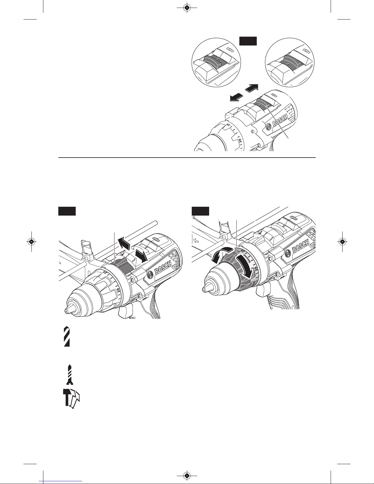
GEAR SHIFTING
Your tool is equipped with two separate gear
ranges, low gear 1 and high gear 2. Low gear
pr ovides h igh-torqu e an d sl ower drilling
speeds for heavy duty work or for driving
screws. High gear provides faster speeds for
drilling lighter work. To change speeds slide
switch, to the high 2 or low position 1 (Fig. 7).
AT TENTION: If your tool appe ars to b e
running, but the chuck will not turn, check to
make sure the gear shifter is pushed fully into
desired setting.
GEAR
SHIFTER
FIG. 7
MODE SELECTOR SWITCH
The mode selector switch allows the tool to
be set f o r various d r i l l i ng or d r i v i n g
applications. Turn the mode selector switch
right or left d epending on the b elow
applications (Fig. 8).
Drill only action: This mode will lock up
the clutch to permit drilling and driving
heavy duty work, and also will enable
bits to be changed quickly and easily in
the keyless chuck
Driver mode: To drive screws, nuts,
and bolts with use of the adjustable
clutch settings.
Drill with hammer action (HDH183
Mod el onl y): For dril ling i n
concrete, asphalt, tile or other similar
hard materials. The hammer drill
position overrides the clutch for
drilling.
ADJUSTABLE CLUTCH
Your tool features 25 clutch settings. Output
torque will increase as the clutch ring, is
rotated from 1 to 25. The tool will stop rotating
as soon as the set torque is reached during
operation (Fig. 9).
BRAKE
When the tr igger sw i t c h is released it
activates the brake to stop the chuck quickly.
This is especially useful in the repetitive
driving and removal of screws.
BUILT IN WORK LIGHT
Your tool is also equipped with a light that turns
on automatically when the switch is activated,
for better visibility when drilling/driving (Fig. 1).
ADJUSTABLE
CLUTCH
FIG. 9FIG. 8
MODE
SELECTOR
SWITCH
2610042685 DDH183 HDH183.qxp_DDH - HDH 1/22/16 12:26 PM Page 11
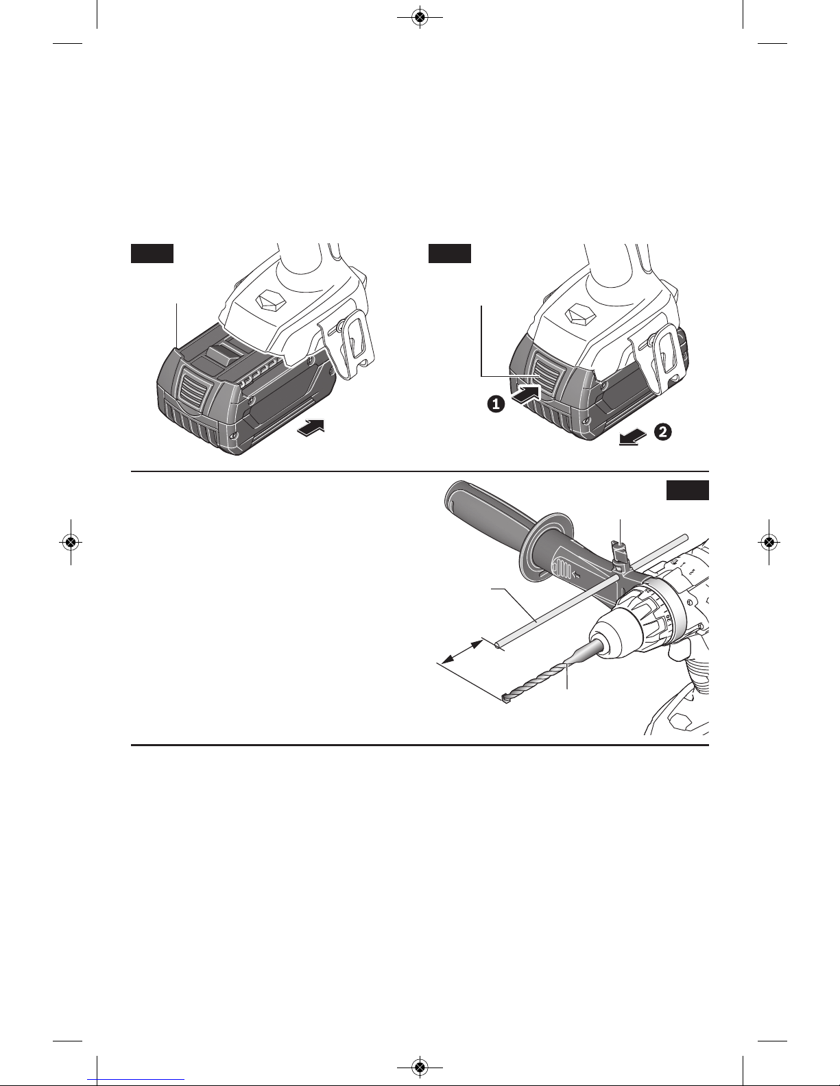
Set Forward/Reversing lever to the center (off
position). Slide charged battery pack into the
housi ng until the battery pack locks into
position (Fig. 10).
Your tool is equipped with a secondary locking
lat ch to prev ent the ba ttery pack from
completely falling out of the handle, should it
become loose due to vibration.
To remove the battery pack, press the battery
pack release button and slide the battery pack
forward (Fig. 11).
Press the battery pack release button again
and slide the battery pack completely out of
tool housing (Fig. 11).
INSERTING AND RELEASING BATTERY PACK
BATTERY PACK
RELEASE BUTTON
FIG. 10 FIG. 11
BATTERY PACK
-12-
DEPTH GAUGE
Your drilling depth can be pre-set and/or
repeated by using the depth gauge.
Setting depth: After the auxiliary handle is
installed, make sure the drill bit has been fully
inserted into the chuck before setting the depth
gauge.
To adjust depth, turn the wing nut counterclockwise to loosen depth gauge, slide depth
gauge to desired depth X and securely tighten
wing nut clockwise (Fig. 12).
TEMPERATURE OVERLOAD PROTECTION
Avo id usin g batter y operat ed tools
continuously, for long periods of time, while
subjecting the tool to overload conditions, such
as drilling with large diameter accessories into
hard materials. Using battery powered tools at
extreme loads, may cause the battery to
exceed its allowable operating temperature
range. When the battery exceeds normal
operating temperature caused by overload, the
speed of the tool may be reduced and the tool
may appear to lose power. To regain the tool's
full performance, the battery must be allowed
to cool, until the operating temperature returns
to normal.
RAPID SHUT-OFF (KICK BACK CONTROL)
To ensure better control of the tool during
operation, this tool is design to shut-off while in
use if a sudd en or unexp ected bind up
situation occurs. Bind up occurs when the bit
gets jammed during operation, which forces
the bit to stop spinning abruptly. If this occurs,
the tool will shut down and the Rapid Shut-off
will be indicated by a flashing LED on the tool.
This feature can only be activated when the
tool is running at maximum speed.
FIG. 12
DEPTH
GAUGE
X
WING
NUT
DRILL BIT
2610042685 DDH183 HDH183.qxp_DDH - HDH 1/22/16 12:26 PM Page 12
DRIVING NUTS AND BOLTS
Variable speed control must be used with
caution for driving nuts and bolts with socket
set attach ments. The technique is to start
slowly, increasing speed as the nut or bolt runs
d
own. Set the nut or bolt snugly by slowing the
drill to a stop. If this procedure is not followed,
the tool will have a tendency to torque or twist
in your hands when the nut or bolt seats.
DRILLING
You will extend the life of your bits and do
neater work if you always put the bit in contact
with the work before pulling the trigger. During
the oper a tion, hold the tool firmly and exert
light, steady pressure. Too much pressure at
low speed will stall the tool. Too little pressure
will keep the bit from cutting and cause excess
friction by sliding over the surface. This can be
damaging to both tool and bit.
DRILLING WITH VARIABLE SPEED
The variable speed trigger allows you to slowly
increase RPM. By using a slow starting speed,
you are able to keep the bit from “wander ing”.
You can increase the speed as the bit “bites”
into the work by squeezing the trigger.
DRIVING WITH VARIABLE SPEED
Variable speed drills will double as a power
screwdriver by using a screwdriver bit. Prior to
driving screws, pilot and clearance holes should
be drilled. Place the threaded end of the screw
in the pilot or clearance hole and start driving
the screw slowly, increasing the speed as the
screw runs down. Set the screw snugly by
slowing to a stop.
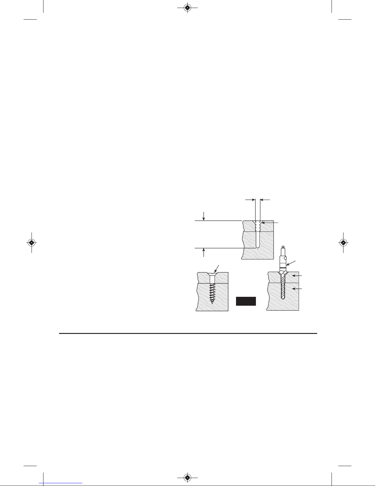
FASTENING WITH SCREWS
The procedure shown in Fig. 13 will enable
you to fasten materials together using your
drill without stripping, splitting or separating
the material.
First, clamp the pieces together and drill the
hole 2/3 the diameter of the screw. If the
material is soft, dril l only 2/3 the proper
length. If it is hard, drill the entire length.
Second, unclamp the pieces and drill the
hole in the top piece of wood again to the
same diameter as the shank of the screw.
Third, if flat head screw is used, countersink
the hole to make the screw flush with the
surface. Realign the holes on the two pieces
and apply even pressure when driving the
screw. The screw shank clearance hole in
the first piece allows the screw head to pull
the pieces tightly together.
The adjustable screw drill accessory will do
all of these operations quickly and easily.
Screw drills are available for screw sizes No.
6, 8, 10 and 12.
Operating Tips
2. Drill same
diameter as
screw shank.
3. Countersink
same diameter
as screw head.
1. Drill 2/3 diameter and
2/3 of screw length for
soft materials, full
length for hard
materials.
Adjustable
Screw
Drill
Screw
Apply a slight
even pressure
when driving
screws.
FASTENING
WITH SCREWS
FIG. 13
-13-
DRILL BITS
Always inspect drill bits for excessive wear.
Use only bits that are sharp and in good
condition.
TWIST BITS: Available with straight and
reduced shanks for wood and light duty metal
drilling. High speed bits cut faster and last
longer on hard ma terials.
CARBIDE TIPPED BITS: Used for drilling
stone, con crete, plaster, cement and other
unusually hard nonmetals. Use continuous
heavy feed pres sure when employing carbide
tip bits.
DRILLING WOOD
Be certain workpiece is clamped or anchored
firm ly. Always apply pressure in a straight line
with the drill bit. Maintain enough pressure to
keep the drill “biting”.
When drilling holes in wood, twist bits can be
used. Twist bits may overheat unless pulled out
frequently to clear chips from flutes.
Use a “back-up” block of wood for work that is
likely to splinter, such as thin materials.
You will drill a cleaner hole if you ease up on
the pressure just before the bit breaks through
Top
Bottom
2610042685 DDH183 HDH183.qxp_DDH - HDH 1/22/16 12:26 PM Page 13
Before using an
accessory, be certain that
its maximum safe operating speed is not
exceeded by the nameplate speed of the
tool. Do not exceed the recommended wheel
diameter.
SANDING AND POLISHING
Fine sanding and polishing re quire “touch”.
Select the most efficient speed.
When using polishing bonnets, alway be sure
the excess string that secures the bonnet is
tucked well within the bonnet during operation.
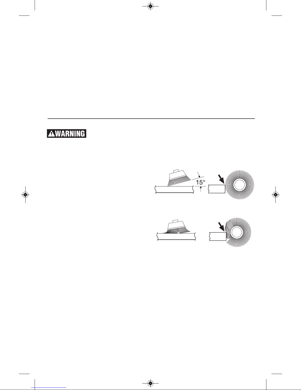
WIRE BRUSHES
Work with brushes requires high speeds.
BRUSHING PRESSURE
1. Let the tips of a wire brush do the work.
Operate the brush with the lightest pressure
so only the tips of the wire come in contact
with the work.
2. If heavier pressures are used, the wires
will be overstressed, resulting in a wiping
action; and if this is continued, the life of the
brush will be shortened due to wire fatigue.
3. Apply the brush to the work in such a way
that as much of the brush face as possible is
in full contact with the work. Applying the
side or edge of the brush to the work will
result in wire breakage and shortened brush
life.
-14-
the wood. Then complete the hole from the
back side.
DRILLING METAL
There are two rules for drilling hard materials.
First, the harder the material, the greater the
pres sure you need to apply to the tool. Second,
the harder the material, the slower the speed.
Here are a couple of tips for drilling in metal.
Lubri cate the tip of the bit occasionally with
cutting oil except when drilling soft metals such
as alu minum, cop per or cast iron. If the hole to
be drilled is fairly large, drill a smaller hole first,
then enlarge to the required size, it’s often
fa ster in the long run. Mai n tain enough
pressure to assure that the bit does not just
spin in the hole. This will dull the bit and greatly
shorten its life.
DRILLING MASONRY
Soft materials such as brick are relatively easy
to drill. Concrete however, will require much
more pressure to keep the bit from spinning. Be
sure to use carbide tip bits for all masonry
work.
CORRECT: Wire tips doing the work.
INCORRECT: Excessive pressure can cause wire breakage.
2610042685 DDH183 HDH183.qxp_DDH - HDH 1/22/16 12:26 PM Page 14
 Loading...