

Bosch Hanbury 4, Hanbury 5, Hanbury 8 Installation, Servicing And User Instructions Manual
Installation, servicing and user instructions
Multifuel Stove-Defra Exempt Smokeless Fuel
Greenstyle Hanbury
4, 5 & 8
HANBURY4COVER.qxp_Ri 1224 manual V5 Current 13/04/2016 16:59 Page 1

CONTENTS
1. KEY TO SYMBOLS AND SAFETY INSTRUCTIONS .................................................................................... 3
2. APPLIANCE INFORMATION ........................................................................................................................ 4
3. USER INFORMATION .................................................................................................................................. 4-5
4. INSTALLATION .............................................................................................................................................6-20
5. COMMISSIONING ......................................................................................................................................... 21
6. USER INSTRUCTION ................................................................................................................................... 21-25
7. SERVICE AND SPARES ............................................................................................................................... 26-31
8. NOTES ........................................................................................................................................................... 32-33
9. COMMISSIONING CHECKLIST ................................................................................................................... 34
10. SERVICE RECORD ...................................................................................................................................... 35
2 6720819898 C 11/2017
KEY TO SYMBOLS AND SAFETY INSTRUCTIONS
1 2 3 4 5 6 7 8
1 2 3 4 5 6 7 8
9 10 11 12 13 14 15 16
1 2 3 4 5 6 7 8
9 10 11 12 13 14 15 16
1 KEY TO SYMBOLS AND SAFETY INSTRUCTIONS
1.1 KEY TO SYMBOLS
Warnings
WARNINGS IN THIS DOCUMENT ARE
IDENTIFIED BY A WARNING TRIANGLE
PRINTED AGAINST A GREY BACKGROUND.
KEYWORDS AT THE START OF A WARNING
INDICATE THE TYPE AND SERIOUSNESS
OF THE ENSUING RISK IF MEASURES TO
PREVENT THE RISK ARE NOT TAKEN.
The following keywords are dened and can be used in this
document:
NOTICE indicates a situation that could result in damage to
property or equipment.
CAUTION indicates a situation that could result in minor to medium
injury.
WARNING indicates a situation that could result in severe injury
or death.
DANGER indicates a situation that will result in severe injury or
death.
IMPORTANT INFORMATION
This symbol indicates important information where there
is no risk to people or property.
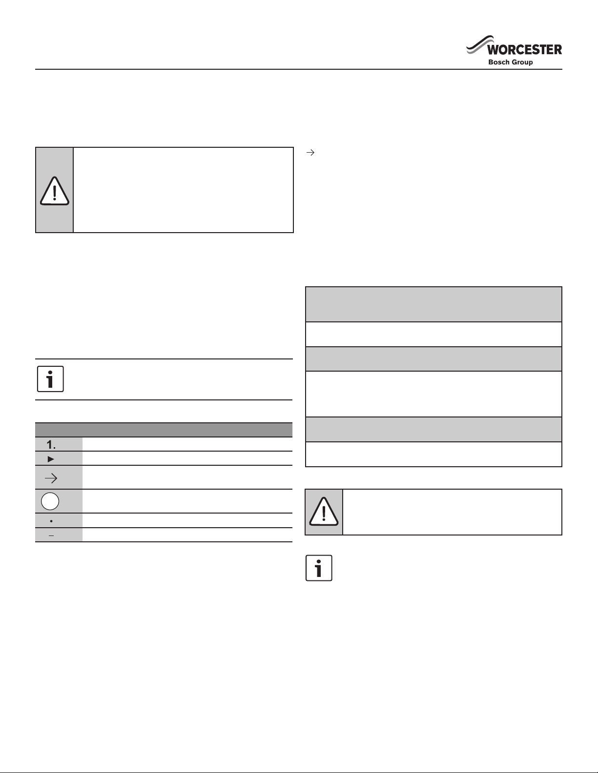
ADDITIONAL SYMBOLS
Symbol Meaning
a numbered step in an action sequence
a step in an action sequence
a reference to a related part in the document or to
other related documents
a reference number to identify or refer to a part or
item
a list entry
a list entry (second level)
A REFERENCE TO A RELATED PART IN THE DOCUMENT
OR TO OTHER RELATED DOCUMENTS.
To refer the reader to a specic gure/table/section within the
manual.
e.g. gure 1.
A reference number to identify or refer to a part or item.
In a related gure, items or parts identied by a sequential number.
List entries, rst and second levels
• A single component/item
• A component/list, made up of multiple parts/items.
– Sub component or sublist of main component/list.
– etc.
PLEASE READ THESE INSTRUCTIONS CAREFULLY
BEFORE STARTING INSTALLATION.
These instructions are applicable to the Worcester appliance
model(s) stated on the front cover of this manual only and must
not be used with any other make or model of appliance.
These instructions apply in the UK and Ireland only and must
be followed except for any statutory obligations.
If you are in any doubt, contact the Worcester Technical helpline
(0330 123 2445).
Please leave these instructions with the completed
CHECKLIST, (or a certicate conrming compliance with
IS 813, Eire only) and the user manual with the owner after
installation or servicing.
Distance learning and training courses are available from
Worcester.
The CHECKLIST can be found in the back of this Installation
manual.
This is a multifuel burning stove, and as such has
only been tested and certied to burn wood and Defra
exempt smokeless fuel. Failure to adhere to this can
invalidate the manufacture’s guarantee.
EXAMPLES OF ADDITIONAL SYMBOLS USED
A numbered step in an action sequence
A sequence of numbered steps or actions carried out in a specic
order to complete a task.
1. First action
2. Second action
3. Third action
etc.
A STEP IN AN ACTION SEQUENCE
A sequence of dened actions or steps carried out in order to
complete
► a task.
► Action
► Next action
► etc.
Read the instruction booklet and these supplementary
instructions carefully before installation.
36720819898 C 11/2017
APPLIANCE INFORMATION
APPLIANCE
The Checklist can be used to demonstrate compliance with
Building Regulations and should be provided to the customer for
future reference.
HEALTH AND SAFETY
The appliance contains no asbestos and no substances have
been used in the construction process that contravene the
COSHH Regulations (Control of Substances Hazardous to Health
Regulations 1988).
COMBUSTION AND CORROSIVE MATERIALS
Do not store or use any combustible materials (paper, thinners,
paints etc.) inside or within the vicinity of the appliance. Chemically
aggressive substances can corrode the appliance and invalidate
any warranty.
FITTINGS AND MODIFICATIONS
Fitting the appliance and any controls to the appliance may only
be carried out by a qualied, competent engineer. Flue systems
must not be modied in any way other than as described in the
tting instructions. Any misuse or unauthorized modications to
the appliance, ue or associated components and systems could
invalidate the warranty. The manufacturer accepts no liability
arising from any such actions, excluding statutory rights.
SERVICING
Advise the user to have the system serviced annually by a
competent, qualied registered engineer. Approved spares must
be used to help maintain the economy, safety and reliability of the
appliance.
IMPORTANT
The service engineer must complete the Service Record on the
Checklist after each service.
WORCESTER ORIGINAL SPARE PARTS
Only use Worcester original spare parts with this appliance. Non
Worcester original spare parts will invalidate the guarantee (if
applicable) and any warranty.
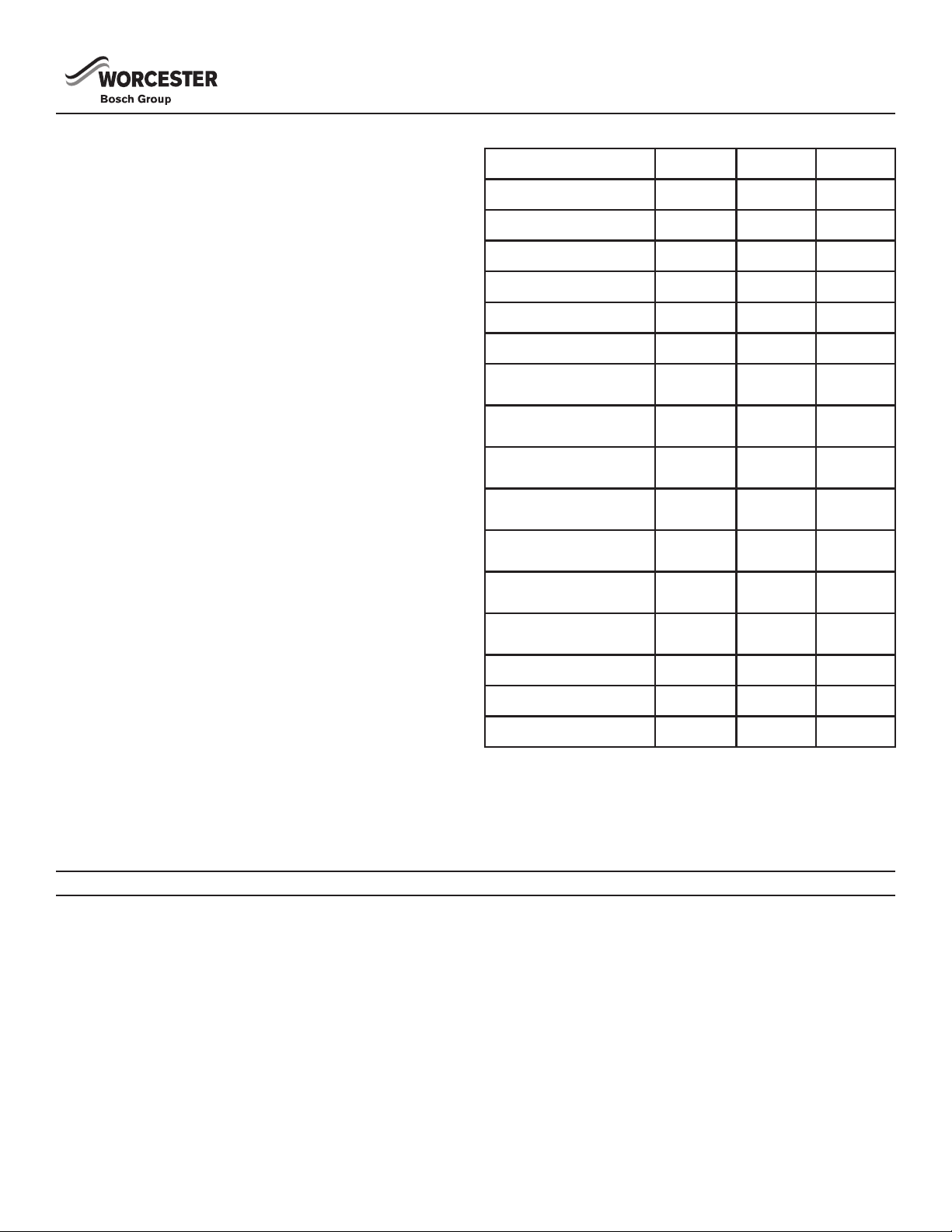
TECHNICAL DATA
TECHNICAL DATA Hanbury 4 Hanbury 5 Hanbury 8
Height To Top Of Stove 546mm 583mm 621mm
Height To Top Of Spigot 585mm 622mm 664mm
Width 394mm 419mm 436mm
Depth 325mm 341mm 440mm
Weight 63kg 77kg 99kg
Flue Pipe 127mm 127mm 127mm
Nominal Thermal Output
(Wood)
Nominal Thermal Output
(Smokeless)
Fluegas Mass
Flow(closed) (Wood)
Fluegas Mass Flow
(closed) (Smokeless)
Fluegas Temperature
(closed) (Wood)
Fluegas Temperature
(closed) (Smokeless)
Minimum ue pressure
(closed)
Efciency (Wood) 86% 78% 78%
Efciency (Smokeless) 71% 68% 67%
Maximum Output 6.1kW 7.5kW 11.6kW
4.2kW 5.0kW 7.7kW
4.3kW 5.0kW 7.5kW
2.8g/s 4.8g/s 4.8g/s
5.0g/s 6.7g/s 9.7g/s
179 °C 253 °C 313 °C
312 °C 306 °C 345 °C
12Pa 12Pa 12Pa
IMPORTANT INFORMATION
The installation and operation information given here is of a general
nature. National and European standards, and building regulations
as well as re prevention laws must be observed during the
operation of the stove.
USER INFORMATION
GENERAL SAFETY INSTRUCTIONS FOR THE OPERATION OF YOUR STOVE
• Thoroughly read the entire manual before starting up your stove
and observe the caution notices.
• Your heating unit may not be moved without approved means of
transport with sufcient load-bearing capacity
• Your heating unit is not suitable to be used as a stand or as a
ladder
• Only burn approved fuels and materials listed in the chapter
Clean Burning
• Do not wear loose or ammable clothing when adding fuel to the
re in your stove.
• Placing non-heat-related objects on the stove or in the vicinity of
the stove is forbidden.
• Make your children aware of this particular danger and keep them
at a safe distance from the stove whenever it is in operation.
• The burning or placing of ammable or explosive materials, such
as empty spray cans and such like items into the rebox as well
as the storage of such materials in the immediate vicinity of your
stove is strictly prohibited due to the danger of explosion.
• Do not lay laundry on the stove for drying. Laundry hung up to
dry must be kept at a safe distance from the stove because of
the danger of re.
• During the operation of your stove, it is forbidden to use ammable
or explosive materials in the same or an adjacent room to the
one in which your stove is located.
4 6720819898 C 11/2017
USER INFORMATION
ADDITIONAL INFORMATION BEFORE INSTALLING
YOUR MULTIFUEL STOVE
• Once you determine the room in which your multifuel stove will be
installed, install a carbon monoxide alarm in the same room. This
alarm should be installed 1-3m from the stove. When mounted
on a wall it must be at least 150mm below the ceiling. When
mounted to the ceiling it must be 300mm away from all walls.
• All local regulations, including those referring to national and
European standards need to be complied with when installing
the appliance.
• Any air inlet grilles are to be positioned so they are not liable to
blockage.
• Do not use your appliance as an incinerator. Only burn well
seasoned wood or Defra exempt smokeless fuel.
• A minimum of annual maintenance is necessary to be sure
your appliance is running optimally. All maintenance must be
performed by a competent engineer or Chimney Sweep. Access
should be provided for regular cleaning of the appliance, ue gas
connector and chimney ue.
• Do not operate your appliance with the fueling door open. Only
operate with the fueling door open during ignition, refueling and
removal of residue material to prevent fume spillage. Operating
with the fueling door open can cause over-ring of your appliance.
Operation with the door open can cause excess smoke.
WARNING: Some parts of your appliance, especially
the external surfaces, will be hot to touch when in
operation. Due care should be taken to prevent
burns. Keep children away from the appliance during
operation.
• This appliance is NOT suitable for installation in a shared ue
system.
• This appliance is suitable and has been tested for intermittent
operation.
• There must be no unauthorized modication of the appliance.
THE CLEAN AIR ACT 1993 AND SMOKE CONTROL
AREAS
Under the Clean Air Act local authorities may declare the whole
or part of the district of the authority to be a smoke control area. It
is an offence to emit smoke from a chimney of a building, from a
furnace or from any xed boiler if located in a designated smoke
control area. It is also an offence to acquire an “unauthorized fuel”
for use within a smoke control area unless it is used in an “exempt”
appliance (“exempted” from the controls which generally apply in
the smoke control area).
In England, appliances are exempted by publication on a list by the
Secretary of State in accordance with changes made to sections 20
and 21 of the Clean Air Act 1993 by section 15 of the Deregulation
Act 2015. Similarly in Scotland, appliances are exempted by
publication on a list by Scottish Ministers under section 50 of the
Regulatory Reform (Scotland) Act 2014.
In Wales and Northern Ireland, these are authorised by regulations
made by Welsh Ministers and by the Department of the Environment
respectively.
The Hanbury 4 has been recommended as suitable for use in smoke
control areas when burning wood logs or Defra exempt smokeless
fuel, when operated in accordance with these instructions and when
tted with a modication that prevents closure of the Secondary Air
control.
The Hanbury 5 has been recommended as suitable for use in smoke
control areas when burning wood logs or Defra exempt smokeless
fuel, when operated in accordance with these instructions and when
tted with a modication that prevents closure of the Secondary Air
control.
The Hanbury 8 has been recommended as suitable for use in smoke
control areas when burning wood logs or Defra exempt smokeless
fuel, when operated in accordance with these instructions and when
tted with a modication that prevents closure of the Secondary Air
control.
Further information on the requirements of the Clean Air Act can be
found here : https://www.gov.uk/smoke-control-area-rules
Your local authority is responsible for implementing the Clean Air Act
1993 including designation and supervision of smoke control areas
and you can contact them for details of Clean Air Act requirements.
PERMANENT AIR VENT
All stoves requires an adequate air supply in order to operate safely
and efciently. In accordance with current Building Regulations the
installer may have tted a permanent air supply vent into the room
in which the stove is installed to provide combustion air. This air
vent should not under any circumstances be shut off or sealed.
SETTING UP YOUR STOVE
Make sure that the room in which the stove is set up has at least
one door or window into the outside or is directly adjacent to such a
room. Other replaces or exhaust fans must not be operated in the
same room as this stove.
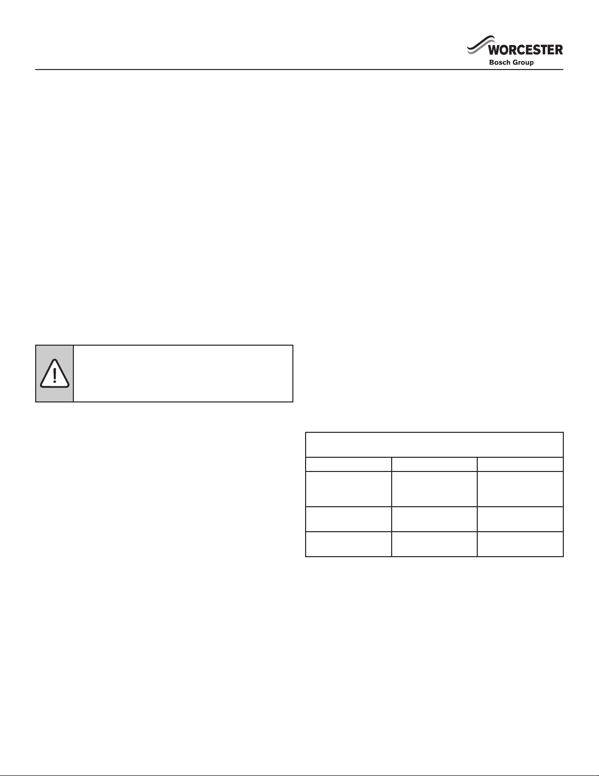
Required safety distances (minimum clearances to combustible
materials.
Hanbury 4 Hanbury 5 Hanbury 8
A > 1200mm
(toward the front of
the stove)
B > 600mm (to the
side)
C > 750mm (to the
back)
A > 1200mm
(toward the front of
the stove)
B > 600mm (to the
side)
C > 725mm (to the
back)
A > 1200mm
(toward the front of
the stove)
B > 700mm (to the
side)
C > 700mm (to the
back)
STOVES GUARANTEE - REGISTRATION
Please visit the website: worcester-bosch.co.uk/guarantee so that
you can register your stove online or via the Worcester Guarantee
App. Alternatively, if you wish to register your Worcester Greenstyle
Stove Guarantee via telephone please call 03301 232 552.
56720819898 C 11/2017
INSTALLATION
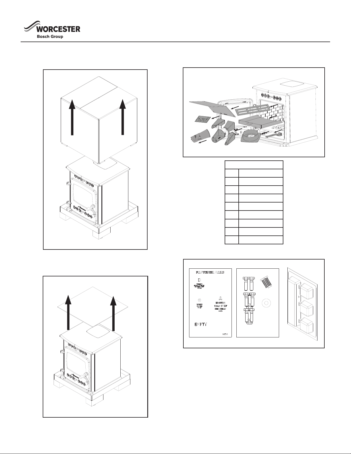
UNPACKING THE APPLIANCE
1. Remove the top section of the box.
3. Remove the bafe, fastener card, legs, ash pan, log guard,
glove, and ue collar from inside the rebox of the stove.
Contents List
Qty. Item
1 Bafe
1 Fastener Card
4 Legs
1 Ash Pan
1 Log Guard
1 Glove
1 Flue Collar
1 Ash PanTool
2. Remove the remaining top panel.
FASTENER CARD
6 6720819898 C 11/2017
INSTALLATION
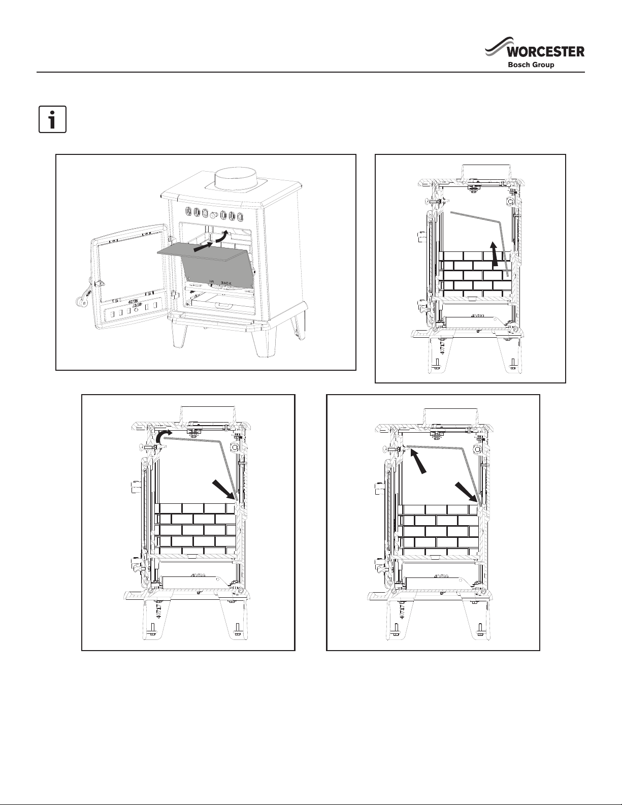
INSTALLING BAFFLE
To locate the bottom of the bafe there is a H4, H5, or H8 (depending on the model purchased) cut into the bottom of the bafe
along with two arrows. When reinstalling the bafe be careful not to install the bafe upside down. When correctly installed the
H4, H5, or H8 cutout will rest on the rear liner as shown and the arrows will be pointing down.
REMOVING THE BAFFLE
► Lift the front edge of the bafe away from the support bars.
► Lift the bafe up off of the rear support bar.
► Lower the bafe and use the front door to remove it from the
unit.
► To replace the bafe simply reverse the order of the above
steps.
Note: Clean the bafe regularly to ensure safe and efcient
operation of the stove.
76720819898 C 11/2017
INSTALLATION
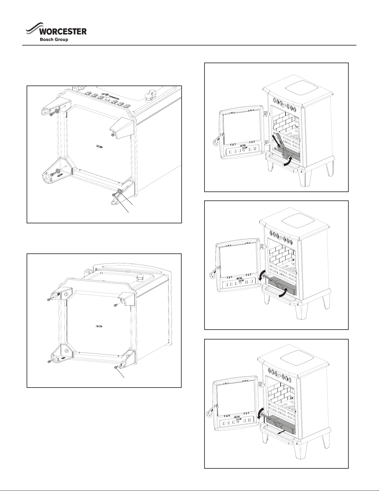
A
C
A
A
INSTALLING THE LEGS
1. Align the leg with the stove.
2. Insert the provided (A) bolt and (C) washer.
3. Repeat for the remaining three legs.
LEG LEVELERS
Insert four (A) bolts into the bottom of the stove leg, and adjust as
needed for leveling.
REMOVING THE ASHPAN
8 6720819898 C 11/2017
INSTALLATION
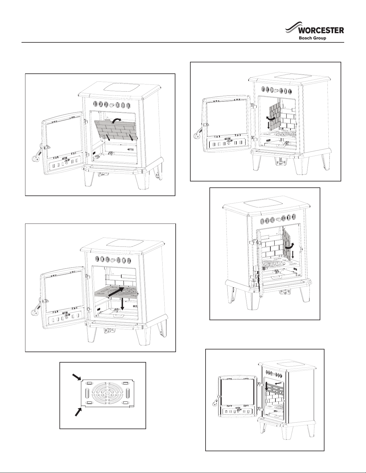
Small Rear Notch
Large Front Notch
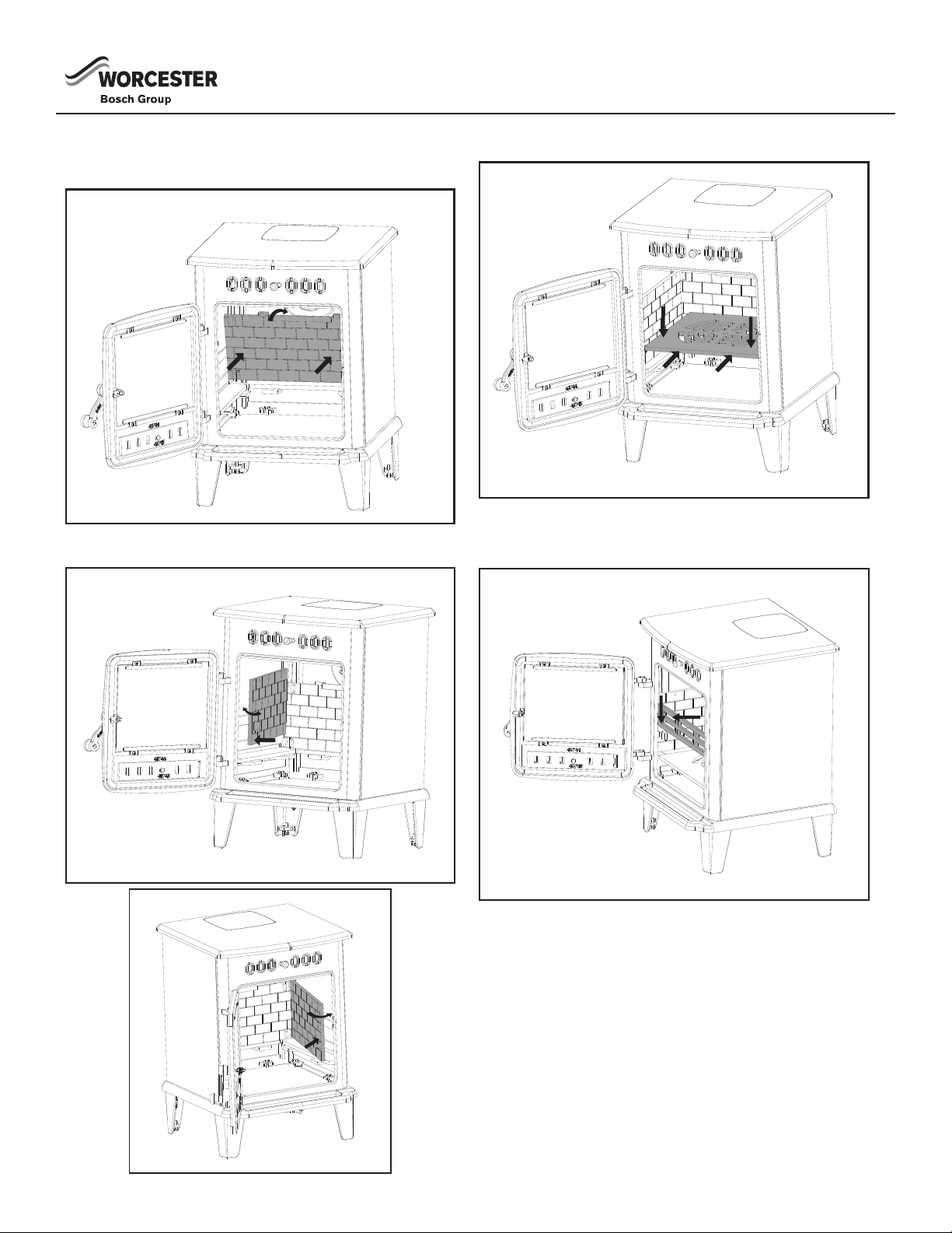
INSTALLING THE BRICK LINERS
HANBURY 4
1. Install the rear liner rst.
2. Next install the grate. Note that there are two small notches
and two large notches. The two large notches must face to
the front of the stove or the grate will not correctly install.
3. Install the left and right brick liners (ip left brick liner to t).
4. Install the log retainer by sliding down into the slots located at
the front of the door.
96720819898 C 11/2017
INSTALLATION
INSTALLING THE BRICK LINERS
HANBURY 5, 8
1. Insert the rear brick liner into the unit through the front door.
2. Next insert the right and left brick liners by sliding them down
into the slots provided.
3. Insert the grate.
4. Slide the log retainer down into the slots located at the front
of the door
10 6720819898 C 11/2017
INSTALLATION
B
C
B
C
B
C
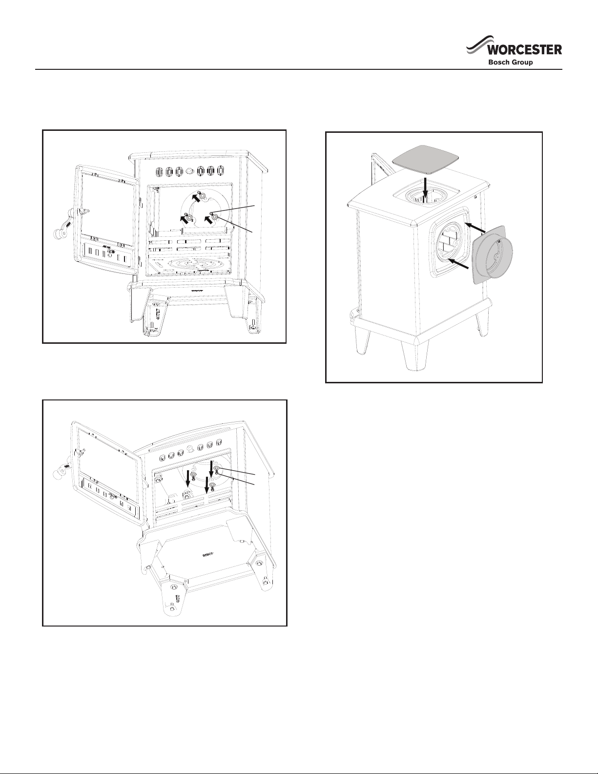
CONVERTING TO USE REAR FLUE
1. Reach in through the front door of the stove and remove the
three (B) bolts, and (C) washers from the ue cover plate.
2. Reach in through the front door of the stove and remove the
three (B) bolts, and (C) washers, that are holding on the ue
collar.
3. Attach the ue collar to the rear of the unit with three (B) bolts
and (C) washers.
4. Attach the ue cover plate to the top of the stove with the three
bolts and washers you previously removed.
116720819898 C 11/2017
 Loading...