

Bosch GWS18V-45, GWS18V-50 Owner’s Manual
IMPORTANT: IMPORTANT : IMPORTANTE:
Read Before Using Lire avant usage Leer antes de usar
Operating/Safety Instructions
Consignes de fonctionnement/sécurité
Instrucciones de funcionamiento y seguridad
For English Version Version française Versión en español
See page 2 Voir page 17 Ver la página 32
1-877-BOSCH99 (1-877-267-2499) www.boschtools.com
Call Toll Free for
Consumer Information
& Service Locations
Pour obtenir des informations
et les adresses de nos centres
de service après-vente,
appelez ce numéro gratuit
Llame gratis para
obtener información
para el consumidor y
ubicaciones de servicio
GWS18V-45
GWS18V-50
2610041372 09-15 GWS18V-45.qxp_GWS 9/18/15 10:00 AM Page 1

-2-
Work area safety
Keep work area clean and well lit. Cluttered
or dark areas invite accidents.
Do not operate power tools in explosive
atmospheres, such as in the presence of
flammable liquids, gases or dust. Power
tools create sparks which may ignite the dust
or fumes.
Keep children and bystanders away while
operating a power tool. Distractions can
cause you to lose control.
Electrical safety
Power tool plugs must match the outlet.
Never modify the plug in any way. Do not
us e a ny adapt e r plugs wi t h e arthed
(grounded) power tools. Unmodified plugs
and matching outlets will reduce risk of electric
shock.
Avoid body contact with earthed or grounded
surfaces such as pipes, radiators, ranges
and refrigerators. There is an increased risk
of electric shock if your body is earthed or
grounded.
Do not expose power tools to rain or wet
conditions. Water entering a power tool will
increase the risk of electric shock.
Do not abuse the cord. Never use the cord
for carrying, pulling or unplugging the power
tool. Keep cord away from heat, oil, sharp
edges or moving parts. Damaged or entangled
cords increase the risk of electric shock.
When operating a power tool outdoors,
use an extension cord suitable for outdoor
use. Use of a cord suitable for outdoor use
reduces the risk of electric shock.
If operating a power tool in a damp location
is unavoidable, use a Ground Fault Circuit
Interrupter (GFCI) protected supply. Use of
an GFCI reduces the risk of electric shock.
Personal safety
Stay alert, watch what you are doing and
us e c o mmon sen se w hen ope r atin g a
power tool. Do not use a power tool while
you are tired or under the influence of drugs,
alcohol or medication. A moment of inattention
while operating power tools may result in
serious personal injury.
Use personal protective equipment. Always
wear eye protection. Protective equipment
such as dust mask, non-skid safety shoes, hard
hat, or hearing protection used for appropriate
conditions will reduce personal injuries.
Prevent unintentional starting. Ensure the
sw itch is in the off- posi tion be fore
connecting to power source and / or battery
pa ck, pic king up or carryi ng the too l.
Carrying power tools with your finger on the
switch or energizing power tools that have the
switch on invites accidents.
Remove any adjusting key or wrench before
turning the power tool on. A wrench or a
key left attached to a rotating part of the power
tool may result in personal injury.
Do not overreach. Keep proper footing and
balance at all times. This enables better
co n trol of the powe r too l in unex p ected
situations.
Dress properly. Do not wear loose clothing
or jewelry. Keep your hair, clothing and
gloves away from moving parts. Loose
clothes, jewelry or long hair can be caught in
moving parts.
If devices are provided for the connection
of dust extraction and collection facilities,
ensure these are connected and properly
used. Use of dust collection can reduce dust-
related hazards.
Power tool use and care
Do not for ce th e pow er to o l. Us e the
correct power tool for your application. The
correct power tool will do the job better and
safer at the rate for which it was designed.
Do not use the power tool if the switch does
not turn it on and off. Any power tool that
ca n n o t be control l e d with the switc h is
dangerous and must be repaired.
Read all safety warnings and all instructions. Failure to follow the warnings
and instructions may result in electric shock, fire and/or serious injury.
SAVE ALL WARNINGS AND INSTRUCTIONS FOR FUTURE REFERENCE
The term “power tool” in the warnings refers to your mains-operated (corded) power tool or
battery-operated (cordless) power tool.
!
WARNING
General Power Tool Safety Warnings
2610041372 09-15 GWS18V-45.qxp_GWS 9/18/15 10:00 AM Page 2

-3-
Power Tool-Specific Safety Warnings
Safety Warnings Common for
Grinding, Sanding, Wire Brushing,
and Abrasive Cutting-Off
Operations:
This power tool is intended to function as a
grinder, sander, wire brush or cut-off tool.
Read all safety warnings, instructions,
illustrations and specifications provided
with this power tool. Failure to follow all
instructions listed below may result in electric
shock, fire and/or serious injury.
Op e ratio n s su c h as poli s hing is no t
recommended to be performed with this
power tool. Operations for which the power
tool was not designed may create a hazard
and cause personal injury.
Do not us e accessori es which are not
specifically designed and recommended by
the tool manufacturer. Just because the
accessory can be attached to your power tool,
it does not assure safe operation.
The rated speed of the accessory must be
at leas t eq u al to the maxi m um sp eed
marked o n the power tool. Accessories
running faster than their RATED SPEED can
break and fly apart.
The outside diameter and the thickness of
your accessory must be within the capacity
rating of your power tool. Incorrectly sized
accessories cannot be adequately guarded or
controlled.
Threaded mounting of accessories must
match the GRINDER spindle thread. For
accessories mounted by FLANGES, the
arbour hole of the accessory must fit the
lo c ating di a meter of th e FLANGE.
Accessories that do not match the mounting
hardware of the power tool will run out of
balance, vibrate excessively and may cause
loss of control.
Do not use a damaged accessory. Before
each use inspect the accessory such as
Disconnect the plug from the power source
a
nd/or the battery pack from the power tool
before making any adjustments, changing
accessories, or storing power tools. Such
preventive safety measures reduce the risk of
starting the power tool accidentally.
Store idle power tools out of the reach of
children and do not allow persons unfamiliar
with the power tool or these instructions to
operate the power tool. Power tools are
dangerous in the hands of untrained users.
Maintain power tools. Check for misalignment
or binding of moving parts, breakage of
parts and any other condition that may
affect the power tool’s operation. If damaged,
have the power tool repaired before use.
Ma n y a c c i dents are caused by poo r l y
maintained power tools.
Keep cutting tools sharp and clean. Properly
maintained cutting tools with sharp cutting
edges are less likely to bind and are easier to
control.
Use the power tool, accessories and tool
bits etc. in accordance with these instructions,
taking into account the working conditions
and the work to be performed. Use of the
power tool for operations different from those
intended could result in a hazardous situation.
Battery tool use and care
Recharge only with the charger specified
by th e ma nufactu rer. A cha rger that i s
suitable for one type of battery pack may
create a risk of fire when used with another
battery pack.
Use power too ls only with specific ally
designated battery packs. Use of any other
battery packs may create a risk of injury and
fire.
When battery pack is not in use, keep it
away from other metal objects like paper
clips, coins, keys, nails, screws, or other
small m e t a l objects that c a n make a
connection from one terminal to another.
Shorting the battery terminals together may
cause burns or a fire.
Under abusive conditions, liquid may be
ejected from the battery, avoid contact. If
contact accidentally occurs, flush with
water. If liquid contacts eyes, additionally
seek medical help. Liquid ejected from the
battery may cause irritation or burns.
Service
Have your power tool serviced by a qualified
re p a i r pe r son us ing o n l y id e n tical
replacement parts. This will ensure that the
safety of the power tool is maintained.
2610041372 09-15 GWS18V-45.qxp_GWS 9/18/15 10:00 AM Page 3

abra sive wheels f or chips and cracks,
b
acking pad for cracks, tear or excess wear,
wire brush for loose or cracked wires. If
power tool or accessory is dropped, inspect
fo r damag e or ins tall an und amag ed
accessory. After inspecting and installing
an a c cess ory, positi on your s elf and
bystanders away from the plane of the
rotating accessory and run the power tool
at maximum no-load speed for one minute.
Damaged accessories will normally break apart
during this test time.
We ar per sona l prote ctiv e equip ment .
Depending on application, use face shield,
sa fety goggl es or safety glass es. As
ap prop riat e, w ear dus t m ask, he aring
protectors, gloves and workshop apron
capable of stopping sma ll ab ras ive or
workpiece fragments. The eye protection
must be capable of stopping flying debris
generated by various operations. The dust
mask or respirator must be capable of filtrating
pa rtic les gen erate d b y yo ur opera tion .
Prolonged exposure to high intensity noise may
cause hearing loss.
Keep bystanders a safe distance away from
work area. Anyone entering the work area
must wear personal protective equipment.
Fr agme nts of wor kpie ce or of a bro ken
accessory may fly away and cause injury
beyond immediate area of operation.
Hold the power tool by insulated gripping
su rfac es onl y, whe n perf ormi ng an
operation where the cutting accessory may
contact hidden wiring. Cutting accessory
contacting a “live” wire may make exposed
metal parts of the power tool “live” and could
give the operator an electric shock.
Never lay the power tool down until the
accessory has come to a complete stop.
The spinning accessory may grab the surface
and pull the power tool out of your control.
Do not run the power tool while carrying it
at your side. Accidental contact with the
spinning accessory could snag your clothing,
pulling the accessory into your body.
Regularly clean the power tool’s air vents.
The motor’s fan will draw the dust inside the
ho usin g and exce ssiv e acc umul atio n of
powdered metal may cause electrical hazards.
Do n ot o pera te the pow er tool ne ar
flammable materials. Sparks could ignite
these materials.
Do not use accessories that require liquid
coolants. Using water or other liquid coolants
m
ay result in electrocution or shock.
Kickback and Related Warnings
Kickback is a sudden reaction to a pinched or
snagged rotating wheel, backing pad, brush or
any other accessory. Pinching or snagging
causes rapid stalling of the rotating accessory
which in turn causes the uncontrolled power
tool to be forced in the direction opposite of the
accessory’s rotation at the point of the binding.
For example, if an abrasive wheel is snagged
or pinched by the workpiece, the edge of the
wheel that is entering into the pinch point can
dig into the surface of the material causing the
wheel to climb out or kickout. The wheel may
either jump toward or away from the operator,
de pend ing on d i rect ion of t he w heel’ s
movement at the point of pinching. Abrasive
wheels may also break under these conditions.
Kickback is the result of power tool misuse
and/ or in cor rect ope rating p rocedures or
conditions and can be avoided by taking proper
precautions as given below.
Maintain a firm grip on the power tool and
position your body and arm to allow you to
resist kickback forces. Always use auxiliary
handle, if provided, for maximum control
over kickback or torque reaction during
start-up. The operator can control torque
re acti ons or ki ckba ck forc es, if pr oper
precautions are taken.
Never place your hand near the rotating
accessory. Accessory may kickback over your
hand.
Do not position your body in the area where
power tool will move if kickback occurs.
Kickb ack wi ll propel the t ool in direc tion
opposite to the wheel’s movement at the point
of snagging.
Use special care when working corners,
sh arp ed ges etc . A void bo unci ng and
snagging the accessory. Corners, sharp
edges or bouncing have a tendency to snag the
rotating accessory and cause loss of control or
kickback.
Do not attach a saw chain woodcarving
blade or toothed saw blade. Such blades
create frequent kickback and loss of control.
-4-
2610041372 09-15 GWS18V-45.qxp_GWS 9/18/15 10:00 AM Page 4

Safety Warnings Specific for
Grinding and Abrasive
Cutting-Off Operations:
Us e on ly wheel typ es that are
recommended for your power tool and the
specific guard designed for the selected
wh eel. Wh eels fo r which the
po wer too l was not des igne d can not be
adequately guarded and are unsafe.
The grinding surface of centre depressed
wheels must be mounted below the plane of
the guard lip. An improperly mounted wheel
that projects through the plane of the guard lip
cannot be adequately protected.
The guard must be securely attached to the
power tool and positioned for maximum
safety, so the least amount of wheel is
exposed towards the operator. The guard
helps to protect operator from broken wheel
fragments and accidental contact with wheel.
Wh eels mu st be used on ly for
recommended applications. For example:
do not grind with the side of cut-off wheel.
Abras ive cut-o ff wheels are int ende d for
peripheral grinding, side forces applied to these
wheels may cause them to shatter.
Always use undamaged wheel flanges that
are of c orrec t size and shape for your
selected wheel. Proper wheel flanges support
the wheel thus reducing the possibility of wheel
breakage. Flanges for cut-off wheels may be
different from grinding wheel flanges.
Do not use worn down wheels from larger
power tools. Wheel intended for larger power
tool is not suitable for the higher speed of a
smaller tool and may burst.
Additional Safety Warnings Specific
for Abrasive Cutting-Off Operations:
Do not “jam” the cut-off wheel or apply
excessive pressure. Do not attempt to make
an excessive depth of cut. Overstressing the
wheel increases the loading and susceptibility
to twisting or binding of the wheel in the cut and
the possibility of kickback or wheel breakage.
Do not position your body in line with and
behind the rotating wheel. When the wheel,
at the point of operation, is moving away from
your body, the possible kickback may propel
the spinning wheel and the power tool directly
at you.
When wheel is binding or when interrupting
a cut for any reason, switch off the power
tool and hold the power tool motionless
until the wheel comes to a complete stop.
N
ever attempt to remove the cut-off wheel
from the cut while the wheel is in motion
otherwise kickback may occur. Investigate
and take corrective action to eliminate the
cause of wheel binding.
Do not restart the cutting operation in the
workpiece. Let the wheel reach full speed
and carefully reenter the cut. The wheel may
bind, walk up or kickback if the power tool is
restarted in the workpiece.
Support panels or any oversized workpiece
to minimize the risk of wheel pinching and
kickback. Large workpieces tend to sag under
their own weight. Supports must be placed
under the workpiece near the line of cut and
near the edge of the workpiece on both sides of
the wheel.
Use extra caution when making a “pocket
cut” into existing walls or other blind areas.
The protruding wheel may cut gas or water
pipes, electrical wiring or objects that can cause
kickback.
Do not use type 1 abrasive wheels designed
for straight grinding.
Do not attempt to cut large stock or sheets
of metal as this machine is not designed to
be a dedicated cut-off machine.
Safety Warnings Specific for
Sanding Operations:
Do not use excessively oversized sanding
di sc paper . Fo llow man ufac ture r’s
recommendations, when selecting sanding
paper. Larger sanding paper extending beyond
the sanding pad presents a laceration hazard
and may cause snagging, tearing of the disc or
kickback.
Safety Warnings Specific for Wire
Brushing Operations:
Be aware that wire bristles are thrown by
the brush even during ordinary operation.
Do not overstress the wires by applying
ex cess ive load to the br ush. Th e wi re
bristles can easily penetrate light clothing
and/or skin.
If the use of a guard is recommended for
wi r e b r ushin g , do not allo w any
interference of the wire wheel or brush with
the guard. Wire wheel or brush may expand in
diameter due to work load and centrifugal
forces.
-5-
2610041372 09-15 GWS18V-45.qxp_GWS 9/18/15 10:00 AM Page 5

-6-
Additional Safety Warnings
Do not use AC only rated tools with a DC
power supply. While the tool may appear to
work, the electrical components of the AC
rated tool are likely to fail and create a hazard
to the operator.
Keep handles dry, clean and free from oil
and grease. Slippery hands cannot safely
control the power tool.
Use clamps or other practical way to secure
and support t he workpie ce to a stable
platform. Holding the work by hand or against
your body is unstable and may lead to loss of
control.
Develop a periodic maintenance schedule
for your t ool. When cleaning a tool b e
careful not to disassemble any portion of
th e tool sin c e inter nal wire s may be
misplaced or pinched or safety guard return
sp ring s may be improp erly mount ed.
Certain cleaning agents such as gasoline,
carbon tetrachloride, am mon ia, etc. may
damage plastic parts.
Do not use vacuum or other dust collection
system when cutting metal. Sparks from
metal cutting can cause fire in the collector.
Some dust created by power
sanding, sawing, grinding,
drilling, and other construction activities
contains chemicals known to cause cancer,
birth defects or other reproductive harm.
Some examples of these chemicals are:
• Lead from lead-based paints,
• Crystalline silica from bricks and cement and
other masonry products, and
• Arsenic an d chromium from chemically-
treated lumber.
Yo u r risk f r o m these expo s u r es var i e s ,
depending on how often you do this type of
work. To reduce your expos ure to th ese
chemicals: work in a well ventilated area, and
work with approved safety equipment, such as
those dust masks that are specially designed
to filter out microscopic particles.
!
WARNING
2610041372 09-15 GWS18V-45.qxp_GWS 9/18/15 10:00 AM Page 6
-7-
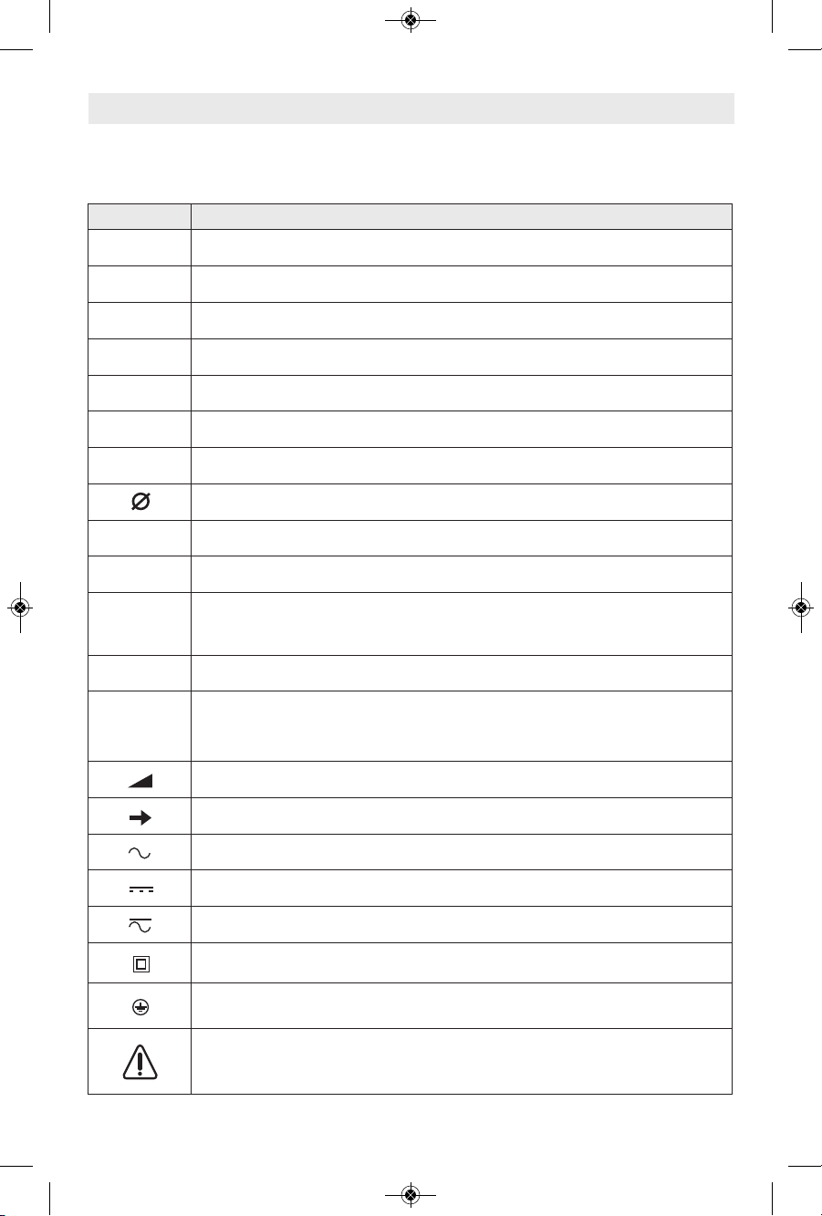
Symbols
IMPORTANT: Some of the following symbols may be used on your tool. Please study them
and learn their meaning. Proper interpretation of these symbols will allow you to operate the
tool better and safer.
Symbol Designation / Explanation
V Volts (voltage)
A Amperes (current)
Hz Hertz (frequency, cycles per second)
W Watt (power)
kg Kilograms (weight)
min Minutes (time)
s Seconds (time)
Diameter (size of drill bits, grinding wheels, etc.)
n
0
No load speed (rotational speed at no load)
n Rated speed (maximum attainable speed)
.../min
Revolutions or reciprocation per minute (revolutions, strokes, surface speed,
orbits etc. per minute)
0 Off position (zero speed, zero torque...)
1, 2, 3, ...
I, II, III,
Selector settings (speed, torque or position settings. Higher number means
greater speed)
0
Infinitely variable selector with off (speed is increasing from 0 setting)
Arrow (action in the direction of arrow)
Alternating current (type or a characteristic of current)
Direct current (type or a characteristic of current)
Alternating or direct current (type or a characteristic of current)
Class II construction (designates double insulated construction tools)
Earthing terminal (grounding terminal)
Warning symbol (alerts user to warning messages)
2610041372 09-15 GWS18V-45.qxp_GWS 9/18/15 10:00 AM Page 7
-8-
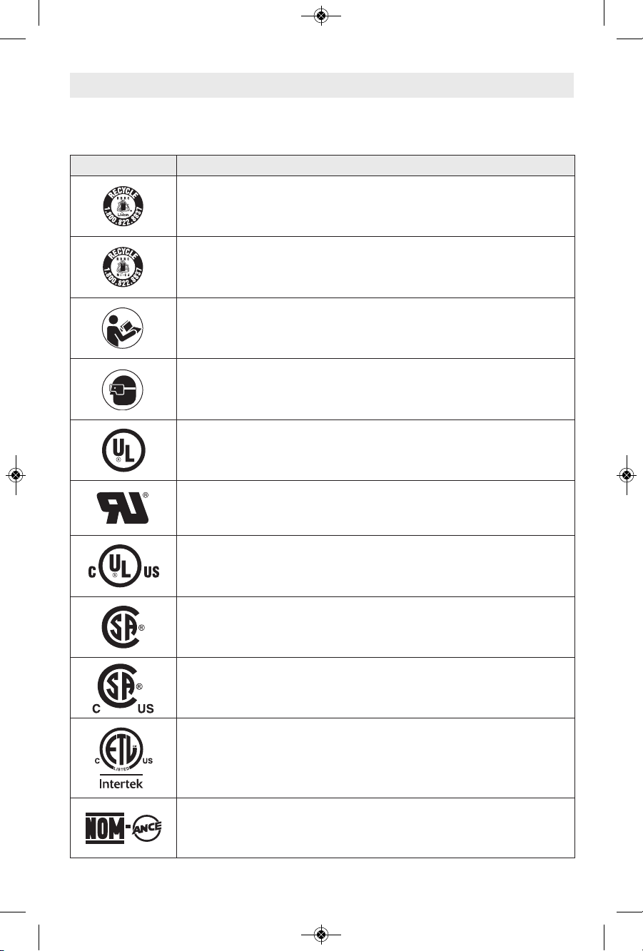
Symbols (continued)
IMPORTANT: Some of the following symbols may be used on your tool. Please study them
and learn their meaning. Proper interpretation of these symbols will allow you to operate the
tool better and safer.
Symbol Designation / Explanation
Designates Li-ion battery recycling program
Designates Ni-Cad battery recycling program
Alerts user to read manual
Alerts user to wear eye protection
This symbol designates that this tool is listed by Underwriters Laboratories.
This symbol designates that this component is recognized by Underwriters
Laboratories.
This symbol designates that this tool is listed by Underwriters Laboratories,
to United States and Canadian Standards.
This symbol designates that this tool is listed by the Canadian Standards
Association.
This symbol designates that this tool is listed by the Canadian Standards
Association, to United States and Canadian Standards.
This symbol designates that this tool is listed by the Intertek Testing
Services, to United States and Canadian Standards.
This symbol designates that this tool complies to NOM Mexican Standards.
2610041372 09-15 GWS18V-45.qxp_GWS 9/18/15 10:00 AM Page 8
-9-
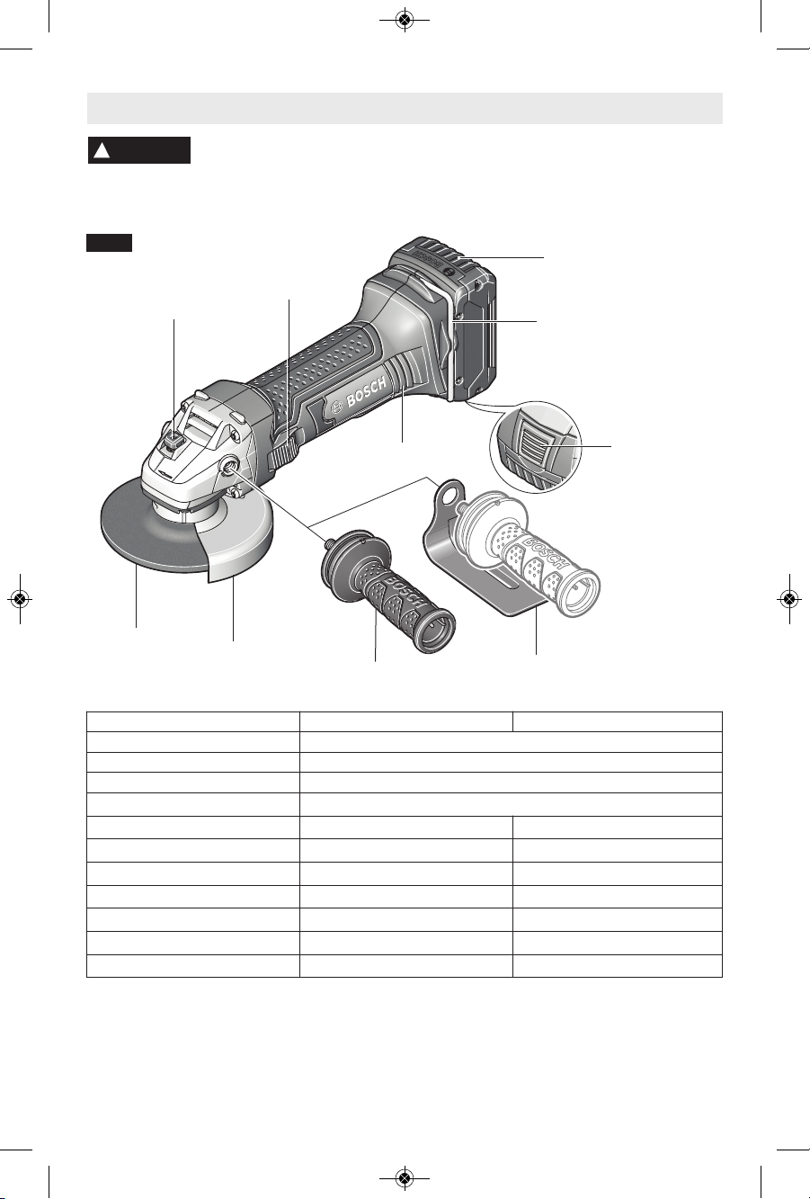
Functional Description and Specifications
Disco nne ct battery pa ck from tool bef ore ma king any assembl y,
adjustments or changing accessories. Such preventive safety measures
reduce the risk of starting the tool accidentally.
!
WARNING
Cordless Angle Grinder
VENTILATION
OPENINGS
GRINDING
WHEEL
WHEEL
GUARD
HAND GUARD
(Optional Accessory)
VIBRATION CONTROL
SIDE HANDLE
SPINDLE LOCK
FIG. 1
SLIDE
SWITCH
WRENCH AND
STORAGE AREA
BATTERY PACK
RELEASE BUTTON
BATTERY PACK
Battery Packs/Chargers
Please refer to the Charger Manual included
with your tool.
NOTE: For tool specifications refer to the
nameplate on your tool.
Accessory speed rating must be equal to or
greater than the tool’s speed rating. Do not
exceed the recommended wheel diameter.
NOTE: Not recommended for use with type
11 cup wheels.
Model number GWS18V-45 GWS18V-50
Battery 18V (Bosch Series)
Rated speed n 10,000/min
Spindle thread 5/8"-11 UNC
Max. spindle length 9/16" (14,3 mm)
Max.Type 27 grinding wheel ⌀ 4 1/2" (115 mm) 5" (125 mm)
Type 27 grinding wheel thickness 0.25" (6mm) 0.25" (6mm)
Max.Type 41/1A, 27A cutting wheel
⌀ 4 1/2" (115 mm) 5" (125 mm)
Max. flap disc ⌀ 4 1/2" (115 mm) 5" (125 mm)
Max. sanding disc ⌀ 4 1/2" (115 mm) 5" (125 mm)
Max. wire wheel ⌀ 4" (102 mm) 4" (102 mm)
Max. wire cup brush ⌀ 3" (76 mm) 3" (76 mm)
2610041372 09-15 GWS18V-45.qxp_GWS 9/18/15 10:00 AM Page 9
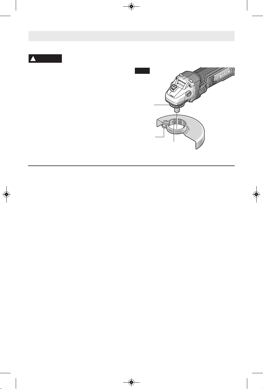
WHEEL GUARD INSTALLATION
Wh e el g uard mu s t b e
at tach ed when usi ng disc
grinding or cutting wheels. Always keep wheel
guard be tween yo u a nd your wo rk while
grinding or cutting.
The position of the guard can be adjusted to
accommodate the operation being performed.
To attach wheel guard, DISCONNECT battery
pack from tool.
Position guard on spindle neck so that the
notches on guard line up with the keys on the
spindle neck (Fig. 2).
Rotate guard either direction to desired position,
and tighten screw with the hex wrench provided
to secure guard in place.
TO REMOVE GUARD: Loosen screw with the
hex wrench provided, rotate guard until the
notches on guard line up with the keys on the
spindle neck, and lift guard off the spindle neck
(Fig. 2).
FIG. 2
Assembly
-10-
LOCK NUT AND BACKING FLANGE
Your tool is equipped with a threaded spindle
for mounting ac ces sories. Always use the
supplied lock nut (and backing flange) that
has same thread size as spindle.
VIBRATION CONTROL SIDE HANDLE
The side handle is used to control and balance
the tool. The handle must be thread ed into the
fr o nt h ousing on eith e r si d e o f the too l ,
de p endin g on per s o nal pre f erenc e an d
comfort. Use the side handle for safe control
and ease of operation (Fig. 1).
OPTIONAL HAND GUARD
(Optional Accessory)
The hand guard is to be used with backing
pads, sanding discs and wire brushes to keep
fingers and hand away from work surface,
sharp edges, burrs and debris. When using the
optional hand guard accessory insert side
handle through hole in guard and then thread
into housing (Fig. 1).
Ensure that hand guard is positioned between
hand and backing pad, sanding disc or wire
brush.
!
WARNING
KEYS
NOTCHES
SCREW
2610041372 09-15 GWS18V-45.qxp_GWS 9/18/15 10:00 AM Page 10
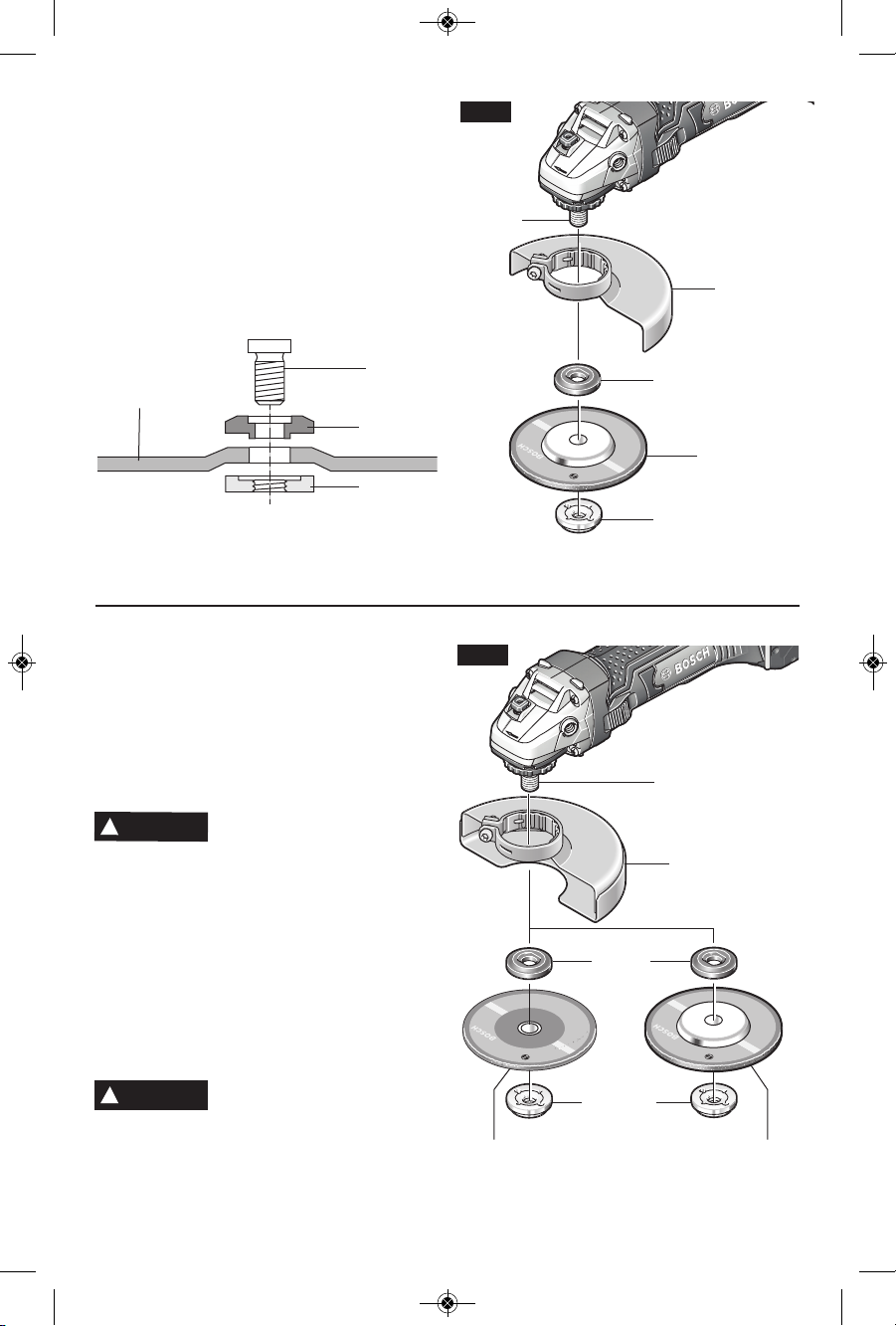
ABRASIVE TYPE 41/1A AND 27A
WHEEL ASSEMBLY
Using the optional Type 41/1A wheel guard,
it is possible to perform limited cutting on
small stock such as metal tubes, piping or
rebar.
Do not attempt to cut large stock or sheets of
metal as this tool is not designed to be a
dedicated cutting tool.
Al w ays use T ype 41/1 A
protection guard for cutting.
Disconnect battery pack from tool. Be sure
that wheel guard is in place for cutting.
When u s i n g mounting w h e e l s , thread
BACKING FLANGE onto spindle, then place
WHEEL on the spindle. Thread on the lock
nut and tighten ut using a lock nut wrench
provided with adapter kit, while holding the
spindle lock in (Fig. 4).
TO REMOVE: Reverse procedure.
TYPE 41/1A ABRASIVE
STRAIGHT GRINDING WHEELS
Do n o t use Typ e 4 1 /1A
abrasive wheels designed
for straight/die grinding. This tool is not
designed for use with Type 41/1A abrasive
straight/die grinding wheels.
!
WARNING
-11-
DISC GRINDING WHEEL ASSEMBLY
D
isconnect battery pack from tool. Be sure
that wheel guard is in place for grinding. Place
BACKING FLANGE and GRINDING WHEEL
on the spindle. Thread on the lock nut and
tighten nut using the supplied lock nut wrench,
while holding the spindle lock in (Fig. 3).
TO REMOVE: Reverse procedure.
No t rec o m m e nded fo r use w i t h spin- o n
wheels.
LOCK NUT
TYPE 27
GRINDING
WHEEL
BACKING
FLANGE
SPINDLE
TYPE 27
GRINDING
WHEEL
LOCK NUT
SPINDLE
TYPE 27
WHEEL GUARD
BACKING
FLANGE
FIG. 3
!
WA
RNING
TYPE 41/1A
WHEEL GUARD
SPINDLE
BACKING
FLANGE
TYPE 41/1A
CUTTING WHEEL
FIG. 4
LOCK NUT
TYPE 27A
CUTOFF
WHEEL
2610041372 09-15 GWS18V-45.qxp_GWS 9/18/15 10:00 AM Page 11
-12-
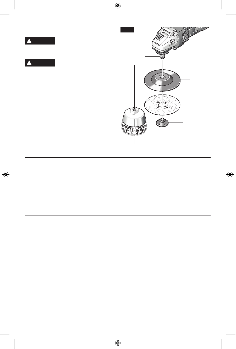
SANDING ACCESSORIES ASSEMBLY
B
ACKING PAD
Before attaching a backing
pad be sure its maximum safe
op erat ing spee d i s no t e xceed ed by t he
nameplate speed of the tool.
Wheel guard may not be used
for most sanding operations.
Always reinstall wheel guard when converting
back to grinding operations.
TO INSTALL BACKING PAD AND
SANDING DISC
Disconnect battery pack from tool.
Attach hand guard (Fig. 1). Set the tool on its
to p sid e (sp i n d l e up). Place the rubbe r
backing pad onto the spindle shaft. Center
the sanding disc on top of the backing pad.
Insert th e lo ck n ut t hrou gh t he d isc and
thread onto the spindle as far as you can
with your fingers. Press in the spindle lock,
then tighten the backing pad securely with
lock nut wrench (Fig. 5).
TO REMOVE: Reverse procedure.
!
WARNING
!
WARNING
SANDING
DISC
BACKING
PAD
LOCK NUT
WIRE
BRUSH
SPINDLE
FIG. 5
WIRE BRUSH ASSEMBLY
Before assembling wire brush to this tool,
disconnect from the power source. Attach
hand guard (Fig. 1). Wire br u s h e s are
equipped with their own threaded hub, simply
thread on to spindle. Be sure to seat against
shoulder before turning tool “ON”.
TO REMOVE: Reverse procedure.
WIRE WHEEL ASSEMBLY
Before assembling wire wheel to this tool,
disconnect from the power source. Attach type
27 guard (Fig. 2). Wire wheeels are equipped
with their own threaded hub, simply thread on
to spindle. Be sure to seat against shoulder
before turning tool “ON”.
TO REMOVE: Reverse procedure.
2610041372 09-15 GWS18V-45.qxp_GWS 9/18/15 10:00 AM Page 12
Operating Instructions
-13-
Hold the tool with both hands
while starting the tool, since
t
orque from the motor can cause the tool to twist.
Start the tool before applying to work and let
the tool come to full speed before contacting
the workpiece. Lift the tool from the work
before releasing the switch. DO NOT turn the
switch “ON” and “OFF” while the tool is under
load; this will greatly decrease the switch life.
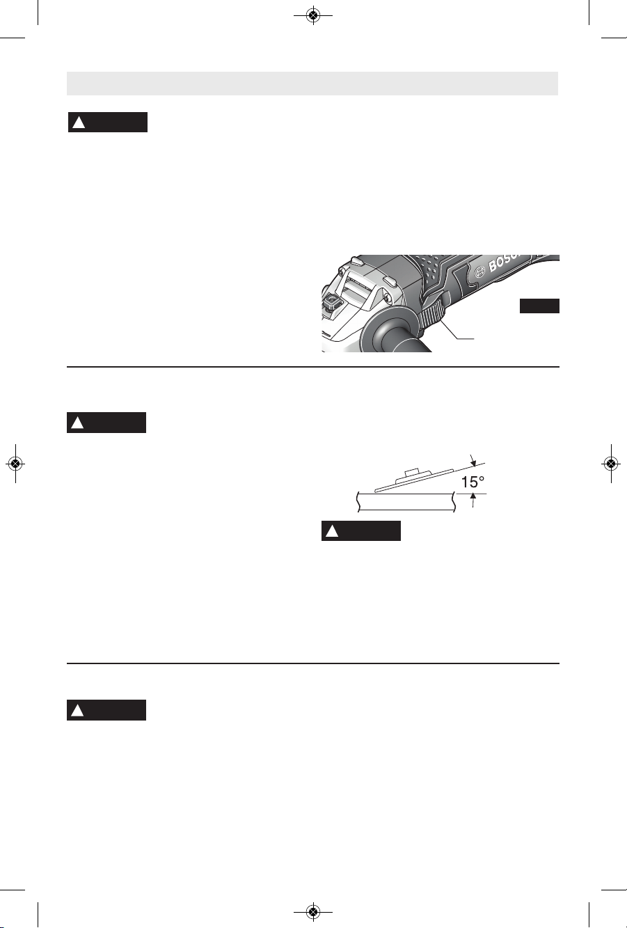
SLIDE ON-OFF SWITCH WITH LOCK
The tool is switched “ON” by the slide switch
located at the side of the motor housing. The
switch can be locked in the “ON” position, a
convenience for long grinding operations.
TO TURN THE TOOL “ON” without locking it,
move t h e switch f o rward b y applying
pressure ONLY at the REAR portion of the
switch. When pressure is released the switch
will return to “OFF” position (Fig. 6).
TO L OCK THE SWITCH “ON”, move the
switch forward and press the FRONT portion.
TO UNLOCK THE SWITCH, simply press
and release the REAR portion of the slider.
Switch is spring loaded and will snap back
automatically.
!
WARNING
SELECTING GRINDING WHEELS
Before using a grinding wheel,
be certain that its maximum
safe operating speed is not exceeded by the
nameplate speed of the grinder. Do not exceed
the recom mended wheel diameter.
DISC GRINDING WHEELS
Grinding wheels should be carefully selected in
order to use the grinder most efficiently. Wheels
vary in type of abrasive, bond, hardness, grit
size and structure. The correct type of wheel to
use is determined by the job. Use disc grinding
wheels for fast grinding of structural steel,
heavy weld beads, steel casting, stainless steel
and other ferrous metals.
GRINDING TIPS
Efficient grinding is achieved by controlling the
pressure and keep ing the angle between wheel
and workpiece at 10° to 15°. If the wheel is flat,
the tool is difficult to control. If the angle is too
steep, the pressure is concentrated on a small
area causing burning to the work surface.
Ex c essiv e or su d den
pressure on the wheel will
sl ow g rindi n g a c tion and put dan g erous
stresses on the wheel.
When grinding with a new wheel be certain to
grind while pulling tool backwards until wheel
becomes rounded on its edge. New wheels
have sharp corners which tend to “bite” or cut
into work piece when pushing forward.
!
WARNING
!
WARNING
SLIDE
SWITCH
FIG. 6
Grinding Operations
Cutting Operations
Do not use this grinder for
cutting masonry.
CUTTING METAL
Using the optional Type 41/1A wheel guard,
it is possible to perform limited cutting on
small stock such as metal tubes, piping or
rebar. When cutting, work with moderate
feed, adapted to the material being cut. Do
not exert side pressure onto the cutting disc,
tilt or oscillate the tool. When cutting profiles
and s quare b ar, it is best to st art at th e
smallest cross section.
Always follow precautions for kickback.
Do not apply side pressure to cutting wheel
to reduce wheel speed.
Th e to ol s houl d al ways be use d so tha t
sparks are directed away from user.
!
WARNING
2610041372 09-15 GWS18V-45.qxp_GWS 9/18/15 10:00 AM Page 13
-14-
Sanding Operations
SELECTING SANDING DISC
Sanding discs are made of extremely hard
and sharp aluminum oxide grits, phenol-resin
b
onded to a sturd y fiber back ing for fast
heavy-duty service and long life. The discs
vary as to size and spacing of the abrasive
grits. OPEN COAT (type H) — used for soft
materials and on paint or varnish. CLOSED
COAT (type K) —used for metal, hardwood,
stone, marble and other materials.
Sanding discs range in grit from 16 (very
coarse) to 180 (very fine). To obtain best
results, select sanding discs carefully. Many
jobs require the use of several grit sizes and
at times both “open coat and closed coat”
discs are required to get the job done faster.
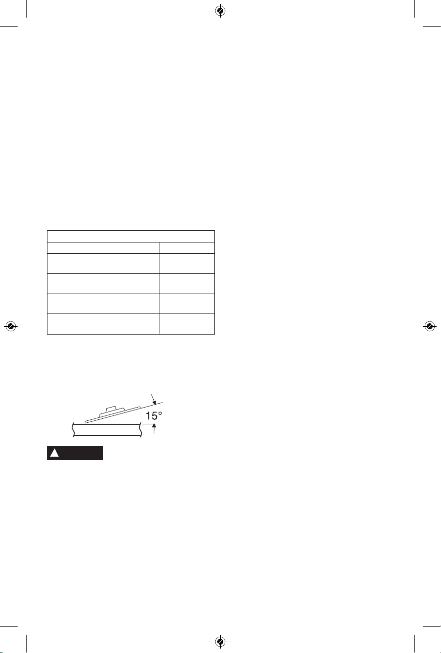
See chart for application examples.
Operation: Refinishing painted wood or metal surfaces.
REMARKS GRIT
To remove paint and to smooth Coarse
surface irregularities. 16-24-30
To smooth Medium
the rough sanding. 36-50-80
To remove scratches left by Fine
previous discs. 100-120
To smooth surfaces for painting, Very Fine
polishing or waxing. 150-180
SANDING TIPS
For best results, tilt the Disc Sander at a 10° to
15° angle while sanding so that only about 1"
of the surface around the edge of the disc
contacts the work.
If the disc (accessory) is held
flat or the back edge of the
disc comes in contact with the work, a violent
thrust to the side may result.
If sander is tilted too much, sanding action will
be to o g reat an d a ro u gh cut sur face or
gouging and snagging will result.
Guide the Disc Sander with crosswise strokes.
Be careful not to hold the sander in one spot
too long. Do not use a circular motion, as this
makes swirl marks. Test before use on scrap stock.
Do not force or apply pressure when sanding.
Use only the weight of the tool for pressure.
Excess pressure actually slows the tool down.
If faster stock removal is desired, change to a
coarser grit disc.
Remove gummy paint from metal with an
“open coat” disc. Sand until sparks start to
appear, then stop and change to a “closed
coat” disc to remove any remaining paint.
SANDING WOOD
When sanding wood the direction of the disc
motion at the contact point should parallel the
grain as much as possible. The rapid cut of
discs and the swirl type scratch pattern they
occasionally create generally prohibit their use
for producing the final finish.
Scratches and circular marks are usually the
re s ult of usin g too coars e a gr i t. When
changing to a finer grit, move across the sand ing lines that were made by a previous coarser
disc.
SANDING METAL
When sanding automobiles or appliances,
wipe the metal clean with a non-flammable
solvent or commercial cleaner to remove all
wa x an d g r ease. By doi ng t his first , th e
sanding discs will sand better and last longer.
For heavy duty work, use a coarse grit disc
first. Follow-up with a medium grit to remove
scratches. To produce smooth finish, use fine
grit disc.
!
WARNING
2610041372 09-15 GWS18V-45.qxp_GWS 9/18/15 10:00 AM Page 14

This tool is equipped with Automatic Restart
Pr o tecti o n. T his featu r e h e lps preve n t
accidental s tartups after power has been
interrupted, e.g. the battery was removed with
the switch locked in the on position. To resume
operation, turn the slide switch to the off
position, and back to on position to restart the
tool.
Make sure that the slide switch is in the off
position before inserting or removing battery
pack. (Fig. 6). To insert the battery pack slide
it into the housing until the battery pack locks
into position.
Your tool is equipped with a secondary locking
la t ch to pre v ent the ba ttery pack from
completely falling out of the handle, should it
become loose due to vibration.
To remove the battery pack, press the battery
pack release button and slide the battery pack
forward.
Press the battery pack release button again
and slide the battery pack completely out of
tool housing (Fig. 7).
FIG. 7
INSERTING AND RELEASING BATTERY PACK
-15-
Wire brushes are intended to “clean” structural
st e el, cas t ings, sheet metal , sto n e and
c
oncrete. They are used to remove rust, scale
and paint.
Avoid bouncing and snagging
th e w ire brush, es peci ally
when working corners, sharp edges etc. This
can cause loss of control and kick-back.
BRUSHING PRESSURE
1. Remember, the tips of a wire brush do the
work. Operate the brush with the lightest
pressure so only the tips of the wire come in
contact with the work.
2. If heavier pressures are used, the wires
will be overstressed, resulting in a wiping
action; and if this is continued, the life of the
brush will be shortened due to wire fatigue.
3. Apply the brush to the work in such a way
that as much of the brush face as possible is
in full contact with the work. Applying the side
or edge of the brush to the work will result in
wire breakage and shortened brush life.
!
WARNING
Wire Brush Operations
CORRECT:
Wire tips doing
the work.
INCORRECT:
Excessive
pressure can
cause wire
breakage.
CORRECT:
Wire tips doing
the work.
INCORRECT:
Excessive pressure
can cause wire
breakage.
WIRE WHEEL BRUSH
WIRE CUP BRUSH
2610041372 09-15 GWS18V-45.qxp_GWS 9/18/15 10:00 AM Page 15
 Loading...