

Bosch GWH C 800 ES, GWH C 800 CTDR EFS Installation Instructions Manual
GWH C 800 ES
(GWH C 800 CTDR EFS)
Temperature Modulated with Electronic Ignition
Suitable for heating potable water - Not approved for space heating purposes
(Intended for variable flow applications)
GWH C 800 ES - Natural Gas
GWH C 800 ES - Liquefied Petroleum (LP) Gas
6 720 608 643 US (2007.03) AL
Warning: If the information in this manual is not
followed exactly, a fire or explosion may result
causing property damage, personal injury or death.
Do not store or use gasoline or other flammable
vapors and liquids in the vicinity of this or any other
appliance.
Improper installation, adjustment, alteration,
service or maintenance can cause injury or
property damage. Refer to this manual. For
assistance or additional information consult a
qualified installer, service agency or the gas
supplier.
In the Commonwealth of Massachusetts this
product must be installed by a licensed plumber or
gas fitter.
Upon completion of the installation, these
instructions should be handed to the user of the
appliance for future reference.
What to do if you smell gas
• Close gas valve. Open windows.
• Do not try to light any appliance.
• Do not touch any electrical switch; do not use any
phone in your building.
• Immediately call your gas supplier from a neighbor’s
phone. Follow the gas supplier’s instructions.
• If you cannot reach your gas supplier, call the fire
department.
• Installation and service must be performed by a
qualified installer, service agency or the gas supplier.

6 720 608 643
2
Index
Index
1Warning 3
2 Appliance details 4
2.1 Features 4
2.2 GWH C 800 ES Specifications
(Technical data) 4
2.3 Unpacking the GWH C 800 ES heater 5
2.4 General rules to follow for safe operation 6
2.5 Dimensions and minimum installation
clearances 7
3 Installation instructions 8
3.1 Tools required for installation 8
3.2 Introduction 8
3.3 Proper location for installing your heater 8
3.4 Heater placement and clearances 8
3.5 Mounting installation 8
3.6 Gas piping & connections 10
3.7 Water connections 12
3.8 Water quality 12
3.9 Recirculation application 13
3.10 Filling the condensate trap 14
3.11 Combustion air requirements 15
3.12 Venting 16
3.13 Measuring gas pressure 26
4 Electrical connections 27
4.1 Electrical power supply 27
4.2 Position of the fuses in control unit 27
5 Operation instructions 28
5.1 Description LCD Display 28
5.2 For your safety read before operating
your water heater 29
5.3 Power 29
5.4 Temperature selection 29
5.5 Use of optional remote control accessory
(part no. TSTAT2) 30
5.6 Operation 30
5.7 Reset button 30
5.8 Program button 30
5.9 Locked condition 30
6 Maintenance and service 31
6.1 Annual maintenance 31
6.2 Winterizing for seasonal use 31
6.3 Mineral scale build-up 32
6.4 Condensing heat exchanger unit 33
6.5 Adjusting CO2 33
6.6 Program values 35
6.7 Control board diagnostics 36
7 Troubleshooting 37
7.1 Introduction 37
7.2 Burner does not ignite when hot water
is turned ON 37
7.3 Water is too hot 37
7.4 Water is not hot enough 37
7.5 Low water flow/pressure 38
7.6 Hot water temperature fluctuates at tap 38
7.7 Noisy burner/heater during operation 38
8 Problem solving 40
8.1 Error code diagnostics 40
9 Electrical diagram 45
10 Sensor resistance charts 46
11 GWH C 800 ES Functional scheme 48
12 Interior components diagram
and parts list 49
12.1 Interior components 49
12.2 Components diagram 51
13 Protecting the environment 58
14 Limited Warranty 59
6 720 608 643
Warning
3
1 Warning
For your safety
Do not store or use gasoline or other flammable,
combustible or corrosive vapors and liquids in the
vicinity of this or any other appliance.
FCC:
This device complies with Part 15 of the FCC rules.
Operation is subject to the following two conditions: (1)
This device may not cause harmful interference, and (2)
this device must accept any interference received,
including interference that may cause undesired
operation.
Fig. 1
Warning: Carefully plan where you
install the heater. Correct combustion
air supply and flue pipe installation are
very important. If a gas appliance is not
installed correctly, fatal accidents can
result such as, carbon monoxide
poisoning or fire.
Warning: Exhaust gas must be vented
to outside using approved vent material
See table 3, page 17 (For Canada use
only PVC ULCS636). Vent and
combustion air connector piping must
be sealed gas-tight to prevent
possibility of flue gas spillage, carbon
monoxide emissions and risk of fire,
resulting in severe personal injury or
death. Approved vent terminators must
be used when penetrating to the
outside.
Warning: Place the heater in a location
where water leaks will do NO DAMAGE
to adjacent areas or lower floors.
Warning: Field wiring connections and
electrical grounding must comply with
local codes, or in the absence of local
codes, with the latest edition of the
National Electric Code, ANSI/NFPA 70,
or in Canada, all electrical wiring must
comply with the local codes and the
Canadian Electrical Code, CSA C22.1
Part 1.
Warning: Shock hazard: line voltage is
present. Before servicing the water
heater, unplug power supply cord from
outlet. Failure to do so could result in
severe personal injury or death.
Warning: The heater must be
disconnected from the gas supply
piping system during any pressure
testing of that system at test pressures
equal to or more than 0.5 psig.

6 720 608 643
4
Appliance details
2 Appliance details
2.1 Features
Parts
• Key Pad interface control
• High power pre-mix compact burner with low NOx
emissions
• Modulating Gas Valve with constant gas:air ratio
control
• Modulating water valve for improved comfort and
temperature control.
High quality materials for long working life
• Copper heat exchanger
• High efficiency Ceramat Burner
• Compact space saver: mounts on a wall with a
supplied bracket.
Features
• Easily removable one-piece cover
• LCD Display with backlight
• On/Off and Temperature control switches
• Reset button
• Program button (Selectable temperature default)
• Failure codes for easy diagnostics and repair
• Real-time diagnostics for troubleshooting/informational purposes.
Accessories (Bosch part #)
• Optional wireless remote control to operate with the
appliance (TSTAT2)
• Cascading kit (TLINK)
•Outdoor kit (PTOK)
• External water filter (part # 8 703 305 356)
• Concentric termination kit (KGAVT0601CVT).
2.2 GWH C 800 ES Specifications
(Technical data)
Approved in US/Canada
Capacity
Maximum flow rate: 8.0 GPM (30 l/min) at a 45°F
(25°C) rise.
Maximum output
179,300 Btu/h (52.5 kW)
Maximum input
199,000 Btu/h (58.3 kW)
Efficiency in %
Thermal efficiency > 92%
Minimum Input
19,900 Btu/h (5.8 kW)
Temperature Control
Selection range: 100°F (38°C) - 140°F (60°C)
Default temperature: 122°F (50°C)
Stability: +/- 2°F (+/- 1°C)
Gas Requirement
Gas connection (inches) - ¾”
Inlet gas pressure under operation (with a high hot
water flow rate)*
• Propane: 9” - 14” water column
• Natural Gas: 4” - 14” water column.
* To measure Gas Pressure, see Measuring Gas
Pressure, chapter 3.13, page 26.
Water
• Hot water connection (inches) - ¾”
• Cold water connection (inches) - ¾”
• Water valve material: Polymer (PPS) (Polypropylene
Sulfid)
• Minimum water flow: 0.65 gallon/minute (2.5 l/m)
Note: Activation varies with inlet water temperatures
from 0.65 - 1.6 gallon/minute (2.5 - 6.1 l/m).
• Minimum recommended water pressure: 30 PSI
(2.07 bar)
• Minimum well pressure 40 psi, see page 12.
• Connections:
– Bottom of heater
Combustion
•NOx ≤ 55 ppm
•CO ≤ 250 ppm (air free)
•CO
2
level set from factory, see chapter 6.5, page 33.
i
BOSCH is constantly improving its
products, therefore specifications are
subject to change without prior notice.
6 720 608 643
Appliance details
5
Dimensions
• Depth (in): 11¼” (286 mm)
• Width (in): 17
7
/
8
” (452 mm)
• Height (in): 30½” (775 mm)
• Weight: 74 pounds (33.5 kg).
Gas types
Natural Gas.
LP Gas.
Voltage
120 V AC (60 Hz) nominal
Amperage
Idle - 40 mA
Operation - ≤ 2.5 A
Noise
45 - 65 db (A)
Safety devices
• Flame failure device (ionization flame rod sensor)
• Pressure relief valve (supplied with heater)
• Over heat prevention (temperature limiter)
• Inlet temperature sensor
• Outlet temperature sensor
• Back flow temperature sensor
• Exhaust gas temperature sensor.
Water protection
IP X4 (protection against water drops)
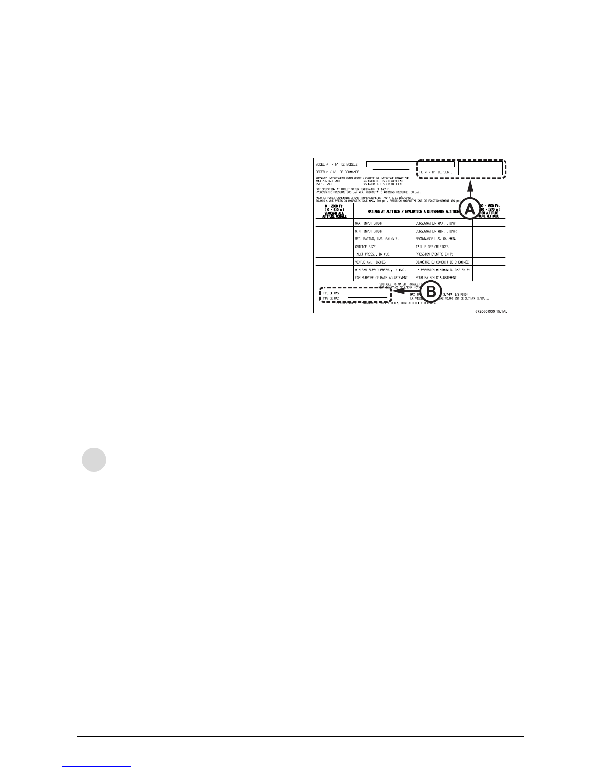
2.3 Unpacking the GWH C 800 ES
heater
Before installing the unit, be certain you have the
correct heater for your type of Gas - Propane or
Natural Gas. Identification labels are found on the
shipping box, and on the rating plate which is located on
the right side panel of the cover.
Fig. 2 Rating plate
A Serial number
B Type of gas
The box includes:
• GWH C 800 ES
• Pressure relief valve (150 psi / 200,000 Btu rating)
• Bracket for wall hanging the heater
• Exhaust vent adaptor (with 4 screws and gasket
provided)
• Combustion air inlet adaptor (with 3 screws and gas-
ket provided)
• Installation manual (manual can be downloaded at
www.boschpro.com)
• Product registration card
• Energy Guide label.
Please complete and return the enclosed product
registration card.
The GWH C 800 ES is not approved or designed
for:
• Manufactured (mobile) homes, boats or any
mobile installation.
• Use above 4500ft A.S.L. altitude.
• Outdoor installation without installation of
Outdoor kit (PTOK).
• Applications where inlet water temperature is
higher than 140°F (60°C). A 3-way valve or
mixing valve must be installed before the
appliance if inlet water temperature exceeds
this limit.
• Space heating purposes.
i
If appliance is installed at elevations
between 2000ft and 4500ft, a
combustion gas analyzer is required for
proper calibration of appliance. (see page
26).
6 720 608 643
6
Appliance details
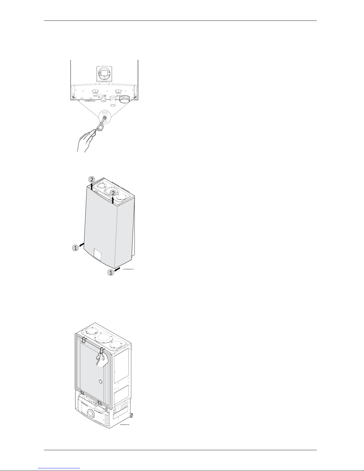
To remove front cover
B Loosen the two Philips head screws located on
bottom rear of cover (see Fig. 3).
Fig. 3 Loosen the two screws
B Lift front cover panel upward and remove.
Fig. 4 Remove the front cover
To remove combustion cover (service only)
B Open the four clips and remove the combustion
cover (see Fig. 5).
Fig. 5 Remove the combustion cover
2.4 General rules to follow for safe
operation
B 1. You must follow these instructions when you
install your heater. In the United States: The
installation must conform with local codes or, in the
absence of local codes, the National Fuel Gas Code
ANSI Z223.1/NFPA 54.
In Canada: The Installation must conform with CSA
B149.(1,2) INSTALLATION CODES and /or local
installation codes.
B 2. Carefully plan where you install the heater. Correct
combustion air supply and vent pipe installation are
very important. If not installed correctly, fatal
accidents can occur, such as carbon monoxide
poisoning or fire.
B 3. When the unit is installed indoors and ROOM
SEALED (twin pipe) it is permitted to be located in
bathrooms, bedrooms and occupied rooms that are
normally kept closed. See chapter 3.12 (page 16). If
the unit will be installed indoors and use indoor
combustion air, the place where you install the heater
must have enough ventilation. The National Fuel
Gas Codes do not allow UNSEALED gas fired
water heater installations in bathrooms,
bedrooms or any occupied rooms normally
kept closed. See chapter 3.11 (page 15).
B 4. You must correctly vent your heater. See
chapter 3.12 (page 16) on VENTING.
B 5. The appliance and its gas connection must be leak
tested before placing the appliance in operation.
The appliance must be isolated from the gas supply
piping system by closing its individual manual gas
shutoff valve (not supplied with heater) during any
pressure testing at pressures in excess of ½ Psig
(3.5 kPa).
B 6. Keep water heater area clear and free from
combustibles and flammable liquids. Do not locate
the heater over any material which might burn.
B 7. Correct gas pressure is critical for the proper
operation of this heater. Gas piping must be sized to
provide the required pressure at the maximum output
of the heater, while all the other gas appliances are in
operation. Check with your local gas supplier, and
see the section on connecting the gas supply. See
chapter 3.6 (page 10).
B 8. Should overheating occur or the gas supply fail to
shut off, turn off the gas supply at the manual gas
shut off valve, on the gas line. Note: manual gas
shutoff valve is not supplied with the heater but must
be field installed.
B 9. Do not use this appliance if any part has been
underwater. Immediately call a qualified service
technician to inspect the appliance and to replace
any part of the control system and any gas control
which has been underwater.
B 10. Failure to install heater correctly may lead to
unsafe operation and void the warranty.
6 720 608 643
Appliance details
7
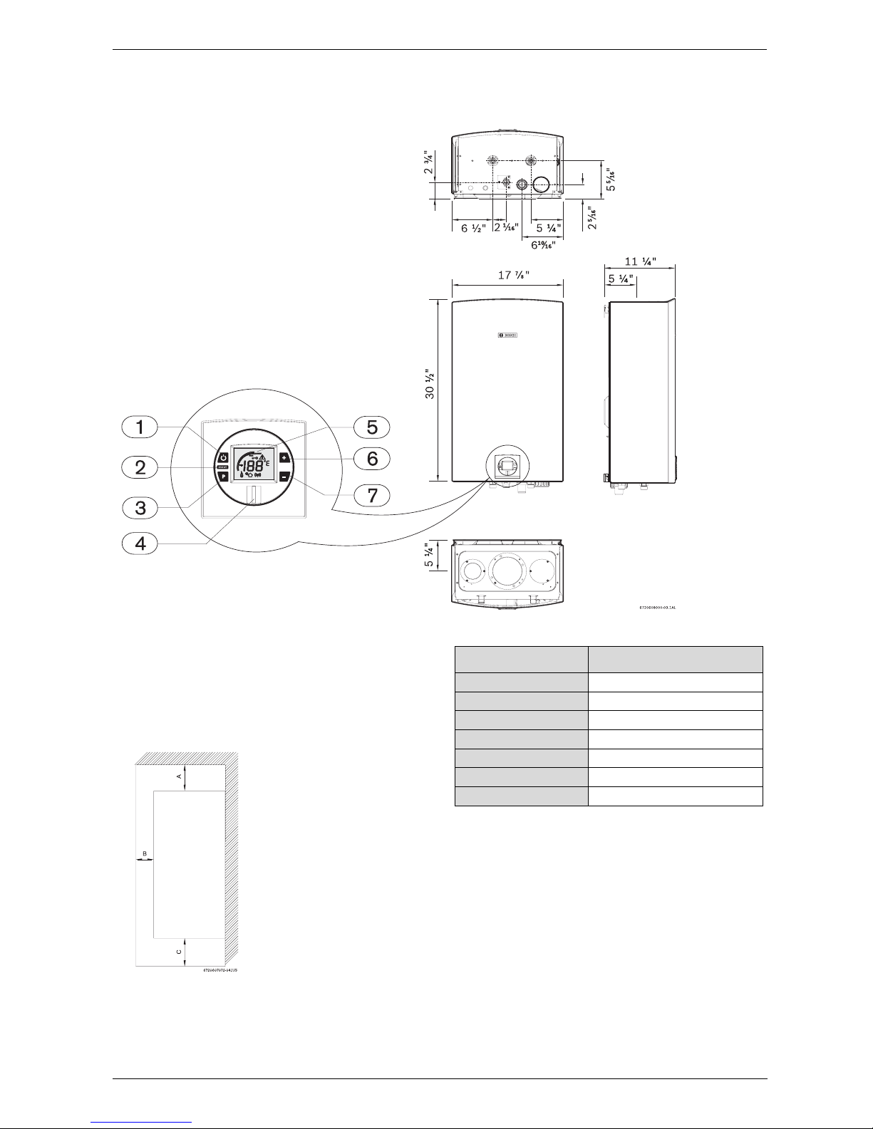
2.5 Dimensions and minimum installation clearances
Fig. 6 Dimensions
1 On/Off button
2 Reset button
3 Program key
4 Power ON or stand-by LED
5 LCD display
6 Up button
7 Down button
Fig. 7 Minimum clearances
Note: For servicing access, a 2ft clearance is
recommended to the front cover.
Note: Consult vent manufacturer for specific clearance
information
Model GWH C 800 ES
TOP (A) 12”
FRONT (B) 1”
BACK 0”
SIDES 1”
FLOOR (C) 12”
VENT DIAMETER 3”
VENT CLEARANCES 0”
Table 1 Minimum clearances

6 720 608 643
8
Installation instructions
3 Installation instructions
3.1 Tools required for installation
• Philips head screwdriver
• Flat head screwdriver
• Adjustable wrench
• Level
• Thermometer
• Standard plumbing tools
•Manometer.
3.2 Introduction
Please follow these instructions. Failure to follow
instructions may result in:
B Damage or injury.
B Improper operation.
B Loss of warranty.
If you are unable to perform the tasks required to install
this heater properly, please contact a locally licensed
plumber or gas technician.
3.3 Proper location for installing your
heater
Carefully select the location of the water heater. For
your safety and for proper heater operation, you must
provide combustion air to the heater and a proper
exhaust vent system.
Follow the guidelines below:
B 1. Locate the heater where venting, gas and
plumbing connections are feasible and convenient.
B 2. The hot water lines should be kept short and
insulated to save energy. Centrally locating the water
heater is recommended to keep hot water
distribution times even throughout the structure.
3.4 Heater placement and clearances
The GWH C 800 ES design is approved for
installation on a combustible wall (see chapter 3.5
Mounting installation) provided the floor
covering below the heater is noncombustible.
For installations in an alcove or closet, maintain the
minimum clearances to combustible and noncombustible materials listed below. See also Fig. 7,
page 7.
A. Top 12 inches (306 mm)
B. Front 1 inches (25 mm)
C. Back 0 inches
D. Sides 1 inches (25 mm)
E. Bottom 12 inches (306 mm)
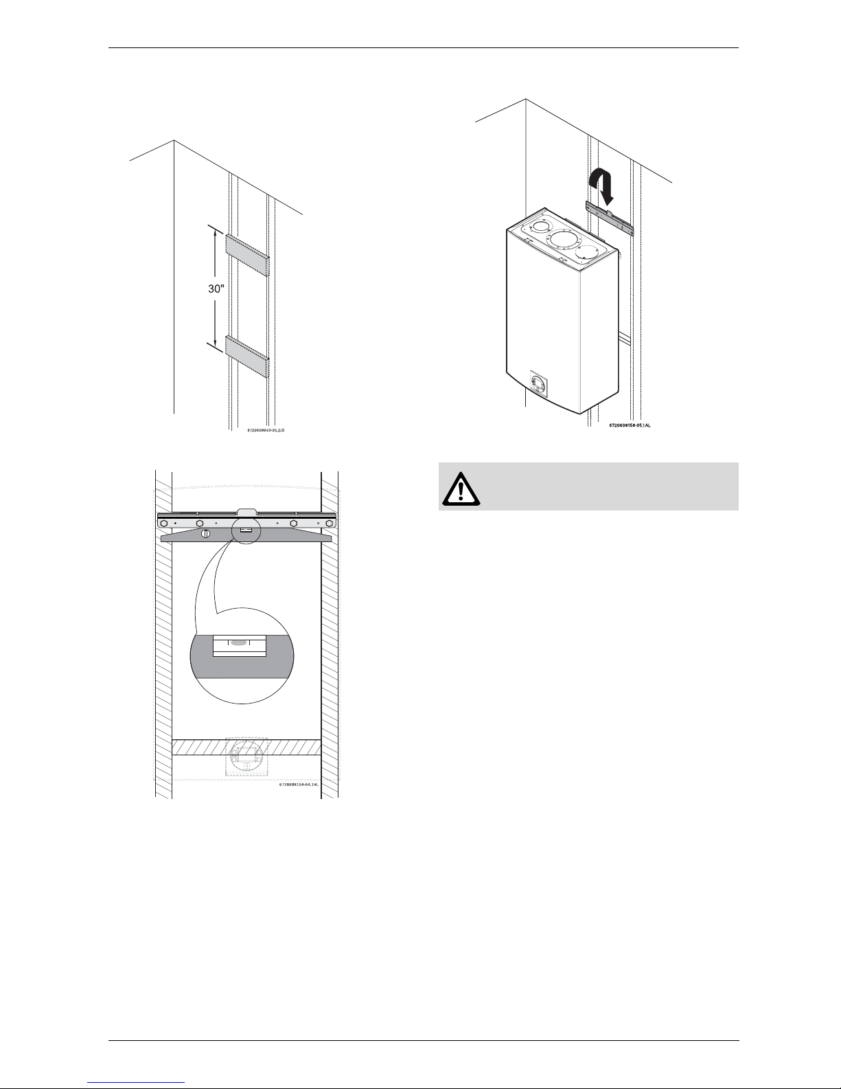
3.5 Mounting installation
If wall is sheathed with plaster or drywall, it is
recommended that two support boards, either 1”x4” or
1/2" (minimum) plywood first be attached across a pair
of studs, see Fig. 8, page 9.
B Secure the wall mounting bracket provided with the
heater to a wall surface. The heater must be kept
level on the wall surface, see Fig. 9, page 9.
Warning: The water in this water
heater is cold and always remains cold
except for the times the burner is on. In
the event of power outage in
conjunction with freezing temperatures,
it is recommended that the heater be
drained.
See chapter 6.2, page 31 “Winterizing”
for draining instructions.
Warning: Flammable materials,
gasoline, pressurized containers, or any
other items or articles that are potential
fire hazards must NOT be placed on or
adjacent to the heater. The appliance
area must be kept free of all
combustible materials, gasoline and
other flammable vapors and liquids.
Warning: before starting installation:
B Check that there are no loose parts
inside the appliance
B Confirm that the gas type of the
heater matches the gas supply you
will be connecting the heater, See
Fig. 2, page 5.
B Ensure that gas pipe, gas valve,
mixer, fans and burner have no
damage and are properly fitted.
i
Front cover should be removed (see
instructions on page 6) in order to inspect
components visually.
Warning: Do not install this appliance
on a carpeted wall. The heater must be
mounted on a wall using appropriate
anchoring materials.
6 720 608 643
Installation instructions
9
B Hang the appliance on the bracket, see Fig. 10, page
10.
Fig. 8 Distance between support boards
Fig. 9 Leveling wall mounting bracket
Fig. 10 Mounting the heater
Studs 16"
(406mm) on
center
Warning: Appliance must be installed
vertically.
6 720 608 643
10
Installation instructions
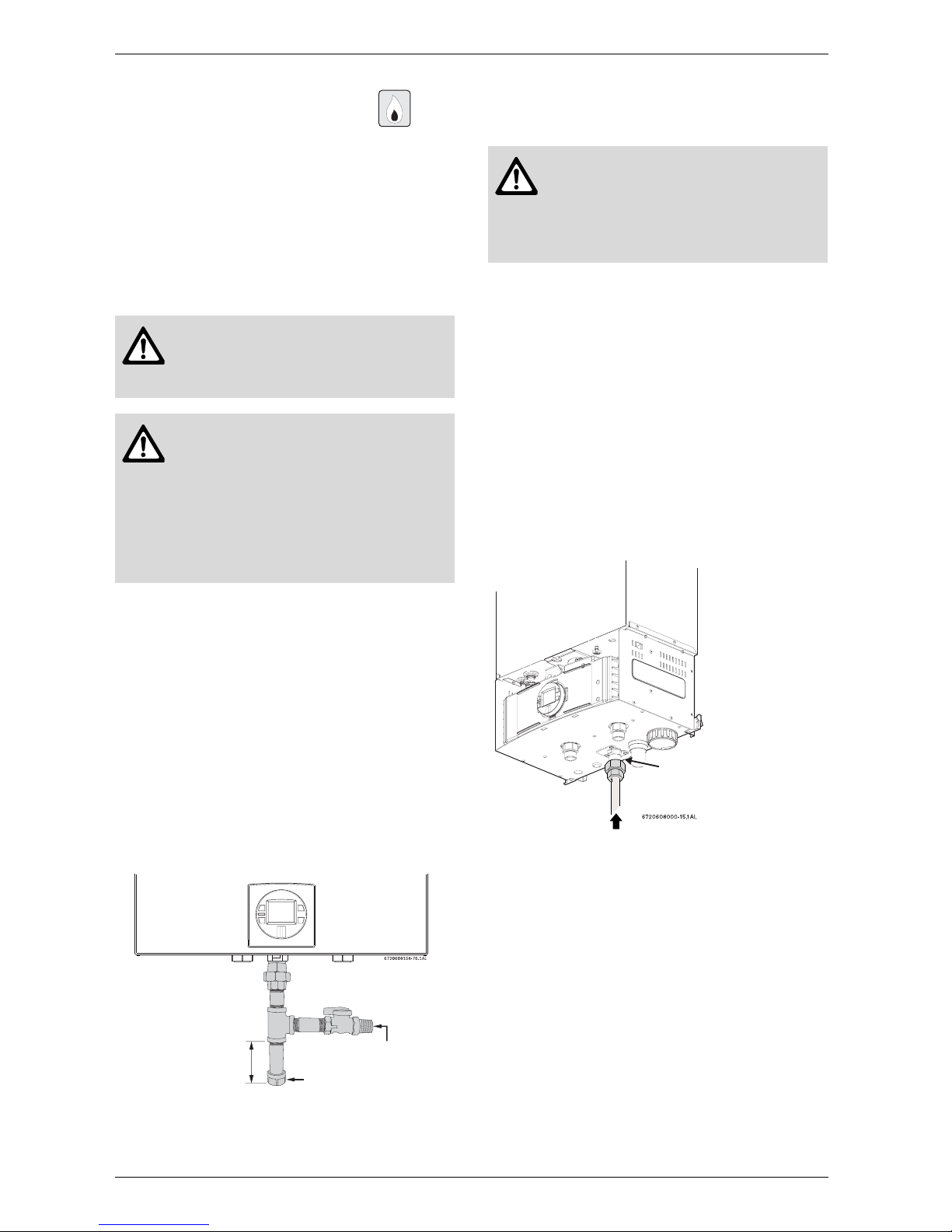
3.6 Gas piping & connections
Before connecting the gas supply, check the rating
plate on the right side of the heater to be sure that the
heater is rated for the same gas to which it will be
connected.
In the United States: The installation must conform with
local codes or, in the absence of local codes, the
National Fuel Gas Code ANSI Z223.1/NFPA 54.
In Canada: The Installation must conform to CGA B149
INSTALLATION CODES and/or local installation
codes.
GAS CONNECTIONS
B Install a manual gas shut off valve on the gas supply
line.
B Install a union when connecting gas supply.
B The minimum internal diameter required for
any appliance connector is ¾”, see Fig. 13 for
more details on pipe sizing.
B National Fuel Gas Code requires that a sediment
trap (drip leg) be installed on gas appliances not so
equipped. The drip leg must be accessible and not
subject to freezing conditions. Install in accordance
with the recommendations of the serving gas
supplier, see Fig. 2.
Fig. 11 Gas connection
Once connections are made, check for gas leaks at all
joints. Apply some gas leak detection solution to all gas
fittings. Bubbles are a sign of a leak. A combustible gas
detector may also be used to detect for leaks.
GAS LINE SIZING
The gas supply piping for a single heater should be
sized for a maximum draw of 199,000 BTUH. Measure
the length of gas supply line from the building's gas
main to the heater and use the tables in Fig. 13, page
11 or the gas line manufacturer’s sizing tables to
determine the pipe diameter necessary. If there are
more gas drawing appliances on the line, size the gas
line according to the total maximum amount of BTU
draw input rating of for all appliances combined.
Note: Undersizing the gas line may result in diminished
hot water flow rate and temperature. See chapter 3.13,
page 26 for the procedure to measure gas pressure.
Proper gas pressure must be confirmed at time of
installation.
Fig. 12
Warning: DO NOT connect to an
unregulated or high pressure propane
line or to a high pressure commercial
natural gas line.
Warning: The heater must be isolated
from the gas supply piping system
during any pressure testing of that
system at test pressures equal to or
more than 0.5 psig. If overpressure has
occurred, such as through improper
testing of the gas lines or malfunction of
the supply system, the gas valve must
be checked for safe operation.
Gas supply
Cap
Minimum
3”
Danger: If you have a leak, shut off the
gas. Tighten appropriate fittings to stop
leak. Turn the gas on and check again
with a gas leak detection solution.
Never test for gas leaks using a match
or flame.
Gas piping
Inlet gas particle screen
(included)
6 720 608 643
Installation instructions
11
FOR NATURAL GAS
Maximum Capacity of pipe in Cubic Feet of Gas per Hour for Gas Pressure of 0.5 Psig or less and a Pressure drop
of 0.3” in Water Column (0.75mbar).(Based on a 0.60 Specific Gravity Gas) Btu numbers given in thousands.
Fig. 13
Follow boxed numbers for piping just one GWH C 800 ES (example: ¾” B.I. Natural Gas pipe for 10 ft
(3.0m). will handle 278,000 btu’s (81.5 kWh). For multiple appliances combine the total maximum btu input
load and then refer to applicable chart below.
* EHD = Equivalent Hydraulic Diameter. The greater the
value of EHD, the greater the gas capacity of the tubing
.
Maximum Capacity of Semi-Rigid (flexible, non
corrugated) Tubing in Thousands of BTU per Hour of
Undiluted Liquefied Petroleum Gases (at 11 inches
Water Column Inlet Pressure).
(Based on a Pressure Drop of 0.5 Inch Water Column)
* Source National Fuel Gas Code NFPA 54, ANSI
Z223.1 - No Additional Allowance is necessary for an
ordinary number of fittings
FOR LP GAS
Maximum Capacity of Pipe in Thousands of BTU per Hour of Undiluted Petroleum Gases (at 11 inches Water Column Inlet
Pressure) (Based on a Pressure Drop of 0.5 Inch Water Column).
* EHD = Equivalent Hydraulic Diameter. The greater the
value of EHD, the greater the gas capacity of the tubing.
Nominal
Iron
Length of Black iron Pipe , Feet
Pipe Internal
Size, Diameter
inches inches 10 20 30 40 50 60 70 80 90 100 125 150 175 200
1/4 0.364 32 22 18 15 14 12 11 11 10 9 8 8 7 6
3/8 0.493 72 49 40 34 30 27 25 23 22 21 18 17 15 14
1/2 0.622 132 92 7363 56504643403834 312826
3/4 0.824 278 190 152 130 115 105 96 90 84 79 72 64 59 55
1 1.049 520 350 285 245 215 195 180 170 160 150 130 120 110 100
1 1/4 1.380 1050 730 590 500 440 400 370 350 320 305 275 250 225 210
1 1/2 1.610 1600 1100 890 760 670 610 560 530 490 460 410 380 350 320
2 2.067 3050 2100 1650 1450 1270 1150 1050 990 930 870 780 710 650 610
Tube
size,
inches EHD*
10 20 30 40 50 60
1/2 18 EH
D
82 58 47 41 37 34
3/4 23 EH
D
161 116 96 83 75 68
1 30 EH
D
330 231 188 162 144 131
1 1/4 37 EH
D
639 456 374 325 292 267
Length of Flexible Corrugated Stainless Steel Tubing (CSS T), Feet
Tube
size
inches EHD*
10 20 30 40 50
1/2 18 EHD 129 91 74 64 58
3/4 23 EHD 254 183 151 131 118
1 30 EHD 521 365 297 256 227
Lengt h o f Flexible Corrugated Stainless Steel Tubing (CSST),
F
Nominal
iron
Black Iron Pipe
pipe
Length of Pipe, Feet
Inches
10 20 30 40 50 60 80 100 125 150 200
1/2 291 200 160 137 122 110 94 84 74 67 58
3/4 608 418 336 287 255 231 197 175 155 140 120
1 1145 787 632 541 480 434 372 330 292 265 227
Copper
Outside Length of Tubing, Feet
diameter
Inch 10 20 30 40 50 60 70 80 90 100
3/8 39 26 21 19 _ _____
1/2 9262 50 41 37 3531292726
5/8 199 131 107 90 79 72 67 62 59 55
3/4 329 216 181 145 131 121 112 104 95 90
6 720 608 643
12
Installation instructions
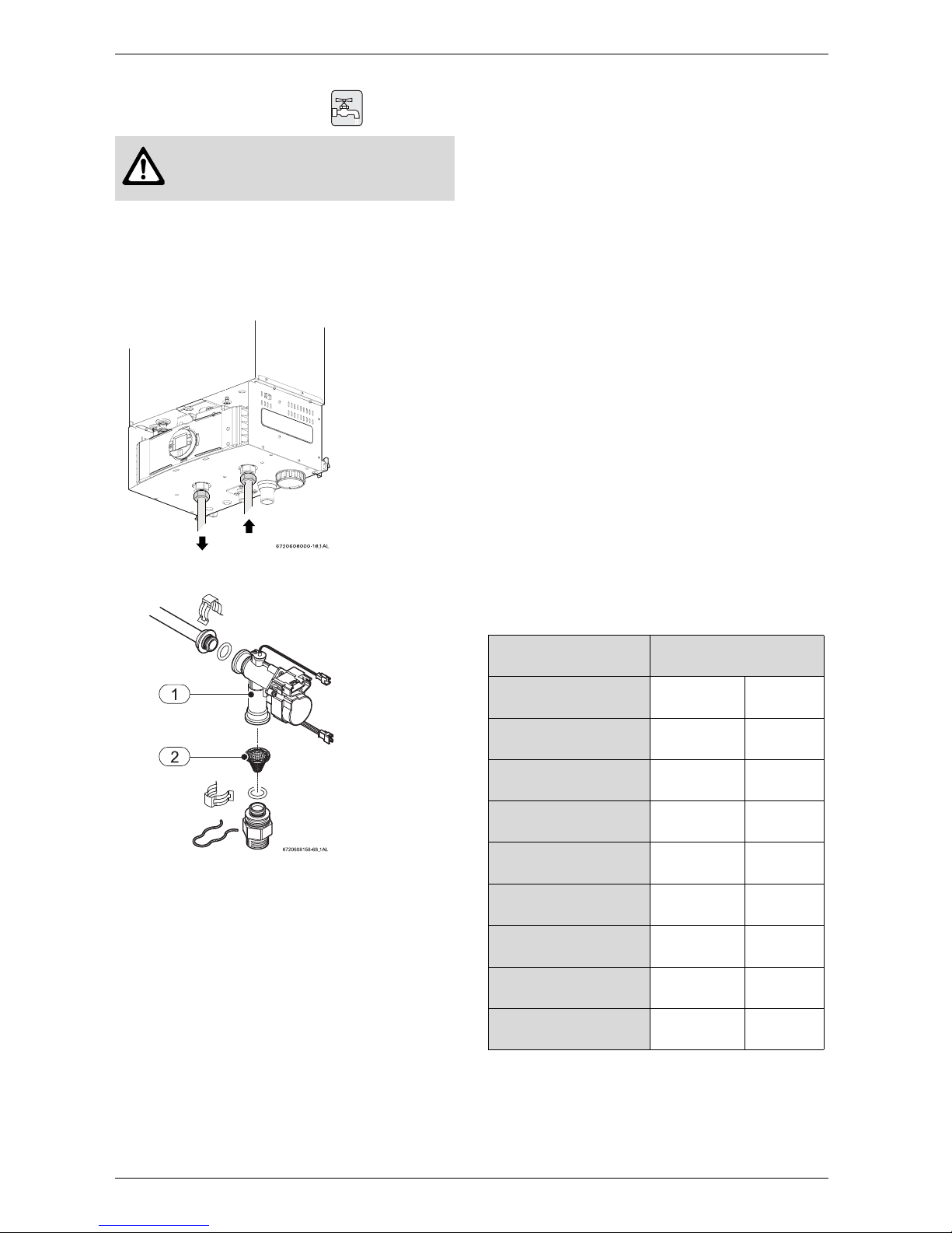
3.7 Water connections
B When facing the heater, the ¾” cold connection is on
the bottom right and the hot connection is on the
bottom left. Centrally locating the water heater is
recommended to keep hot water distribution times
even throughout the structure.
Fig. 14
Fig. 15 Water filter
1 Water valve with engine
2 Water filter
B The use of unions when connecting both water
pipes to the inlet and outlet connections is
required. This will facilitate any necessary
servicing.
B Plastic or PEX type plumbing line materials are not
suitable for connecting directly to the water heater.
B Although water piping throughout the building may
be other than copper, we recommend that copper or
suitably rated stainless steel flex line piping be used
for the water connections for 1.5’ on either side of
the water heater (follow local codes if more
stringent).
B Never sweat any piping directly to or beneath
the water connections, as damage will occur to
the internal water valve from heating of the
pipe.
B Keep water inlet and outlet pipes to no less
than ¾" (19.05mm) diameter to allow the full
flow capacity.
B If the cold and hot connections to the heater are
reversed, the heater will not function. Be certain there
are no loose particles or dirt in the piping. Blow out
or flush the lines before connecting to the water
heater.
B Full port shutoff valves should be installed on
both the cold water supply and hot water outlet
lines to facilitate servicing the heater (see Fig.
16).
B For installation on a private well system with the use
of a pressure tank, the lowest pressure range setting
recommended is 40-60 psi (2.75 - 4.15bar).
3.8 Water quality
Water quality can have an impact on appliance
longevity and may void the manufacturer's warranty.
For water analysis data call your local water department,
or if on a well, have well water analyzed periodically. If
water quality exceeds one or more of the values
specified below, Bosch recommends installing a water
conditioner or softener.
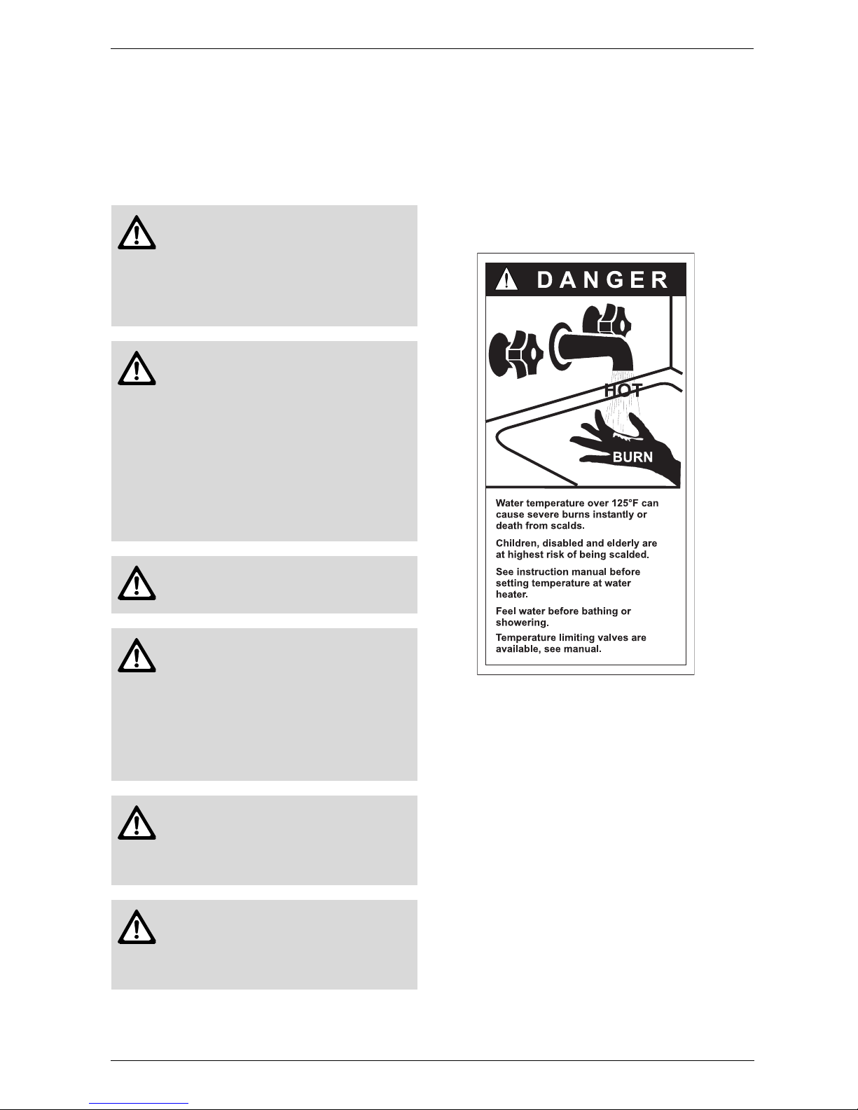
Warning: This heater is not approved
for preheated water applications
exceeding 140°F (60°C).
HOT COLD
Description Max. Levels
pH pH 6.5 - 8.5
TDS (total Dissolved
Solids)
mg/l or ppm 500
Total hardness mg/l or ppm
100
(6 grains)
Aluminum mg/l or ppm 2.0
Chlorides mg/l or ppm 250
Copper mg/l or ppm 1.0
Iron mg/l or ppm 0.3
Manganese mg/l or ppm 0.05
Zinc mg/l or ppm 5.0
Table 2
6 720 608 643
Installation instructions
13
Connecting the pressure relief valve (PRV)
A listed pressure relief valve supplied with the heater
must be installed at the time of installation. No valve is
to be placed between the PRV and the heater. No
reducing coupling or other restriction may be installed
in the discharge line. The discharge line must be a
minimum of 4” above a drain and installed such that it
allows complete drainage of both the PRV and the line.
The discharge line must be placed where it will not
cause any damage.
The location of the PRV must be readily accessible for
servicing or replacement, and be mounted as close to
the water heater as possible. See Fig. 16. To install the
PRV, a suitable fitting connected to an extension on a
“T” fitting can be sweated to the hot water line.
Support all piping.
Fig. 16 Plumbing Connections (with shutoff valves)
and Pressure Relief Valve
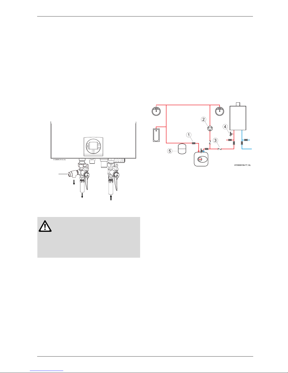
3.9 Recirculation application
The GWH C 800 ES Protankless water heater is
approved for domestic hot water recirculation. The
following drawing is provided to outline one possible
recirculation design using the water heater in
conjunction with an Ariston mini tank water heater.
Recirculation directly through the tankless water heater
is also allowed. This schematic is for illustration only and
must not be used for actual Installation without
appropriate engineering and technical advice from a
properly licensed professional in the locality where the
installation is made.
Fig. 17 Recirculation application
1 Full port isolation valve
2 Circulator pump on timer
3 Check valve
4 PRV
5 Expansion tank
The use of a small electric mini-tank after heater (4-6
gallon size) should be used for this application and
designed so the pump will circulate the water through
the mini-tank and the building's hot water return loop
only. Timed or thermostatically controlled operation of
the pump is commonly done. Contact Bosch Water
Heating if further information is needed.
Warning:
In applications where inlet water
temperature can exceed 140°F (60ºC), a
3-way valve or mixing valve must be
installed before the appliance to prevent
water exceeding 140°F (60°C) from
entering the appliance.
Pressure
relief
valve
Ariston Minitank
GWH
C 800
ES
6 720 608 643
14
Installation instructions
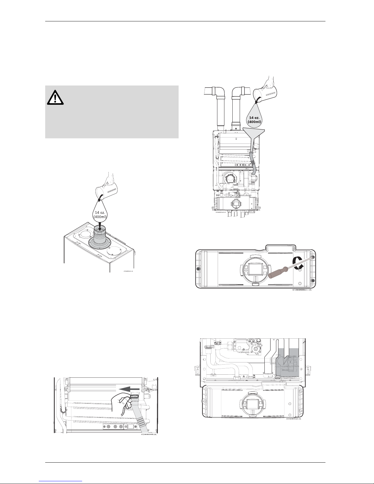
3.10 Filling the condensate trap
The condensate trap can be filled before or after
connecting the vent pipe.
Filling the condensate trap before vent pipe
installation
B Fill the condensate trap by pouring approx.14 oz.
(400ml) of water into the exhaust accessory on the
top of the appliance, see Fig. 18.
Fig. 18 Filling the condensate trap at start up
Filling the condensate trap after vent pipe
installation
After appliance has been out of use for a long time or
after cleaning siphon, refill the condensate trap with
water.
Please proceed as follows:
B Remove front cover, see Fig. 4, page 6.
B Open the four clips and remove the combustion
cover, see Fig. 5, page 6.
B Remove the clip and disconnect the drain tube, see
Fig. 19.
Fig. 19 Disconnect drain tube
B Fill the condensate trap by pouring approx.14 oz.
(400ml) of water into the top of the drain tube. To
avoid damage to the appliance use a funnel in this
operation, see Fig. 20, page 14.
Fig. 20 Filling the condensate trap after installation
B Loosen the three screws of the control unit.
Fig. 21
B Put the control unit in service position by engaging its
tabs with the holes in the bottom horizontal sheet
metal, see Fig. 22.
B Check water level in the condensate trap.
Fig. 22 Water level in condensate trap
B After filling reassemble all parts in reverse order.
Danger: Prior to initial start up, and
after appliance has been out of use for a
long time or after cleaning the sifon,
make sure that you fill the condensate
trap with water. This is to prevent
dangerous exhaust gases from entering
the building.
6 720 608 643
Installation instructions
15
3.11 Combustion air requirements
Twin pipe
The GWH C 800 ES is designed as a sealed
combustion appliance. It is recommended that the
combustion air be provided by a dedicated 3” or 4” pipe
from the outside. The combustion air pipe may be PVC
or any other rigid or semi rigid sealed 3” or 4” pipe. The
combustion air piping must pitch down 1/4 inch per
foot towards termination to prevent rain water from
entering the appliance. The combustion air inlet,
whether terminating vertically or horizontally, must be
located in such a manner as to provide a
minimum 3 foot clearance from the exhaust vent
terminator. See Fig. 36 Letter I, page 24.
The maximum length of the combustion air inlet
is 26 feet with one elbow. Subtract 5 feet for each
additional 90° elbow and 3 feet for each
additional 45° elbow. Maximum number of 90°
elbows permitted is 3.
Single pipe
Note: This appliance requires 9950 cubic feet of
available combustion air, or a minimum of 1243 square
feet of space with an 8 foot ceiling to operate. If the
large amount of air space, which equates to about half
of most average sized homes, is not available, the
appliance must pull air from the outside (see twin pipe
above).
Although it is permissible to draw combustion air from
the inside, it is not the manufacturer’s recommended
installation method. Always install a 3 inch 90° elbow on
the top of the combustion air inlet adaptor to prevent
foreign objects from falling into the unit.
If a single pipe installation is utilized, follow guidelines
below for providing adequate combustion air for the
water heater as well as any other appliances that may
consume air in the same space. Always follow local
codes if they are more stringent and regulations.
• Appliances located in unconfined spaces:
– a) An unconfined space is one whose volume is
greater than 50 cubic feet (1.42 cubic meter) per
1000 Btu per hour (292.81 Watts) of the
combined rating of all appliances installed in the
space. That would be 9950 cubic feet (281.8
cubic meters) for the GWH C 800 ES alone.
– b) In unconfined spaces in buildings of
conventional frame, masonry, or metal
construction, infiltration air is normally adequate to
provide air for combustion.
• Appliances located in confined spaces:
The confined space must be provided with two permanent openings, one commencing within 12 inches
(304.8mm) of the top and one commencing within
12 inches (304.8mm) of the bottom of the enclosure.
Each opening must have a minimum free area of one
square inch per:
– 1000 Btu/hr (292.81 Watts) if all air is taken from
inside the building
– 2000 Btu/hr (585.62 Watts) if all air is taken from
the outside by horizontal ducts
– 4000 Btu/hr (1171.24 Watts)if all air is taken from
the outside by direct openings or vertical ducts
Or the confined space must be provided with one
permanent opening or duct that is within 12 inches
(304.8mm) of the ceiling of the enclosure. This opening
must have a minimum free area of one square inch per:
– 3000 Btu/hr (878.43 Watts) if all air is taken from
the outside by a direct opening or vertical duct.
Louvers, grills and screens have a blocking effect, when
used, increase the sizes of your openings by 300% for
wood louvers (as wood type will reduce the free air by
75%) and 43% for metal louvers (as metal will reduce
the free air by 30%). Refer to the National Fuel Gas
Code for complete information. In buildings of tight
construction all air should be taken from outside.
Warning: In areas where outside
temperatures commonly fall below
36°F (2°C), the appliance must be
installed with combustion air being
drawn in from the outdoors using
twin pipe or concentric piping.
Failure to do so may result in cold
outside air being drawn in through the
venting system due to a negative
pressure in the house and across the
heat exchanger coil, causing it to freeze
and burst. This failure is not covered
under the manufacturer’s warranty.
Warning: When installed in an
environment where corrosive chemicals
or dirty air are present the twin pipe
system is required.
Warning: Terminations must prevent
rain and debris from entering the
combustion air and exhaust vent piping.
6 720 608 643
16
Installation instructions
3.12 Venting
An optional concentric vent/air intake termination can
be used for the installation of a vertical venting system
as well as for a horizontal venting system. (see Fig. 26,
page 20 and Fig. 29, page 21). The concentric vent/air
intake body can be ordered from your local wholesaler.
(Part# KGAVT0601CVT).
The appliance can also be installed with separate air
intake and exhaust piping (see Fig. 27, page 20. and
Fig. 30, page 21).
The termination shall be at least 3 ft (910mm) away from
a gas utility meter, service regulator or the like.
All vent pipes must be glued, except for the exhaust
accessory (see Fig. 23, page 16) which is screwed into
place on the top of the appliance. Slide the vent pipe
into the exhaust accessory. The exhaust pipe must be
properly supported and must be pitched minimum of a
1/4 inch per foot back to the appliance. This allows the
condensate to drain.
Vent Safety System
The GWH C 800 ES will shut down if inadequate
exhaust venting is detected or a lack of combustion air
is provided to the unit; see troubleshooting section on
page 37. See error code to confirm error, correct the
problem and then reset the heater before operating.
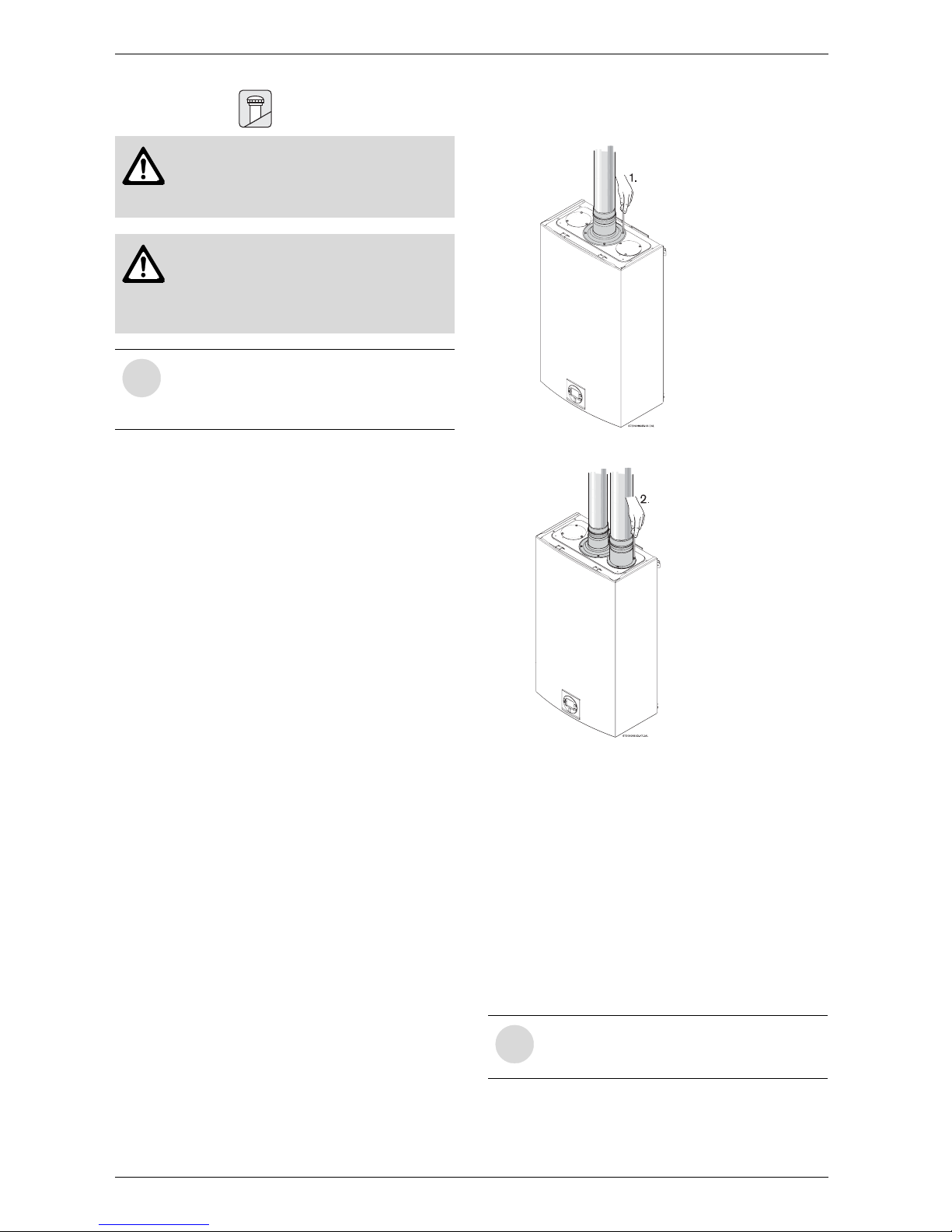
Attaching the exhaust and air inlet connection
adaptors to the top of the heater
Fig. 23 Exhaust connection
Fig. 24 Inlet connection
B Attach the flue gas exhaust accessory to the top of
the unit Fig. 23 (position 1) using the 4 screws and
gasket provided, and fully insert vent pipe into the
accessory. Take extra care that the blue gasket is
positioned properly.
B Attach the combustion air inlet accessory to the top
of the unit Fig. 24 (position 2) using the 3 screws and
gasket provided, and install 3" air intake pipe over the
accessory.
NOTE: The combustion air accessory can be
installed on the top right or on the top left side of the
heater. The combustion air inlet that is not used must
be kept sealed.
Warning: Do not reduce the vent
(exhaust and combustion) pipe sizes
and do not common vent with any other
vented appliance or stove.
Warning: Failure to vent the exhaust
gases to the outside (see Table 3 for
proper material) may result in
dangerous flue gases filling the
structure in which it is installed.
i
Observe the listed maximum lengths of
vent system, which vary depending on
type of termination used. The maximum
permissible lengths are listed in Table 9.
i
Ensure that exhaust vent pipe is fully
inserted in collar past the blue gasket for
a proper seal.
6 720 608 643
Installation instructions
17
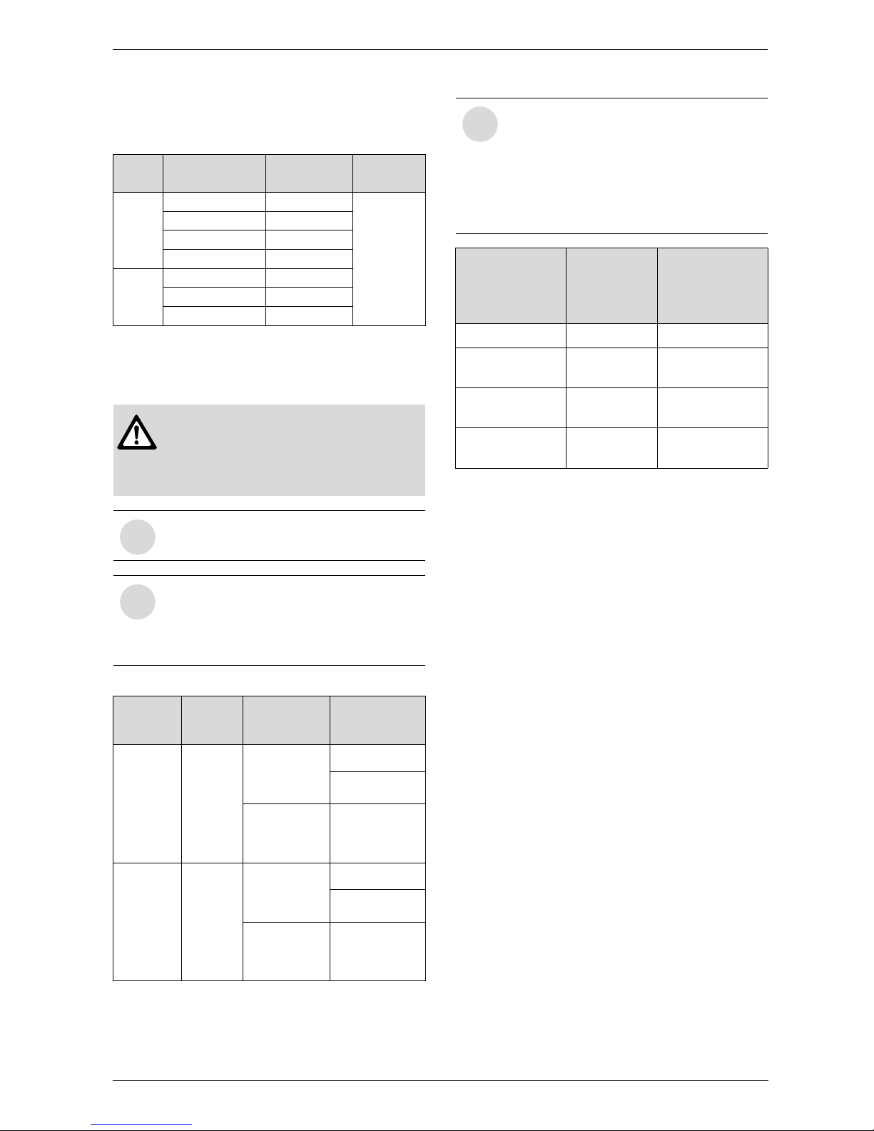
3.12.1 Vent material and specifications
All combustion air and vent pipe materials and fittings
must comply with the following:
For specific questions concerning vent material,
specifications, usage or installation, please
contact the vent manufacturer directly.
Maximum vent length
Item Material United States Canada
Vent or
air pipe
and
fitting
PVC schedule 40 ANSI/ASTM D1785
CSA or ULC
certified only
(ULC-S636)
PVC-DWV ANSI/ASTM D2665
CPVC schedule 40 ANSI/ASTM F441
ABS-DWV schedule 40 ANSI/ASTM D2661
Pipe
cement /
primer
PVC ANSI/ASTM D2564
CPVC ANSI/ASTM F493
ABS ANSI/ASTM D2235
Table 3 Approved vent material
Warning: Protect the exhaust and inlet
from leaves and debris by installing a
screen on the end of the terminator.
Failure to do so may result into
malfunction or damage to the appliance.
i
Do not use cellular foam core pipe.
i
Ensure that a condensate drain is always
installed at the condensate outlet on the
bottom of the appliance. See section
“3.12.3 Connecting the condensate water
drain” on page 23.
Single
pipe
Diam.
Max.
length
Allowed
terminals
Exhaust
vent
3 or 4
inches
26 feet +
1st elbow +
end terminal
“T” terminal
90° elbow
18 feet +
1st elbow +
end terminal
Concentric
(KGAVT0601CVT)
Intake
vent
3 or 4
inches
26 feet +
1st elbow +
end terminal
“T” terminal
90° elbow
18 feet +
1st elbow +
end terminal
Concentric
(KGAVT0601CVT)
Table 4 Maximum vent length (intake + exhaust)
i
Note:
B For twin pipe a maximum combination
length:
52 ft + two 90º elbows + two terminals.
B For concentric solution a maximum
combination length:
36 ft + two 90º elbows + two terminals.
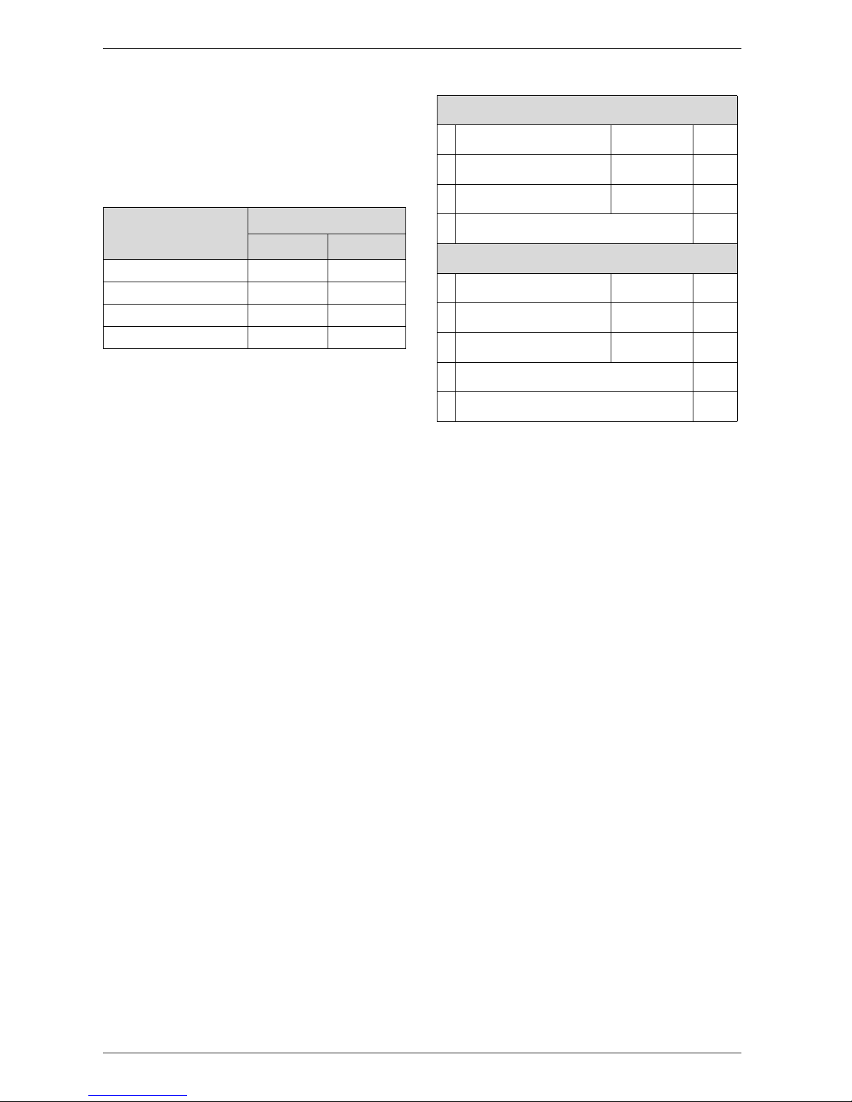
Description Part no.
Kit part no. and
quantity
KGAVT0601CVT
3- In. Rain Cap 320561-402 1
4- In. Diameter
SDR-26 Pipe
24 In. long 1
3- In. Y
Concentric Fitting
320656-402 1
2- ½ In. Diameter
SDR-26 Pipe
37-1/8 in. long 1
Table 5 Concentric vent part breakdown
6 720 608 643
18
Installation instructions
3.12.2 Vent length calculation
Adjusting the minimum power (P2) based on the
total combined vent length.
After installing the GWH C 800 ES, the minimum power
fan speed must be selected to compensate for variation
in vent pipe length.
Note: See table 4 for maximum vent lengths.
Total vent length calculation
B Determine the total length of all straight sections of
vent pipe and enter in table 7, line 1.
B Count the number of 90° elbows used, multiply by 5,
and enter that value in line 2. (Do not count end
terminal and first elbow after the appliance).
B Count the number of 45° elbows used, multiply by 3,
and enter that value in line 3.
B Repeat steps 1 through 3 for air intake pipe and enter
those values in the intake section of table 7.
B Add line 4 from Exhaust to line 4 of Intake and enter
result in line 5.
This is the total equivalent vent length.
NOTE: If total vent length calculated is 19 feet or
less, no P2 adjustment is needed.
Fittings or Piping Equivalent
feet m
45 degree elbow 3 0.91
90 degree elbow 5 1.52
plastic pipe per foot 1 0.30
concentric vent kit 3 0.91
Table 6 Friction Loss Equivalent in piping and fittings
Exhaust
1
Straight section length __ = ____
2
90° elbows (qty) __ x 5 = ____
3
45° elbows (qty) __ x 3 = ____
4 Total:
____
Intake
1
Straight section length __ x 1 = ____
2
90° elbows (qty) __ x 5 = ____
3
45° elbows (qty) __ x 3 = ____
4
Total: ____
5
Total equivalent vent length = ____
Table 7 Determining vent length combination (see
example in Table 8)
 Loading...