

Bosch GWH 250SXO, GWH 635 ES, GWH 2400E, GWH 2400EO, GWH 2400ES Control User Manual
...
Bosch Remote Control
For: GWH 635 ES/635 ESO/250SX/250SXO/2400E
/2400EO/2400ES/2700ES/715ES/C800ES/C920ES
/C920ESC/EVOLUTION 500/INTEGRA 500/C1210ES
/C1210ESC/C1050ES/940ES/940ESO/830ES
6720606990-00.1JS
6 720 606 990 (2010/05) US
6720606990-1005_(Remote control).fm Page 1 Thursday, July 1, 2010 11:46 AM
2
Contents
6 720 606 990
Contents
1 FCC Declaration of conformity 3
2 Remote control data 4
3 Remote control Kit 4
3.1 Parts supplied 4
4 Remote control installation for:
GWH 635 ES/GWH 635 ESO
/250SX/250SXO/2400E
/2400EO 5
4.1 Remote control transceiver PCB
installation 5
4.2 Remote control activation 7
4.2.1 AF board 7
4.2.2 SU board 8
5 Remote control installation for:
GWH C920 ES/GWH C920ESC
/GWH C800 ES/GWH 715 ES
/GWH 2700 ES/GWH2400ES
/EVOLUTION500/INTEGRA500
/C1210ES/C1210ESCC1050ES
/940ES/940ESO/830ES 10
5.1 Remote control transceiver PCB
installation 10
5.2 Remote control activation 11
6 Remote control 13
6.1 Description of the LCD 13
6.2 Hot water temperature adjustment
by remote control 13
6.3 "Program" button on the remote
control 13
6.4 "Priority" function 15
6.5 Error messages 16
7 Troubleshooting 16
7.1 Replacing batteries 16
7.2 Cleaning 16
7.3 Troubleshooting 16
8 Notes 19
6720606990-1005_(Remote control).fm Page 2 Thursday, July 1, 2010 11:46 AM

3
Safety instructions
6 720 606 990
Safety instructions
B Read the following instructions very
carefully to ensure correct
operation.
B Follow safety instructions.
1 FCC Declaration of
conformity
This device meets the requirements of
FCC Directives.
This device complies with Part 15 of
the FCC rules. Operation is subject to
the following two conditions: (1) This
device may not cause harmful
interference, and (2) this device must
accept any interference received,
including interference that may cause
undesired operation.
Caution: Any
changes or
modifications not
expressly approved by
the party responsible
for compliance could
void the user’s
authority to operate
the equipment.
Caution: the remote
control is water
resistant and can also
be used in the shower
. Nevertheless, it
is not waterproof and
must not be immersed
in water, for instance
in the bathtub .
Caution: The
remote control can
be used only in the
following countries:
United States of
America and
Canada.
6720606990-1005_(Remote control).fm Page 3 Thursday, July 1, 2010 11:46 AM
4
Remote control data
6 720 606 990
2 Remote control data
Remote control for temperature
adjustment of Bosch water heaters.
Technical Data:
Further Information:
3 Remote control Kit
3.1 Parts supplied
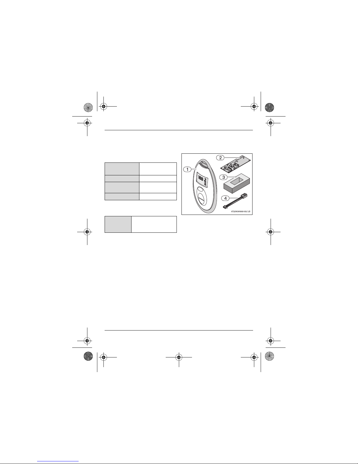
Fig. 1 Parts
1 Remote control
2 Remote control transceiver PCB
3 Support block (used only for GWH
635 ES/GWH 635 ESO/250SX/
250SXO)
4 PCB connection cable
Battery power
supply
Alkaline AA LR 6
2 x 1.5V
Frequency 903 MHz
Type of
protection
IP X6
User range
98 ft (30 m)
Remote
control
Up to 6 remote controls
can be programmed for
one single appliance.
6720606990-1005_(Remote control).fm Page 4 Thursday, July 1, 2010 11:46 AM
5
Remote control installation
6 720 606 990
4 Remote control installation for: GWH 635 ES/GWH
635 ESO/250SX/250SXO/2400E/2400EO
4.1 Remote control transceiver PCB installation
Pre-installation preparation
B Disconnect power supply to heater.
B Remove plastic decals on front
panel.
B Loosen two Philips head screws
located behind plastic decals.
B Lift front cover upward and remove.
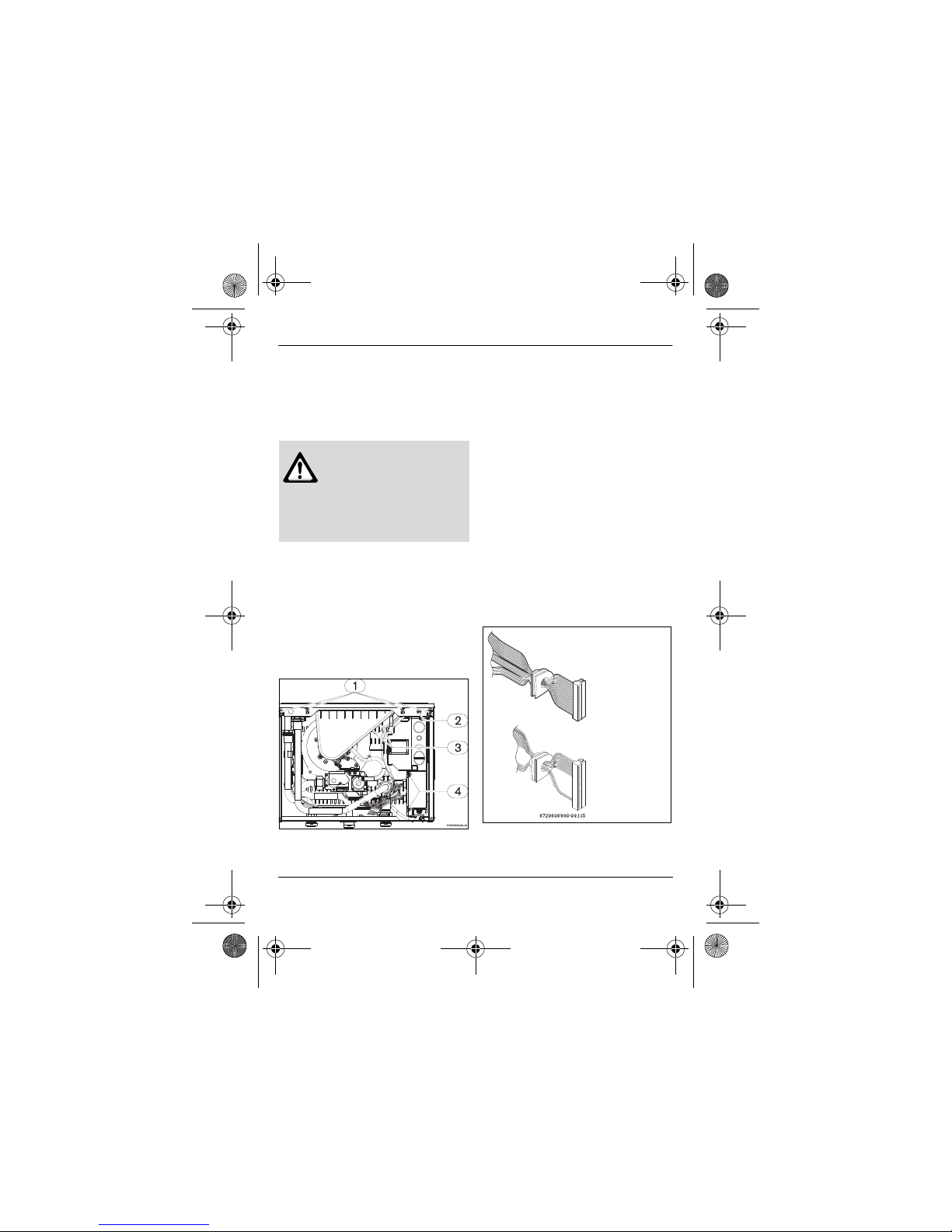
Fig. 2
B Remove the 5 screws on the front
retaining bar (see Fig. 2, pos. 1 and
2) being careful not to damage the
foam sealant material on it.
B Remove control unit auxiliary cover
(Fig. 2, pos. 4).
B Remove the two electrical strip
connectors inside the auxiliary cover
(Fig. see diagram below) and then
loosen the 110V power supply cord
retaining nut located underneath the
heater. Once loosened, the power
cord can be pulled up through the
heater to provide sufficient slack.
Electrical strip con nectors
B At the ignition electrodes, pull off the
2 yellow igniter wires that come from
Warning: For safety
reasons, disconnect
the power supply to
the water heater
before performing
installation.
Once auxiliary
cover is off, pull
off the two
electrical strip
connectors from
the board. Once
off, the wiring
harness can be
removed from the
case by pulling
their rubber seals
outward.
6720606990-1005_(Remote control).fm Page 5 Thursday, July 1, 2010 11:46 AM
6
Remote control installation
6 720 606 990
the top of the control unit (Fig. 2,
pos. 3). Then pull the complete
control unit forward and out of the
heater, pull up the power supply
cord further if more slack is needed.
B While holding the unit in one hand or
resting it on a flat surface, remove
the front cover of the control unit by
removing the 4 screws.
Remote control transceiver PCB
installation
B Open control unit top cover (Fig. 3,
pos. 1).
B Remove the protective paper (Fig. 3,
pos. 2) from one face of the support
and attach it to the main PCB as
shown in Fig. 4.
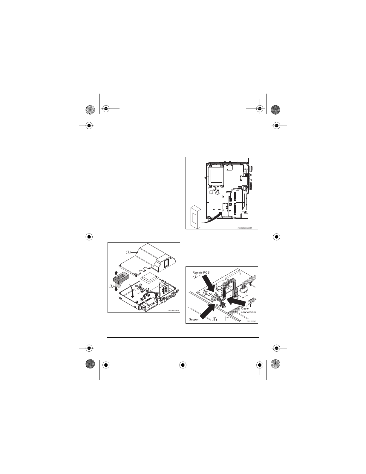
Fig. 3
B Remove the other protective paper
and attach the remote control PCB
as shown in Fig. 5.
Fig. 4 Support correct position
B Use the supplied cable to connect
between the main PCB and the
remote control PCB as shown in Fig.
5.
Fig. 5
6720606990-1005_(Remote control).fm Page 6 Thursday, July 1, 2010 11:46 AM
 Loading...