

Aspirating Smoke Detector
FCS‑320‑TP1 | FCS‑320‑TP2
en
Operation Guide


Aspirating Smoke Detector Table of contents | en 3
Bosch Sicherheitssysteme GmbH Operation Guide 2018.04 | 2.0 | F.01U.130.926
Table of contents
1
Safety 6
2
General 7
2.1 Introduction 7
2.2 Warranty 7
2.3 Copyright 7
2.4 Disposal 7
3
Technical Specifications 8
3.1 Product Description 8
3.2 Areas of application 9
3.3 System Overview 12
3.4 Functions 12
3.5 FCS-320 Series Aspirating Smoke Detectors and Accessories 14
3.5.1 Overview 14
3.5.2 FCS-320 series connections 15
3.5.3 FCS-320-TP1/FCS-320-TP2 displays 16
3.5.4 FCS-320-TT1/FCS-320-TT2 displays 17
3.5.5 FAS-ASD-DIAG Diagnostic Software 18
3.5.6 Remote indictors 18
3.5.7 Device mounting 19
3.5.8 Measures for Reducing Operating Noise 19
3.6 Pipe system components 20
3.6.1 Overview 20
3.6.2 Air sampling openings 21
3.6.3 Ceiling Lead-through Adapter 22
3.6.4 Air-Return Pipe for Pressure Areas and Atmospheric Loads 23
3.6.5 Air filters for dusty areas 24
3.6.6 Water Separator for Humid Areas 24
3.6.7 Detonation Safety Barrier for Potentially Explosive Areas 25
3.7 Scope of Delivery: Smoke Aspiration System 26
3.8 Technical data 28
3.8.1 FCS-320 Series Aspirating Smoke Detectors 28
3.8.2 Pipe System 29
3.8.3 Smoke Aspiration System Components 29
4
Planning 32
4.1 Regulations 32
4.2 Principles of Pipe Planning 33
4.3 Airflow monitoring 36
4.4 Defining the Response Sensitivity 37
4.5 Planning Limits 38
4.6 Standard Pipe Planning 39
4.6.1 Determining the Necessary Accessories 39
4.6.2 Pipe Planning with Pipe Accessories 39
4.7 Pipe Planning for Single-Hole Monitoring 49
4.8 Simplified Pipe Planning 55
4.9 Planning for Long Pipe Feed Lines 58
4.10 Planning with Acceleration Openings 59
4.11 Planning for Forced Airflow 69
4.12 Project planning with branch pipes 72

4 en | Table of contents Aspirating Smoke Detector
2018.04 | 2.0 | F.01U.130.926 Operation Guide Bosch Sicherheitssysteme GmbH
4.13 Planning with air sampling hose 74
4.14 Planning with air return 75
4.15 Power Supply 76
5
Installing the Aspirating Smoke Detector 78
5.1 General 78
5.2 Installing the Detector Module 78
5.3 Settings on the Unit Motherboard 79
5.3.1 Setting the Fan Voltage 79
5.3.2 Number of Detector Modules 80
5.4 Installing the Unit 80
5.5 Installing the Reset Board 83
5.5.1 Installing the reset board 83
5.5.2 Installing the reset board 84
5.5.3 Electrical connection of the reset board 85
5.6 Connection to the Fire Panel 85
5.6.1 Electrical Connection 85
5.6.2 FCS-320-TP1 / FCS-320-TT1 Connection to the Fire Panel 87
5.6.3 FCS-320-TP2 / FCS-320-TT2 Connection to the Fire Panel 87
5.7 DIP switch settings 87
5.8 Connecting an External Detector Alarm Display 89
5.9 Data Logging 89
5.10 Replacing a Detector Module 89
6
Installation of the Pipe System 91
6.1 Length Change of the Pipe System 92
6.2 Air Sampling Openings 93
6.3 Ceiling Lead-through 95
6.4 Monitoring with Forced Airflow 95
6.4.1 Detection at Intake and Exhaust Openings 95
6.4.2 Detection in the Bypass 96
6.5 Air Filter 97
6.5.1 Installing the Air Filter Box 97
6.5.2 Filter Change on the Air Filter Box 97
6.6 Air-return Pipe 98
6.7 Three-way Tap 99
6.8 FAS‑ASD‑WS Water Separator 100
6.9 Detonation Safety Barrier 101
6.10 Test Adapter 101
7
Commissioning 103
7.1 Preparation 103
7.2 Calibrating the Airflow Sensor 104
7.2.1 Air-Pressure-Independent Calibration 104
7.2.2 Air-Pressure-Dependent Calibration 105
7.3 Testing the Detector Module and Alarm Transfer 105
7.4 Checking Malfunction Transmission 106
7.5 Checking Airflow Monitoring 106
7.6 FCS-320 Functional Test 107
7.6.1 Preparations for the Functional Test 107
7.6.2 Conducting the Functional Test 108
8
Maintenance 110

Aspirating Smoke Detector Table of contents | en 5
Bosch Sicherheitssysteme GmbH Operation Guide 2018.04 | 2.0 | F.01U.130.926
8.1 Visual check 110
8.2 Flash Code Table 110
8.2.1 1 Flash - Error: Internal Voltage Monitoring 1 110
8.2.2 2 Flashes - Error: Internal Voltage Monitoring 2 111
8.2.3 3 Flashes - Error: Fan Voltage Monitoring 111
8.2.4 4 Flashes - Error: Air Pressure Correction Voltage Monitoring 112
8.2.5 5 Flashes - Error: Programming Error 113
8.2.6 6 Flashes or 7 Flashes - Error: Internal Error 1 or Internal Error 2 113
8.2.7 8 Flashes: Unit Initialization 113
8.3 Detector Module and Alarm Transmission 113
8.4 Pipe system 114
8.5 Checking the Airflow Sensor Calibration 114
8.6 Airflow Monitoring 116
8.7 Malfunction Transmission 116
8.8 Maintenance Intervals 116
9
Appendix 118
9.1 Air Pressure Correction Tables for Airflow Sensor Calibration 118
9.1.1 Equipment protection 118
9.1.2 Space Protection (I-pipe System) 119
9.1.3 Space Protection (U, Double U, and H-pipe System) 121
9.2 Planning without filter 123
9.2.1 Without any other pipe accessories 123
9.2.2 With water separator 124
9.2.3 With detonation safety barrier 124
9.3 Planning with air filter 125
9.3.1 Without any other pipe accessories 126
9.3.2 With water separator 126
9.3.3 With detonation safety barrier 127
9.4 Test Log FCS-320 Series Aspirating Smoke Detectors 127
Index 130
6 en | Safety Aspirating Smoke Detector
2018.04 | 2.0 | F.01U.130.926 Operation Guide Bosch Sicherheitssysteme GmbH
1 Safety
The following symbols identify points in this operation guide that require particular attention
in order to guarantee smooth operation and prevent damage.
Notice!
Operational malfunction can be prevented and operational improvements can be achieved by
observing these instructions.
!
Caution!
This symbol warns against actions and behavior which, if disregarded, could cause property
damage.
!
Warning!
This symbol warns against actions and behavior which, if disregarded, could cause personal
injury.

Aspirating Smoke Detector General | en 7
Bosch Sicherheitssysteme GmbH Operation Guide 2018.04 | 2.0 | F.01U.130.926
2 General
2.1 Introduction
This operation guide describes the smoke aspiration systems featuring FCS-320 series
aspirating smoke detectors and the associated aspiration pipe system.
The FCS-320 designation in this operation guide refers to all FCS-320 versions (FCS-320‑TP1,
FCS-320‑TP2, FCS-320‑TT1 und FCS-320‑TT2). Specific references are made to differences
between the individual versions.
The "FAS/FCS" designation in the illustrations and graphics also refers to all models in the
FCS-320 series (FCS‑320‑TP1, FCS‑320‑TP2, FCS‑320‑TT1, FCS‑320‑TT2), and also applies to
LSN models of aspirating smoke detectors.
This operation guide describes the smoke aspiration systems featuring FCS-320 series
Aspirating Smoke Detectors and the associated aspiration pipe system.
The FCS-320 designation in this operation guide refers to all FCS-320 series versions. Specific
references are made to differences between the individual versions.
2.2 Warranty
The operation guide is subject to technical modification without prior notice and makes no
claim to completeness. Our "delivery and installation conditions" apply as a matter of
principle. Warranty and liability claims in case of personal injury and property damage cannot
be asserted if they are based on one or more of the following causes:
– Insufficient attention to the instructions with respect to planning, installation of the
aspirating smoke detector, installation of the pipe system, commissioning and
maintenance
– Use of the smoke aspiration system contrary to the regulations
– Insufficient monitoring of wearing parts
– Faulty repairs
– Arbitrary constructional changes to the smoke aspiration system
– Acts of God.
Bosch Sicherheitssysteme GmbH, hereinafter referred to as Bosch, assumes no liability for
damage or malfunction arising through failure to comply with this operation guide.
!
Caution!
The equipment may only be installed by authorized and qualified personnel!
2.3 Copyright
The copyright to this operation guide remains with Bosch.
This operation guide is intended exclusively for installation engineers and their employees.
Reprinting this operation guide or extracts thereof is permitted for internal purposes only.
2.4 Disposal
Unusable electrical and electronic devices or modules must not be disposed of with normal
household refuse. They must be disposed of in compliance with the applicable regulations
and directives (e.g. WEEE in Europe).

8 en | Technical Specifications Aspirating Smoke Detector
2018.04 | 2.0 | F.01U.130.926 Operation Guide Bosch Sicherheitssysteme GmbH
3 Technical Specifications
3.1 Product Description
Aspirating smoke detectors from the FCS-320 series are active fire detection devices that are
connected directly to conventional lines for early smoke and fire detection. They are used for
room and equipment protection as well as for monitoring air-conditioning units or ducts.
Variants
The FCS-320‑TP1 and FCS-320‑TP2 models feature LED displays indicating operating mode,
malfunction and alarm (the FCS-320‑TP2 has two alarm displays). The FCS-320‑TT1 and
FCS-320‑TT2 models offer differentiated alarm displays (info, pre and main alarm) as well as a
10-level smoke display (on the FCS-320‑TT2, all alarm and smoke level displays are doubled).
The FCS-320‑TP1 and FCS-320‑TT1 variants are each fitted with a detector module.
Both FCS-320‑TP2 and FCS-320‑TT2 have two integrated detector modules each. Two
aspiration pipes can be connected, enabling two areas to be monitored. This effectively
doubles the monitoring area.
Dual-detector dependency
The use of two detector modules in variants FCS-320-TP2 and FCS-320-TT2 also enables a
dual-detector dependency to be realized. This means that one area can be monitored by two
pipe systems.
Two alarm stages
Alternatively, the FCS-320-TP2 and FCS-320-TT2 can have two alarm stages configured. A pipe
system is connected via a pipe adapter on two detector modules. Selecting different response
sensitivities for the detector modules enables the time-staggered triggering of two main
alarms.
Sensitivity
Three detector module versions are available for the FCS-320 aspirating smoke detector
series:
– DM‑TP‑50(80) with a response sensitivity of up to 0.5%/m (0.8%/m) light obscuration
– DM‑TP‑10(25) with a response sensitivity of up to 0.1%/m (0.25%/m) light obscuration
– DM‑TP‑01(05) with a response sensitivity of up to 0.015%/m (0.05%/m) light obscuration.
Depending on the detector module used, the FCS-320‑TT1 and FCS-320‑TT2 models can
achieve a resolution ten times higher for displaying up to 0.05%/m (0.08%/m), 0.01%/m
(0.025%/m) or 0.0015%/m (0.005%/m) light obscuration.
Notice!
The sensitivity value is based on measurements with standard test fires (old value in
brackets).
The new High-Power-Light-Source technology permits a broad detection spectrum over all
standardized fires.
LOGIC×SENS
The intelligent signal processing LOGIC·SENS distinguishes between deception variables and
fire events in order to prevent false alarms.
Reliable airflow monitoring
Analogous to point-type smoke detectors, which are monitored electronically for wire breaks
and short-circuits, highly sensitive and dependable airflow monitoring is required for smoke
aspiration systems. The airflow sensors used in the FCS-320 series reliably detect
malfunctions such as pipe breakage or obstructions in the air sampling openings.
Airflow monitoring is temperature-compensated and can be set depending on the air pressure.

Aspirating Smoke Detector Technical Specifications | en 9
Bosch Sicherheitssysteme GmbH Operation Guide 2018.04 | 2.0 | F.01U.130.926
The small airflow unit also contains a dynamic airflow sensor that enables a response to small
and fast changes in the airflow.
Patented air sampling openings
The air sampling openings of the pipe system require clearly defined bore diameters that
depend on the planning and design. These precise air sampling openings are created using
patented aspiration reducing film sheets, marking tape, and clips, which not only permit easy
installation, but also prevent "whistling" noises. Another advantage is the quick and easy
detection and checking of the air sampling opening diameters.
Point-type detector projection
The system’s aspiration points can be equated with point-type smoke detectors. The
monitoring areas can therefore be planned in accordance with the applicable national
regulations.
Diagnostics
There is a system available with the FAS-ASD-DIAGdiagnostic software that enables quick and
convenient error containment for maintenance and service. The current and stored unit status
is read out via cable data transmission to the PC.
Selecting the fan voltage
The fan voltage for special planning can be increased from 6.9V to 9V by relocating the fan
jumper. This increases the air transport speed and therefore reduces detection time.
3.2 Areas of application
Thanks to their detection principle, FCS-320 aspirating smoke detectors represent an
extremely versatile fire protection solution.
Principle
Air samples are taken from the monitoring range by a pipe system with defined aspiration
borings and then fed to the detection module.
This is especially well-suited for areas in which point-type detectors cannot be used or can
only be used under certain circumstances. These include:
– Areas that are difficult to access, in which point detectors are difficult to install and
maintain
– Air-conditioned areas
– Areas that require the earliest detection possible
– Areas with a height greater than that allowed for point detectors
– Areas in which point detectors are not desired for aesthetic reasons
– Areas in which strong electromagnetic fields occur
– Areas that are exposed to high or low temperatures
– Areas with contaminated air that require filter elements
– Areas that must be protected against vandalism.
Space protection
The FCS-320 series is suitable for monitoring areas such as
– Those with double floors, false ceilings
– Tunnels, ducts, barely accessible hollow spaces
– Storage, high-rise warehouses, elevator shafts
– Museums, cultural institutions
– Hotel rooms, hospital rooms, offices, prison cells, train compartments
– Freezer storage
10 en | Technical Specifications Aspirating Smoke Detector
2018.04 | 2.0 | F.01U.130.926 Operation Guide Bosch Sicherheitssysteme GmbH
FAS / FCS
1
2
TITANUS MICRO·SENS ®
E
D
C
B
A
10
9
8
7
6
5
4
3
2
1
TITANUS MICRO·SENS ®
E
D
C
B
A
10
9
8
7
6
5
4
3
2
1
Principle of area monitoring with FCS-320 series Aspirating
Smoke Detectors
1 Room pipe system
2 Double-floor pipe system
Area monitoring with air-conditioning
Area monitoring occurs
– In rooms with air-conditioning for server rooms etc.
– In ventilation ducts
– In double floors, false ceilings
– In IT rooms, e-distributor rooms, transformer cells
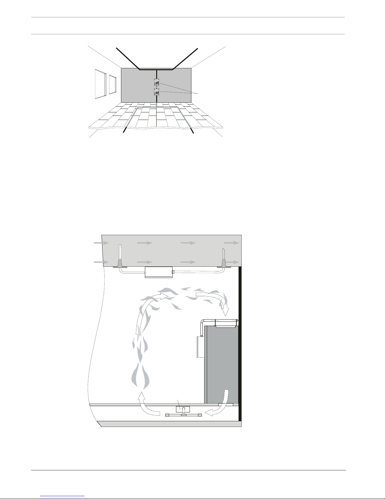
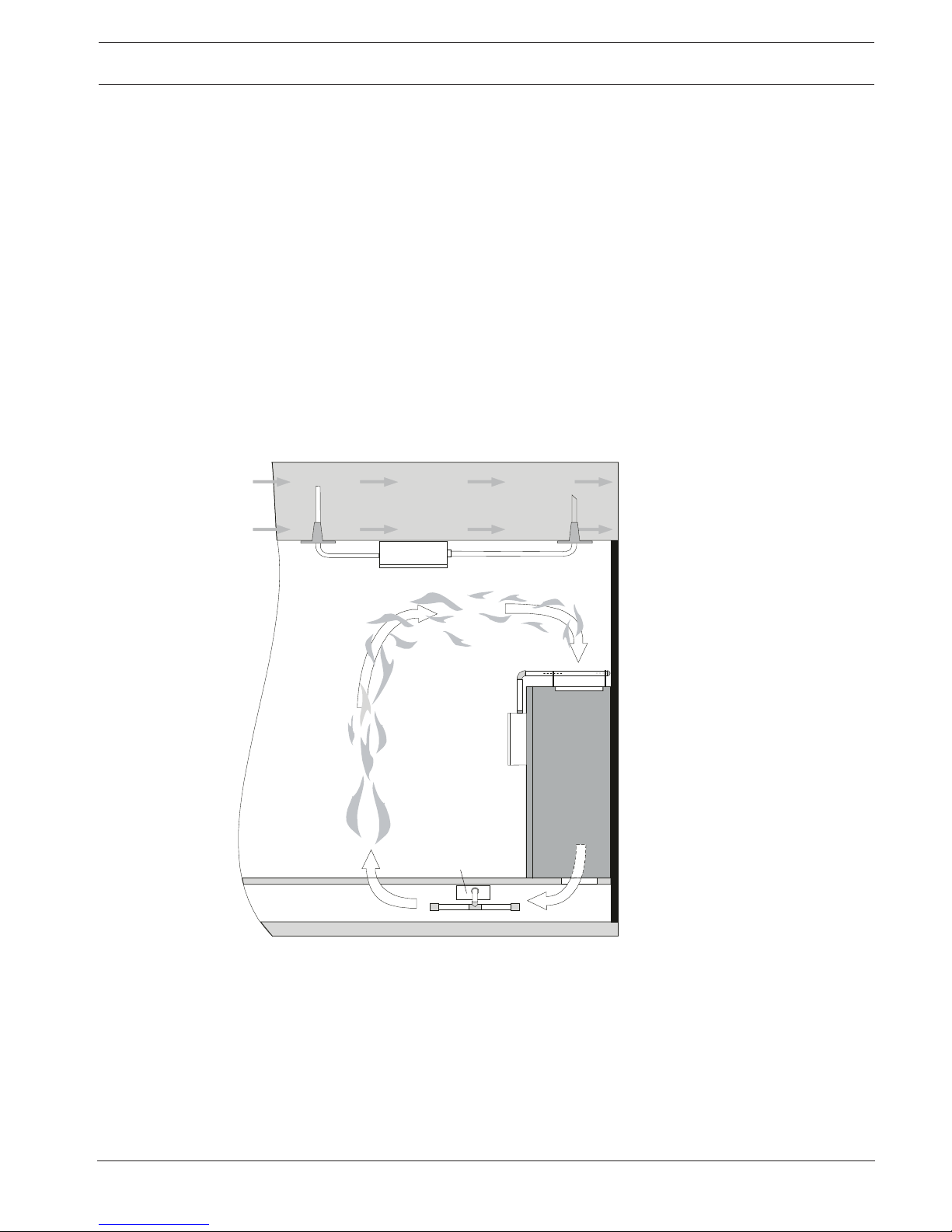
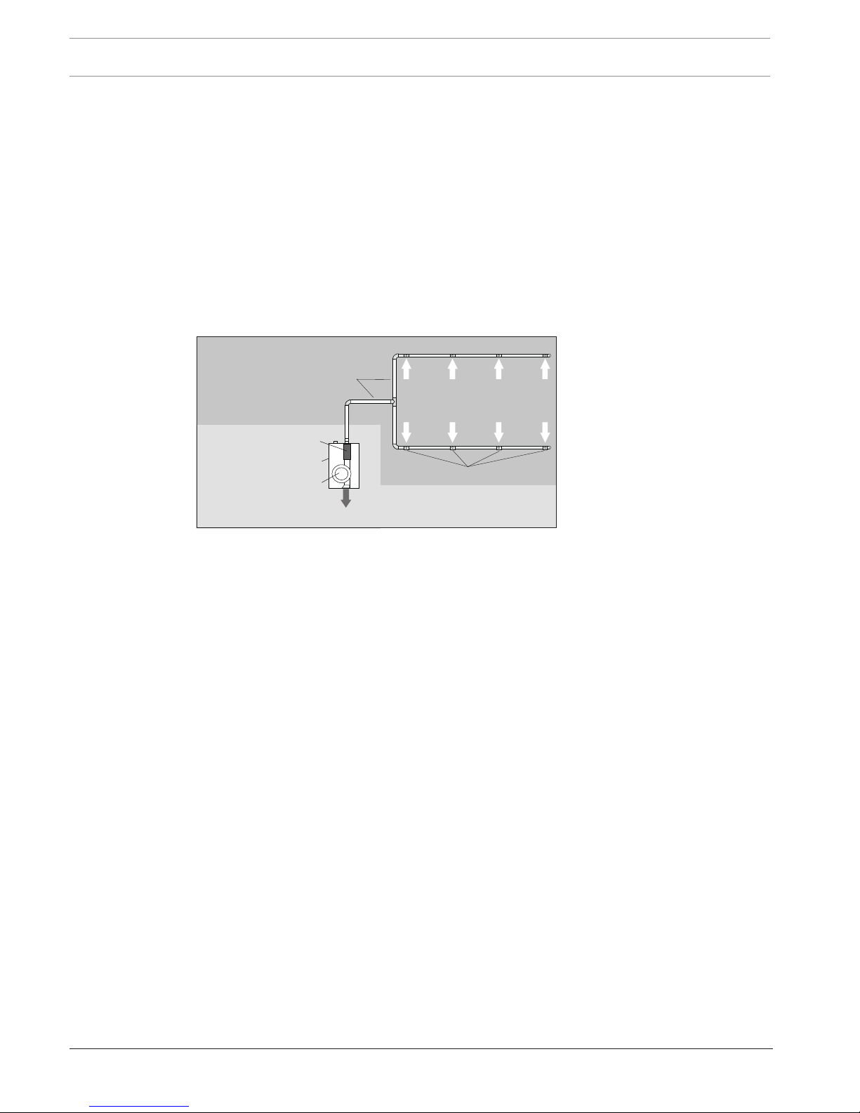
– On air-conditioning units (see figure below) or
– In the bypass in air-conditioning ducts.
FAS / FCS
FAS / FCS
FAS / FCS
1
2
Monitoring options for an air-conditioning unit or an airconditioning duct (depiction of principle)
1 Air-conditioning duct
2 Air-conditioning unit
The FCS-320 Aspirating Smoke Detector can be used for early fire detection in areas with
special-purpose air conditioning.
Aspirating Smoke Detector Technical Specifications | en 11
Bosch Sicherheitssysteme GmbH Operation Guide 2018.04 | 2.0 | F.01U.130.926
Thanks to its high sensitivity, expensive goods and equipment can be monitored reliably. The
aspirating smoke detectors from the FCS-320 series are therefore especially suitable for areas
of application:
– Where early intervention is essential due to a high value concentration
– Where equipment must always be operational
– Where highly sensitive detection is necessary (e.g. in areas where, due to built-in filter
elements, the air contains a low concentration of smoke particles)
– Where high air-exchange rates prevail.
Area monitoring with air-conditioning
Area monitoring occurs
– In rooms with air-conditioning for server rooms etc.
– In ventilation ducts
– In double floors, false ceilings
– In IT rooms, e-distributor rooms, transformer cells
– On air-conditioning units (see figure below) or
– In the bypass in air-conditioning ducts.
FAS / FCS
FAS / FCS
FAS / FCS
1
2
Monitoring options for an air-conditioning unit or an airconditioning duct (depiction of principle)
1 Air-conditioning duct
2 Air-conditioning unit
The FCS-320 Aspirating Smoke Detector can be used for early fire detection in areas with
special-purpose air conditioning.
Thanks to its high sensitivity, expensive goods and equipment can be monitored reliably. The
aspirating smoke detectors from the FCS-320 series are therefore especially suitable for areas
of application:
– Where early intervention is essential due to a high value concentration
– Where equipment must always be operational
12 en | Technical Specifications Aspirating Smoke Detector
2018.04 | 2.0 | F.01U.130.926 Operation Guide Bosch Sicherheitssysteme GmbH
– Where highly sensitive detection is necessary (e.g. in areas where, due to built-in filter
elements, the air contains a low concentration of smoke particles)
– Where high air-exchange rates prevail.
3.3 System Overview
The smoke aspiration systems comprise an aspirating detector and pipe system.
The aspirating smoke detector comprises the detector module for detecting the smoke
aerosols, the aspiration unit for transporting the air samples to the detector module and the
airflow sensor for monitoring the pipe system for breakage and obstructions.
The pipe system comprises essentially pipe and fittings. The standard pipe system is made
from PVC or ABS. The pipes used for equipment monitoring should be halogen-free.
Each air sampling opening in the pipe system represents a point detector in the planning.
2
7
6
5
3
1
A
4
Overview of the aspirating smoke detector
A Pipe system
FCS-320 Aspirating smoke
detector
1 Smoke aspiration pipe
2 Air intake
3 Air sampling openings
4 Detector module
including airflow
monitoring
5 Housing
6 Aspiration unit
7 Air outlet
To guarantee reliable operation even under the most difficult conditions (clean rooms,
recycling area), there are numerous accessories available, such as air filters, water separators
and detonation safety barriers.
3.4 Functions
Air samples are taken from the area to be monitored via the aspiration unit. They are fed via a
pipe system with defined air sampling openings to the sensitive detection module.
Detector module
Depending on the response sensitivity of the detector module in use and programmed alarm
threshold, the FCS-320 series aspirating smoke detector triggers the alarm when the
corresponding light obscuration threshold is reached. With the FCS-320‑TP1 and the
FCS-320‑TP2, the alarm is displayed via the alarm LED and/or two alarm LEDs on the unit and
transmitted to a connected fire panel. The FCS-320‑TT1 and FCS-320‑TT2 versions offer
differentiated LED displays for info, pre and main alarm. Pre and main alarms are transmitted
to the fire panel (with FPA‑5000 Rel 2.1; additionally with info alarm from Rel 2.5 or above).
Various delay times can be programmed for the alarm thresholds, as well as for displaying and
transferring malfunctions. Alarm messages are saved and are reset after the cause has been
eliminated.
LOGIC·SENS
Aspirating Smoke Detector Technical Specifications | en 13
Bosch Sicherheitssysteme GmbH Operation Guide 2018.04 | 2.0 | F.01U.130.926
The LOGIC·SENS intelligent signal processing compares the measured smoke level with
known disturbance variables and decides between alarm and deception.
Detector module monitoring
Each detector module is monitored for contamination, signal malfunction and removal. Soiling
of the detector module has no effect on its sensitivity. With all variants, any malfunction is
displayed via the malfunction LED and transferred to the fire panel. Malfunctions caused by
brief environmental fluctuations can be eliminated with a time-delayed setting.
Airflow Monitoring
An airflow sensor checks the connected pipe system for breakage and obstruction.
The airflow sensor can – depending on the configuration of the pipe system – detect at least a
50% obstruction to a complete obstruction of the air sampling openings and a breakage in the
pipe system that results in a 50% loss from the air sampling openings. Should the fan fail, the
airflow in the pipe system is interrupted and this causes a blockage message. Airflow
monitoring is temperature-compensated and can be set depending on the air pressure.
On expiry of a defined delay, the malfunction is displayed on the aspirating smoke detector
and the message is transmitted to the fire panel. The monitoring window thresholds can be
modified to suit the environmental conditions (see Airflow Monitoring).
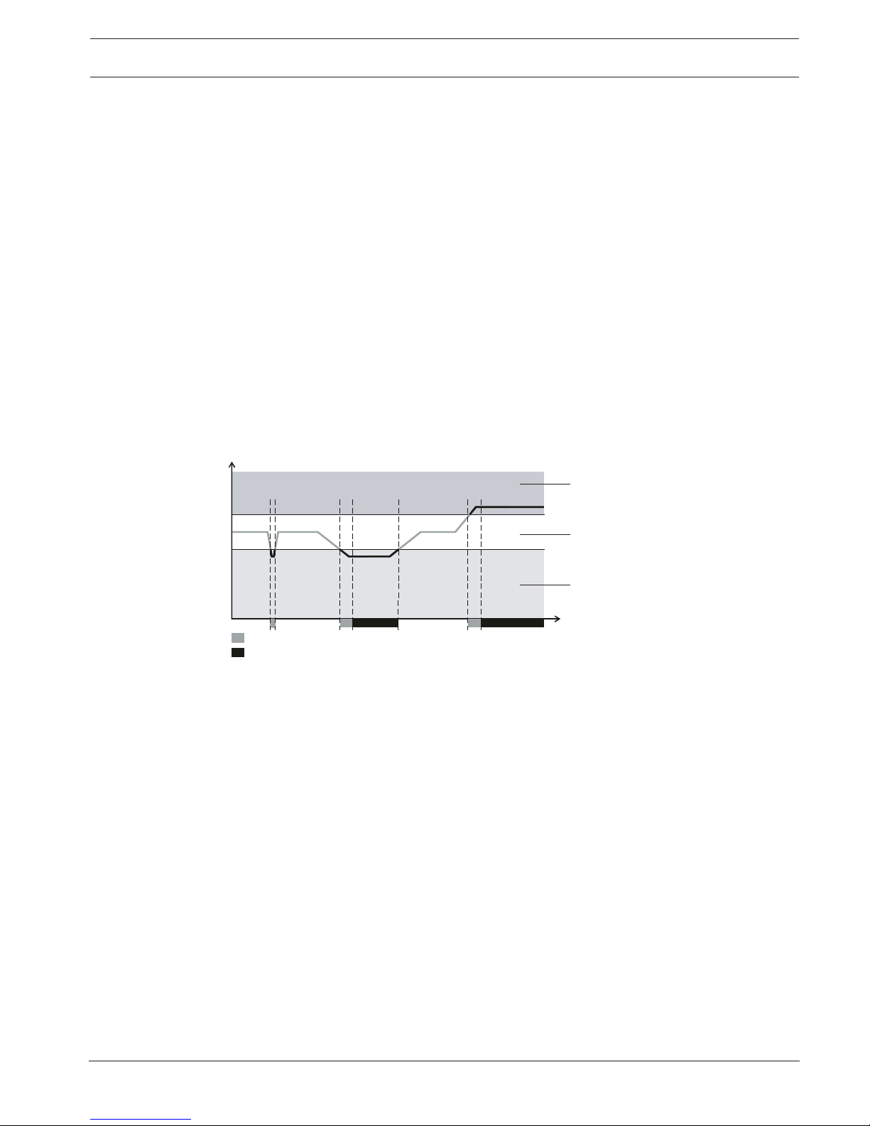
The principal signal curve of the airflow sensor is indicated in Airflow Monitoring.
S
t
4
7
8
6
1
2
5
3
Example of the signal process of the Airflow sensor in case of
malfunctions
S Airflow sensor signal
t Time
1 Normal airflow
2 Airflow too weak
3 Airflow too strong
4 Breakage
5 Obstruction
6 Monitoring window
7 Delay
8 Malfunction message
Fault Indication
An imminent detector module or airflow malfunction generates a malfunction message that is
displayed on the FCS-320.
Flash code for malfunction detection
Malfunctions and certain device statues are displayed using various LED flash codes on the
detector module's electronics PCB. Thus it is possible to differentiate quickly among
malfunctions that can be caused by a defective detector module, an obstruction, or a break in
the pipe system.
Resetting via fire panel
A malfunction message is reset via the connected fire panel. The panel resets alarm and
malfunction messages on the unit while simultaneously resetting the detector line via the
reset board.
Calibrating the airflow sensor
Automatic airflow sensor calibration makes it significantly easier to start the FCS-320. The
initialization phase is carried out according to or independently of the air pressure as desired.
14 en | Technical Specifications Aspirating Smoke Detector
2018.04 | 2.0 | F.01U.130.926 Operation Guide Bosch Sicherheitssysteme GmbH
To set the FCS-320 to the airflow typical for the pipe network, an airflow initialization (flowinit) procedure is carried out. This must be done for each unit once at the start after
installation, each time the pipe system is replanned/redesigned and after changing the fan
voltage. This enables the unit to determine and save the airflow typical for the pipe network.
Pipe System
A pipe system with an overall length of up to 300m can be connected to FCS-320 series
aspirating smoke detectors over a maximum of 32 aspiration points. Two pipe systems can be
connected to both the FCS-320‑TP2 and FCS-320‑TT2 variants. The entire pipe system then
has a total length of 2 x 280m and a maximum number of 2 x 32 aspiration points.
3.5 FCS-320 Series Aspirating Smoke Detectors and Accessories
3.5.1 Overview
2
A
3
C
E
G
F
1
B
D
FAS / FCS
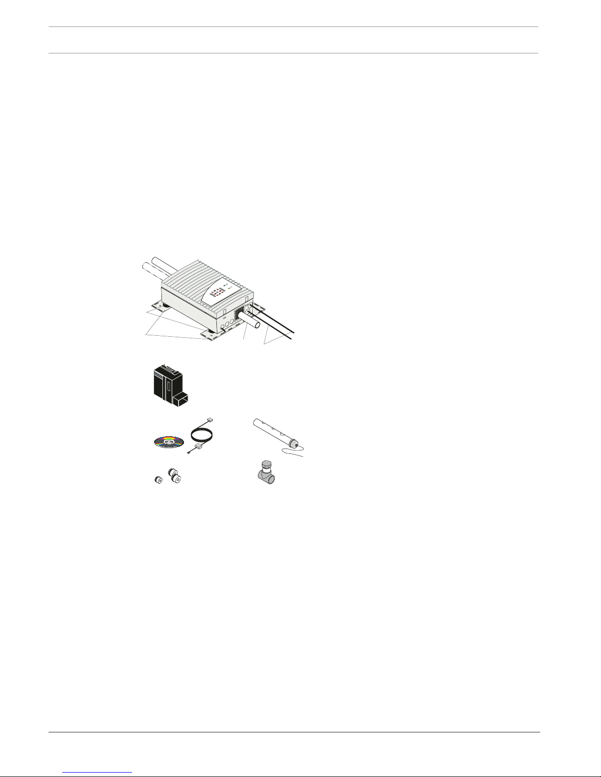
Overview of FCS-320 series aspirating
smoke detectors and accessories
1 Pipe system(s)
2 Connections to fire panel/power supply
3 Air-return pipe
A Vibration absorber (sold separately)
B MT-1 unit mounting
C Detector module
D DIAG Diagnostic Software with connection
cable
E Cable bushings (1xM20, 2xM25)
F Test pipe
G Test adapter
FCS-320 series aspirating smoke detectors comprise the following components:
– Plastic housing
– Plastic connection pieces
– Integrated air-return pipe
– Connection for pipe with 25mm external diameter
– Aspiration unit with optimized air supply
– Motherboard with interface for diagnostics system, LSN connections, connection for
shield wire, as well as DIP switch for address setting
– Supplementary package with cable bushings (1xM20, 2xM25)
– FCS-320-TP1 /FCS-320-TP2: optical displays for alarm, malfunction and operation
– FCS-320-TT1 /FCS-320-TT2: smoke level display(s), optical displays for info, pre and main
alarm, malfunction and operation
– 1 detector module (for FCS-320-TP1 and FCS-320-TT1) and/or 2 detector modules (for
FCS-320-TP2 and FCS-320-TT2).
Aspirating Smoke Detector Technical Specifications | en 15
Bosch Sicherheitssysteme GmbH Operation Guide 2018.04 | 2.0 | F.01U.130.926
Notice!
Only DM-TP-50(80), DM‑TP‑10(25) and DM-TP-01(05) detector modules certified to VdS may
be used in the FCS-320 series. The detector modules must be ordered separately.
See also
– FAS-ASD-DIAG Diagnostic Software, page 18
– Remote indictors, page 18
– Device mounting, page 19
– Ceiling Lead-through Adapter, page 22
– Water Separator for Humid Areas, page 24
– Detonation Safety Barrier for Potentially Explosive Areas, page 25
3.5.2 FCS-320 series connections
1
2
3
1
4
5
FAS-420 series
FAS-420 series
FAS / FCS
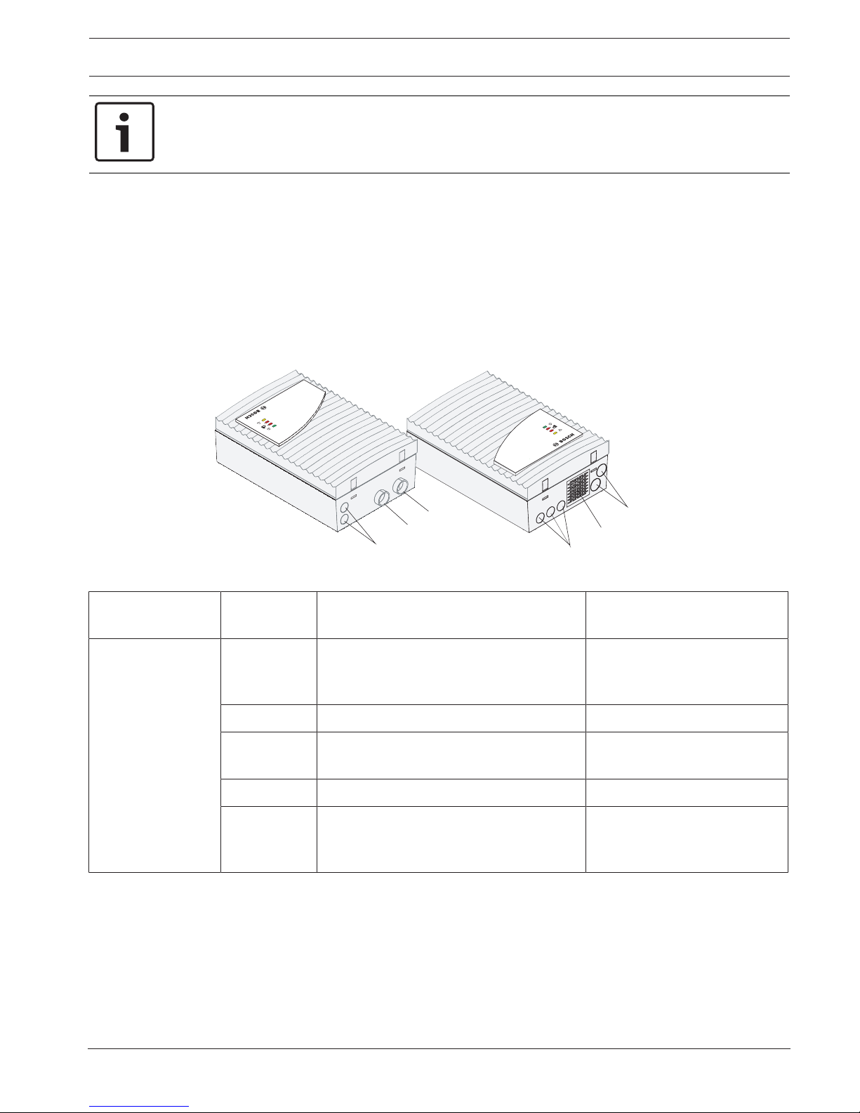
Figure3.1: FCS-320 connections (see table on next page for explanations)
Position in
figure
Function Explanation
FCS-320 series 1 Cable bushing for connection of fire panel
and additional power supply (input/
output)
1 x M20, for cable diameters of
8-12mm
2 Pipe system 1 connection For Ø 25mm pipe system
3 Pipe system 2 connection
(for FCS-320-TP2 and FCS-320-TT2 only)
For Ø 25mm pipe system
4 Connection for air-return pipe
5 Cable bushing for connection of fire panel
and additional power supply (input/
output)
2 x M25 for cable diameters of
9-14mm (expandable to 1418mm)
16 en | Technical Specifications Aspirating Smoke Detector
2018.04 | 2.0 | F.01U.130.926 Operation Guide Bosch Sicherheitssysteme GmbH
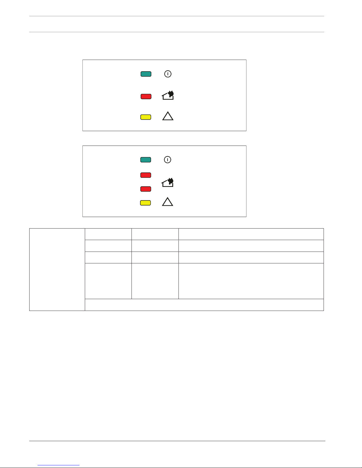
3.5.3 FCS-320-TP1/FCS-320-TP2 displays
FAS-420-TP1 / FCS-320-TP1
FAS-420-TP2 / FCS-320-TP2
1
2
Figure3.2: FAS‑420‑TP1/TP2, FCS‑320‑TP1/TP2 displays
FCS-320-TP Display LED Explanation
Operation Green Operation display
Alarm
1
Red Alarm indication
Fault Yellow Fault
– in the pipe system
– of a detector module
– caused by fan failure
1
Two alarm displays on the FCS-320-TP2
Aspirating Smoke Detector Technical Specifications | en 17
Bosch Sicherheitssysteme GmbH Operation Guide 2018.04 | 2.0 | F.01U.130.926
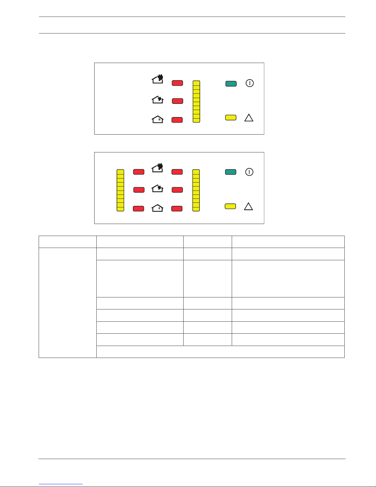
3.5.4 FCS-320-TT1/FCS-320-TT2 displays
i
1
2
3
4
5
6
7
8
9
10
FAS-420-TT1 / FCS-320-TT1
FAS-420-TT2 / FCS-320-TT2
i
1
2
3
4
5
6
7
8
9
10
1
2
3
4
5
6
7
8
9
10
12
Figure3.3: FAS‑420‑TT1/TT2, FCS-320-TT1/TT2 displays
FCS-320‑TT Display LED
1
Explanation
Operation Green Operation display
Fault Yellow Fault
– in the pipe system
– of a detector module
– caused by fan failure
Main alarm Red 100% smoke level
Pre-alarm
1
Red 66% smoke level
Info alarm
1
Red 33% smoke level
Smoke level display 1 to 10
1
10 yellow LEDs Current smoke level
1
All displays doubled on the FCS-320-TT2
18 en | Technical Specifications Aspirating Smoke Detector
2018.04 | 2.0 | F.01U.130.926 Operation Guide Bosch Sicherheitssysteme GmbH
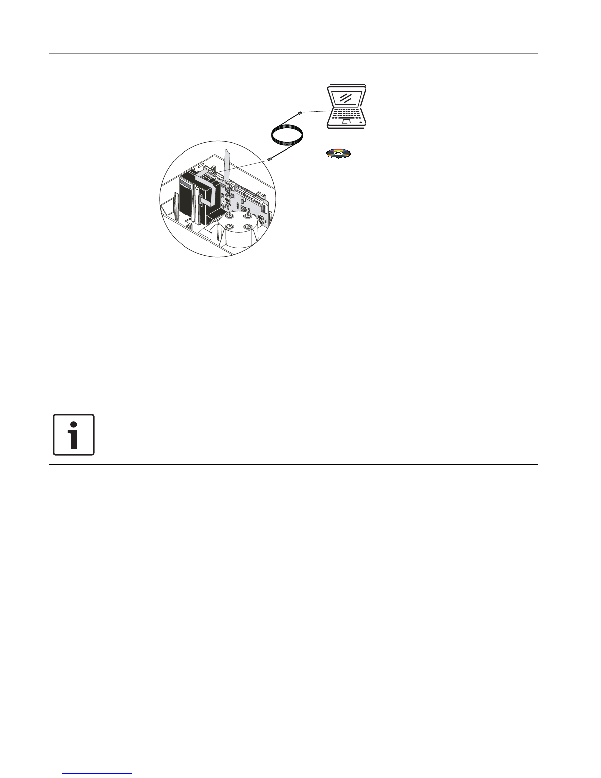
3.5.5 FAS-ASD-DIAG Diagnostic Software
DIAG
Figure3.4: Diagnostic software for reading out unit status
The diagnostic software enables the saved and the current unit status, as well as the error
messages to be displayed on the PC or laptop.
The supplied diagnostics cable connects the aspirating smoke detector ("DIAG" connection on
the motherboard) to the PC. The FAS-ASD-DIAG version is connected to the PC via a USB port,
earlier DIAG versions via a COM port.
Diagnostic messages remain saved in the unit for at least 3 days in order to be able to evaluate
even short, sporadically occurring errors (e.g. in case of changed operating conditions).
Resetting the device via the diagnostic software deletes all saved diagnostic messages.
The software also allows the deletion of error messages.
Notice!
The diagnostic software can be used to save in file format all the stored and current
diagnostic data as well as any settings made. To be able to compare the data read out, save
each file under a different file name.
3.5.6 Remote indictors
A remote indicator must be connected if the aspirating smoke detector is not directly visible
or has been mounted in false ceilings or floors.
The external detector alarm display is installed in an obvious place in halls or entrances of the
building section or areas concerned.
Aspirating Smoke Detector Technical Specifications | en 19
Bosch Sicherheitssysteme GmbH Operation Guide 2018.04 | 2.0 | F.01U.130.926
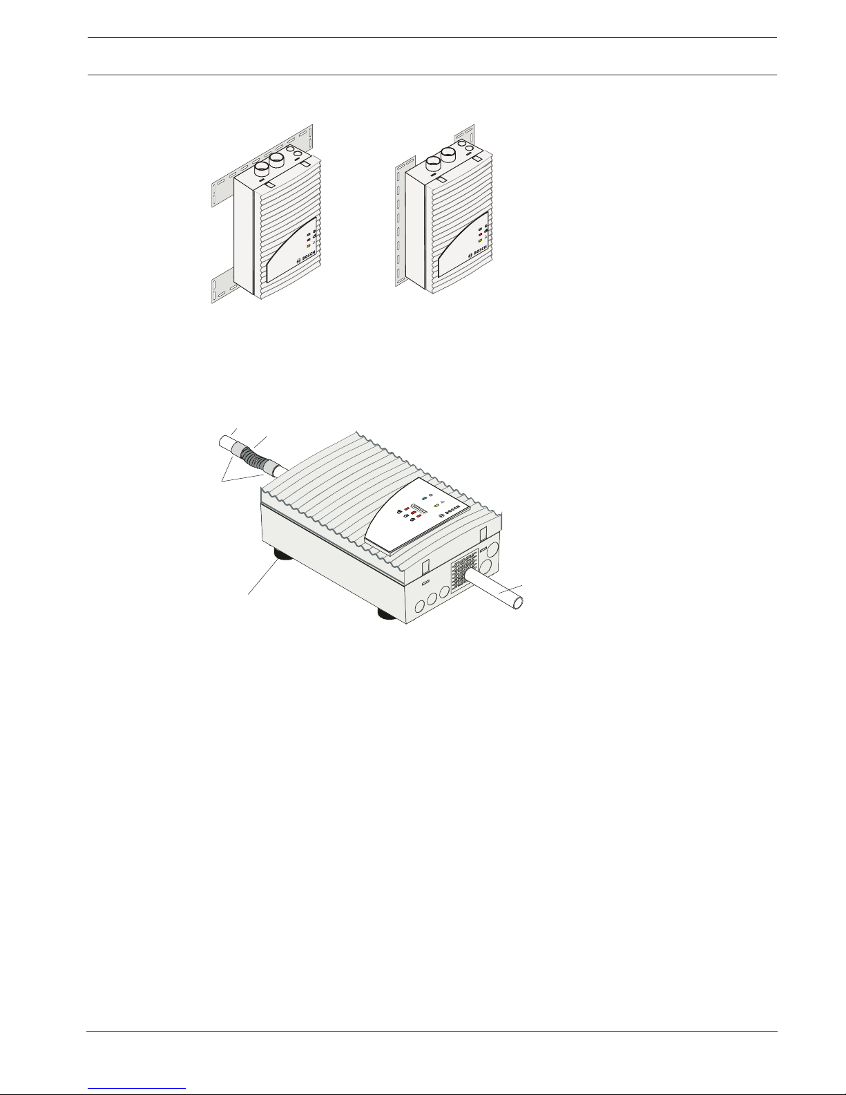
3.5.7 Device mounting
1
2
FAS
-420 series
FAS-420
series
Mounting for FCS-320 series Aspirating Smoke Detector
1 Horizontal installation
2 Vertical installation
The MT-1 unit mounting is used if a direct wall installation is not possible, e.g. installation on
racks.
3.5.8 Measures for Reducing Operating Noise
1
1
2
3
4
FAS-420 series
Absorption of the operating noises caused by airflows
1 Smoke aspiration pipe
2 Flexible hose
3 Fitting
4 Vibration absorbers
Vibration absorbers
The fans of the aspirating smoke detectors cause a noise level of approx.45dB(A). Mounting
the FCS-320 onto vibration absorbers can effectively reduce noise transmission through the
installation elements. This results in a reduction in the noise level from 1to 2dB(A).
Additional operating noises may be caused by vibrations on the pipe system, which are
generated by the air flowing through it. This can be remedied by inserting a corrugated hose
(approx.15cm long) between pipe system and aspirating smoke detector to create a flexible
transition.
In noise-sensitive areas, the sound level can also be reduced by installing a piece of plastic
pipe approximately 100mm long into the air outlet opening of the unit. This is done by
breaking out the pre-punched opening in the protective grille (e.g. using a small edge cutter).
20 en | Technical Specifications Aspirating Smoke Detector
2018.04 | 2.0 | F.01U.130.926 Operation Guide Bosch Sicherheitssysteme GmbH
3.6 Pipe system components
3.6.1 Overview
FAS-420-TM
ser
ies
A
A
A
4
5
3
2
7
6
8
9
10
11
12
13
1
14
A
B
Pipe system components
A Pipe system connection
B Smoke aspiration pipe
1 Connection for test
adapter
2 T-fitting
3 Air filter
4 Water separator
5 Detonation safety barrier
(not permitted for
EN54‑20 or ISO
7240-20)
6 90° pipe bend
7 Aspiration hose for
ceiling lead-through
8 Ceiling Lead-through
9 Fitting
10 Double threaded joint
11 90° pipe elbow
12 45° pipe elbow
13 Aspiration reduction
14 End cap
During planning/design, a distinction is drawn between area monitoring and equipment
monitoring. For both applications, PVC pipes and halogen-free pipes can be used but the
restrictions of EN 54.20 must be observed. The pipes used for equipment monitoring should
be halogen-free.
The figure shows essential accessory components that can be selected for the application
concerned.
The pipe system must be constructed using pipes with an external diameter of 25 mm and the
associated fittings.
If the maximum permissible pipe lengths are used, then for the pipe returns, pipes with an
exterior diameter of 40mm and the appropriate fittings must be used.
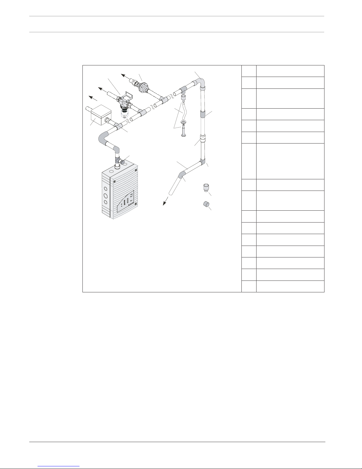
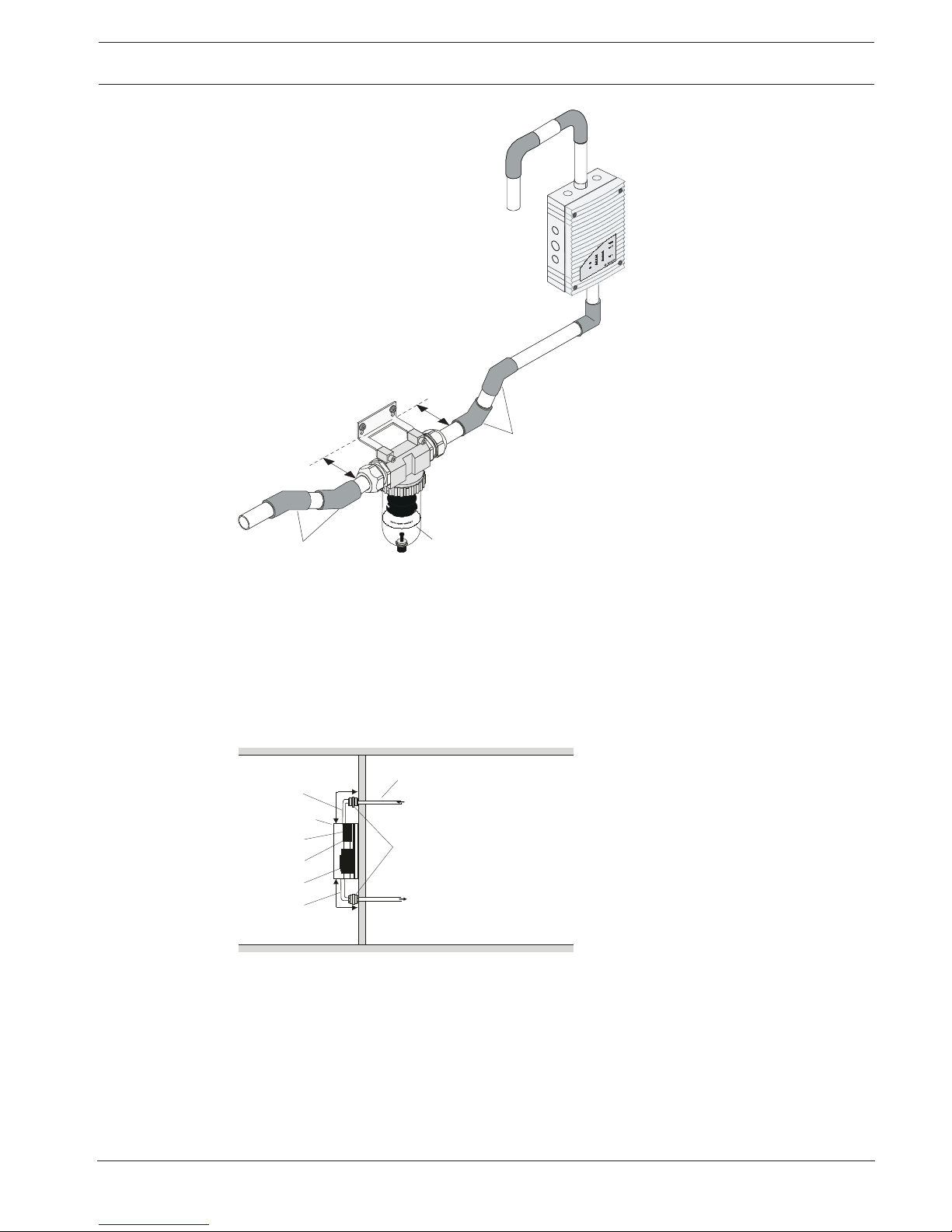
Blowing-out system
In areas that are susceptible to dust particles or icing, it may be necessary to blow out the
aspiration pipe system and its air sampling openings. The figure below shows a manual
blowing-out system with a three-way tap.
Aspirating Smoke Detector Technical Specifications | en 21
Bosch Sicherheitssysteme GmbH Operation Guide 2018.04 | 2.0 | F.01U.130.926
FAS-420-TM series
A
1
2
B
Components of manual blowing-out systems
A Blast air supply connection
B Pipe system connection
1 Three-way tap
2 25mm aspiration pipe
Aspiration reducing clips
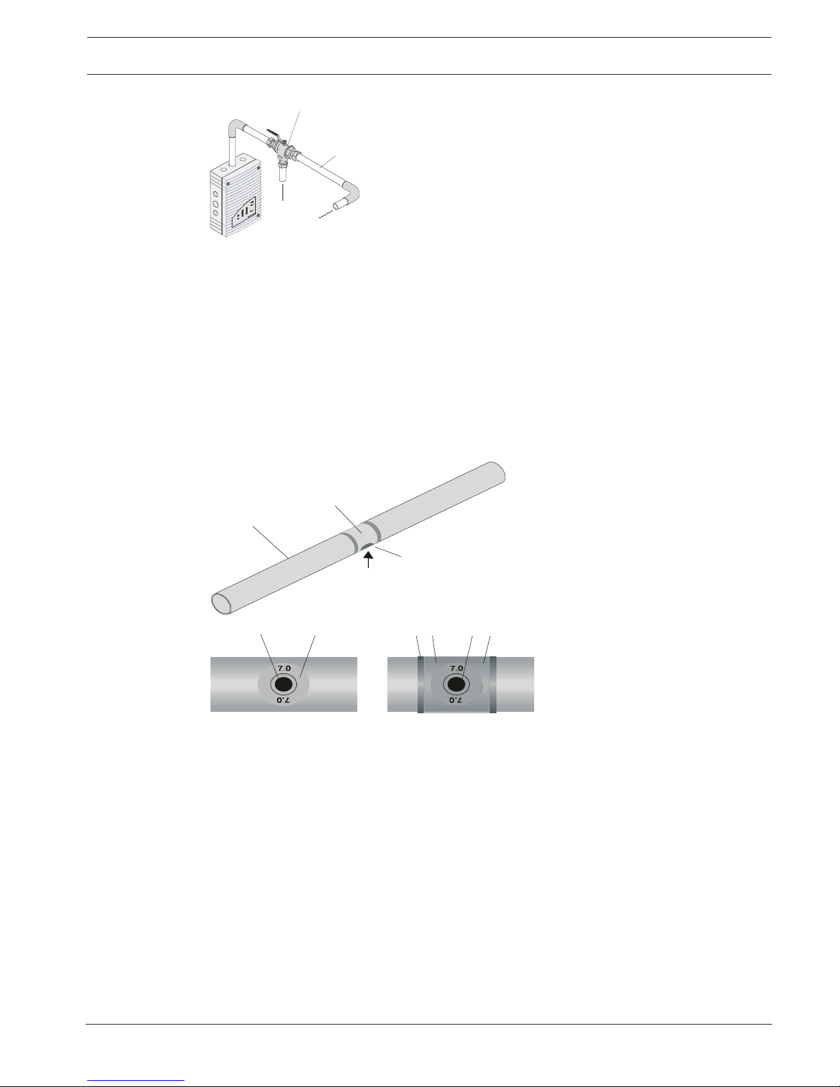
3.6.2 Air sampling openings
Aspiration reducing film sheets
An air sampling opening is a 10mm bore in the aspiration pipe that is covered with a patented
aspiration reducing film sheet with the required opening diameter. The size of the opening
depends on the structure of the pipe system (see Planning).
The aspiration reducing film sheet is secured with marking tape to prevent it from becoming
displaced. The marking tape is a transparent sticky film with red edges and a 10 mm hole. It is
placed over the aspiration reducing film sheet so that the air sampling opening is not
concealed and can be seen from long distances.
1
3
36
2
4
4
45
2
Air sampling opening with aspiration reducing film sheet and
marking tape
1 Smoke aspiration pipe
2 Air sampling opening
with aspiration reducing
film sheet
3 Marking tape for
aspiration reducing film
sheet
4 Air sampling opening
5 Fire red (RAL3000)
6 Transparent
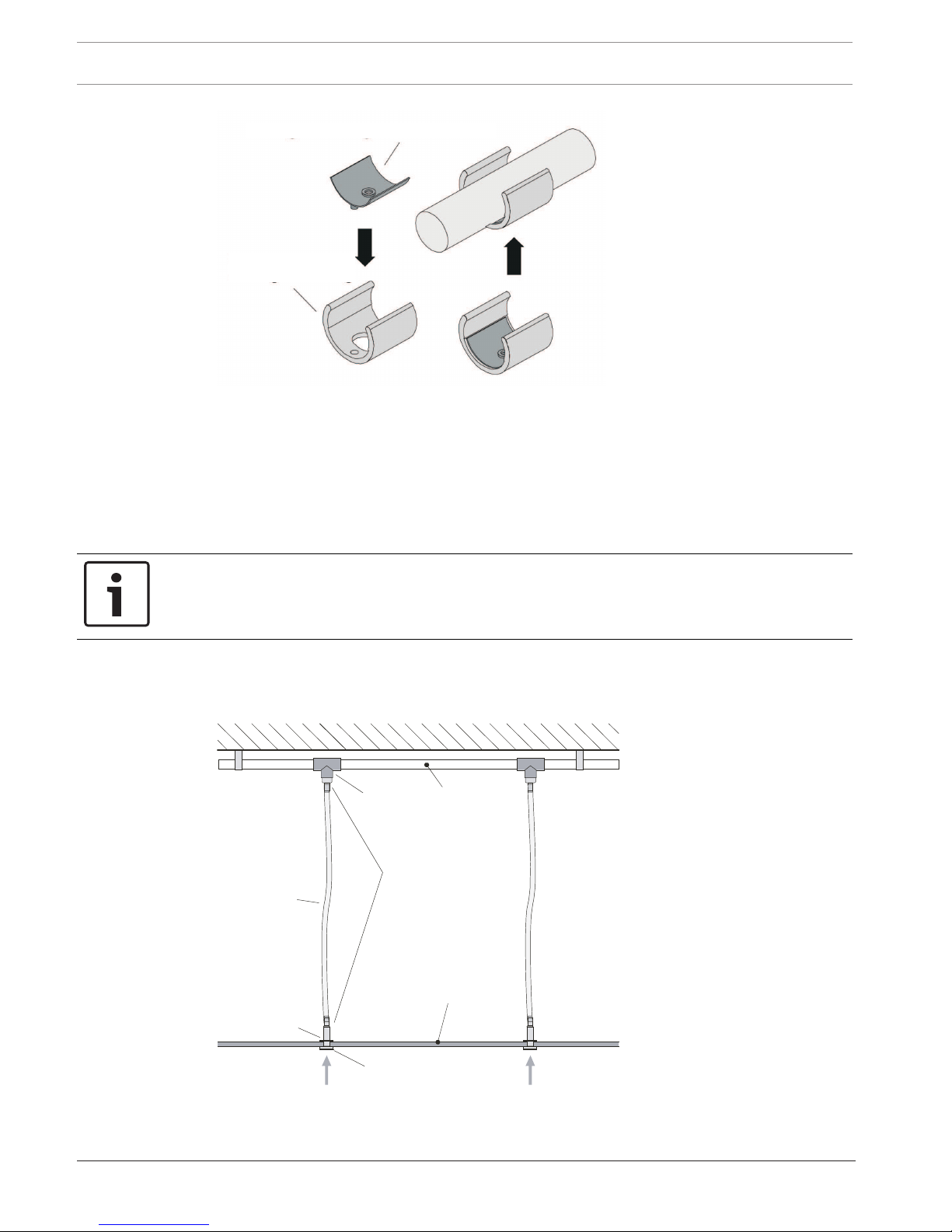
Aspiration reducing clips
In areas susceptible to obstructions or icing, special, patented ASD aspiration clips with
flexible aspiration reductions are used (see figure below).
22 en | Technical Specifications Aspirating Smoke Detector
2018.04 | 2.0 | F.01U.130.926 Operation Guide Bosch Sicherheitssysteme GmbH
1
2
Aspiration reduction for soiled areas and deep-freeze areas
1 Aspiration reduction for
deep-freeze facilities
2 ASD aspiration clip made of
plastic
During use in deep-freeze areas, the flexible aspiration reduction expands in the air sampling
openings and pushes the ice away during blowing out. The special plastic clip ensures that the
aspiration reduction remains at the defined location.
As the clips are more stable under pressure and the elastic rubber insert significantly
improves the cleaning effect, they are used for all plans and designs which require a blow-off
system due to environmental influences (e.g. increased exposure to dust).
Notice!
The standard AF-x aspiration reducing film sheets and the marking tapes are not suitable for
use in low-temperature areas.
The aspiration reductions with plastic clips are available separately.
3.6.3 Ceiling Lead-through Adapter
1
2
3
4
6
7
8
9
5
Ceiling lead-throughs
1 Ceiling
2 T-fitting
3 Pipe system
4 Complete ceiling lead-
through
5 Aspiration hose for ceiling
lead-through
6 False ceiling
7 Knurled nut
8 Aspiration reducing film
sheet
9 Aspiration
Aspirating Smoke Detector Technical Specifications | en 23
Bosch Sicherheitssysteme GmbH Operation Guide 2018.04 | 2.0 | F.01U.130.926
A concealed pipe system for area monitoring can be realized by installing in a false ceiling.
This requires the use of ceiling lead-throughs in the false ceiling. The ceiling lead-through can
be used with a false ceiling thickness of up to approx. 35mm.According to the planning and
design guidelines, the ceiling lead-throughs are fitted with aspiration reducing film sheets with
defined air sampling openings and connected to the pipe system by means of aspiration
hoses.
If these hoses exceed a maximum of 1m in length, the plan according to Section3Planning
applies. If structural circumstances dictate that lengths in excess of 1m are used, the pipe
system has to be calculated accordingly.
3.6.4 Air-Return Pipe for Pressure Areas and Atmospheric Loads
P1
P2
5
1
FAS / FCS
2
3
4
Principle of air return
P1/P2 Pressure areas 1 and 2
1 Detector module
2 Airflow sensor
3 Aspiration unit
4 Air-return pipe
5 Pipe system
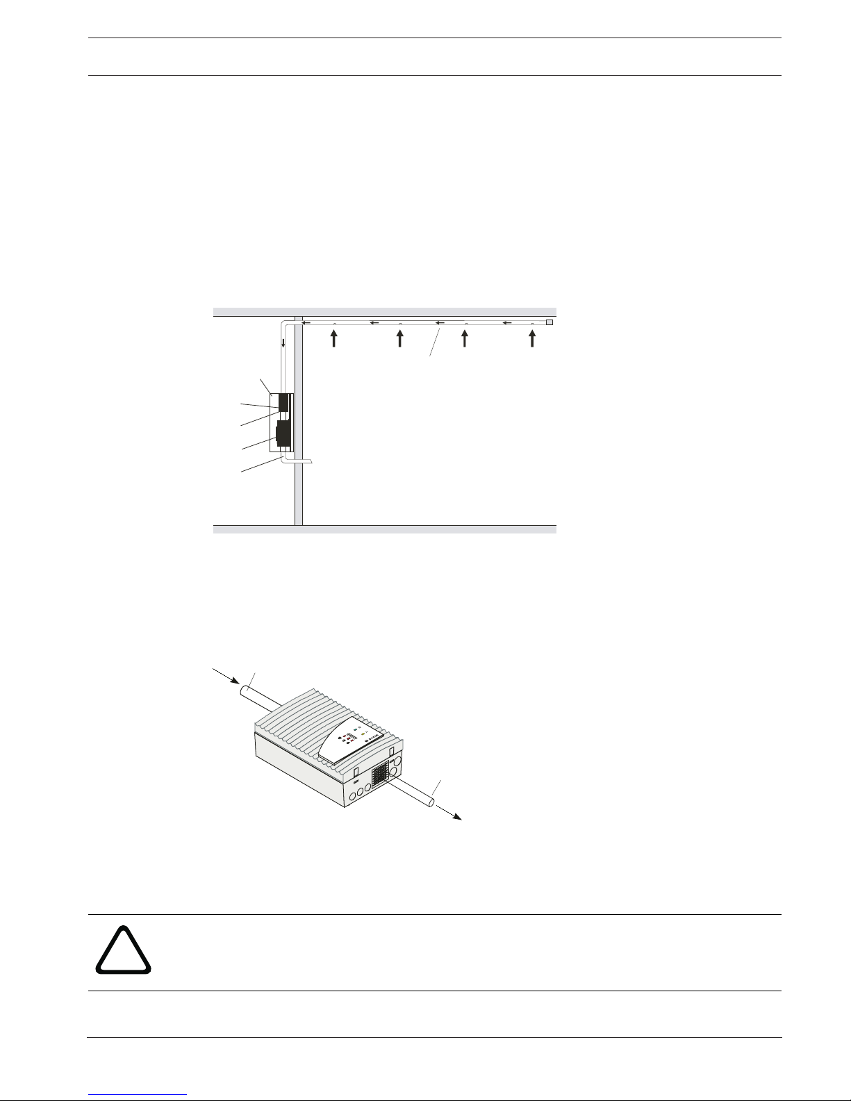
If the aspirating smoke detectors and the pipe system are installed in areas with varying air
pressure, the aspirated air must be returned to the pressure area of the pipe system. The airreturn pipe can serve to equalize pressure or to prevent atmospheric loads (e.g. odors) in
neighboring spaces.
1
2
FAS-420 series
FCS-320 with air-return pipe
1 Smoke aspiration pipe
2 Air-return pipe
The air-return pipe is connected to the air exhaust duct inside the FCS-320 through the
ventilation grille. This requires the pre-punched opening in the protective grille to be broken
out.
!
Caution!
The air-return pipe of the smoke aspiration system should not exceed 2m. Longer returns
must be checked individually.

24 en | Technical Specifications Aspirating Smoke Detector
2018.04 | 2.0 | F.01U.130.926 Operation Guide Bosch Sicherheitssysteme GmbH
3.6.5 Air filters for dusty areas
In areas with interference to the environment such as, e.g. dust, an air filter is to be used to
protect the smoke detection system. The standard air filter used is the type FAS-ASD-FL,
consisting of a plastic housing with two pipe connections. If the air filters are dirty, then the
filter inserts must be changed by opening the filter housing.
In order to extend the maintenance intervals, one air filter can be installed in every output
pipe instead of one air filter inside the main sampling pipe. The same design specifications
shall apply as stated in the projection tables in the appendix.
FAS-ASD-FLFAS-ASD-FLFAS-ASD-FLFAS-ASD-FL
FAS/FCS
Furthermore, in order to extend the maintenance intervals, several air filters can be installed
in parallel in the main sampling pipe. This requires the main sampling pipe to be split into one
or several pipes and to be equipped with the same air filter or the combination of air filters.
The individual pipes can then alternatively be either combined again to one main sampling
pipe or be separately continued into the monitoring area(s). The same design specifications
for the individual air filters shall apply as stated in the projection tables in the appendix.
3.6.6 Water Separator for Humid Areas
If the smoke aspiration system is operated in environments where condensate can form in the
aspiration system, a water separator is used. Condensate can form with sharp temperature
fluctuations and in areas where fresh air is monitored.For areas with extremely high humidity,
the FAS-ASD-WS Water Separator can be used, for example.
The FAS-ASD-WS Water Separator is integrated at the lowest point in the pipe system
downstream of the air filter and the aspirating smoke detector. The 45° pipe elbow permits
optimum distance from the wall.
Aspirating Smoke Detector Technical Specifications | en 25
Bosch Sicherheitssysteme GmbH Operation Guide 2018.04 | 2.0 | F.01U.130.926
1
2
3
3
FAS-420-TM series
FAS‑ASD‑WS Water Separator for condensing water vapor
and collecting condensate from the pipe system
1 Water separator
2 Pipe system connection
3 45° pipe elbow
The FAS‑ASD‑WS Water Separator can be operated in a temperature range from 0°C to
+50°C. The sintered metal filter in the water separator has a pore width of 50µm and causes
an additional rough absorption of soil particles.The FAS-ASD-WS is supplied with an angle
support and PG cable glands. The 45° pipe elbows (4 units) must be ordered separately.
3.6.7 Detonation Safety Barrier for Potentially Explosive Areas
Ex
FAS / FCS
1
6
7
2
3
4
5
> 1 m
> 1 m
Detonation safety barrier in the aspiration pipe system and if
necessary in the air-return pipe
1 Metal pipe
2 Detector module
3 Airflow sensor
4 Aspiration unit
5 Air-return pipe
6 Pipe system
7 Detonation safety barrier
Vapor/air and/or gas/air mixture ignition in the aspirating smoke detector may result in pipe
explosion or detonation. This depends on the composition, concentration, temperature, and
pressure of the flammable mixture.
The detonation safety barrier is a flame trap that is flame-proof in the face of pipe explosions
(deflagrations) and detonations.

26 en | Technical Specifications Aspirating Smoke Detector
2018.04 | 2.0 | F.01U.130.926 Operation Guide Bosch Sicherheitssysteme GmbH
In normal operation, the steam and gas mixtures flow in any direction through the safety
barrier. An ignition of the mixture in the upstream aspirating smoke detector will cause the
developing detonation to be arrested. Ignition is prevented by the flame filter. Combustion of
the mixture in the flame filters may cause a rebound of the detonation front. To prevent this, a
minimum pipe length of 1.0m between the installation point of the detonation safety barrier
and a possible ignition source (aspirating smoke detector) must be maintained. Permanent
fire prevention is thus achieved indirectly.
!
Caution!
The connecting pipe between the aspirating smoke detector and the detonation safety barrier
must be made of metal. During installation, care must be taken to ensure that the threaded
connections are bolted together gas-tight using synthesol or sealing tape.
3.7 Scope of Delivery: Smoke Aspiration System
Basic devices and accessories
Designation product ID
FCS-320-TP1 Standard unit F.01U.141.197
FCS-320-TP2 Standard unit F.01U.141.198
DM-TP-50(80) Detector module 4.998.143.394
DM-TP-10(25) Detector module 4.998.143.395
DM-TP-01(05) Detector module 4.998.143.396
TITANUS MT-1 MT-1 device mounting for aspirating smoke detector 4.998.143.410
FAS-ASD-DIAG DIAG diagnostic software including connection cable, for
USB port
F.01U.033.505
FCA‑320‑Reset Reset board F.01U.141.199
FCS-320-IK Installation kit F.01U.141.201
RAS Test Pipe Test pipe 4.998.148.848
RAS Test
Adapter
Test Adapter 4.998.148.849
Pipe system components
Designation product ID
FAS-ASD-PHF16 Polywell aspiration hose, flexible, black, halogen-free F.01U.029.719
FAS-ASDTRPG16
Ring nut with PG16 internal thread, 5per set F.01U.029.721
FAS-ASD-CSL Quick-lock coupling, straight, PG16 internal thread F.01U.029.720
FAS-ASD-3WT Three-way tap, incl. fittings, for 25mm pipe system F.01U.029.718
FAS-ASD-F Flange for ventilation duct F.01U.029.722
FAS-ASD-AR Aspiration reduction, with 10mm bore for attaching an
aspiration reducing film sheet, 10 per set
F.01U.029.724

Aspirating Smoke Detector Technical Specifications | en 27
Bosch Sicherheitssysteme GmbH Operation Guide 2018.04 | 2.0 | F.01U.130.926
Designation product ID
FAS-ASD-CLT Ceiling lead-through, white, ABS, 10 per set F.01U.029.725
FAS-ASD-AHC Aspiration hose (PE) for ceiling lead-through F.01U.029.727
FAS-ASD-DSB Detonation safety barrier for 25mm pipe system F.01U.029.716
FAS-ASD-WS Water separator with sintered metal filter and manual
drain valve, including mounting bracket and PG cable
glands for 25mm pipe system
F.01U.029.717
FAS-ASD-FL Large air filter box, for 25mm pipe system, inc. 1 filter
set and two PG29 screw connections
F.01U.029.714
FAS-ASD-RFL Replacement filter set for large air filter box F.01U.029.715
Notice!
Four 45° pipe elbows are required to install the FAS-ASD-WS water separator.
Air sampling opening components
Designation product ID
Marking tape for aspiration reducing film sheet AF-BR, 10 units. 4.998.143.413
Aspiration reducing film sheet 2.0mm AF-2.0, 10 units. 4.998.143.416
Aspiration reducing film sheet 2.5mm AF-2.5, 10 units. 4.998.143.417
Aspiration reducing film sheet 3.0mm AF-3.0, 10 units. 4.998.143.418
Aspiration reducing film sheet 3.2mm AF-3.2, 10 units. 4.998.143.419
Aspiration reducing film sheet 3.4mm AF-3.4, 10 units. 4.998.143.420
Aspiration reducing film sheet 3.6mm AF-3.6, 10 units. 4.998.143.422
Aspiration reducing film sheet 3.8mm AF-3.8, 10 units. 4.998.143.423
Aspiration reducing film sheet 4.0mm AF-4.0, 10 units. 4.998.143.424
Aspiration reducing film sheet 4.2mm AF-4.2, 10 units. 4.998.143.425
Aspiration reducing film sheet 4.4mm AF-4.4, 10 units. 4.998.143.426
Aspiration reducing film sheet 4.6mm AF-4.6, 10 units. 4.998.143.427
Aspiration reducing film sheet 5.0mm AF-5.0, 10 units. 4.998.143.428
Aspiration reducing film sheet 5.2mm AF-5.2, 10 units. 4.998.143.429
Aspiration reducing film sheet 5.6mm AF-5.6, 10 units. 4.998.143.430
Aspiration reducing film sheet 6.0mm AF-6.0, 10 units. 4.998.143.431
Aspiration reducing film sheet 6.8mm AF-6.8, 10 units. 4.998.143.432
Aspiration reducing film sheet 7.0mm AF-7.0, 10 units. 4.998.143.433

28 en | Technical Specifications Aspirating Smoke Detector
2018.04 | 2.0 | F.01U.130.926 Operation Guide Bosch Sicherheitssysteme GmbH
Notice!
Plastic clips for deep-freeze facilities and blowing-out systems are sold separately.
3.8 Technical data
3.8.1 FCS-320 Series Aspirating Smoke Detectors
Electrical
Power supply 15VDC to 33VDC
auxiliary power supply 14VDC to 30VDC
Current consumption from auxiliary power supply
(at24V)
FCS-320‑TP1
FCS-320-TT1
FCS-320‑TP2
FCS-320‑TT2
– Starting current, fan voltage 6.9V 300mA 330mA
– Starting current, fan voltage 9V 300mA 330mA
– On standby, fan voltage 6.9V 200mA 230mA
– On standby, fan voltage 9V 260mA 310mA
– On alarm, fan voltage 6.9V 230mA 290mA
– On alarm, fan voltage 9V 290mA 370mA
Mechanics
Displays on the device FCS-320-TP1/FCS-320-TP2
– Operation Green LED
– Fault Yellow LED
– Alarm 1 red LED/2 red LEDs
Displays on the device FCS-320-TT1/FCS-320-TT2
– Operation Green LED
– Fault Yellow LEDs
– Level display 1 x / 2 x smoke level display, each
with 10segments (1–10)
– Alarm 1 x 3 / 2 x 3 red LEDs for info alarm,
pre-alarm and main alarm
Conical duct connections for Ø25mm
– Aspiration pipe 1 pipe/2 pipes
– Air-return pipe 1 pipe
Cable bushings 5 x M 20 and 2 x M 25
Dimensions (H x W x D) 292 x 200 x 113mm
Weight Approx. 1.5kg

Aspirating Smoke Detector Technical Specifications | en 29
Bosch Sicherheitssysteme GmbH Operation Guide 2018.04 | 2.0 | F.01U.130.926
Housing material Plastic (ABS)
Housing color Papyrus white (RAL 9018)
Environmental conditions
Protection category as per EN 60529 IP 20
Permissible temperature range of aspirating smoke
detector
-20°C to +60°C
Permissible relative humidity (non-condensing) 10 to 95%
Special features
sound power level 45 dB(A)
Max. response sensitivity (max. light obscuration)
– DM‑TP‑50(80) Detector Module 0.5%/m (0.8%/m) *
– DM‑TP‑10(25) Detector Module 0.1%/m (0.25%/m) *
– DM‑TP‑01(05) Detector Module 0.015%/m (0.05%/m) *
Life cycle of the fan (12V) 43,000 hrs at 24°C
* The sensitivity value is based on measurements with standard test fires (old value in
brackets).
3.8.2 Pipe System
FCS-320-TP1
FCS-320-TT1
FCS-320-TP2
FCS-320-TT2
Maximum pipe length 300m 2 x 280m
Maximum number of air sampling openings 32 2 x 32
Maximum size of monitoring area 2880m
2
5760m
2
Permissible temperature range
– PVC pipe system 0°C to +60°C
– ABS pipe system -40°C to +80°C
3.8.3 Smoke Aspiration System Components
Water separator (FAS‑ASD‑WS)
Features For use in areas with very high humidity
Plastic housing with manual drain valve
Sintered metal filter
PG cable glands for 25mm pipe system
Incl. assembly bracket
Dimensions (H x W x D) 210 x 170 x 90mm
Weight Approx. 1.4kg

30 en | Technical Specifications Aspirating Smoke Detector
2018.04 | 2.0 | F.01U.130.926 Operation Guide Bosch Sicherheitssysteme GmbH
Filterbox, large (FAS‑ASD‑FL)
Features For use in areas with increased exposure to dust
Incl. filter set and two PG29 cable glands
Housing material ABS plastic
Housing color Light gray RAL 7035
Dimensions (H x W x D) 194 x 122 x 96mm
Application temperature
range
-30°C to +70°C
Replacement filter set, large (FAS‑ASD‑RFL)
Features Set comprising one fine, one medium and one coarse filter
insert (60ppi, 45ppi and 25ppi)
Application temperature
range
-30°C to +70°C
Detonation safety barrier (FAS‑ASD‑DSB)
Type PROTEGO Type EG IIA
Explosion group II A
Flame filter 3-way
Gap width 0.7mm
Pipe connection thread G 3/4 inch, incl. transition thread on one side for connecting
to the aspiration pipe system
Length x diameter 112mm x 80mm
Certification EC type-tested
Three way tap (FAS‑ASD‑3WT)
Features With 3 transition threads for connection to a 25mmpipe
system
Operating pressure Max. 10bar
Housing material PVC plastic
Seal Teflon (PTFE)
Length 131mm
Application temperature
range
0°C to +50°C
Ceiling lead-through (FAS‑ASD‑CLT) with aspiration hose (FAS‑ASD‑AHC)
Maximum false ceiling
thickness
35mm

Aspirating Smoke Detector Technical Specifications | en 31
Bosch Sicherheitssysteme GmbH Operation Guide 2018.04 | 2.0 | F.01U.130.926
Max. length of aspiration
hose per ceiling leadthrough
1m
Ceiling lead-through fitting
material
ABS
Aspiration hose material PE
Color of aspiration hose
and ceiling lead-through
White
Application temperature
range
-40°C to +80°C

32 en | Planning Aspirating Smoke Detector
2018.04 | 2.0 | F.01U.130.926 Operation Guide Bosch Sicherheitssysteme GmbH
4 Planning
Basic information on the relevant topics can be found in
– Regulations, page 32
– Principles of Pipe Planning, page 33
– Airflow monitoring, page 36
– Defining the Response Sensitivity, page 37
– Planning Limits, page 38.
The following sections describe plans with standard requirements for airflow monitoring:
– Standard Pipe Planning, page 39
– Planning for Long Pipe Feed Lines, page 58
– Simplified Pipe Planning, page 55
The pipe plan for more sensitive airflow monitoring is described in
– Pipe Planning for Single-Hole Monitoring, page 49.
The plan for monitoring air-conditioning ducts is described in
– Planning for Forced Airflow, page 69.
The principles for measuring power supply and pipe length are contained in
– Power Supply, page 76.
4.1 Regulations
The planning regulation below is based on the system limits of the FCS-320 series. Here, the
corresponding national regulations of the countries in their respectively applicable version
must be adhered to and planning must be adjusted to these.
The planning for the aspirating smoke detector in accordance with EN 54‑20 or ISO 7240-20 is
described below. The basic conditions are specified in Regulations. Planning must be carried
out in accordance with Standard Pipe Planning. In addition to Standard Pipe Planning, special
applications are also bound by the restrictions of the planning notes in accordance with
Planning with Single-hole Monitoring and the following sections. These must be taken into
account from the start in the case of any special planning processes.
Planning options in accordance with EN 54‑20 or ISO 7240‑20:
Various technical solutions are available to suit different planning criteria. The following table
lists the chapters in which the solutions are described.
Planning criteria Technical solution Principles Restriction
Area monitoring in
general
Basic planning Section
Standard Pipe
Planning
Detection of failure of a
single opening
Single-hole monitoring
planning
Section
Standard Pipe
Planning
Section Pipe
Planning for
Single-Hole
Monitoring
Equipment protection/
cabinet monitoring
Simplified pipe planning Section
Standard Pipe
Planning
Section
Simplified Pipe
Planning
Long supply lines Planning with long supply
lines
Section
Standard Pipe
Planning
Section Planning
for Long Pipe
Feed Lines

Aspirating Smoke Detector Planning | en 33
Bosch Sicherheitssysteme GmbH Operation Guide 2018.04 | 2.0 | F.01U.130.926
Planning criteria Technical solution Principles Restriction
Reducing transport time Planning with acceleration
openings
Section
Standard Pipe
Planning
Section Planning
with Acceleration
Openings, page
59
Ventilation ducts Planning for forced airflow Section
Standard Pipe
Planning
Section Planning
for Forced Airflow,
page 69
EN 54‑20 or ISO 7240‑20
For VdS systems, compliance is also required with the following guidelines:
– "Guideline for automatic fire detection systems, planning and installation", VdS
Schadenverhütung GmbH, Cologne (VdS2095)
– The guideline "Installation protection for electrical and electronic systems" VdS
Schadenverhütung GmbH, Cologne (VdS2304)
– The "Planning Aspirating Fire Detectors" data sheet from VdS Schadenverhütung GmbH,
Cologne (VdS 3435)
The applicable national regulations must also be observed, for example in Germany:
– DIN VDE0833 parts1 and 2 "Alarm systems for fire, intrusion and hold-up"
– Additional provisions for the installation of fire detection systems, which are published by
fire directors of fire departments, by the construction supervision authorities or by the
construction law authorities that have only local validity.
Notice!
For planning, the system limits in accordance with Planning Limits are to be observed.
Select airflow monitoring and the associated planning limits (see Airflow Monitoring) and
check these for any restrictions imposed by country-specific regulations.
If the on-site planning deviates from the standard plans described below, this must always be
checked with activation attempts for correct detection of a malfunction and a fire. A special
plan may be required.
Plans not contained in the operation guide must be requested.
4.2 Principles of Pipe Planning
The aspiration pipe network must be designed such that all possible fires in the monitoring
area can be dealt with at an early stage.
The number of air sampling openings and the structure of the pipe system depend on the size
and geometry of the monitoring range. The pipe system must be laid out according to the
planning guidelines in this chapter, taking into account the following issues:
Symmetrical structure
The pipe system should preferably have a symmetrical structure, i.e.
– Same number of air sampling openings per pipe branch
– Same pipe branch lengths (should not exceed ±20% deviation)
– Same distance between neighboring air sampling openings on the smoke aspiration pipe
(should not exceed ±20% deviation).
Asymmetrical structure
If structural circumstances dictate that the pipe system is to be designed asymmetrically, the
following conditions apply:
– The number of air sampling openings and the length of the shortest and longest pipe
branch within the pipe system must not exceed a quantity ratio of 1:2.

34 en | Planning Aspirating Smoke Detector
2018.04 | 2.0 | F.01U.130.926 Operation Guide Bosch Sicherheitssysteme GmbH
– The distance between neighboring air sampling openings on the smoke aspiration pipe
must be equal (should not exceed ±20% deviation).
– The diameters of the air sampling openings are determined separately for each pipe
branch. The diameters depend on the total number of air sampling openings in the pipe
branch in question.
The figure shows a typical U-pipe system with three or six air sampling openings and the air
sampling opening diameters calculated according to Standard Pipe Planning.
A
B
FAS / FCS
2,5
3,4 3,6 3,8
3,0 2,35,25,2 3,0
0,35,2 2,35,25,2 3,0
0,35,2 2,35,25,2 3,0
A Symmetrical pipe system
B Asymmetrical pipe system
Tab.4.1: Example of a symmetrical and an asymmetrical U-pipe system
In many applications, greater distances between the aspirating smoke detector and the
aspiration pipe must be bridged. This is done using pipes with greater diameters (40mm),
which guarantees maximum planning (see also Planning for Long Pipe Feed Lines). However,
pipes with greater diameters restrict the length of the pipe system.
Branch length
To achieve short transport times for the smoke aerosols in the aspiration pipe and thus quick
detection, it is better to plan several short branches than fewer long ones (preferably U and
double U-pipe system).
Pipe configurations
Depending on the area geometry, five pipe configurations can be selected:
– I-pipe: pipe system without branches.
– U-pipe: pipe system that branches into two pipe branches.
– M-pipe: pipe system that branches into three pipe branches.
– Double U-pipe: pipe system that branches symmetrically into four pipe branches.
– Quadruple U-pipe: pipe system that branches symmetrically into eight pipe branches.

Aspirating Smoke Detector Planning | en 35
Bosch Sicherheitssysteme GmbH Operation Guide 2018.04 | 2.0 | F.01U.130.926
I
FAS / FCS
FAS / FCS
FAS / FCS
U
U/U
FAS / FCS
M
FAS / FCS
4U
Pipe configurations
I I-pipe system
U U-pipe system
M M-pipe system
U/U Double U-pipe system
4U Quadruple U-pipe system
Change of direction
Elbows and bends in the pipe system increase flow resistance. Therefore, they should only be
used where they cannot be avoided for structural engineering reasons. Light change of
direction (e.g. with 90 ° pipe bends or air sampling hose) are already approved as part of the
project according to EN 54-20 or ISO 7240-20 and need not be considered further.
Notice!
It is preferable to use pipe bends rather than pipe elbows.
The detection time will be influenced significantly by too high a number of changes of
direction.
Special cases
If the pipe system does not correspond to the planning guidelines described here owing to
structural circumstances, it must be calculated separately for the case in question on request.
Testing

36 en | Planning Aspirating Smoke Detector
2018.04 | 2.0 | F.01U.130.926 Operation Guide Bosch Sicherheitssysteme GmbH
For critical applications, test the secure detection with activation attempts. Check also
whether there is airflow at the individual air sampling openings.
Notice!
In order to increase transport speed in critical application areas, the fan voltage can be
increased from 6.9V to 9V.
Dual-detector dependency
One aspiration line must be assigned per detector module. Both detector modules of a device
must be evaluated independently of one another. Only one extinguishing area per smoke
aspiration system may be monitored.
FAS / FCS
Pipe configurations for dual detector dependency
Two alarm stages
To implement two alarm stages, a pipe adapter for the aspiration pipe system is required. The
two detector modules in the aspirating smoke detector require different response
sensitivities.
FAS / FCS
Pipe configurations for two alarm stages using the example of a U-pipe system
See also
– Standard Pipe Planning, page 39
– Planning for Long Pipe Feed Lines, page 58
4.3 Airflow monitoring
EN 54‑20 or ISO 7240-20 requires the detection of a 20-percent change in the airflow volume
by the detector module's airflow sensor. In order to achieve this, the activation threshold of
the airflow sensor must be set to level II. Alternatively, level I can also be used. It is
recommended that airflow calibration is carried out dependent on air pressure for both of
these settings. In systems that do not need to comply with EN 54‑20 or ISO 7240-20, any
threshold can be set. The smoke aspiration pipes are planned taking into account the
applicable national regulations for the country concerned.
Adapting the airflow sensitivity
The sensitivity of the airflow sensor must be adapted to the application. For example, a long
pipe system requires a sensitive setting of the airflow sensor. The activation threshold and
thus the sensitivity of the airflow sensor can be set on 4 levels. Breakages and obstructions
must be accurately detected in the event of a malfunction.

Aspirating Smoke Detector Planning | en 37
Bosch Sicherheitssysteme GmbH Operation Guide 2018.04 | 2.0 | F.01U.130.926
Setting the airflow sensitivity
Level Activation threshold Sensitivity
I Low (+/- 10% volume flow change) Very high
II Average (+/- 20% volume flow change) High
III High (+/- 30% volume flow change) Average
IV Very high (+/- 50% volume flow change) Low
Level I II III IV
Complies with EN 54‑20 or ISO
7240-20
Activation threshold Small Average Large Very large
Sensitivity Very high High Average Low
Notice!
Selection of the largest possible, precisely still-approved level is recommended.
Dynamic airflow sensors
The airflow monitoring of the unit makes it possible to detect breaks at the end of pipes and
identify sudden obstruction of individual air sampling openings (e.g. following tampering with
the pipe system). Because these dynamic airflow sensors are only active if level I was selected
for the airflow monitoring, the points outlined under "Level I restrictions" must be taken into
consideration.
Restrictions
Airflow monitoring may only be set to level I if
– planning was carried out in accordance with "single-hole monitoring"
– the airflow sensor was calibrated dependent on the air pressure
– and no larger airflow fluctuations can occur.
Air pressure differences
There must be equal air pressure along the length of the aspiration pipe.
Notice!
If the aspirating smoke detectors and the pipe system are positioned in areas with different
air pressures, the air aspirated by the FCS-320 must be returned to the pressure area of the
pipe system (see Air-Return Pipe for Pressure Areas and Atmospheric Loads).
4.4 Defining the Response Sensitivity
The sensitivity of smoke aspiration systems can be divided into certain fire sensitivity classes
in accordance with EN 54‑20 or ISO 7240-20. These fire sensitivity classes describe specific
examples of ways in which the systems can be applied. The permissible system plans given in
Standard Pipe Planning can be determined for each classification.Smoke aspiration systems
with a higher fire sensitivity class according to EN 54‑20 or ISO 7240-20 also satisfy the
requirements of the lower classes.

38 en | Planning Aspirating Smoke Detector
2018.04 | 2.0 | F.01U.130.926 Operation Guide Bosch Sicherheitssysteme GmbH
Class Description Application example
A Aspirating smoke detector with
extremely high sensitivity
Very early detection: significant smoke
dilution through air conditioning in IT
areas
B Aspirating smoke detector with
increased sensitivity
Early detection: significant time gains
thanks to very early fire detection
(without air condition)
C Smoke aspiration system with normal
sensitivity
Normal detection: fire detection with the
advantages of smoke aspiration systems
Notice!
Depending on the number of air sampling openings, fire sensitivity classes A, B and C can all
be achieved with the detection modules available.
The table shows the sensitivities you can choose from
Response sensitivity (main alarm)
DM-TP-50(80) Detector
Module
DM-TP-10(25) Detector
Module
DM-TP-01(05) Detector Module
Not permissible 0.8%/m (2%/m) light
obscuration
0.12%/m (0.4%/m) light
obscuration
Not permissible 0.4%/m (1%/m) light
obscuration (standard)
0.06%/m (0.2%/m) light
obscuration (standard)
1.0%/m (1.6%/m) light
obscuration
0.2%/m (0.5%/m) light
obscuration
0.03%/m (0.1%/m) light
obscuration
0.5%/m (0.8%/m) light
obscuration (standard)
0.1%/m (0.25%/m) light
obscuration
0.015%/m (0.05%/m) light
obscuration
Notice!
The sensitivity value is based on measurements with standard test fires (old value in
brackets).
4.5 Planning Limits
The following limit values must always be observed for the FCS-320 series:
Limiting values Maximum number of air sampling openings per detector
module
32
Maximum total pipe length 300m (2 x
280m)
Minimum pipe length between 2 air sampling openings 4m
Minimum pipe length between 2 air sampling openings 12m
The maximum monitoring area of an air sampling opening corresponds to the monitoring area
of point-type detectors in accordance with the applicable planning guidelines.

Aspirating Smoke Detector Planning | en 39
Bosch Sicherheitssysteme GmbH Operation Guide 2018.04 | 2.0 | F.01U.130.926
The maximum total monitoring area, the maximum total pipe length and the maximum number
of air sampling openings depend on the selected planning. They are also dependent on the
restrictions imposed by national regulations.
Depending on the planning selected, some restricted values may apply.
The values for the maximum number of air sampling openings, the maximum pipe length and
the maximum overall monitoring areas apply for each pipe system. Two pipe systems can be
connected to aspirating smoke detectors FCS-320-TP2 and FCS-320-TT2, each with two
detector modules.
4.6 Standard Pipe Planning
In order to plan in accordance with the EN 54‑20 or ISO 7240-20 standard, certain factors
must be known, such as the system sensitivity requirements, the number of air sampling
openings and the accessories needed for the application concerned. These factors can be
used to determine the appropriate standard-compliant construction of the pipe system using
the following chapter and the planning table in the appendix.
4.6.1 Determining the Necessary Accessories
As accessory components, e.g. filters, have a particular effect on the dimensions of pipe
planning, the appropriate accessory must be selected for the application concerned in
advance. Retrofitting an accessory, e.g. a fine filter, is largely only possible if a certain reserve
is planned in advance.
The following components must be taken into account in this regard:
– Air filter
– Water separator
– Three-way-tap
– Detonation safety barrier
See Section Smoke Aspiration System Components, page 29.
See also
– Smoke Aspiration System Components, page 29
– Smoke Aspiration System Components, page 29
4.6.2 Pipe Planning with Pipe Accessories
For the purpose of pipe system planning, the following planning table is available for all
selected pipe accessories.
– Planning without air filter
– Planning with FAS‑ASD‑FL air filter
Notice!
In order to improve the detection quality of a smoke aspiration system, an area can be
monitored with more detection points than required by national guidelines. However, to
calculate the necessary sensitivity of an aspirating smoke detector, the number of aspiration
points required by the standard must be used.
Procedure
In the following example, a plan with air filter with 8 openings, not fitted with any other
accessories, should satisfy class B. The red shaded areas show the potential plans with
different pipe shapes and fan voltage.

40 en | Planning Aspirating Smoke Detector
2018.04 | 2.0 | F.01U.130.926 Operation Guide Bosch Sicherheitssysteme GmbH
General Example
1. Selection:
Select the planning table with or without air filter,
as applicable.
Result:
Planning table and specified air filter
Select the planning table without air filter, Planning
without filter, page 41
2. Selection:
Select the number of air sampling openings from
the planning table. Note the possible sensitivity
classes.
Result:
Specified detector module with specified setting
and alarm threshold
In the Planning without filter, page 41 table, select
the column with eight air sampling openings (Number
of air sampling openings, 8)
3. Selection:
Select the sensitivity (sensitivity class) of the
system according to the gradation described in
Defining the Response Sensitivity.
Result:
Specified sensitivity class in accordance with EN
54‑20
In the Planning without filter, page 41 table, select
the response sensitivity you require (class A, B or C)
from the column highlighted in red. You must select
the class that corresponds to the installed detector
module and the configured sensitivity.
4. Selection:
Select other pipe components, such as a water
separator and detonation safety barrier.
Result:
Specified planning table
Select With water separator, page 42 .
5. Selection:
Select the possible pipe length for the relevant pipe
shape and fan voltage.
Result:
Specified planning in accordance with EN 54‑20 for
the previously specified parameters
In the With water separator, page 42 table, select the
pipe shape and fan voltage you require, and note the
permissible total pipe length.
You will find the planning tables in question in Planning without filter and Planning with air
filter.
Abbreviation Meaning CTN
DM Detector module DM‑01(05) DM-TP-01(05)
DM‑10(25) DM-TP-10(25)
DM‑50(80) DM-TP-50(80)
S Sensitivity (% LT/m)
MA Main alarm
PA Pre-alarm
l [m] Permissible total pipe length in
meters

Aspirating Smoke Detector Planning | en 41
Bosch Sicherheitssysteme GmbH Operation Guide 2018.04 | 2.0 | F.01U.130.926
Planning without filter
Number of air sampling openings
DM- S 1 2 3 4 5 6 7 8 9 10 11 12 … 32
01
(05)
0.015
(0.05)
MAA A A A A A A A A A A A A
0.03 (0.1) MAA A A A A A A A A A A A B
0.06 (0.2) MAA A A A A A A A A A A A C
0.12 (0.4) MAA A A A A A B B B B B B
10
(25)
0.1 (0.25) MAA A A A A A A A A B B B B
0.2 (0.5) MAA A A A B B B B B B B B
0.4 (1) MAA A B B B B C C C C C C
0.8 (2) MAA B B C C C
50
(80)
0.313
(0.5)
PA A A A A B B B B B B B B C
0.5 (0.8) MAA A A B B B B C C C C C
0.687
(1.1)
PA A A B B B C C C C C
1.0 (1.6) MAA B B C C C C

42 en | Planning Aspirating Smoke Detector
2018.04 | 2.0 | F.01U.130.926 Operation Guide Bosch Sicherheitssysteme GmbH
Without any other pipe accessories
Number of air sampling openings
Pipe
shape
U
Fans
1 2 3 4 5 6 7 8 9 10 11 12 … 32
I 6.9 77 77 77 77 77 77 77 77 76 l
[m]
≥9 100 100 100 100 100 100 100 100 100 100 100 100
U 6.9 120 120 120 120 120 120 120 120 120 120 120 120
≥9 150 150 150 150 150 150 150 150 150 150 150 150
M 6.9 170 170 170 170 170 170 170 170 170 170 170 170
≥9 180 180 180 180 180 180 180 180 180 180 180 180
2 x U 6.9 180 180 180 180 180 180 180 180 180 180 180 180
≥9 200 200 200 200 200 200 200 200 200 200 200 200
4 x U (1
DM)
6.9
≥9 300 300 300 300 300 300 300 300 300 300 300 300 300
With water separator
Number of air sampling openings
Pipe
shape
U
Fans
1 2 3 4 5 6 7 8 9 10 11 12 … 32
I 6.9 60 60 60 60 60 60 60 l [m]
≥9 80 80 80 80 80 80 80 80 80 80
U 6.9 110 110 110 110 110 110 110 110 110 110 110 110
≥9 110 110 110 110 110 110 110 110 110 110 110 110
M 6.9 110 110 110 110 110 110 110 110 110 110 110 110
≥9 160 160 160 160 160 160 160 160 160 160 160 160
2 x U 6.9 140 140 140 140 140 140 140 140 140 140 140 140
≥9 160 160 160 160 160 160 160 160 160 160 160 160

Aspirating Smoke Detector Planning | en 43
Bosch Sicherheitssysteme GmbH Operation Guide 2018.04 | 2.0 | F.01U.130.926
With detonation safety barrier
Number of air sampling openings
Pipe
shape
U
Fans
1 2 3 4 5 6 7 8 9 10 11 12 … 32
I 6.9 46 46 46 46 38 l [m]
≥9 68 68 68 68 68 68
U 6.9 60 60 60 60 60 60
≥9 60 60 60 60 60 60 60 60
M 6.9 80 80 80 80 80 80 70 70 70
≥9 120 120 120 120 120 120 120 120 120
2 x U 6.9 80 80 80 80 80 80 80 80
≥9 100 100 100 100 100 100 100 100
Results
The following modules can be used with the relevant settings for class B or A:
– 0.015% LT/m (0.05% LT/m) module – with a sensitivity of min. 0.12% LT/m (0.4% LT/m)
– 0.1% LT/m (0.25% LT/m) module – with a sensitivity of min. 0.2% LT/m (0.5% LT/m)
– 0.5% LT/m (0.8% LT/m) module – with setting 0.5% LT/m (0.8% LT/m)
System parameters possible:
– I-pipe system
9V fan voltage, max. 80m total pipe length for U-pipe system
– U-pipe system
6.9V fan voltage, max. 110m total pipe length
9V fan voltage, max. 110m total pipe length
– M-pipe system
6.9V fan voltage, max. 110m total pipe length
9V fan voltage, max. 160m total pipe length
– Double U-pipe system
6.9V fan voltage, max. 140m total pipe length
9V fan voltage, max. 160m total pipe length
Notice!
The sensitivity value is based on measurements with standard test fires (old value in
brackets).
I-pipe system for space protection
The diameters of the air sampling openings should be taken from the relevant table for each
pipe configuration:
1 pipe system
FCS-320-TP1
FCS-320-TT1
2 pipe systems
FCS-320-TP2
FCS-320-TT2
FAS / FCS
A
B
C D E L MF
A
B
C D E L MF
I-pipe system for space protection

44 en | Planning Aspirating Smoke Detector
2018.04 | 2.0 | F.01U.130.926 Operation Guide Bosch Sicherheitssysteme GmbH
Limiting values Min. distance: FCS-320 – 1st air sampling opening 4m
I-pipe system Max. distance: FCS-320 – 1st air sampling opening 20m
Max. distance: 1st air sampling opening – last air sampling opening
– With low fan voltage
– With high fan voltage
56m
80 m
Max. overall pipe length per pipe system (Ø 25mm)
– With low fan voltage
– With high fan voltage
76m
100m
Min. distance between 2 air sampling openings 4m
Max. distance between 2 air sampling openings 12m
Max. number of air sampling openings (n) per pipe system 13
I-pipe system Air sampling
opening
Number of air sampling openings
1 2 3 4 5 6 7 8 9 10 11 12 13
∅ air sampling
opening in
mm
a
A 7.0 6.0 5.2 4.6 4.2 3.8 3.6 3.4 3.0 3.0 2.5 2.5 2.5
B 6.8 5.2 4.6 4.2 3.8 3.6 3.4 3.0 3.0 2.5 2.5 2.5
C 5.6 4.6 4.4 4.0 3.8 3.4 3.2 3.0 3.0 3.0 2.5
D 5.0 4.4 4.0 3.8 3.4 3.4 3.0 3.0 3.0 2.5
E 4.4 4.2 3.8 3.6 3.6 3.4 3.0 3.0 3.0
F 4.2 3.8 3.8 3.6 3.4 3.4 3.0 3.0
G 4.0 3.8 3.6 3.6 3.4 3.2 3.0
H 4.0 3.8 3.6 3.4 3.2 3.0
I 3.8 3.6 3.6 3.2 3.2
J 3.8 3.8 3.2 3.2
K 3.8 3.8 3.4
L 4.0 3.8
M 4.0
a
Punch diameter of the aspiration reducing film sheet

Aspirating Smoke Detector Planning | en 45
Bosch Sicherheitssysteme GmbH Operation Guide 2018.04 | 2.0 | F.01U.130.926
U-pipe system for space protection
1 pipe system
FAS‑420‑TP1
FAS‑420‑TT1
2 pipe systems
FAS‑420‑TP2
FAS‑420‑TT2
FAS / FCS
FAS / FCS
A B C D I J
A B C D I J
U-pipe system for space protection
Limiting values Min. distance: FCS-320 – T-fitting 4m
U-pipe system Max. distance: FCS-320 – T-fitting 20 m
Max. branch length
– With low fan voltage
– With high fan voltage
50m
65m
Max. overall pipe length per pipe system (Ø 25mm)
– With low fan voltage
– With high fan voltage
120m
150m
Min. distance between 2 air sampling openings 4m
Max. distance between 2 air sampling openings 12m
Max. number of air sampling openings (n) per pipe system 20
U-pipe system Air sampling
opening
Number of air sampling openings
2 4 6 8 10 12 14 16 18 20
∅ air sampling
opening in mm
a
A 5.2 3.6 3.4 3.0 2.5 2.5 2.0 2.0 2.0 2.0
B 4.4 3.4 3.0 3.0 2.5 2.0 2.0 2.0 2.0
C 3.6 3.2 3.0 2.5 2.5 2.0 2.0 2.0
D 3.4 3.2 3.0 2.5 2.5 2.0 2.0
E 3.2 3.0 3.0 2.5 2.5 2.0
F 3.4 3.2 3.0 2.5 2.5
G 3.6 3.4 3.0 2.5
H 3.6 3.4 2.5
I 3.6 3.6
J 3.8

46 en | Planning Aspirating Smoke Detector
2018.04 | 2.0 | F.01U.130.926 Operation Guide Bosch Sicherheitssysteme GmbH
a
Punch diameter of the aspiration reducing film sheet
M-pipe system for space protection
1 pipe system
FCS-320-TP1
FCS-320-TT1
2 pipe systems
FCS-320-TP2
FCS-320-TT2
A B C D E F
A B C D E F
FAS / FCS
FAS / FCS
M-pipe system for space protection
Limiting values Min. distance: FCS-320 – last T-fitting 4m
M-pipe Max. distance: FCS-320 – last T-fitting 20 m
Max. branch length
– With low fan voltage
– With high fan voltage
46m
53m
Max. overall pipe length per pipe system (Ø 25mm)
– With low fan voltage
– With high fan voltage
170m
180m
Min. distance between 2 air sampling openings 4m
Max. distance between 2 air sampling openings 12m
Max. number of air sampling openings (n) per pipe system 21

Aspirating Smoke Detector Planning | en 47
Bosch Sicherheitssysteme GmbH Operation Guide 2018.04 | 2.0 | F.01U.130.926
M-pipe system Air sampling opening Number of air sampling openings
3 6 9 12 15 18 21
∅ air sampling
opening in mm
a
A 4.4 3.4 3.0 2.5 2.5 2.0 2.0
B 3.6 3.0 2.5 2.5 2.5 2.0
C 3.2 3.2 2.5 2.5 2.0
D 3.2 3.0 2.5 2.5
E 3.2 3.0 2.5
F 3.2 3.2
G 3.4
a
Punch diameter of the aspiration reducing film sheet
Double U-pipe system for space protection
1 pipe system
FCS-320-TP1
FCS-320-TT1
2 pipe systems
FCS-320-TP2
FCS-320-TT2
FAS / FCS
FAS / FCS
F
F
B
B
A
A
Double U-pipe system for space protection
Limiting values Min. distance: FCS-320 – last T-fitting 4m
Double U-pipe Max. distance: FCS-320 – last T-fitting 20 m
Max. branch length
– With low fan voltage
– With high fan voltage
40m
45m
Max. overall pipe length per pipe system (Ø 25mm)
– With low fan voltage
– With high fan voltage
180m
200m
Min. distance between 2 air sampling openings 4m
Max. distance between 2 air sampling openings 12m
Max. number of air sampling openings (n) per pipe system 24

48 en | Planning Aspirating Smoke Detector
2018.04 | 2.0 | F.01U.130.926 Operation Guide Bosch Sicherheitssysteme GmbH
Double U-pipe
system
Air sampling opening Number of air sampling openings
4 8 12 16 20 24
∅ air sampling
opening in mm
a
A 4.0 3.0 2.5 2.0 2.0 2.0
B - 3.4 3.0 2.5 2.0 2.0
C - - 3.0 3.0 2.5 2.0
D - - - 3.2 2.5 2.5
E - - - - 3.6 2.5
F - - - - - 3.6
a
Punch diameter of the aspiration reducing film sheet
Quadruple U-pipe system for space protection
1 pipe system
FCS-320-TP1
FCS-320-TT1
A B C D
FAS / FCS
Quadruple U-pipe system for space protection
Limiting values Min. distance: FCS-320 – last T-fitting 4m
Double U-pipe Max. distance: FCS-320 – last T-fitting 20 m
Max. branch length
– With high fan voltage 35m
Max. overall pipe length per pipe system (Ø 25mm)
– With high fan voltage 300m
Min. distance between 2 air sampling openings 4m
Max. distance between 2 air sampling openings 12m
Max. number of air sampling openings (n) per pipe system 32

Aspirating Smoke Detector Planning | en 49
Bosch Sicherheitssysteme GmbH Operation Guide 2018.04 | 2.0 | F.01U.130.926
Quadruple U-pipe
system
Air sampling opening Number of air sampling openings
8 16 24 32
∅ air sampling
opening in mm
a
A 3.20 2.5 2.0 2.0
B - 3.0 2.5 2.0
C - - 3.0 2.0
D - - - 2.5
a
Punch diameter of the aspiration reducing film sheet
See also
– Defining the Response Sensitivity, page 37
– Planning without filter, page 123
– Planning with air filter, page 125
4.7 Pipe Planning for Single-Hole Monitoring
Depending on the pipe configuration, the following system parameters are used to detect a
single air sampling opening or a particular number of obstructed air sampling openings.
Planning is to be carried out according to regulations specified in Standard Pipe Planning.
Additionally, the following limiting values and opening diameters must be observed. An
additional accessory (air filter, condensate separator etc.) can have an effect on the maximum
pipe length.
I-pipe system - single-hole monitoring
1 pipe system FCS-320TP1 FCS-320-TT1
2 pipe systems FCS-320TP2 FCS-320-TT2
FAS / FCS
A
B
C D E I JF
A
B
C D E I JF
I-pipe system for space protection
Limiting values Min. distance FCS-320– 1st air sampling opening 4m
I-pipe system Max. distance FCS-320 – 1st air sampling opening 20m
Max. distance: 1st air sampling opening – last air sampling opening
– With low fan voltage
– With high fan voltage
40m
60m
Max. overall pipe length (Ø 25mm)
– With low fan voltage
– With high fan voltage
60m
80m
Min. distance between 2 air sampling openings 4m
Max. distance between 2 air sampling openings 12m
Max. number of air sampling openings (n) per pipe system 10

50 en | Planning Aspirating Smoke Detector
2018.04 | 2.0 | F.01U.130.926 Operation Guide Bosch Sicherheitssysteme GmbH
I-pipe system Air sampling
opening
Number of air sampling openings
2 3 4 5 6 7 8 9 10
∅ air sampling
opening in mm
a
A 6.0 5.0 4.2 3.8 3.2 3.0 2.5 2.5 2.0
B 6.8 5.2 4.4 3.8 3.2 3.0 2.5 2.5 2.0
C - 5.2 4.6 4.0 3.6 3.0 3.0 2.5 2.5
D - - 4.6 4.0 3.6 3.4 3.0 3.0 2.5
E - - - 4.4 4.0 3.4 3.4 3.0 3.0
F - - - - 4.0 3.8 3.4 3.4 3.0
G - - - - - 3.8 3.8 3.4 3.4
H - - - - - - 3.8 3.8 3.4
I - - - - - - - 3.8 3.6
J - - - - - - - - 3.6
a
Punch diameter of the aspiration reducing film sheet
I-pipe system activation thresholds
Activation
thresholds
Number of openings 2 3 4 5 6 7 8 9 10
1 obstructed opening III III II I I — — — —
2 obstructed openings 0 0 III III II I I — —
3 obstructed openings 0 0 0 0 III III II I I
4 obstructed openings 0 0 0 0 0 0 III II I
5 obstructed openings 0 0 0 0 0 0 0 0 II
… will be recognized by the setting level x
— not possible, 0 not practical
Example
If 3 of a total of 7 air sampling openings are found to be obstructed, the switch for setting the
airflow monitoring should be set to level III.
Notice!
When planning in accordance with EN 54‑20 or ISO 7240-20, level I or II must always be set
for airflow monitoring.

Aspirating Smoke Detector Planning | en 51
Bosch Sicherheitssysteme GmbH Operation Guide 2018.04 | 2.0 | F.01U.130.926
U-pipe system - single-hole monitoring
1 pipe system
FCS-320-TP1
FCS-320-TT1
2 pipe systems
FCS-320-TP2
FCS-320-TT2
FAS / FCS
FAS / FCS
A B C D E G
A B C D E G
U-pipe system for space protection
Limiting values Min. distance FCS-320 – T-fitting 4m
U-pipe system Max. distance FCS-320 – T-fitting 20m
Max. branch length
– With low fan voltage
– With high fan voltage
40m
50m
Max. overall pipe length per pipe system (Ø 25mm)
– With low fan voltage
– With high fan voltage
100m
120m
Min. distance between 2 air sampling openings 4m
Max. distance between 2 air sampling openings 12m
Max. number of air sampling openings (n) per pipe system 14
U-pipe system Air sampling opening Number of air sampling openings
2 4 6 8 10 12 14
Ø air sampling
opening in mm
a
A 5.2 3.6 3.4 3.2 2.5 2.5 2.0
B - 4.0 3.4 3.2 3.0 2.5 2.0
C - - 3.6 3.4 3.0 2.5 2.5
D - - - 3.4 3.2 3.0 2.5
E - - - - 3.2 3.0 3.0
F - - - - - 3.2 3.0
G - - - - - - 3.2
a
Punch diameter of the aspiration reducing film sheet

52 en | Planning Aspirating Smoke Detector
2018.04 | 2.0 | F.01U.130.926 Operation Guide Bosch Sicherheitssysteme GmbH
U-pipe system activation thresholds per pipe system
Activation
thresholds
Number of openings 2 4 6 8 10 12 14
1 obstructed opening III II I — — — —
2 obstructed openings 0 III II I — — —
3 obstructed openings 0 0 III II I — —
4 obstructed openings 0 0 0 III II I —
5 obstructed openings 0 0 0 0 III II I
6 obstructed openings 0 0 0 0 0 III II
… will be recognized by the setting level x
— not possible, 0 not practical
Example
If 3 of a total of 10air sampling openings are found to be obstructed, the switch for setting
the airflow monitoring should be set to level I.
Notice!
When planning in accordance with EN 54‑20 or ISO 7240-20, level I or II must always be set
for airflow monitoring.
M-pipe system - single-hole monitoring
1 pipe system
FCS-320-TP1
FCS-320-TT1
2 pipe systems
FCS-320-TP2
FCS-320-TT2
d
d
A
B C D
A
B C D
FAS / FCS
FAS / FCS
M-pipe system for space protection
Limiting values Min. distance FCS-320 – last T-fitting 4m

Aspirating Smoke Detector Planning | en 53
Bosch Sicherheitssysteme GmbH Operation Guide 2018.04 | 2.0 | F.01U.130.926
Double U-pipe Max. distance FCS-320 – last T-fitting 20m
Max. branch length
– With low fan voltage
– With high fan voltage
30m
40m
Max. overall pipe length per pipe system (Ø 25mm)
– With low fan voltage
– With high fan voltage
110m
140m
Min. distance between 2 air sampling openings 4m
Max. distance between 2 air sampling openings 12m
Max. number of air sampling openings (n) per pipe system 12
M-pipe Air sampling opening Number of air sampling openings
3 6 9 12
Ø air sampling
opening in mm
a
A 4.4 3.4 3.0 2.5
B - 3.6 3.0 2.5
C - - 3.2 3.2
D - - - 3.2
a
Punch diameter of the aspiration reducing film sheet
M-pipe system activation thresholds per pipe system
Activation
thresholds
Number of openings 3 6 9 12
1 obstructed opening III I — —
2 obstructed openings 0 II — —
3 obstructed openings 0 III I —
4 obstructed openings 0 0 II I
5 obstructed openings 0 0 0 II
6 obstructed openings 0 0 0 III
7 obstructed openings 0 0 0 0
… will be recognized by the setting level x
— not possible, 0 not practical
Example
If 3 of a total of 9air sampling openings are found to be obstructed, the switch for setting the
airflow monitoring should be set to level I.
Notice!
When planning in accordance with EN 54‑20 or ISO 7240-20 , level I or II must always be set
for airflow monitoring.

54 en | Planning Aspirating Smoke Detector
2018.04 | 2.0 | F.01U.130.926 Operation Guide Bosch Sicherheitssysteme GmbH
Double U-pipe system - single-hole monitoring
1 pipe system
FCS-320-TP1
FCS-320-TT1
2 pipe systems
FCS-320-TP2
FCS-320-TT2
FAS / FCS
FAS / FCS
C
C
B
B
A
A
Double U-pipe system for space protection
Limiting values Min. distance FCS-320– last T-fitting 4m
Double U-pipe Max. distance FCS-320 – last T-fitting 20m
Max. branch length
– With low fan voltage
– With high fan voltage
20m
30m
Max. overall pipe length per pipe system (Ø 25mm)
– With low fan voltage
– With high fan voltage
100m
140m
Min. distance between 2 air sampling openings 4m
Max. distance between 2 air sampling openings 12m
Max. number of air sampling openings (n) per pipe system 12
Double U-pipe Air sampling opening Number of air sampling openings
4 8 12
Ø air sampling
opening in mm
a
A 4.0 3.0 2.5
B - 3.4 3.0
C - - 3.0
a
Punch diameter of the aspiration reducing film sheet
Double U-pipe system activation thresholds per pipe system
Activation
thresholds
Number of openings 4 8 12
1 obstructed opening I — —
2 obstructed openings II I —
3 obstructed openings 0 II I

Aspirating Smoke Detector Planning | en 55
Bosch Sicherheitssysteme GmbH Operation Guide 2018.04 | 2.0 | F.01U.130.926
4 obstructed openings 0 III II
5 obstructed openings 0 0 III
6 obstructed openings 0 0 III
… will be recognized by the setting level x
— not possible, 0 not practical
Example
If 4 of a total of 12air sampling openings are found to be blocked, the switch for setting the
airflow monitoring should be set to level II.
Notice!
When planning in accordance with EN 54‑20 or ISO 7240-20, level I or II must always be set
for airflow monitoring.
See also
– Standard Pipe Planning, page 39
4.8 Simplified Pipe Planning
Simplified planning is used for equipment protection and in premises with smaller
dimensions. The benefit of this type of planning is the standard diameters of the suction
openings.
Planning is to be carried out according to regulations specified in Standard Pipe Planning.
Additionally, the following limiting values and opening diameters must be observed. An
additional accessory (air filter, condensate separator etc.) can have an effect on the maximum
pipe length.
I-pipe system - simplified planning
1 pipe system
FCS-320-TP1
FCS-320-TT1
2 pipe systems
FCS-320-TP2
FCS-320-TT2
FAS / FCS
FAS / FCS
d
d
i 1
2
3
4
5
6
7
8
9
10
i
12
1
2
3
4
5
6
7
8
9
10
1
2
3
4
5
6
7
8
9
10
I-pipe system, e.g. for equipment protection
Limiting values Min. distance FCS-320 – 1st air sampling opening 2m
I-pipe system Max. distance FCS-320 – 1st air sampling opening 20m
Max. distance: 1st air sampling opening – last air sampling opening 20m
Max. overall pipe length (Ø 25mm) 40m
Min. distance between air sampling openings 0.1m
Max. distance between air sampling openings 4m
Max. number of air sampling openings (n) per pipe system 18

56 en | Planning Aspirating Smoke Detector
2018.04 | 2.0 | F.01U.130.926 Operation Guide Bosch Sicherheitssysteme GmbH
I-pipe system Number of air sampling openings
2 3 4 5 6 7 8 9 10 11 12 13 14 15 16 17 18
Ø of all air sampling openings
in mm
a
6.0 5.0 4.4 4.0 3.6 3.4 3.2 3.0 3.0 3.0 3.0 2.5 2.5 2.5 2.5 2.5 2.5
a
Punch diameter of the aspiration reducing film sheet
U-pipe system - simplified planning
1 pipe system
FCS-320-TP1
FCS-320-TT1
2 pipe systems
FCS-320-TP2
FCS-320-TT2
FAS / FCS
FAS / FCS
d
d
i
12
1
2
3
4
5
6
7
8
9
10
1
2
3
4
5
6
7
8
9
10
i
1
2
3
4
5
6
7
8
9
10
U-pipe system, e.g. for equipment protection
Limiting values Min. distance FCS-320 – T-fitting 2m
U-pipe system Max. distance FCS-320 – T-fitting 20m
Max. branch length 20m
Max. overall pipe length (Ø 25mm) 60m
Min. distance between air sampling openings (d) 0.1m
Max. distance between air sampling openings (d) 4m
Max. number of air sampling openings (n) per pipe system 18
U-pipe system Number of air sampling openings
2 4 6 8 10 12 14 16 18
Ø of all air sampling openings in
mm
a
6.0 4.4 3.6 3.2 3.0 3.0 2.5 2.5 2.5
a
Punch diameter of the aspiration reducing film sheet

Aspirating Smoke Detector Planning | en 57
Bosch Sicherheitssysteme GmbH Operation Guide 2018.04 | 2.0 | F.01U.130.926
M-pipe system - simplified planning
1 pipe system
FCS-320-TP1
FCS-320-TT1
2 pipe systems
FCS-320-TP2
FCS-320-TT2
d
d
A
B C D
A
B C D
FAS / FCS
FAS / FCS
M-pipe system, e.g. for space protection
Limiting values Min. distance FCS-320 – last T-fitting 2m
Double U-pipe Max. distance FCS-320 – last T-fitting 20m
Max. branch length 20m
Max. overall pipe length (Ø 25mm) 80m
Min. distance between air sampling openings (d) 0.1m
Max. distance between air sampling openings (d) 4m
Max. number of air sampling openings (n) per pipe system 18
M-pipe Number of air sampling openings
3 6 9 12 15 18
Ø of all air sampling openings in mma5.0 3.6 3.0 3.0 2.5 2.5
a
Punch diameter of the aspiration reducing film sheet

58 en | Planning Aspirating Smoke Detector
2018.04 | 2.0 | F.01U.130.926 Operation Guide Bosch Sicherheitssysteme GmbH
Double U-pipe system - simplified planning
1 pipe system
FCS-320-TP1
FCS-320-TT1
2 pipe systems
FCS-320-TP2
FCS-320-TT2
FAS / FCS
FAS / FCS
d
d
TITANUSPRO ·SENS 2
®
1
2
i
123456789
10
i
12
123456789
10
123456789
10
Double U-pipe system, e.g. for equipment protection
Limiting values Min. distance FCS-320 – last T-fitting 2m
Double U-pipe Max. distance FCS-320 – last T-fitting 20m
Max. branch length 20m
Max. overall pipe length (Ø 25mm) 100m
Min. distance between air sampling openings (d) 0.1m
Max. distance between air sampling openings (d) 4m
Max. number of air sampling openings (n) per pipe system 20
Double U-pipe Number of air sampling openings
4 8 12 16 20
Ø of all air sampling openings in mm
a
4.0 3.4 3.0 2.5 2.0
a
Punch diameter of the aspiration reducing film sheet
See also
– Standard Pipe Planning, page 39
4.9 Planning for Long Pipe Feed Lines
Pipes with a 40mm diameter are required for planning pipe feed line A. Area B is designed
with 25mm pipes in accordance with Standard Pipe Planning. The plan applies for the pipe
configurations described above.

Aspirating Smoke Detector Planning | en 59
Bosch Sicherheitssysteme GmbH Operation Guide 2018.04 | 2.0 | F.01U.130.926
AA BB CC DD EE FF
A
i
12
1
2
3
4
5
6
7
8
9
10
1
2
3
4
5
6
7
8
9
10
B
Example of a pipe system with long pipe feed lines for area monitoring
The general pipe planning is restricted by the use of long pipe feed lines as follows:
– Pipes with a40mm diameter increase transport time.
– 1m pipe with a40mm diameter replaces 3m pipe with a25mm diameter.
C
B
A
∅ 40 mm: ≤ 100 m
∅ 25 mm:
≤ 20 m
i
12
123456789
10
123456789
10
FAS / FCS
Example of special planning for high-rise warehouse
A basic pipe can be installed for high-rise warehouse planning, from which the stub-shaped
aspiration pipes are routed.
See also
– Standard Pipe Planning, page 39
4.10 Planning with Acceleration Openings
Acceleration openings
In order to meet individual regulations, it may be necessary to increase the transport time of
the systems. This can be fulfilled by fitting the ends of the pipe branches with acceleration
openings, which increase transport speed. Depending on the regulations concerning transport
time, it may be necessary to dimension an acceleration opening with the same or double the
diameter of the last air sampling opening on a pipe branch. Only authorized aids should be
used to calculate the transport time.The additional airflow of the acceleration openings also
reduces the sensitivity of the air sampling openings. If required, this reduction can be offset as
follows:
Method of resolution Primarily used in
1 Increasing the sensitivity of the detector
module
Previously installed systems
2 Reducing the number of air sampling
openings
Systems currently being planned

60 en | Planning Aspirating Smoke Detector
2018.04 | 2.0 | F.01U.130.926 Operation Guide Bosch Sicherheitssysteme GmbH
1. Option: increasing the sensitivity
Reduced sensitivity at the air sampling openings can be offset by using a more sensitive
detection setting. A distinction must be made regarding whether the cross-section of an
acceleration opening is smaller or the same as:
– the cross-section of the last air sampling opening of a branch
– the doubled cross-section of the last air sampling opening of a branch
Air sampling openings
Pipe
shape
1 2 3 4 5 6 7 8 9 10 11 12 13 14 15 16 18 20 21 24 32
I 0.500.660.750.800.830.850.870.880.900.900.910.920.9
2
U 0.5
0
0.6
6
0.7
5
0.8
0
0.8
3
0.8
5
0.8
7
0.880.900.9
0
M 0.5
0
0.6
6
0.7
5
0.8
0
0.8
3
0.8
5
0.8
7
2 x U 0.5
0
0.6
6
0.7
5
0.8
0
0.8
3
0.8
5
4 x U 0.5
0
0.6
6
0.750.8
0
Table4.2: Factors for increasing the sensitivity (acceleration opening corresponds to one air sampling opening)
Air sampling openings
Pipe
shape
1 2 3 4 5 6 7 8 9 10 11 12 13 14 15 16 18 20 21 24 32
I 0.330.500.600.660.710.750.770.800.810.830.840.850.8
6
U 0.3
3
0.5
0
0.6
0
0.6
6
0.7
1
0.7
5
0.7
7
0.800.810.8
3
M 0.3
3
0.5
0
0.6
0
0.6
6
0.7
1
0.7
5
0.7
7
2 x U 0.3
3
0.5
0
0.6
0
0.6
6
0.7
1
0.7
5
4 x U 0.3
3
0.5
0
0.600.6
6
Table4.3: Factors for increasing the sensitivity (acceleration opening corresponds to two air sampling openings)
Example:
A class B double U-pipe system with 24 air sampling openings is planned. According to EN
54‑20 or ISO 7240-20 , 24 openings are permitted in class B at a sensitivity of 0.25% LT/m. In
order to increase the transport time, an acceleration opening the same size as the last air
sampling opening is to be used.According to 1. Option: increasing the sensitivity, page 60, the
necessary sensitivity of the detector module in this case is 0.25 % LT/m * 0.85 = 0.1875 % LT/
m.

Aspirating Smoke Detector Planning | en 61
Bosch Sicherheitssysteme GmbH Operation Guide 2018.04 | 2.0 | F.01U.130.926
2. Option: reducing the number of air sampling openings
Reduced sensitivity at the air sampling openings can be offset by reducing the number of air
sampling openings. A distinction must be made regarding whether the cross-section of an
acceleration opening is smaller or the same as:
– the cross-section of the last air sampling opening of a branch
– the doubled cross-section of the last air sampling opening of a branch
Air sampling openings
Pipe shape 1 2 3 4 5 6 7 8 9 10 11 12 13 14 15 16 18 20 21 24 32
I 1 2 3 4 5 6 7 8 9 10 11 12
U 2 4 6 8 10 12 14 16 18
M 3 6 9 12 15 18
Double U 4 8 12 16 20
Quadruple
U
8 16 24
Table4.4: Reducing the number of air sampling openings (acceleration opening corresponds to one air sampling opening)
Air sampling openings
Pipe shape 1 2 3 4 5 6 7 8 9 10 11 12 13 14 15 16 18 20 21 24 32
I 1 1 2 3 4 5 6 7 8 9 10 11
U 2 2 4 6 8 10 12 14 16
M 3 3 6 9 12 15
Double U 4 4 8 12 16
Quadruple
U
8 8 16
Table4.5: Reducing the number of air sampling openings (acceleration opening corresponds to two air sampling openings)
Example:
A class B double U-pipe system with 24 air sampling openings is planned. According to EN
54‑20 and ISO 7240-20, 24 openings are permitted in class B at a sensitivity of 0.25% LT/m. In
order to increase the transport time, an acceleration opening twice the size as the last air
sampling opening is to be used. According to 2. Option: reducing the number of air sampling
openings, page 61, 16 air sampling openings are permitted in this case at a sensitivity of
0.25% LT/m.
It may be necessary to increase the system's transport time in order to meet individual
requirements. For this purpose, acceleration apertures can be planned at the end of the pipe
branch, which will increase the transport rate.
For the design of pipe systems with acceleration apertures, please refer to the following table
for aspiration holes and particular pipe configuration. Furthermore compliance is required
with special design tables for the design of smoke aspiration systems with acceleration
apertures

62 en | Planning Aspirating Smoke Detector
2018.04 | 2.0 | F.01U.130.926 Operation Guide Bosch Sicherheitssysteme GmbH
Notice!
Type and source of hazard
Due to physical properties, the detection of pipe rupture is derated when using pipe systems
with acceleration apertures.
I-Pipe
FAS/FCS
* acceleration aperture
Number of apertures
1 2 3 4 5 6 7 8 9 10
Sampling aperture type Ax-x.x
A 7.0 7.0 7.0 3.2 3.0 2.5 2.0 2.0 2.0 2.0
B a 7.0 7.0 7.0 3.8 3.0 2.5 2.0 2.0 2.0
C - a 7.0 7.0 6.0 3.6 3.0 2.5 2.0 2.0
D - - a 7.0 7.0 5.6 3.6 3.0 2.5 2.0
E - - - a 7.0 7.0 5.2 3.6 3.0 2.5
F - - - - a 7.0 7.0 5.2 3.6 3.2
G - - - - - a 7.0 7.0 4.4 3.4
H - - - - - - a 7.0 7.0 4.0
I - - - - - - - a 7.0 7.0
J - - - - - - - - a 7.0
K - - - - - - - - - a
L - - - - - - - - - -
M - - - - - - - - - -
N - - - - - - - - - -
O - - - - - - - - - -
P - - - - - - - - - -
Q - - - - - - - - - -
R - - - - - - - - - -
S - - - - - - - - - -
T - - - - - - - - - -
U - - - - - - - - - -

Aspirating Smoke Detector Planning | en 63
Bosch Sicherheitssysteme GmbH Operation Guide 2018.04 | 2.0 | F.01U.130.926
a = Acceleration openings = 7.0 mm
Number of apertures
11 12 13 14 15 16 17 18 19 20
Sampling aperture type Ax-x.x
A 2.0 2.0 2.0 2.0 2.0 2.0 2.0 2.0 2.0 2.0
B 2.0 2.0 2.0 2.0 2.0 2.0 2.0 2.0 2.0 2.0
C 2.0 2.0 2.0 2.0 2.0 2.0 2.0 2.0 2.0 2.0
D 2.0 2.0 2.0 2.0 2.0 2.0 2.0 2.0 2.0 2.0
E 2.0 2.0 2.0 2.0 2.0 2.0 2.0 2.0 2.0 2.0
F 2.5 2.0 2.0 2.0 2.0 2.0 2.0 2.0 2.0 2.0
G 3.0 2.5 2.0 2.0 2.0 2.0 2.0 2.0 2.0 2.0
H 3.4 3.0 2.0 2.0 2.0 2.0 2.0 2.0 2.0 2.0
I 3.6 3.2 2.5 2.0 2.0 2.0 2.0 2.0 2.0 2.0
J 7.0- 3.6 3.4 2.5 2.5 2.0 2.0 2.0 2.0 2.0
K 7.0 6.8 3.6 3.2 2.5 2.0 2.0 2.0 2.0 2.0
L a 7.0 6.8 3.2 3.4 2.5 2.0 2.0 2.0 2.0
M - a 7.0 6.8 3.6 3.2 2.5 2.0 2.0 2.0
N - - a 7.0 6.0 3.6 3.0 2.5 2.0 2.0
O - - - a 7.0 6.0 3.4 3.0 2.5 2.0
P - - - - a 7.0 6.0 3.4 3.0 2.5
Q - - - - - a 7.0 5.6 3.4 2.5
R - - - - - - a 7.0 5.2 3.4
S - - - - - - - a 7.0 5.0
T - - - - - - - - a 7.0
U - - - - - - - - - a
a = Acceleration openings = 7.0 mm
U-Pipe
FAS/FCS

64 en | Planning Aspirating Smoke Detector
2018.04 | 2.0 | F.01U.130.926 Operation Guide Bosch Sicherheitssysteme GmbH
* acceleration aperture
Number of apertures
2 4 6 8 10 12 14 16 18 20
Sampling aperture type Ax-x.x
A 7.0 7.0 6.8 4.6 3.0 2.5 2.5 2.0 2.0 2.0
B a 7.0 7.0 5.0 3.6 2.5 2.5 2.5 2.5 2.5
C - a 7.0 7.0 5.0 3.0 3.0 2.5 2.5 2.5
D - - a 7.0 7.0 5.0 3.0 3.0 2.5 2.5
E - - - a 7.0 7.0 4.0 3.0 3.4 2.5
F - - - - a 7.0 7.0 3.6 3.4 2.5
G - - - - - a 7.0 7.0 4.0 3.0
H - - - - - - a 7.0 6.0 4.0
I - - - - - - - a 7.0 6.0
J - - - - - - - - a 7.0
K - - - - - - - - - a
L - - - - - - - - - -
M - - - - - - - - - -
N - - - - - - - - - -
O - - - - - - - - - -
P - - - - - - - - - -
Q - - - - - - - - - -
R - - - - - - - - - -
S - - - - - - - - - -
T - - - - - - - - - -
U - - - - - - - - - -
a = Acceleration openings = 7.0 mm
Number of apertures
22 24 26 28 30 32 34 36 38 40
Sampling aperture type Ax-x.x
A 2.0 2.0 2.0 2.0 2.0 2.0 2.0 2.0 2.0 2.0
B 2.0 2.0 2.0 2.0 2.0 2.0 2.0 2.0 2.0 2.0
C 2.5 2.5 2.5 2.5 2.0 2.0 2.0 2.0 2.0 2.0
D 2.5 2.5 2.5 2.5 2.5 2.5 2.5 2.5 2.5 2.0

Aspirating Smoke Detector Planning | en 65
Bosch Sicherheitssysteme GmbH Operation Guide 2018.04 | 2.0 | F.01U.130.926
E 2.5 2.5 2.5 2.5 2.5 2.5 2.5 2.5 2.5 2.0
F 2.5 2.5 2.5 2.5 2.5 2.5 2.5 2.5 2.5 2.5
G 2.5 2.5 2.5 2.5 2.5 2.5 2.5 2.5 2.5 2.5
H 3.0 2.5 2.5 2.5 2.5 2.5 2.5 2.5 2.5 2.5
I 4.0 3.0 2.5 2.5 2.5 2.5 2.5 2.5 2.5 2.5
J 5.6 4.0 3.0 2.5 2.5 2.5 2.5 2.5 2.5 2.5
K 7.0 5.2 4.0 3.0 2.5 2.5 2.5 2.5 2.5 2.5
L a 7.0 5.0 4.0 3.0 2.5 2.5 2.5 2.5 2.5
M - a 7.0 5.0 4.0 3.0 2.5 2.5 2.5 2.5
N - - a 7.0 5.0 4.0 3.0 2.5 2.5 2.5
O - - - a 7.0 5.0 4.0 3.0 2.5 2.5
P - - - - a 7.0 5.0 4.0 3.2 2.5
Q - - - - - a 7.0 5.0 4.0 3.2
R - - - - - - a 7.0 5.0 4.0
S - - - - - - - a 7.0 5.0
T - - - - - - - - a 7.0
U - - - - - - - - - a
a = Acceleration openings = 7.0 mm
M-Pipe
FAS/FCS
* acceleration aperture
Number of apertures
3 6 9 12 15 18 21 24 27 30 33
Sampling aperture type Ax-x.x
A 7.0 7.0 6.8 4.6 3.0 2.5 2.5 2.0 2.0 2.0 2.0
B a 7.0 7.0 5.0 3.4 2.5 2.5 2.5 2.5 2.5 2.0
C - a 7.0 7.0 5.0 3.6 3.0 2.5 2.5 2.5 2.5

66 en | Planning Aspirating Smoke Detector
2018.04 | 2.0 | F.01U.130.926 Operation Guide Bosch Sicherheitssysteme GmbH
D - - a 7.0 7.0 4.6 3.4 3.0 2.5 2.5 2.5
E - - - a 7.0 7.0 4.0 3.2 3.4 2.5 2.5
F - - - - a 7.0 6.8 3.6 3.4 2.5 2.5
G - - - - - a 7.0 6.8 3.6 3.2 2.5
H - - - - - - a 7.0 6.0 3.6 3.4
I - - - - - - - a 7.0 6.0 3.6
J - - - - - - - - a 7.0 5.6
K - - - - - - - - - a 7.0
L - - - - - - - - - - a
M - - - - - - - - - -
N - - - - - - - - - -
O - - - - - - - - - -
P - - - - - - - - - -
Q - - - - - - - - - -
R - - - - - - - - - -
S - - - - - - - - - -
T - - - - - - - - - -
U - - - - - - - - - -
V
a = Acceleration openings = 7.0 mm
Number of apertures
36 39 42 45 48 51 54 57 60 63
Sampling aperture type Ax-x.x
A 2.0 2.0 2.0 2.0 2.0 2.0 2.0 2.0 2.0 2.0
B 2.0 2.0 2.0 2.0 2.0 2.0 2.0 2.0 2.0 2.0
C 2.5 2.5 2.5 2.0 2.0 2.0 2.0 2.0 2.0 2.0
D 2.5 2.5 2.5 2.5 2.5 2.5 2.5 2.5 2.0 2.0
E 2.5 2.5 2.5 2.5 2.5 2.5 2.5 2.5 2.0 2.0
F 2.5 2.5 2.5 2.5 2.5 2.5 2.5 2.5 2.5 2.0
G 2.5 2.5 2.5 2.5 2.5 2.5 2.5 2.5 2.5 2.0
H 2.5 2.5 2.5 2.5 2.5 2.5 2.5 2.5 2.5 2.5
I 3.4 2.5 2.5 2.5 2.5 2.5 2.5 2.5 2.5 2.5
J 3.6 3.0 2.5 2.5 2.5 2.5 2.5 2.5 2.5 2.5
K 5.0 3.5 3.0 2.5 2.5 2.5 2.5 2.5 2.5 2.5

Aspirating Smoke Detector Planning | en 67
Bosch Sicherheitssysteme GmbH Operation Guide 2018.04 | 2.0 | F.01U.130.926
L 7.0 4.6 3.6 3.0 2.5 2.5 2.5 2.5 2.5 2.5
M a 7.0 4.0 3.6 2.5 2.5 2.5 2.5 2.5 2.5
N - a 7.0 4.0 3.0 3.0 3.0 2.5 2.5 2.5
O - - a 7.0 3.6 3.6 4.0 2.5 2.5 2.5
P - - - - 7.0 3.6 5.0 2.5 2.5 2.5
Q - - - - a 6.0 7.0 2.5 2.5 2.5
R - - - - - a a 3.0 2.5 2.5
S - - - - - - - 6.0 3.0 2.5
T - - - - - - - a 6.0 3.0
U - - - - - - - - a 6.0
V a
a = Acceleration openings = 7.0 mm
Double-U-Pipe
FAS/FCS
* acceleration aperture
Number of apertures
4 8 12 16 20 24 28 32 36 40 44 48 52
Sampling aperture type Ax-x.x
A 7.0 7.0 6.8 4.6 3.0 2.5 2.5 2.0 2.0 2.0 2.0 2.0 2.0
B a 7.0 7.0 5.0 3.4 2.5 2.5 2.5 2.5 2.5 2.0 2.0 2.0
C - a 7.0 7.0 5.0 3.6 3.0 2.5 2.5 2.5 2.5 2.5 2.5
D - - a 7.0 7.0 4.6 3.4 3.0 2.5 2.5 2.5 2.5 2.5
E - - - a 7.0 7.0 4.0 3.2 3.4 2.5 2.5 2.5 2.5
F - - - - a 7.0 6.8 3.6 3.4 2.5 2.5 2.5 2.5
G - - - - - a 7.0 6.8 3.6 3.2 2.5 2.5 2.5
H - - - - - - a 7.0 6.0 3.6 3.4 2.5 2.5
I - - - - - - - a 7.0 6.0 3.6 3.4 2.5

68 en | Planning Aspirating Smoke Detector
2018.04 | 2.0 | F.01U.130.926 Operation Guide Bosch Sicherheitssysteme GmbH
J - - - - - - - - a 7.0 5.6 3.6 3.0
K - - - - - - - - - a 7.0 5.0 3.6
L - - - - - - - - - - a 7.0 4.6
M - - - - - - - - - - a 7.0
N - - - - - - - - - - - - a
O - - - - - - - - - - - - -
P - - - - - - - - - - - - -
Q - - - - - - - - - - - - -
R - - - - - - - - - - - - -
S - - - - - - - - - - - - -
T - - - - - - - - - - - - -
U - - - - - - - - - - - - -
V - - - - - - - - - - - - -
W - - - - - - - - - - - - -
X - - - - - - - - - - - - -
Y - - - - - - - - - - - - -
Z - - - - - - - - - - - - -
a = Acceleration openings = 7.0 mm
Number of apertures
56 60 64 68 72 76 80 84 88 92 96 100
Sampling aperture type Ax-x.x
A 2.0 2.0 2.0 2.0 2.0 2.0 2.0 2.0 2.0 2.0 2.0 2.0
B 2.0 2.0 2.0 2.0 2.0 2.0 2.0 2.0 2.0 2.0 2.0 2.0
C 2.5 2.0 2.0 2.0 2.0 2.0 2.0 2.0 2.0 2.0 2.0 2.0
D 2.5 2.5 2.5 2.5 2.5 2.5 2.0 2.0 2.0 2.0 2.0 2.0
E 2.5 2.5 2.5 2.5 2.5 2.5 2.0 2.0 2.0 2.0 2.0 2.0
F 2.5 2.5 2.5 2.5 2.5 2.5 2.5 2.0 2.0 2.0 2.0 2.0
G 2.5 2.5 2.5 2.5 2.5 2.5 2.5 2.0 2.0 2.0 2.0 2.0
H 2.5 2.5 2.5 2.5 2.5 2.5 2.5 2.5 2.0 2.0 2.0 2.0
I 2.5 2.5 2.5 2.5 2.5 2.5 2.5 2.5 2.0 2.0 2.0 2.0
J 2.5 2.5 2.5 2.5 2.5 2.5 2.5 2.5 2.5 2.0 2.0 2.0
K 3.0 2.5 2.5 2.5 2.5 2.5 2.5 2.5 2.5 2.0 2.0 2.0
L 3.6 3.0 2.5 2.5 2.5 2.5 2.5 2.5 2.5 2.5 2.0 2.0
M 4.0 3.6 2.5 2.5 2.5 2.5 2.5 2.5 2.5 2.5 2.0 2.0

Aspirating Smoke Detector Planning | en 69
Bosch Sicherheitssysteme GmbH Operation Guide 2018.04 | 2.0 | F.01U.130.926
N 7.0 3.6 3.0 3.0 2.5 2.5 2.5 2.5 2.5 2.5 2.5 2.0
O a 7.0 3.6 3.6 2.5 2.5 2.5 2.5 2.5 2.5 2.5 2.0
P - a 7.0 3.6 3.0 2.5 2.5 2.5 2.5 2.5 2.5 2.5
Q - - a 6.0 3.6 2.5 2.5 2.5 2.5 2.5 2.5 2.5
R - - - a 6.0 3.0 2.5 2.5 2.5 2.5 2.5 2.5
S - - - - a 6.0 3.0 2.5 2.5 2.5 2.5 2.5
T - - - - - a 6.0 3.0 2.5 2.5 2.5 2.5
U - - - - - - a 6.0 3.0 2.5 2.5 2.5
V - - - - - - - a 6.0 3.0 2.5 2.5
W - - - - - - - - a 6.0 3.0 2.5
X - - - - - - - - - a 6.0 3.0
Y - - - - - - - - - - a 6.0
Z - - - - - - - - - - - a
a = Acceleration openings = 7.0 mm
See also
– 2. Option: reducing the number of air sampling openings, page 61
4.11 Planning for Forced Airflow
Monitoring the air-conditioning ducts
Air-conditioning units are broken down into low and high-speed units (see table below). The
details provided in this chapter apply only to low-speed units. There are no adequate empirical
values available for high-speed units. Hence, smoke trials must be executed for airconditioning ducts with flow speeds above 10m/s, in order to determine optimal response
behavior.
Airconditioning
ducts
Low-speed units High-speed units
Flow speed Maximum 6 to 10 m/s > 10m/s
Duct cross-section Large Small
Difference pressures
along the flow
direction
Low High
The speed distribution in an air-conditioning duct appears as follows:

70 en | Planning Aspirating Smoke Detector
2018.04 | 2.0 | F.01U.130.926 Operation Guide Bosch Sicherheitssysteme GmbH
1
v
1
v
1 > v2 > v3 > v4
v
2
v
3
v
4
Speed distribution in an air-conditioning duct
1 Air-conditioning duct
V1-V4Flow speed
Aspiration
To achieve optimal detection results, the pipe system should be organized into the areas v
1
tov
3
Installation location of the pipe system
The exhaust duct should be selected as the installation location of the pipe system, as far as
possible away from the sound dampers, air baffles and bends. The distance from obstacles of
this kind should be at least three times the smallest duct diameter.
If it is absolutely essential to install the pipe system directly behind air baffles, sound dampers
or bends; the main speed ranges must be monitored (see Installation location of the pipe
system , page 70/Installation location of the pipe system , page 70).
3 x d
min
1
2 3
Direction change of the duct without air baffles
1 Main speed range
2 Exceptional arrangement of
the pipe system (if distance
of 3xd
min
cannot be
observed)
3 Typical pipe system
arrangement
d
min
Smallest duct diameter
1
2 3
4 5
Sound dampers in a duct
1 Smoke aspiration pipe
2 Air-conditioning duct
3 Main speed range
4 Sound dampers
5 Bore
When installing a pipe system in air-conditioning ducts, the following must be observed:
– Since the FCS-320 and the pipe system are located in different pressure ranges, an air
return pipe (see Installation location of the pipe system , page 70) must be provided.
– The pipe entries into the duct must be airtight.
– The portion of the pipe system that is outside the duct must be sealed airtight.

Aspirating Smoke Detector Planning | en 71
Bosch Sicherheitssysteme GmbH Operation Guide 2018.04 | 2.0 | F.01U.130.926
1
1
5
2
2
i
123456789
10
4
3
3
F
v
1
v
2
v
3
v
4
A
FAS / FCS
FAS / FCS
5
1/2 b
b
2
FAS-420
-
TM
se
ries
A
B
Air-return pipe
F Front view
A Plan view
1 Air-conditioning duct
2 Duct adapter
3 Airflow
4 Aspiration
5 Air-return pipe
b Width of air-conditioning
duct
v1-v4Flow speed
Air-return pipe
The air-return pipe must be positioned at a distance of at least 2m from the aspiration. The
open end of the return is sloped at a 45° angle.
1
i
123456789
10
v
1
v
2
v
3
v
4
FAS / FCS
2
2
≥ 200 mm
3
A
B
Offset arrangement of the air return
1 Air-conditioning duct
2 Duct adapter
3 Airflow
A Aspiration in area v1
B Return in area v3
v1 tov4Flow speed
If the distance of 2m cannot be adhered to, the pipes must be arranged offset. This way, a
pressure fall between intake and exhaust can be achieved since the pipes are located in
different speed ranges.
The distance of the air sampling openings to one another and to the duct wall is represented
in the following table.
Bore distances Duct cross-
section ≤0.5m²
Duct crosssection >0.5m²
Distance of the air sampling openings
to the wall
100 to 200mm 200 to 300mm
Distance of the air sampling openings
to one another
100mm 150mm

72 en | Planning Aspirating Smoke Detector
2018.04 | 2.0 | F.01U.130.926 Operation Guide Bosch Sicherheitssysteme GmbH
Diameter of the air sampling openings
The diameter of the air sampling openings is derived from the number of air sampling
openings. The precise value can be obtained from Simplified pipe planning.
The pipe is closed with an end cap without bore hole.
Arrangement
The air sampling openings must face the airflow.
Note when planning that the air-conditioning ducts are often only accessible from two sides
for installation of the pipe system.
Example
The figure below shows two planning examples of pipe systems in air-conditioning ducts.
FAS / FCSFAS / FCS
A ≤ 0,5 m
2
A > 0,5 m
2
a
100
100
200
150
b
1/2 b
b
1/2 b
a
Ducts with small and large duct cross-sections
A Cross-sectional area of
duct (with A=axb)
a Height of air-conditioning
duct
b Width of air-conditioning
duct
4.12 Project planning with branch pipes
Project planning with branch pipe are suitable for sampling points which are located distantly
from the main run of the pipe system.

Aspirating Smoke Detector Planning | en 73
Bosch Sicherheitssysteme GmbH Operation Guide 2018.04 | 2.0 | F.01U.130.926
A
B
X
Y
I
krit.
I
S
ti
c
h
A
I
Stich
B
I
S
t
i
c
h X
I
Stich Y
... .... ..
FAS / FCS
B
X
Y
I
krit.
... .... ..
A
C E
D
X
Y
I
krit.
... .... ..
D
A B
C
X
Y
I
krit.
... .... ..
D
A B
C
E
FAS / FCS
FAS / FCS
FAS / FCS
The branch pipes must be projected in accordance to the figure (project planning with branch
pipes). The project planning of I-pipe described in the figure must be copied to every single
sampling branch of other pipe forms (U, M, double-U pipe system).
Referring to the project planning with burs please notice that the “critical length” (lkrit.) of a
project planning does not exceed the maximum total length of pipe respectively of branch
(referring to U, M, double-U pipe system). The critical length described the sampling point
which is located most distantly from FCS-320.
Two aspiration apertures in total can be projected on each branch pipes at which the minimal
and maximum distance between the aspiration apertures must be respected.
Opening diameter
The opening diameters are valid for the projected aspiration apertures in accordance with the
chapter „Opening diameter for standard project planning“.
FAS / FCS

74 en | Planning Aspirating Smoke Detector
2018.04 | 2.0 | F.01U.130.926 Operation Guide Bosch Sicherheitssysteme GmbH
Distances of apertures
The distance between the T-piece and the following branch pipe as well as the pipe length
between aspiration apertures on the branch pipes must not exceed 12 m in total.
FAS / FCS
Maximum length of branch pipe
The length of pipe between the last T-piece and the last aspiration apertures is the length of
branch pipe. All other branch pipes need to be shorter. Two aspiration apertures in total can
be projected on each branch pipe.
If the maximum distance is exceeded a correction by an additional aspiration aperture on a
branch pipe can be done. In this connection please notice that two aspiration apertures in
total can be projected on each branch pipe.
4.13 Planning with air sampling hose
The application of air sampling hose FAS-ASD-PHF16, PG16 can be useful if several direction
changes on a short distance of a pipe system is required, e. g. for avoiding any obstacles.
As the transport time can be manipulated negatively by application of an air sampling hose,
the influence of the used air sampling hose is to be deter-mined on the allowed total length of
pipe as follows.
Consideration during application of air sampling hose:
For calculation the maximum length of air sampling pipe with air sampling hose, the length of
the air sampling hose must be multiplied by the certain factor b and deducted from the
allowed total length of pipe.
Air sampling pipe length = Total pipe length – (Length of the air sampling hose * factor b)
Factor for calculation of the air sampling hoses length:
Fan voltage Factor b
6,5 V 0,9
6,9 V 0,6
≥ 9 V 0,7
Example 1: Altogether, the air sampling hose of type FAS-ASD-PHF16 with a length of 22 m
shall be connected to a FAS/FCS aspirating smoke detector with a fan voltage of 6.9 V. The
allowed total length of pipe is 120 m. The result for the maximum air sampling pipe inclusive
air sampling hose is:
Air sampling pipe length = 120 m – (22 m * 0.6) = 106.8 m.
Example 2: In case of a pipe project planning, 100 m of air sampling pipe and air sampling
hose shall be connected to a FAS/FCS aspirating smoke detector with a fan voltage of 6.5 V. In
accordance to the project planning scale, the allowed total length of pipe can be 120 m for the

Aspirating Smoke Detector Planning | en 75
Bosch Sicherheitssysteme GmbH Operation Guide 2018.04 | 2.0 | F.01U.130.926
complete pipe project planning. The result for the maximum length of the complete air
sampling hose of type FAS-ASD-PHF16, which can be integrated within the pipe project
planning, after formula adjustment is:
Length of the air sampling hose = (Total pipe length – Air sampling pipe length) / 1.1
Length of the air sampling hose = (50 – 45 m) / 0.9 = 5,55 m
Notice!
The complete air sampling pipe must not consist of a single air sampling hose. Aspiration
reduction must not put about the air sampling hose.
4.14 Planning with air return
In some cases, in which differences of air pressure between the area of air sampling device
and the area of air sampling point exist, a channel of air pressure of the aspirated test air in
the pressure area of air sampling points can be necessary. Therefore, an air sampling hose
with a right length should be connected on the air outlet of the air sampling device.
As the transport time of an air sampling smoke detection device can be manipulated
negatively by an air return, the influence of the air return to the al-lowed total length of pipe is
to be respected.
An air return with a pipe with Ø 40 mm has no influence and can be projected and/or
retrofitted without reducing the total pipe length and / or retrofitted.
Consideration of air returns:
For calculation the maximum length of air sampling pipe, the length of the air return must be
multiplied by the certain factor a) and deducted from the allowed total length of pipe.
Air sampling pipe length = Total pipe length – (Length of the air return * Factor a)
Factors to calculate the lengths of air return (∅ 25 mm):
Length of the air return Factor a
0 – 5 m 0.0
> 5 – 10 m 1.6
> 10 – 25 m 3.2
Factors to calculate the lengths of air return (∅ 32 mm):
Length of the air return Factor a
0 – 5 m 0.0
> 5 – 10 m 0.0
> 10 – 25 m 1.0
Example: An air return (∅ 25 mm) from 10 m to be connected to a FAS/FCS. The allowed total
length of pipe is 50 m. The result for the maximum air sampling pipe is:
Air sampling pipe length = 50 m – (10 m * 1.6) = 48.4 m)

76 en | Planning Aspirating Smoke Detector
2018.04 | 2.0 | F.01U.130.926 Operation Guide Bosch Sicherheitssysteme GmbH
4.15 Power Supply
To measure the power supply, the detector-ready state of the security system and the alarm
case are regarded. When the system is ready to detect, the power supply must provide the
standby current for the aspirating smoke detectors and ensure the emergency power
rechargeable battery is charged in accordance with DINVDE0833, part1 (80% charged in
24hrs).
The current in the event of an alarm is calculated according to the following formula:
Calculation of current for space protection
I I II
g
A
n
max
Q PS
=
.
n
max
+
.
(n
_
)
max
Equipment protection
I I II
g A
n
Q
PS
=
.
+
.
(n
_
)
max
n
Charging current
The power for charging the rechargeable battery is calculated with the following formula:
n
=
.
L
0,8
K
24
I
I I I
g
Q PS
=
n
+
max
.
I
L
where
Ig = Total current of all connected aspirating smoke detectors in [A]
IA = Alarm current of an aspirating smoke detector in [A]
IQ = Standby current of an aspirating smoke detector in [A]
IPSmax = Max. power supply of the network power supply in [A]
IL = Charging current of the rechargeable batteries (80% of the nominal
capacity within 24hours) in [A]
Kn = Rated capacity of the rechargeable battery in [Ah]
n = Total number of connected aspirating smoke detectors
nmax = The highest number of aspirating smoke detectors in one detection zone
The power supply can service detectors from several detection ranges, e.g.:
– 1 x FCS-320 in detection zone 1
– 2 x FCS-320 in detection zone 2
– 4 x FCS-320 in detection zone 3
– 1 x FCS-320 in detection zone 4 etc.
In the example, the zone with the highest energy requirement is zone 3 and hence n
max
=4. For
equipment protection, it is assumed that max. √n detectors can trigger an alarm at the same
time.
Notice!
The power supply units are laid out using the calculated total current Ig with the highest
value.
Please refer to Technical Specifications for the current consumption of the FCS-320.

Aspirating Smoke Detector Planning | en 77
Bosch Sicherheitssysteme GmbH Operation Guide 2018.04 | 2.0 | F.01U.130.926
Line calculation
The maximum line length is derived from the permissible voltage drop on the supply line. The
permissible voltage drop is the difference between the end-point voltage of the backup
battery (21.5V) and the lower operating voltage limits of the aspirating smoke detectors.
I
g
max
=
. .
γ
L
∆
U
.
A
2
where
Lmax = Maximum line length in [m]
A = Strand cross-section in [mm²]
Ig = Total current of all connected aspirating smoke detectors in [A]
γ = Conductivity: Cu=57m/Ωmm²
ΔU = Charging current of the rechargeable batteries (80% of the nominal
capacity within 24hours) in [A]
To guarantee the impermeability of the housing, the corresponding cable bushing must be
selected for the existing cable:
– M25 cable bushing: ∅9-14mm
– M20 cable bushing: ∅8-12mm
The "Fire Alarm System Planning Software" enables case-specific calculations to be carried out
for planning the FPA-5000 Modular Fire Panel.

78 en | Installing the Aspirating Smoke Detector Aspirating Smoke Detector
2018.04 | 2.0 | F.01U.130.926 Operation Guide Bosch Sicherheitssysteme GmbH
5 Installing the Aspirating Smoke Detector
5.1 General
The regulations, guidelines and provisions described in Regulations apply.
The following must be observed when installing the FCS-320 Aspirating Smoke Detector:
– Do not interfere with, modify or convert the equipment. If adjustments cannot be
avoided, consult with the operator, the unit manufacturer and/or the supply company.
– All changes to the house mains (230V/400V supply) and to third-party systems must be
executed by the builder. This includes e.g.
– Primary connection of the mains charger
– Carrying out any potentially essential lightning and surge protection measures in
compliance with relevant standards
!
Warning!
Installation must only be performed by authorized and specialized personnel!
Switch off the unit before carrying out any connection work!
Do not connect or disconnect the detector module while switched on!
5.2 Installing the Detector Module
Notice!
Only DM-TP-50(80), DM-TP-10(25) and DM-TP-01(05) detector modules certified to VdS may
be used.
The detector module settings are configured via the RPS software. All DIP switches on the
detector module must be set to "OFF".
The sensitivity value is based on measurements with standard test fires (old value in
brackets).The activation threshold for the airflow malfunction is set to 20% volume flow
change by default. Higher values are not permitted within EN54‑20 or ISO 7240-20.
1
2
5
6
3
4
FAS-420
series
HEAD1 DIAG HEAD2 DISPLAY
Installing the Detector Module
Caution!
Electrostatic discharge (ESD)! This can damage electronic
components. Ground yourself using a wrist strap or take other suitable measures.
Proceed as follows to install the detector module:
– Open the unit by carefully unlocking the housing cover's quick locks.

Aspirating Smoke Detector Installing the Aspirating Smoke Detector | en 79
Bosch Sicherheitssysteme GmbH Operation Guide 2018.04 | 2.0 | F.01U.130.926
– Carefully pull the display board connection cable from the motherboard ("DISPLAY"
connection) and remove the housing cover. Once the unit is installed, fix the cover with a
service clip.
Notice!
FCS-320-TP2 and FCS-320-TT2 variants:
These unit types are factory prepared for the installation of two detector modules:
The fan covers for both aspiration pipes are removed.
The two pipe system connections are cut out.
The pin pair on jumper BR1 is open (see Number of Detector Modules).
– Spread the brackets provided for fixing the detector module slightly apart.
– Carefully insert the detector module until you hear it click into place. Make sure that the
used detector module is fixed tightly and securely by the bracket by additionally pushing
together the brackets by hand.
– Connect detector module 1 to the "HEAD1" connection on the motherboard using the
flatband cable. FCS-320-TP2 and FCS-320-TT2 variants: Connect detector module 2 to the
"HEAD2" connection on the motherboard using the flatband cable.
– Reconnect the display board cable to the "DISPLAY" connection on the motherboard.
5.3 Settings on the Unit Motherboard
21
2
U
J
3
2UJ
21
3
U
J
3
3UJ
HEAD 1 HEAD 2DIAG DISPLAY
X5
2 1
2UJ
3UJ
2 31
2UJ
2 31
X1 X2 X3 X4
JU4
1 2
JU1
JU1
1 2
4UJ
JU4
6X
7X
Figure5.1: Settings on the motherboard
5.3.1 Setting the Fan Voltage
The standard fan voltage setting is 6.9V. In critical applications, the fan voltage may be
switched to 9V. This increases the transport speed in the pipe system, thus achieving faster
detection with longer pipe lengths.
To switch to 9V, pull out jumper JU1.
Fan voltage Jumper JU1, pin no. 1+2
6.9V X
9V O

80 en | Installing the Aspirating Smoke Detector Aspirating Smoke Detector
2018.04 | 2.0 | F.01U.130.926 Operation Guide Bosch Sicherheitssysteme GmbH
X = pin pair bypassedO = pin pair open
!
Caution!
Re-initialize the airflow if you switch the fan voltage. Close or open the jumper JU1 only when
the device is switched off.
See also
– , page 79
– , page 79
5.3.2 Number of Detector Modules
The number of populated detector modules is factory set in line with the model variant
(jumper JU4 on the unit's motherboard; see , page 79).
Variant Number of detector modules Jumper JU4, pin no. 1+2
FCS-320-TP1/FCS-320-TT1 1 detector module X
FCS-320-TP2/FCS-320-TT2 2 detector modules O
X = pin pair bypassed O = pin pair open
5.4 Installing the Unit
Notice!
When selecting the installation location, it must be ensured that the unit displays are easily
visible.
Remember when planning that the unit fans generate a noise level of approx.45dB(A).
The installation location may not be in any door opening area.
≥ 10 cm
≥ 10 cm
A
1
2
B
FAS-420 series
FAS-420 series
Installation of the FCS-320
A Aspiration device
upwards
B Aspiration device
downwards with air
outlet opening upwards
1 Smoke aspiration pipe
2 Air-return pipe
The air outlet on the unit must not be obstructed. There must be a free area of 10cm in front
of the air outlet.
The aspirating smoke detector can be installed with the aspiration device pointing upwards or
downwards. Rotate the cover through 180° in the required direction.

Aspirating Smoke Detector Installing the Aspirating Smoke Detector | en 81
Bosch Sicherheitssysteme GmbH Operation Guide 2018.04 | 2.0 | F.01U.130.926
Aspiration from below
If the air-return pipe is directed upwards, it must be guaranteed that no foreign bodies or
dripping water can penetrate the air return. You should therefore use a short, downward
angled pipe.
Mounting type MT-1
The aspirating smoke detector is either bolted directly to the wall provided for installation
using the rear panel or installed by means of unit mounting type MT-1, e.g. onto frames.
1
2
FAS
-420 series
FAS-420
series
Installing on mounting type MT-1
1 Horizontal installation
2 Vertical installation
Installation material FCS-320 Cylinder or flat head screws
– Thread diameter: max. 6mm
– Head diameter: 10mm
Mounting (type MT-1) Cylinder or flat head screws
– Thread diameter: max. 4mm
– Head diameter: 5 to 7mm
Bore distances
The distances between the bores are shown in the figures below (all measurements in mm).
30
255
160
200
292
Figure5.2: Bore distances of FCS-320 without mounting

82 en | Installing the Aspirating Smoke Detector Aspirating Smoke Detector
2018.04 | 2.0 | F.01U.130.926 Operation Guide Bosch Sicherheitssysteme GmbH
90 30
36
53
92
4,5
30
28,5
33,5
4
360
320
210
260
285
205
42
8,4∅
330
420
432
170
150
Figure5.3: Bore distances with mounting type MT-1
Reducing operating noises
If the aspirating smoke detector is installed in noise-sensitive areas, observe the instructions
in Measures for Reducing Operating Noise.
Installation
– First, clearly mark the fixing points on the installation position provided on the
equipment. Use the supplied drilling jig as an aid. To guarantee a safe and low-vibration
hold, the unit must be secured with four screws.
– Using four screws appropriate for the installation method, attach the unit securely to the
surface or to the unit mounting. Ensure that the unit is not fixed under mechanical stress
and that the screws are not tightened too tightly, otherwise damage or undesirable
resonance noises could occur. To equalize unevenness and/or prevent vibrations,
vibration absorbers (subject to separate order) must be used.
Connecting the aspiration pipe
– To connect the aspiration pipe to the FCS-320, insert it into the pipe connection
provided.
1
FAS-420 series
Connecting the aspiration pipe to the FCS-320 Aspirating
Smoke Detector
1 Smoke aspiration pipe

Aspirating Smoke Detector Installing the Aspirating Smoke Detector | en 83
Bosch Sicherheitssysteme GmbH Operation Guide 2018.04 | 2.0 | F.01U.130.926
Notice!
Do not use glue to connect the aspiration pipe and pipe connection.
In the event of sharp temperature fluctuations, the pipe must be fixed immediately in front of
the unit so that the pipe does not pull out of the pipe connection when the length changes
(see Length Change of the Pipe System).
5.5 Installing the Reset Board
5.5.1 Installing the reset board
The reset board is optionally available for use with the FCS-320 series. If several FCS-320
units are connected to one detector line, the reset board is installed in the detector line after
the last FCS-320 unit. The reset board electrically connected in accordance with the wiring
diagram.
Notice!
The reset board can be used only if the standby current of the detector line is between 5 mA
and 50 mA and the detector line terminates with a resistor.
Standby current of the line
Calculate the standby current IR of the line as follows:
E
L
R
R
U
I =
where
RE = original terminal resistance of the line [Ohm]UL = Line voltage [V]IR = Standby current of
the line [A]The equations used to calculate the terminal resistance and the standby current of
the detector line are based on an ideal condition for signal evaluation.If acknowledgement
does not take place with the calculated terminal resistance for the relay board, reduce the
value of the terminal resistance by approx. 20%.
Terminal resistance
The reset board simulates the detector line terminal resistance. It is calculated anew and
installed on the reset board (Terminal X1). Calculate the value of the terminal resistance RER as
follows:
( )
R
L
ER
I
R−=
U
2,7 V
where
RER = Terminal resistance on the reset board [Ohms]UL = Line voltage [V]IR = Standby current
of the line [A]

84 en | Installing the Aspirating Smoke Detector Aspirating Smoke Detector
2018.04 | 2.0 | F.01U.130.926 Operation Guide Bosch Sicherheitssysteme GmbH
5.5.2 Installing the reset board
X1
X2
– Carefully unlock the quick-release fasteners on the housing using a slotted-head
screwdriver, by simultaneously pressing on the closure latches on one side. Then lift the
housing cover off carefully.
– Unplug the display board cable from the motherboard and remove the housing
cover.Place the calculated terminal resistor 1 RER into connection terminal X1.Fasten the
reset board with the plastic spacers to the FCS-320-IK installation kit. Mount the
installation kit with the attached reset board at the position marked in the FCS-320
housing. Electrical connection (X2) is described in Electrical connection of the reset board,
page 85. Reattach the display board cable to the motherboard and refit the housing
cover. Resecure the cover by engaging the quick-release latches.
See also
– Electrical connection of the reset board, page 85

Aspirating Smoke Detector Installing the Aspirating Smoke Detector | en 85
Bosch Sicherheitssysteme GmbH Operation Guide 2018.04 | 2.0 | F.01U.130.926
5.5.3 Electrical connection of the reset board
L4 +
+24V
0V
R
E
R
X6
7
8
6
5
4
3
2
1
_
+
9
_
+
_
+
L1 +
R
_
+
_
+
_
+
_
+
X7
_
+
X6
2
1
3
4
5
6
7
8
9
5
4
6
7
8
9
3
2
1
R
L2 -
L2 +
7
8
6
5
4
3
2
1
9
X7
R
1
2
3
4
5
6
R
ER
1)
- Ub
+ Ub
+
-
1
2
3
4
5
6
R
ER
1)
- Ub
+ Ub
+
-
L3 +
L3 -
L4 -
E
R
L1 -
FCA-32
0-Reset
FCA
-320-Reset
FCS-320-TP/TT
FCS-320-TP/TT
5.6 Connection to the Fire Panel
5.6.1 Electrical Connection
!
Caution!
Switch off the unit before carrying out any connection work!
Proceed as follows to prepare the electrical connections:
– Using a screwdriver, carefully punch out the required cable entry points of the housing
(max. 5 x M20 and 2 x M25).
– Fit the cable entry point(s) as required with M20 or M25 connections by pushing them
into the cable entries. 2xM25 and 1xM20 are supplied in the pack.

86 en | Installing the Aspirating Smoke Detector Aspirating Smoke Detector
2018.04 | 2.0 | F.01U.130.926 Operation Guide Bosch Sicherheitssysteme GmbH
1. Punch out the cable entries using a sharp object.
Caution: Do not cut the cable entries with a knife!
– Route the connection cable(s) (max. 2.5mm2) through the prepared M20 or M25
connections and into the unit. Now cut these to the required length inside the unit.
– Wire the unit according to the connection information described below.
Terminal Terminal block X6 Function
1 Al 1 NO contact for 1st alarm relay
2 C contact for 1st alarm relay
3 NC contact for 1st alarm relay
4 + Ext. Displ.1 Remote indicator for 1st detector module
5 - Ext. Displ.1
6 + Reset +24V reset input
7 - Reset 0V reset input
8 + 24V +24V power supply
9 - 24V 0V power supply
Terminal Terminal block X7
1 Fault 2 Fault contact for 2nd detector module
2
3 Al 2 NO contact for 2nd alarm relay
4 C contact for 2nd alarm relay
5 NC contact for 2nd alarm relay
6 + Ext. Displ.2 Remote indicator for 2nd detector module
7 - Ext. Displ.2
8 Fault 1 Fault contact for 1st detector module
9
Notice!
On Bosch fire panels, use RA 820 Ohm for the alarm resistor and RE 2k2 (3k9) for the terminal
resistor.

Aspirating Smoke Detector Installing the Aspirating Smoke Detector | en 87
Bosch Sicherheitssysteme GmbH Operation Guide 2018.04 | 2.0 | F.01U.130.926
5.6.2 FCS-320-TP1 / FCS-320-TT1 Connection to the Fire Panel
9 8 7 6 5 4 3 2 1
9 8 7 6 5 4 3 2 1
X7
X6
+
-
AL1
Stö 1
L1
+
-
24V
R
A
R
E
+
-
L2
R
E
5.6.3 FCS-320-TP2 / FCS-320-TT2 Connection to the Fire Panel
9 8 7 6 5 4 3 2 1
9 8 7 6 5 4 3 2 1
X7
X6
AL1
Stö 1
+
-
24V
Stö 2
AL2
-
+
L3
R
A
+
-
L1
R
A
R
E
+
-
L2
R
E
-
+
L4
R
E
R
E
5.7 DIP switch settings
The aspirating smoke detector parameters are set using the DIP switch on the detector
modules. The default settings are marked in bold in each case. Select all other parameters
(see tables).

88 en | Installing the Aspirating Smoke Detector Aspirating Smoke Detector
2018.04 | 2.0 | F.01U.130.926 Operation Guide Bosch Sicherheitssysteme GmbH
Sensitivity DIP settings
DM-TP-01(05)
DM-TT-01(05)
DM-TP10(25)
DM-TT-10(25)
DM-TP50(80)
DM-TT-50(80)
Switch 1 Switch 2
0.12%/m
(0.4%/m)
0.8%/m
(2%/m)
- on on
0.06%/m
(0.2%/m)
0.4%/m
(1%/m)
- off on
0.03%/m
(0.1%/m)
0.2%/m
(0.5%/m)
1.0%/m
(1.6%/m)
on off
0.015%/m
(0.05%/m)
0.1%/m
(0.25%/m)
0.5%/m
(0.8%/m)
off off
Alarm delay DIP settings
Switch 3 Switch 4
0 seconds off off
10 seconds on off
30 seconds off on
60 seconds on on
Activation threshold for airflow malfunction DIP settings
Switch 5 Switch 6
Low (+/- 10% volume flow change) on off
Average (+/- 20% volume flow change) off on
High (+/- 30% volume flow change) off off
Very high (+/- 50% volume flow change) on on
Airflow fault delay DIP settings
Switch 7 Switch 8
30 seconds off on
2 minutes on off
15 minutes on on
60 minutes off off
Trouble logging DIP settings LOGIC·SENS filter DIP settings
Switch 9 Switch 10
not saving off off off
saving on on on

Aspirating Smoke Detector Installing the Aspirating Smoke Detector | en 89
Bosch Sicherheitssysteme GmbH Operation Guide 2018.04 | 2.0 | F.01U.130.926
Notice!
The sensitivity value is based on measurements with standard test fires (old value in
brackets).
The activation threshold for the airflow malfunction is set to 20% volume flow change by
default. Higher values are not permitted within EN54‑20 or ISO 7240-20 .
5.8 Connecting an External Detector Alarm Display
A digital external detector alarm display can be connected to the FCS-320 series aspirating
smoke detectors. This is available by separate order.
Connect the remote indicator to the motherboard of the FCS-320 using the terminal strip X6.
The unit must be in a voltage-free state for this.
5.9 Data Logging
1
2
2
3
HEAD1 HEAD2 DISPLAY
DIAG
ON
1 2 3
5 6 7 84
- +
Shield
Connecting a PC via the diagnostics cable
1 USB port with
FAS‑ASD‑DIAG,
COM1/COM2 with earlier
versions
2 DIAG connection cable
3 FCS-320 motherboard
The FAS‑ASD‑DIAG Diagnostic Software is used to conduct the device tests.
The current airflow sensor data, smoke level values, various status values and the parameters
configured via the programming software can be read out locally using a laptop. This makes it
much easier to detect altered operation conditions in the event of service being carried out.
The supplied diagnostics cable connects the aspirating smoke detector ("DIAG" connection on
the motherboard) to the PC. The FAS‑ASD‑DIAG version is connected to the PC via a USB port,
earlier DIAG versions use a COM.
For details, please see the diagnostic software documentation.
5.10 Replacing a Detector Module
1
2
5
6
3
4
FAS-420
series
HEAD1 DIAG HEAD2 DISPLAY
Replacing a detector module

90 en | Installing the Aspirating Smoke Detector Aspirating Smoke Detector
2018.04 | 2.0 | F.01U.130.926 Operation Guide Bosch Sicherheitssysteme GmbH
!
Caution!
Switch off the unit before carrying out any connection work!
Do not connect or disconnect the detector module while switched on!
– Open the unit by carefully unlocking the housing cover's quick locks.
– Carefully pull the display board connection cable from the motherboard ("DISPLAY"
connection) and remove the housing cover. Once the unit is installed, fix the cover with a
service clip.
– Unplug the detector module’s connector cable from the motherboard.
– Spread the brackets provided for fixing the detector module slightly apart and remove the
detector module. Now spread the two brackets again. Carefully insert the new detector
module until you hear it click into place. Make sure that the used detector module is fixed
tightly and securely by the bracket by additionally pushing together the brackets by hand.
– Attach the detector module to the connection on the motherboard: detector module 1 to
"HEAD1", detector module2 to "HEAD2".
– Reconnect the display board cable to the "DISPLAY" connection on the motherboard.
Before initialization, the operating voltage must be connected again. To initialize the pipe
system, press the S2 flow-init button on the detector module.
– Close the housing cover.

Aspirating Smoke Detector Installation of the Pipe System | en 91
Bosch Sicherheitssysteme GmbH Operation Guide 2018.04 | 2.0 | F.01U.130.926
6 Installation of the Pipe System
At the very least, the pipes and fittings used for the pipe system must comply with class 1131
according to EN 61386‑1, 2004. Class 1131 requires the following of the pipe system in use:
Features Severity
Compression resistance 125N
Shock resistance 0.5kg, drop height of 100mm
Temperature range -15°C to +60°C
The pipe system must be constructed using the following pipes and the associated fittings:
Exterior diameter Internal diameter
ABS PVC*
Smoke aspiration
pipe
25mm 21.4mm 21.2mm
* PVC pipes do not correspond to the temperature range given above.
For pipe systems with long pipe feed lines (see also Planning for Long Pipe Feed Lines, page
58), you must also use the following pipes and the associated fittings:
Exterior diameter Internal diameter
ABS PVC
Smoke aspiration pipe 40mm 35mm 36.2mm
Notice!
When constructing the pipe system, observe the temperature range specified under Pipe
System, page 29 in the Technical Specifications chapter.
The pipe system must be constructed according to planning specifications and must take into
account the planning guidelines.
1. Shorten the pipes with a pipe-cutter (38mm) or a metal saw. Deburr the joints and clean
up the chips.
2. Before gluing, clean the adhesion points with the prescribed cleaning agent (Tangit) to
remove dirt and grease. Use the Tangit adhesive to glue the pipe transitions with the
appropriate fittings so that they are airtight.
Notice!
If halogen-free plastics must be used, the installation procedures may vary depending on the
selected material:
ABS is glued
Polypropylene (PP) is welded
Polyamide (PA) is pushed together and bolted.
3. Minimize pipe lengths and changes of direction. Pipe elbows have an extremely high flow
resistance. Therefore, they should only be used where they cannot be avoided for
structural engineering reasons. If necessary, reduce pipe lengths in proportion to the pipe
elbows used.

92 en | Installation of the Pipe System Aspirating Smoke Detector
2018.04 | 2.0 | F.01U.130.926 Operation Guide Bosch Sicherheitssysteme GmbH
Notice!
Pipe bends must be given preference over pipe elbows. Too many bends and pipe elbows
reduce the air speed in the aspiration pipe, thereby increasing the detection time.
As a benchmark, a pipe bend corresponds to a straight pipe length of 0.3m. An elbow
corresponds to a straight pipe length of 1.5m.
4. Fix the pipe system. It must not sag or be possible to move it. Fasten the pipes with pipe
clips without rubber inserts. The distance between the pipe clips should not exceed
80cm. At high temperatures, reduce the distance between the pipe clips to a maximum
of 30cm.
Notice!
Do not use pipe clips with rubber inserts since these do not allow length extensions and the
pipe system could thus bend or even tear.
5. Close open pipe ends with an end cap.
Notice!
On completion, test the pipe system:
For tightness
For fault-free connections
For correct planning of the air sampling openings.
6.1 Length Change of the Pipe System
Length changes (extensions and reductions) of the pipes are caused by temperature changes.
Temperature increases cause lengthening of the pipes, temperature drops cause shortening of
the pipes. The length change must be given particular consideration if the temperature of the
pipe system at the time of installation deviates from the normal operating temperature.
The length change can be calculated using the following formula:
where
ΔL = Length change in [mm]
L = Length of the pipe to be calculated in [m]
ΔT = Maximum temperature difference in [°C]
δ = Length change coefficient in [mm/m x °C]
δPVC = 0.08mm/m x °C
δABS = 0.101mm/m x °C
For example, a temperature change of 10°C on a 10m-long PVC pipe causes a length change
of 8mm.
Mounting clamps
PVC pipe clips are used as standard for installing the pipe system. These clips do not allow
any length extensions.

Aspirating Smoke Detector Installation of the Pipe System | en 93
Bosch Sicherheitssysteme GmbH Operation Guide 2018.04 | 2.0 | F.01U.130.926
1 2 3
Overview of mounting clamps
1 Standard mounting clamps for 25mm pipe
2 Plastic mounting clamps for 25mm pipe,
for length changes and temperatures of up
to ‑40°C
3 Spring steel clamp for 25mm pipe, for
high-rise warehouses and temperatures of
up to ‑40°C
6.2 Air Sampling Openings
1
36
4
45
2
Example of an aspiration boring with aspiration reducing
film sheet
1 Smoke aspiration pipe
2 Aspiration reducing film sheet
with air sampling opening
3 Marking tape for aspiration
reducing film sheet
4 Air sampling opening
5 Fire red (RAL3000)
6 Transparent
Air sampling openings
Select the structure of the air sampling opening (aspiration boring) and the position in the
pipe system according to the project specification and taking into account the planning
guidelines.

94 en | Installation of the Pipe System Aspirating Smoke Detector
2018.04 | 2.0 | F.01U.130.926 Operation Guide Bosch Sicherheitssysteme GmbH
7.0
7.0
7.0
7.0
7.0
7.0
1
1.
2
3
4
5
6
2.
3.
Applying the aspiration reducing film sheet
1 Smoke aspiration pipe
2 10mm aspiration boring
3 Aspiration reducing film
sheet
4 Marking tape for aspiration
reducing film sheet
5 Fire red stripes (RAL3000)
6 Transparent
Aspiration borings
– Bore an aspiration boring with a 10mm drill at a right angle to the pipe.
Deburr the boring carefully and remove chips.
Clean the boring area (across the entire span of the pipe) of grease and dust, e.g. with
Tangit cleaning agent.
– Select the size of the aspiration reducing film sheet according to the specifications.
Glue the aspiration reducing film sheet to the opening.
– Glue the marking tape over the aspiration reducing film sheet, in order to prevent the film
sheet from becoming detached.
Notice!
The holes of the aspiration reducing film sheet and the marking tape must be exactly over the
aspiration boring so that the opening diameter of the aspiration reducing film sheet is not
changed.
To keep the adhesive surfaces of the film sheets free of dust and grease, avoid touching
them.

Aspirating Smoke Detector Installation of the Pipe System | en 95
Bosch Sicherheitssysteme GmbH Operation Guide 2018.04 | 2.0 | F.01U.130.926
6.3 Ceiling Lead-through
1
1.
2
3
5
4
7
4.
2.
5.
3.
6
1 T-fitting
2 Hose connection for ceiling lead-through
3 Aspiration hose for ceiling lead-through
4 Ceiling lead-through nut
5 False ceiling
6 Ceiling lead-through (part)
7 Aspiration reducing film sheet
The following steps are essential for installing a ceiling lead-through:
– Before gluing, clean the adhesion points with the prescribed cleaning agent to remove
dirt and grease. Glue the hose connection to the relevant T-fitting on the aspiration pipe
using Tangit adhesive.
– Drill a Ø 13mm hole in the false ceiling for each ceiling lead-through.
– Install the ceiling lead-through by removing the nut, pushing the part with the hose nozzle
through the bore from below, then refitting and tightening the nut above the false ceiling.
– Determine the required aspiration hose and cut to length. Place the cut end of the hose
onto the hose nozzle in the ceiling lead-through and onto the hose connection on the
aspiration pipe T-fitting. If necessary, heat up the hose using a hot air blower.
– Glue the required aspiration reducing film sheet (as per the planning guidelines) onto the
ceiling lead-through.
Notice!
The hole in the aspiration reducing film sheet must be positioned exactly over the opening in
the ceiling lead-through. The opening diameter in the aspiration reducing film sheet must not
be altered.
To keep the adhesive surfaces of the film sheets free of dust and grease, avoid touching
them.
6.4 Monitoring with Forced Airflow
6.4.1 Detection at Intake and Exhaust Openings
!
Caution!
If the smoke aspiration occurs in a forced airflow (fan, air-conditioning units), direct the air
sampling openings depending on the exhaust speed in the airflow.

96 en | Installation of the Pipe System Aspirating Smoke Detector
2018.04 | 2.0 | F.01U.130.926 Operation Guide Bosch Sicherheitssysteme GmbH
1
2
3
30°
Positioning the air sampling opening depending on air
speed
1 Aspiration pipe with air
sampling openings
2 Exhaust speed <0.5m/s
3 Exhaust speed >0.5m/s
6.4.2 Detection in the Bypass
Notice!
For detection in airflows ≥ 2m/s, additionally feed the exhaust from the FCS-320 back into
the airflow area. Cut the end of the air-return pipe at an angle of 45°.
1
2
3
4
b
1/2 b
Positioning the air-return pipe – example with an airconditioning duct (bypass)
1 Air-conditioning duct
2 Duct adapter
3 Aspiration
4 Air-return Pipe
b Width of air-conditioning duct
For details on connecting the air-return pipe, please see Air-return Pipe, page 98.
For FCS‑320 planning in these applications, see Planning for Forced Airflow, page 69.
See also
– Planning for Forced Airflow, page 69
– Air-return Pipe, page 98
– Planning for Forced Airflow, page 69

Aspirating Smoke Detector Installation of the Pipe System | en 97
Bosch Sicherheitssysteme GmbH Operation Guide 2018.04 | 2.0 | F.01U.130.926
6.5 Air Filter
6.5.1 Installing the Air Filter Box
110
90
Figure6.1: Boring distances of holes in base of FAS‑ASD‑WS air filter box
Filter box
– To use the filter box in the pipe system, use the two PG29 filter screw connections
supplied.
– Install these cable glands in precisely the same way as for the pipe adapter, for example.
– When installing the filter, note the throughflow direction, which is specified on the type
plate on the side of the lower part of the housing.
– Screw the air filter housing directly onto the wall with the lower part of the housing.
Installation material
Cylinder or flathead screws are suitable for wall mounting:
– Maximum thread diameter: 4 mm
– Head diameter: 5 to 7mm.
6.5.2 Filter Change on the Air Filter Box
1.
2.
A
B
C
FAS-420-TM
series
Changing the filter inserts (in fig.: FAS‑ASD‑FL Filterbox Large)
A Primary filter
B Coarse dust filter
C Fine dust filter
To replace the filter inserts, proceed as follows:

98 en | Installation of the Pipe System Aspirating Smoke Detector
2018.04 | 2.0 | F.01U.130.926 Operation Guide Bosch Sicherheitssysteme GmbH
1. Remove the four screws and remove the housing cover.
2. Remove the old filter inserts and clean the inside of the housing carefully to remove dust.
Now fit the cleaned or new filter inserts. When using the spare filter set for the large
filterbox, ensure you follow the correct sequence (see label on base of housing).
Replace the housing cover and screw it back on.
Notice!
In applications with largely fine dust build-up, three fine dust filters can also be used (subject
to separate order).
6.6 Air-return Pipe
1
FAS-420 series
1 Air-return pipe (aspiration
pipe)
Fix the air-return pipe within the air exhaust opening. No additional components are required.
!
Caution!
In the event of sharp temperature fluctuations, the pipe must be fixed immediately in front of
the unit so that the pipe does not pull out of the pipe connection due to length change (see
Length Change of the Pipe System, page 92).
Steps:
1. Remove the pre-punched pipe opening in the protective grille of the air exhaust opening
(e.g. using a small edge cutter).
2. Insert the air-return pipe through the opened pipe opening in the protective grille and fix
it to the FCS-320 with the rubber ring already integrated into the air-exhaust opening.
See also
– Length Change of the Pipe System, page 92

Aspirating Smoke Detector Installation of the Pipe System | en 99
Bosch Sicherheitssysteme GmbH Operation Guide 2018.04 | 2.0 | F.01U.130.926
6.7 Three-way Tap
A
B
C
1
2
3
4
FAS
-420 ser
ies
A
B
C
2
A
B
C
3
A
B
C
1
Installing the three-way tap
1 Blast air/compressed air
connection
2 Pipe system connection
3 Aspirating smoke detector
connection
4 Air filter (optional)
The three-way tap is required to blow out the pipe system with blast air (as a preference) or
compressed air. (Compressed air is compressed, non-purified and humid ambient air. Blast
air, on the other hand, is purified and dehumidified air. If the FCS-320 and pipe system are
located in areas with temperatures below freezing, blast air is to be used for blowing out.)
The aspirating smoke detector and the downstream pipe system accessory components (e.g.
air filter) must not and cannot be blown-out.
A check valve for relieving pressure from the pipe system must be fitted to the end of each
pipe branch. The check valve prevents damage to the air sampling openings and prevents dirt
deposits from being blown through the pipe system.
To prevent aspiration reducing film sheets in deep-freeze areas from tearing, it is advisable to
use special deep-freeze aspiration reductions. Check valve and deep-freeze aspiration
reductions are available on separate order.
Connections
Fasten the three-way tap using the transition screw connections in the pipe system.
When installing, note the assignment of the connections:
– Install the aspiration pipe system on connection C.
– Install the FCS-320 on connectionA.
– Attach the blast air supply (blast or mobile blowing-out system) to connectionB of the
three-way tap.
Notice!
A single blowing-out process can be completed within 50 seconds. If within this time the unit
is still connected to the pipe system, the malfunction message “airflow sensor module
malfunctioning” will not be evaluated. If the blowing-out process has to be repeated (steps 1
to 3), wait at least 120s.
The manual blowing-out process on the pipe system is carried out as follows:

100 en | Installation of the Pipe System Aspirating Smoke Detector
2018.04 | 2.0 | F.01U.130.926 Operation Guide Bosch Sicherheitssysteme GmbH
– Position the tap lever so that the blast air and pipe system are connected (B-C
connection).
The connection to the FCS-320 must be blocked for blowing-out!
Manually blow out the pipe system for approximately 10 seconds.
– Set the lever of the tap such that the device is not connected with the pipe system or
with the connection for the blast or compressed air supply. Wait approximately 20
seconds so that dust and dirt raised in the pipe system can settle and thus will not be
sucked through the aspirating smoke detector.
– Reconnect the blown-out pipe system to the FCS-320 within a further 10seconds by
switching over the tap accordingly (A‑C connection).
6.8 FAS‑ASD‑WS Water Separator
FAS‑ASD‑WS Water Separator
The FAS‑ASD‑WS Water Separator must be fitted at the lowest point in the pipe system
downstream of the air filter and the aspirating smoke detector (see figure below).
1
2
3
3
FAS-420
ser
ies
Installing the FAS‑ASD‑WS Water Separator in the pipe
system
1 FAS‑ASD‑WS Water
Separator
2 Pipe system connection
3 45° pipe elbow
Connection
Attach two 45° pipe elbows on both sides (not supplied as standard) in order to achieve the
optimum distance from the wall for mounting the brackets. When installing, note the correct
direction of flow (see arrow on plastic container).
Also fasten the water separator with two screws and the clamp.
To empty, open the drain valve.
 Loading...