

Page 1
Precision Engineered Opto-Electronics™
INSTALLATION INSTRUCTIONS
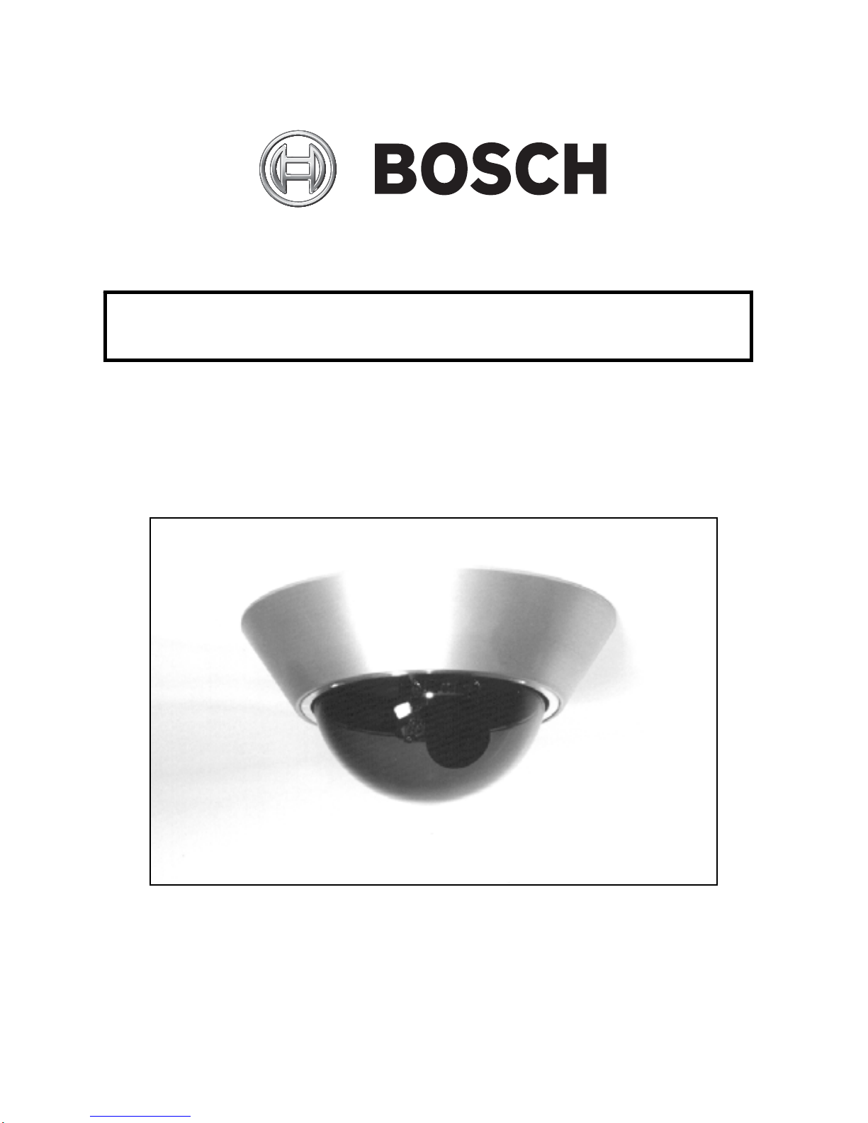
EX49
“No-Grip” High Impact Dome Camera
MAN-49-00
Page 2

IMPORTANT SAFETY INSTRUCTIONS
1. Read these instructions.
2. Keep this instruction.
3. Heed all warnings.
4. Follow all instructions.
5. Do not use this apparatus near water.
6. Clean only with dry cloth.
7. Do not block any ventilation openings. Install
in accordance with manufacturer instructions.
8. Do not install near any heat sources such as
radiators, heat registers, stoves or other
apparatus (including amplifiers) that produce
heat.
9. Do not defeat the safety purpose of the
polarized or grounding-type plug. A polarized
plug has two blades with one wider than the
other. A grounding type plug has two blades
and a third grounding prong. The wide blade
or the third prong is provided for your safety. If
the provided plug does not fit into your outlet,
Page 3

consult an electrician for replacement of the
obsolete outlet.
10. Protect the power cord from being walked on
or pinched particularly at plugs, convenience
receptacles, and the power where they exit
from the apparatus.
11. Only use attachments/accessories specified by
the manufacturer.
12. Use only with the cart, stand, tripod, bracket,
or table specified by the manufacturer, or sold
with the apparatus. When a cart is used, use
caution when moving the cart/apparatus
combination to avoid injury from tip-over.
13. Unplug this apparatus during lightning storms
or when unused for long periods of time.
14. Refer all servicing to qualified service
personnel. Servicing is required when the
apparatus has been damaged in a way, such
as power-supply cord or plug is damaged,
liquid has been spilled or objects have fallen
into the apparatus, the apparatus has been
exposed to rain or moisture, does not operate
normally, or has been dropped.
Page 4
For best results, please read this Instruction Booklet prior to
installing the EX49 camera.
WARNING !
CSA Certified / UL Listed CLASS 2 power adaptors must be used
in order to comply with electrical safety standards.
IMPORTANT
This Product Has Been Certified By CSA International To
Include the Health Care Facility Requirements Of UL 2044.
EU Directives covered by this declaration:
72/9/EC Low Voltage Directives
89/336/EEC Electromagnetic Compatibility Directive
Bosch Security Systems, Inc. will not be responsible for injuries
or damages resulting from the improper installation or use of any
product sold by Bosch Security Systems, Inc their agents,
distributors or dealers.
Page 5

NOTE: This equipment has been tested and found to
comply with the limits for a digital device, pursuant to
part 15 of the FCC rules. These limits are designed to
provide reasonable protection against harmful
interference in a residential installation. As part of its’
normal operation this device can generate radio
frequency energy and if not installed and used in
accordance with the installation manual may cause
interference to radio communications. However, there
is no guarantee that interference will not occur on a
particular installation. If the device does cause
interference to radio or television reception the user is
encouraged to try to correct the interference by one or
more of the following measures:
1) Fit Ferrite beads on all cable to and from the power
supply box, within the box walls.
2) Route the composite cable between the camera and
the power supply in steel conduit piping over the entire
run of the cable up to and including connection to a
deep conduit base fitted under the camera and a conduit
fitting adaptor in the wall of the PSU box.
3) Contact Bosch for further advice.
Page 6

INDEX – EX49
Page
Description .........................................................1
Unpacking ..........................................................2
Parts List ............................................................2
Items Required for Installation ...........................2
Initial Preparations .............................................3
Guidelines ..........................................................3
Section 1. Dome Removal .................................4
Section 2. Input Power Connections................. 6
Section 3. Mounting – Camera Base .................9
Section 4. Lens: Directional, Focus, and
“Auto-Iris” Adjustments....................14
Section 5. Camera Re-Assembly.....................24
Section 6. Troubleshooting Guide....................26
Section 7. Template – Mounting Holes............29
Section 8. General Specifications....................30
Page 7

DESCRIPTION
The EX49 “No-Grip” High Impact Dome
Camera for a Vari Focal “Auto-Iri s” len s has
been engineered for surveillance in hostile
environments. Compact and good looking, the
camera features a smooth “no-grip” housing for
protection against theft and vandalism.
An aluminum housing, CNC-machined from a
billet, with an impact resistant polycarbonate
dome and locking retaining ring, make it
extremely rugged and weather-tight.
For viewing adjustment, the CCD Camera/Lens
Assembly can be fully rotated using a unique
“Pan-Tilt-Twist” (PTT) mo unting bracket.
A voltage regulator circuit allows for 12V dc or
24V ac operation, and a range in between, also
providing protection from voltage surge,
transient spikes, and reverse voltage.
The EX49 is available in several models
designed to meet specific needs.
1
Page 8

UNPACKING
Care should be taken when unpa cking the shipped
unit. Check the parts list and confirm all items have
been located. Inspect the equipment thoroughly to
ensure nothing was damaged in transit.
Contact BOSCH Service Center if a problem is
noted, see the rear page of this booklet for contact
numbers.
PARTS LIST (items supplied with unit)
- EX49 Camera Assembly with foam gasket
- Installation Instructions booklet
- Plastic bag containing one Allen key
ITEMS REQUIRED FOR INSTALLATION
(not su pplied with unit)
- Philips screwdriver
- Small slotted screwdriver
- Mounting screws, etc.
2
Page 9

INITIAL PREPARATIONS
Determine the operating voltage at the
installation site. The camera‘s Voltage
Regulator Board accepts either +12V dc or
24V ac input.
See Section 2, Input Power Connections.
Determine the optimum location for the
camera. Section 3, Mounting-Camera Base.
All cameras have been tested prior to
shipment. After the wiring has been
reconnected, it is advisable to check the
camera’s operation before installation.
ESD protection – Cameras and circuit boards
are sensitive electronic components. It is
recommended to wear a ground strap to
ground any static charge. (Alternative: touch a
grounded metal plate for at least a minute
before proceeding with any disassembly)
GUIDELINES
The installation of the EX49 camera is explained in
Sections 1 to 5 listed below. It is important that these
steps are followed in sequence
1. Dome Removal
2. Input Power Connections
3. Mounting – Camera Base
4. Lens Direction al an d Focus Adjustments
5. Camera Re-Assembly
3
Page 10

1. DOME REMOVAL
The camera dome and its retaining ring must be
removed prior to mounting the camera or
adjusting the lens direction.
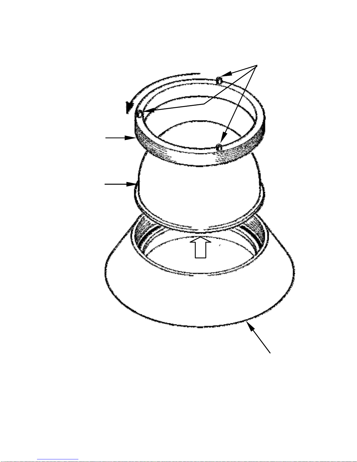
The set-screws in the retaining ring are not
tightened in the factory and protrude by 1/8"
(3mm) in order for the ring to be rotated.
Refer to Figure 1 - 1 on page 5.
Step 1.1 - Place the camera on a flat surface.
Step 1.2 - Press firmly on the dome with one
hand and rotate the retaining ring in
a counter-clockwise direction with
the other hand. Push against the
protruding set-screws with a finger
to rotate the ring. Do not use a
screwdriver or other metal device.
Step 1.3 - Remove the dome and the retaining
ring. Set them aside.
4
Page 11
Retaining
Ring
Dome
Rotation
Set Screws
(3)
FIGURE 1 – 1
Dome Removal
Camera Base
5
Page 12

2. INPUT POWER CONNECTIONS
Attention: External Video Cable Systems Must
Be Properly Grounded In Accordan ce With The
National Electrical Code, ANSI/NFPA 70.
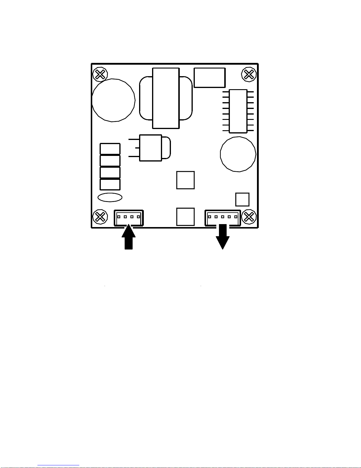
The EX49 Camera Unit is pre-connected with an
electrically isolated power board (VRB) for 24V
ac or 12V dc operation, with no change to the
polarity of the wires.
The VRB also connects to the Camera and to
the Line Lock Board (if available).
See Figure 2 – 1 on page 7.
NOTE:
For DC input, the input voltage range is
10.5V dc to 40V dc.
The recommended input current from the power
supply should be approxim ately 1 Amp.
For AC input, the input voltage range is
12V ac to 28V ac.
The recommended input current from the power
supply should be approxim ately 1 Amp.
6
Page 13
Power
IN
FIGURE 2 – 1
12VDC or 24VAC
Electrically Isolated Power Board
7
Power
OUT
Page 14
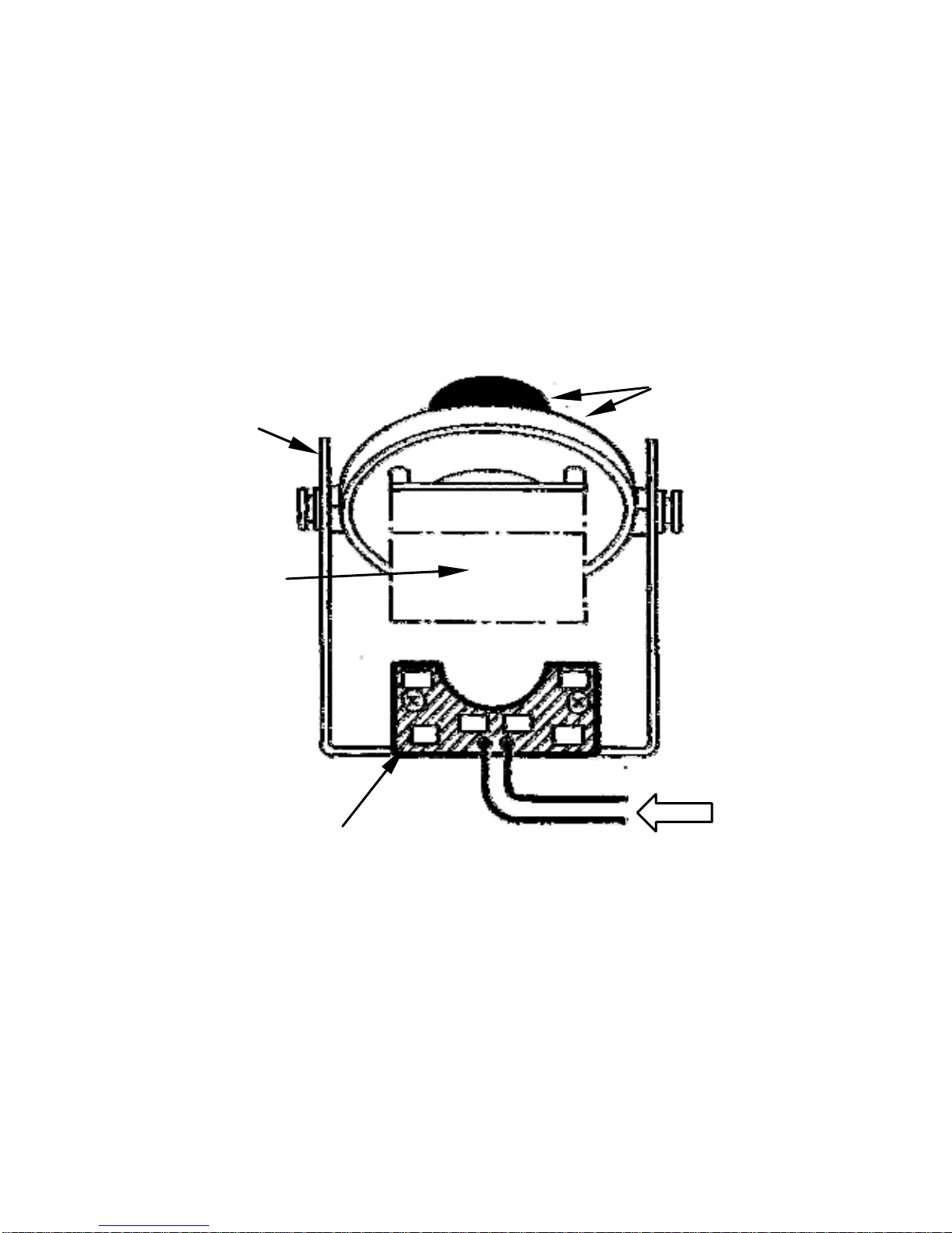
This view shows the location of the optional
Heater Module for the Single Board Fixed Lens
Cameras.
VRB Module
PTT
Mounting
(reference
only, not
exactly as
shown).
Camera and
Single Board
Camera Heater
Terminal Block on VRB Module
Board
FIGURE 2 – 2
Optional Camera Heater for
Single Board Fixed Lens Cameras
From Power Input
8
Page 15

3. MOUNTING - CAMERA BASE
Caution: The selected mounting location should
not place the camera in a situation where its
environmental specifications could be exceeded.
See page 30. Ensure the selected location is
protected from falling objects, accidental contact
with moving objects, and unintentional
interference from personnel. Follow all applicable
building codes.
The following installation guidelines
must be followed:
• Locate the camera such that it cannot be
easily interfered with, either intentionally or
accidentally.
• Select a mounting surface capable of
supporting the combined weight of the
camera and mounting hardware un der all
expected conditions of vibration and
temperature.
• Secure all cabling.
• Installations on drywall must use #8 screws
and #8 drywall nylon plugs or a superior
connection.
9
Page 16

The mounting holes are configured for a single -ga ng
electrical box or a round ceiling electrical box. The
camera base can also be mounted to any flat
surface. See the template on page 29.
It would be advantageous if the power and video
wires from the remote source coul d be routed
into the electrical box at this time.
Step 3.1 - Feed the camera’ s po wer and video
cables through the foam gasket
hole.
Step 3.2 - Connect these cables to the power
and video cables that are routed
from their remote location into the
electrical box.
Step 3.3 - Mount the camera housing to the
electrical box. (Screws are not
supplied).
Refer to Figure 3-1-1, Figure 3-1-2
and Figure 3-1-3 on page 11, 12
and 13.
10
Page 17
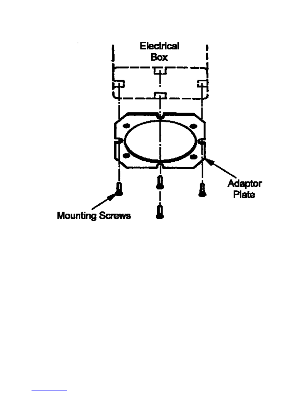
Use four (4) screws for double-gang b oxes or
two (2) screws for ceiling boxes.
FIGURE 3 – 1 – 1
EX47 Camera Adaptor Plate Mounting
11
Page 18
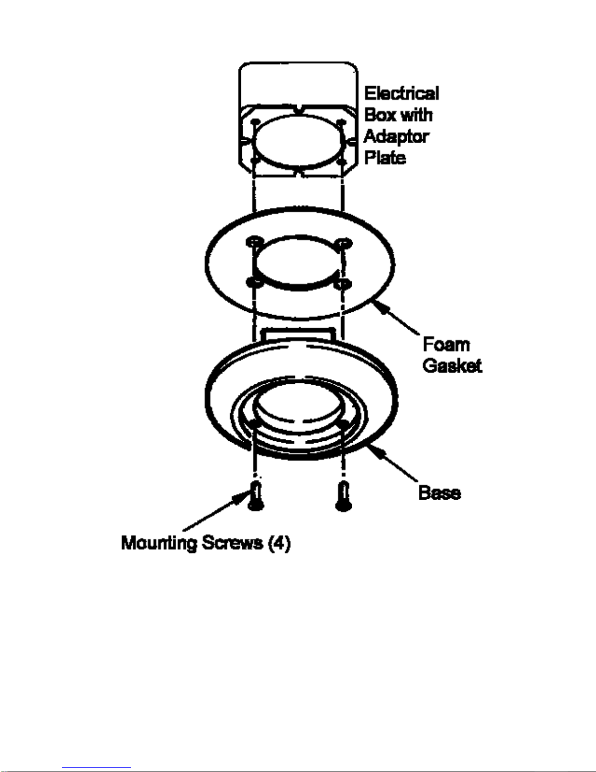
FIGURE 3 – 1 – 2
EX47 Camera Base to Adaptor Plate
Mounting
12
Page 19
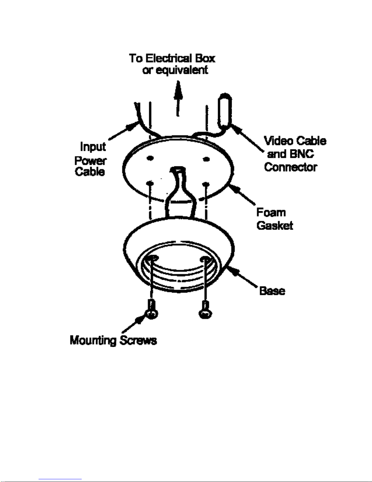
FIGURE 3 – 1 – 3
EX49 Camera Base Mounting
13
Page 20

4. LENS: DIRECTIONAL, FOCUS, and
“AUTO-IRIS” ADJUSTMENTS
For optimum picture quality the camera lens
must be as close as possible to the dome’s
inside face, without touching.
The lens and inside dome clearance a s well as
the camera’s directional adjustment can be
achieved through the use of the PTT adjustment
bracket attached to the housing base.
Refer to Figure 4-2, Figure 4-3, and Figure 4-4
on pages 17, 18, and 19 respectively.
The installer must determine whether th e lens
needs to be adjusted once the came ra’s viewing
angle has been finalized.
For the “Vari Focal” Auto-Iris Lens: Fo cal and
Zoom adjustments are shown in Figure 4-5 on
page 21.
14
Page 21
t
Note:
Gasket Back Cover - Some products have a paper
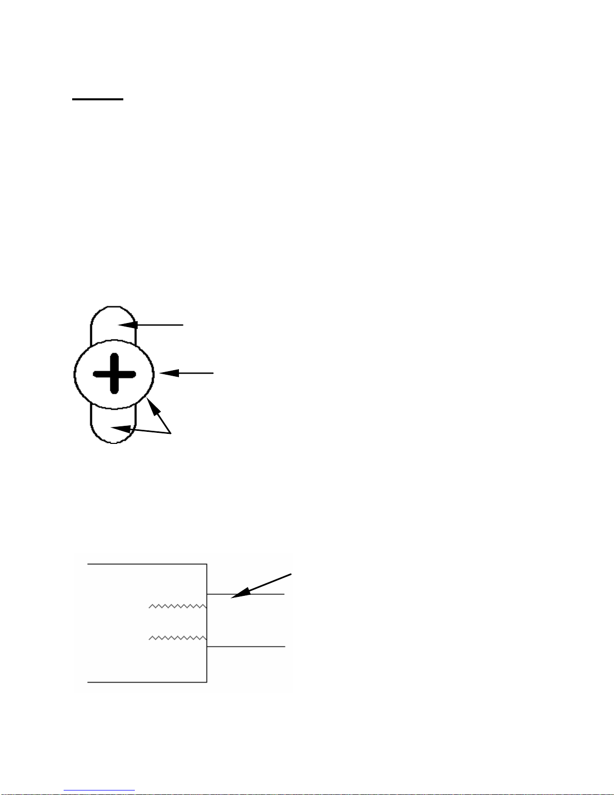
Mounting - It is recommended that the camera be
backing on the gasket. Please remove it before
installation.
mounted to a flat non-porous surface for best
results. The mounting holes and the area around
the mounting screws should be sealed with silicone
to prevent water or moisture from entering into the
unit.
Mounting Hole
Mounting Bol
Seal area around mounting hole
and bolt with silicon
Conduits and Connectors - The conduits and
connectors connecting to the housing should be
sealed with silicone to prevent water and moisture
from entering into the unit.
Seal conduit/connector
Housing
connection with silicone
Conduit/Connector
15
Page 22
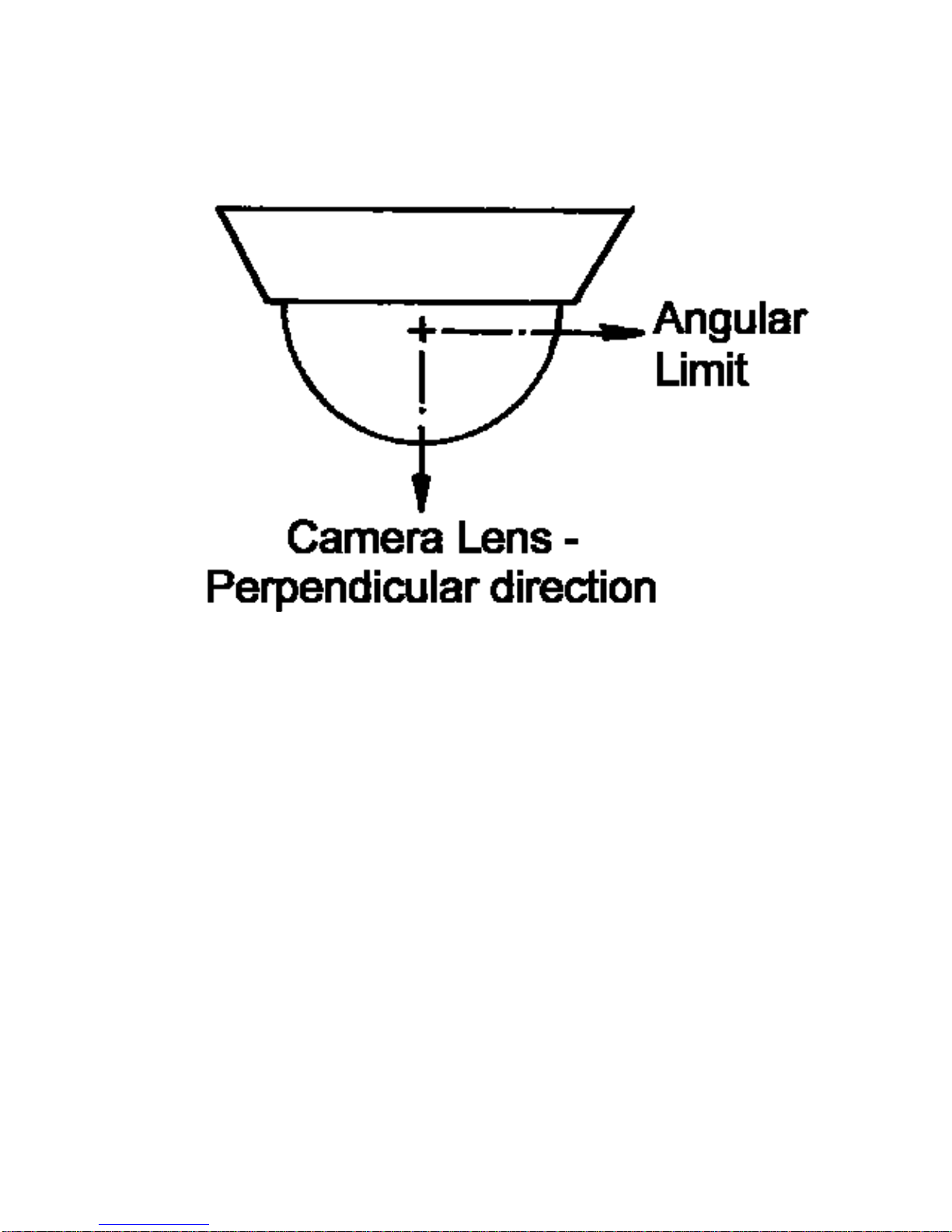
FIGURE 4 – 1
Camera Lens Directional Alignment
16
Page 23
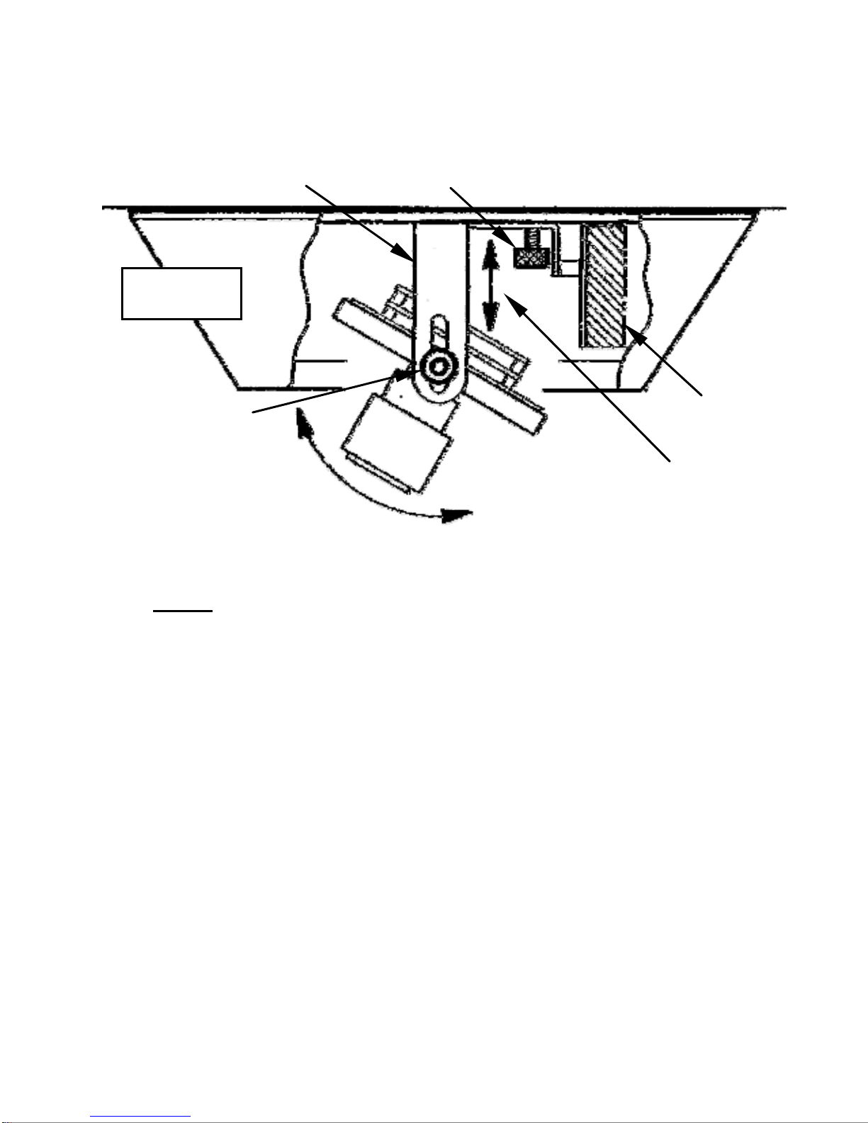
PTT Bracket
Base
Adjustment
Knobs (2)
Tilt Adjustment
PTT Locking Knob
Lens
VRB
Vertical
Adjustment
Note: the optional camera heater board is not
shown for reasons of clarity.
Loosen the two adjustment knobs on the PTT
bracket and tilt the lens to the desired viewing
angle. The adjustment knobs are also used to
position the lens for proximity to the dome. See
Figure 4-3 on page 18 for lens rotational
adjustment.
FIGURE 4 – 2
Directional Adjustment, Tilt and Vertical
17
Page 24
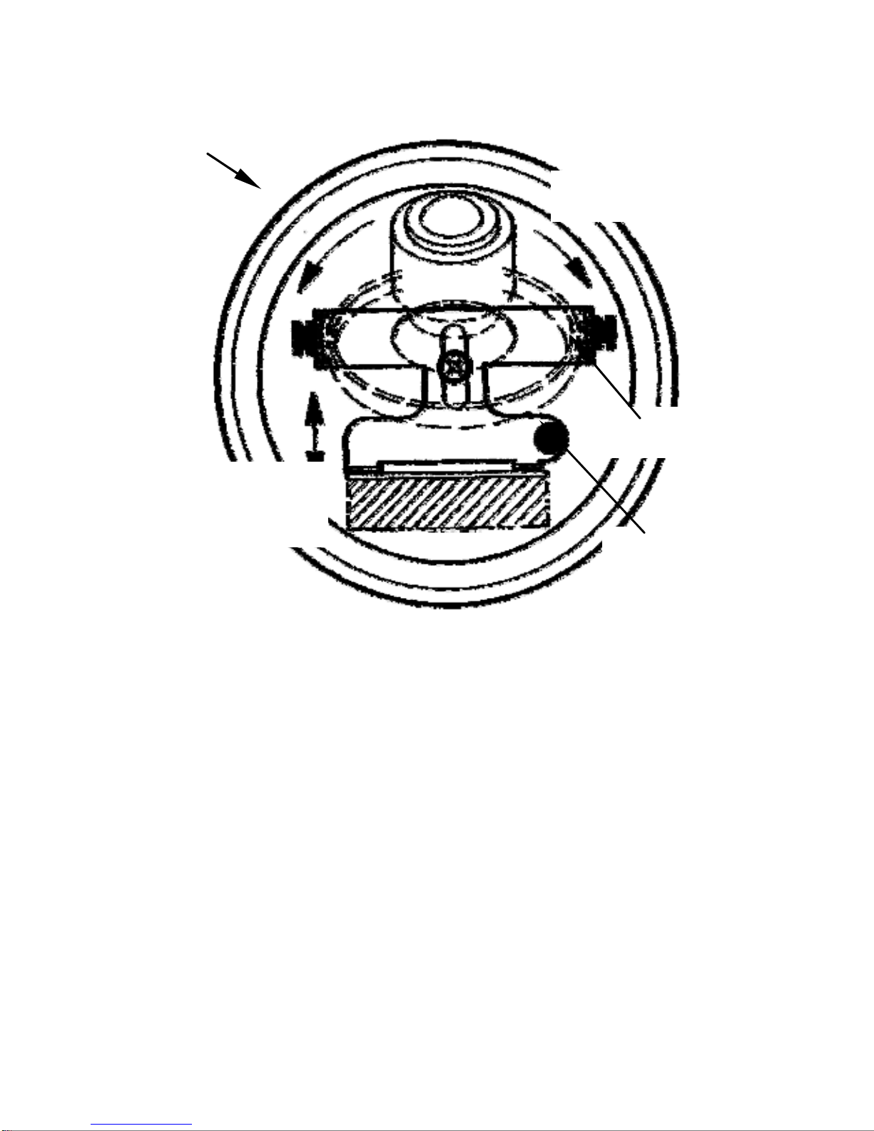
Base
Camera Rotation
PTT Bracket
Linear
Adjustment
Locking
Knob
Loosen the locking knob, rotate the PTT and
Camera/Lens assembly to the desired position,
and re-tighten the knob. The Camera Assembly
can also be moved along the linear axis by this
method. The complete directional adjustment
must be done in conjunction with Figure 4-2 on
page 17.
FIGURE 4 – 3
Directional Adjustment, Rotation
18
Page 25
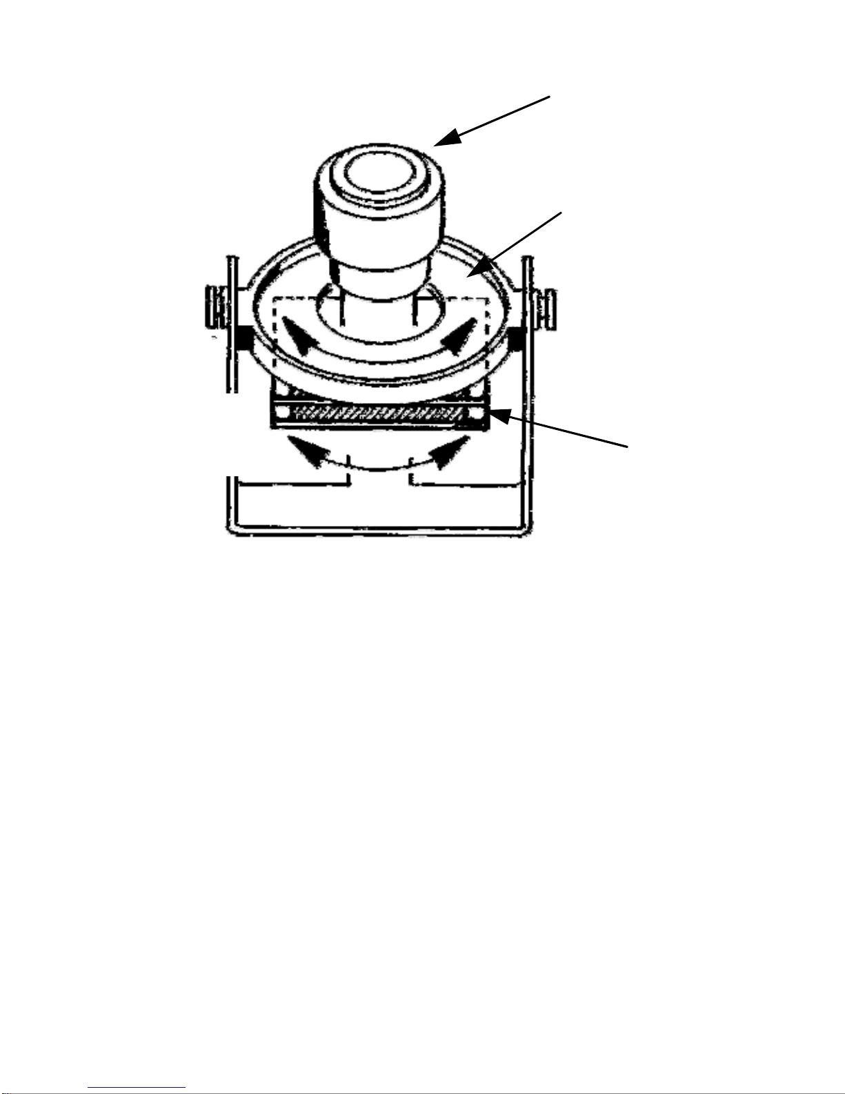
Camera Lens.
Adjustable Disc
for rotation
Disc
Rotation
Camera
Boards
(dual)
This adjustment is necessary in case the
image on the monitor is not perpendicular.
DO NOT touch the camera lens during this
adjustment.
Grip the camera boards between thumb
and finger. Rotate the disc until the
image is correctly shown on a monitor.
FIGURE 4 – 4
Camera Twist Adjustment
19
Page 26

4.1 Vari Focal and “Auto-Iris” Control
Adjustments
Step 4.1.1 - Loosen the lens set-screws
For focus/zoom adjustments.
See Figure 4-5 on page 21.
Step 4.1.2 - The set screw marked N ←→ ∞
is used for image focus.
Step 4.1.3 - The set screw marked T←→ W
is used for telephoto or wideangle settings.
Step 4.1.4 - Re-tighten the set screws after
focus adjustments have been
completed.
Step 4.1.5 - Locate the “Auto-Iris”
adjustment controls.
Step 4.1.6 - Adjust the “Auto-Iris”
20
Page 27
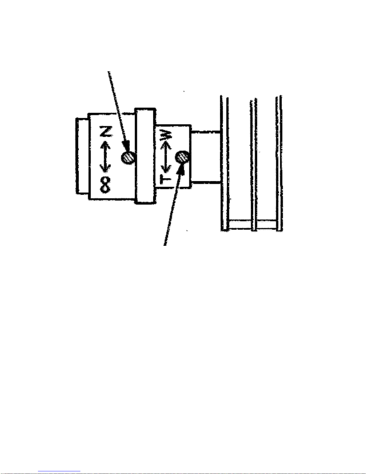
j
Loosen this set screw
for Focus ad
ustment.
Loosen this set screw for
Telephoto (T) or Wide
Angle (W) adjustment.
FIGURE 4-5
Lens Focus Adjustment
21
Page 28

Vari Focal Lens Adjustments
• Loosen the lens set screws for focus/zoom
adjustments.
• The setscrew marked N ←→ ∞ is used for
image focus.
• The setscrew marked T←→ W is used for
telephoto or wide-angle settings.
• Re-tighten the setscrews after focus
adjustments have been completed.
22
Page 29

Use a Neutral Density filter or Infra-Red Pass filter to cover
the lens during focusing to simulate low light conditio ns on
scene for correct 24-hour focusing. For camera with varifocal lens, the camera should be focused with the lens ir is
fully opened to simulate the worst possible depth of field.
Using a Neutral Density filter or Infra-Red Pass filter will
ensure the iris is fully open for correct setup and
adjustment.
Note that statement above is applicable only for Day/Night
or IR version cameras.
23
Page 30

5. CAMERA RE-ASSEMBLY
Make sure all wires are properly connected and
tightened into the terminal blocks, all holes are
sealed against moisture penetration, an d all
mounting screws are tight.
Step 5.1 - Check that the large “O” ri ng gasket
in the camera base has not been
dislodged or distorted.
Step 5.2 - Gently press the camera dome in
place. Move the retaining ring over
the dome.
Step 5.3 - Use the protruding set-screws in the
retaining ring to carefully rotate the
ring clockwise until it is slightly snug,
but not so tight that the ring cannot
rotate further.
Step 5.4 - Press firmly on the dome and rotate
the retaining ring until one of the
set-screws aligns with the
adhesive dot on the side of the
dome. Tighten all set-screws with
the supplied Allen key. Refer to
Figure 5-1 on page 25.
24
Page 31
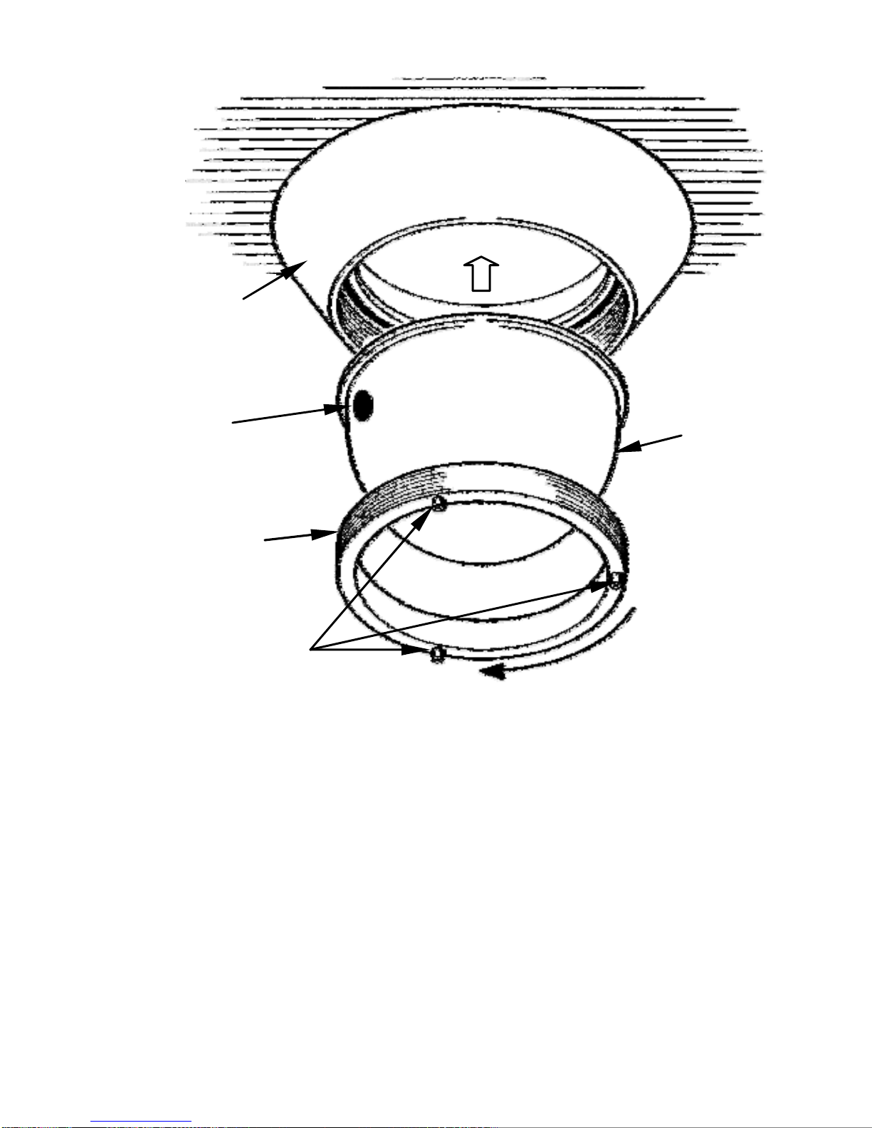
Camera
Base
Adhesive
Dot
Retaining
Ring
Set Screws
Tighten
FIGURE 5 – 1
Camera Re-Assembly
The Camera/Lens and PTT Assemblies are not
Dome
shown for clarity purposes.
25
Page 32

6. TROUBLESHOOTING GUIDE
PROBLEM POSSIBLE
CAUSE
No Video 1. Power Supply:
-Connections….
-Voltage Range...
LIKELY SOLUTION
Check input power
connections at the
cable leads.
Check for loose wires.
If connected to DC,
check input voltage
range of 10.5 – 40V.
If connected to AC,
check input voltage
range of 12 – 28V.
Measure the voltage
and current at the
Input Power Cable.
The current should be
>.02A and <1.0A.
26
Page 33

No Video
2. Video
(cont’d.)
Connections
Determine if wiring
polarity at “Video
Connector” terminal
block is correct.
Check the cable and
BNC connector.
If still no video,
connect the camera
directly to the
monitor. Check the
video signal. If okay,
the problem is with
the interconnections.
If still no video,
contact BOSCH
__________
Poor
Picture
Snowy
Image
________________
Poor Video Signal
Service Center. See
rear page of this
manual for contact
information
_________________
Ensure the video
cable is correctly
matched and
terminated with 75
ohms at each end.
Make sure the video
cables are similar
types.
27
Page 34

Poor
Picture
Snowy
Image
(cont’d.)
Horizontal
Scan Lines,
Rolling Up
or Down
Negative,
scrambled,
or faded
Noisy Power
Supply
Ground Looping on
video cable
Low voltage
Check connections.
Relocate or replace
the power supply.
Check the coax cable
shield is not touching
ground, e.g. at
couplings.
Check video polarity.
Check voltage at the
input power cable.
Must be >10.5V dc or
image
>12V ac.
28
Page 35

7. MOUNTING HOLE DIAGRAM
29
Page 36

8. GENERAL SPECIFICATIONS
TV System......Color – NTSC (PAL optional)
Monochrome – EIA (CCIR optional)
Video Signal Output............1 V p-p, 75 Ohm
Operational Range................-50°C to +50°C
*with optional heater............. -70°C to +50°C
Humidity Range.............Up to 85% (relative)
Power Supply (dc) .............12V dc or 24V ac
............................................................... 10W
Dome......................................Polycarbonate
Base & Retaining Ring .........CNC Aluminum
Anodized
Dimensions.......................7” (177.8mm) dia.
3.56” (91mm) ht.
Weight.....................................1.5 lbs. (680g)
Subject To Change Without Notice.
30
Page 37

NOTE:
Page 38

NOTE:
Page 39

Americas
Bosch Security Systems, Inc.
850 Greenfield Road
Lancaster, Pennsylv ania 17601
USA
Telephone+1 888-289-0096
Fax +1 585-223-9180
Email: [email protected]
www.boschsecurity.us
© Bosch Security Systems, Inc. 2009; Data subject to change
without notice.
Europe, Middle East, Africa:
Bosch Security Systems B.V.
P.O. Box 80002
5600 JB Eindhoven,
The Netherlands
Phone: + 31 40 2577 284
Fax: +31 40 2577 330
[email protected]
www.boschsecurity.com
Asia-Pacific:
Bosch Security Systems Pte Ltd
38C Jalan Pemimpin
Singapore 577180
Phone: +65 6319 3450
Fax: +65 6 319 3499
[email protected]
www.boschsecurity.com
 Loading...