

Bosch ET80-24MCW-FW, ET80-24MCW-FR Installation Manual
.
273 Branchport Avenue Thank you for using our products.
Long Branch, NJ 07740
(800) 631-2148 INSTALLATION INSTRUCTIONS
www.wheelockinc.com
ET80 VANDAL RESISTANT SPEAKER AND STROBE SPEAKERS
Use this product according to this instruction manual. Please keep this instruction manual for future reference.
GENERAL:
Wheelock’s Series ET80 Low Profile Vandal Resistant Speaker and Speaker Strobes are UL Listed under Standard 1971 for
(Signaling Devices for the Hearing Impaired) for indoor fire protection service. The ET80-24MCW is designed for multiple power
requirements with high dBA output at each power tap and offer a choice of field selectable taps, 1/8W to 8W for either 25.0VRMS or
70.0VRMS audio systems. The Low Profile design incorporates a high efficiency speaker for maximum output at minimum power
across a frequency range of 400Hz to 4000Hz, and features a sealed back construction for extra protection and improved audibility.
The ET80-24MCW Multi-Candela provides four selectable light output intensities in one unit and incorporates a Speaker Mounting
Plate attached to the speaker for ease of installation. The Low Profile Speaker Strobe can provide a non-synchronized strobe
appliance when connected directly to a Fire Alarm Control Panel (FACP), or provide a synchronized strobe appliance when used in
conjunction with a Sync Module (SM), Dual Sync Module (DSM) or Wheelock’s Power Supplies. The Strobe uses a Xenon
flashtube with solid state circuitry enclosed in a rugged Lexan lens to provide maximum visibility and reliability for effective visible
signaling. The ET80-24MCW is Listed for indoor use, wall mount only
with the backboxes specified in these instructions (see
Mounting Options).
NOTE: “Lexan” is a registered trademark of General Electric Company.
NOTE: All CAUTIONS and WARNINGS are identified by the symbol . All warnings are printed in bold capital letters.
WARNING: THE SPEAKER STROBE APPLIANCE IS A "FIRE ALARM DEVICE - DO NOT PAINT."
WARNING: PLEASE READ THESE INSTRUCTIONS CAREFULLY. FAILURE TO COMPLY WITH ANY OF THE
FOLLOWING INSTRUCTIONS, CAUTIONS AND WARNINGS COULD RESULT IN IMPROPER APPLICATION,
CANDELA SETTING, INSTALLATION AND/OR OPERATION OF THESE PRODUCTS IN AN EMERGENCY
SITUATION, WHICH COULD RESULT IN PROPERTY DAMAGE AND SERIOUS INJURY OR DEATH TO YOU
AND/OR OTHERS.
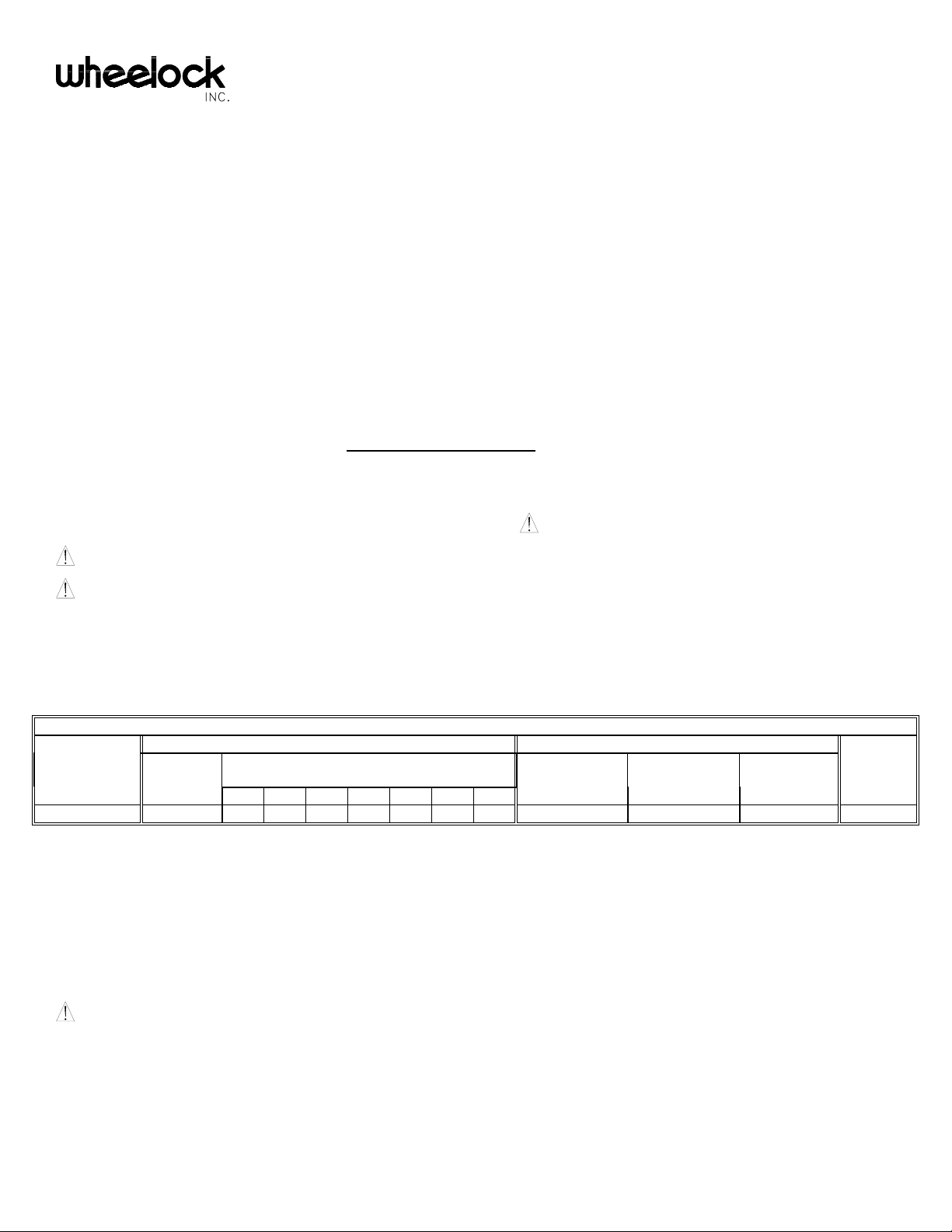
SPECIFICATIONS:
Table 1: UL Listed Models and Ratings
Speaker Strobe
Models Voltage Candela Mounting
(VRMS)
1/8 1/4 1/2 1 2 4 8 (VDC/VRMS) (VDC/VRMS)
ET80-24MCW 25/70 78 81 84 87 90 92 94 24 16.0-33.0 15/30/75/110 A,B
dBA at 10 Feet
(Rated Watts)
Regulated
Voltage
Voltage
Range Options
NOTES:
1. The strobe will produce 1 flash per second over the "Regulated Voltage" range.
2. The ET80-24MCW is UL Listed for indoor use with a temperature range of +32°F to +120°F (0°C to +49°C) and maximum
humidity of 85% RH.
NOTE: THE MAXIMUM WIRE IMPEDENCE BETWEEN STROBES SHALL NOT EXCEED 35 OHMS. THE
MAXIMUM NUMBER OF STROBES ON A SINGLE NOTIFICATION APPLIANCE CIRCUIT SHALL NOT EXCEED 47.
WARNING: FOR UL APPLICATIONS THESE APPLIANCES WERE TESTED TO THE OPERATING VOLTAGE
LIMITS OF 16-33 VOLTS USING FILTERED (DC) OR UNFILTERED FULL-WAVE-RECTIFIED (FWR). DO NOT
APPLY 80% AND 110% OF THESE VOLTAGE VALUES FOR SYSTEM OPERATION.
Copyright 2004 Wheelock, Inc. All rights reserved.
P84506 B
Sheet 1 of 8
WARNING: CHECK THE MINIMUM AND MAXIMUM OUTPUT OF THE POWER SUPPLY AND STANDBY
BATTERY AND SUBTRACT THE VOLTAGE DROP FROM THE CIRCUIT WIRING RESISTANCE TO DETERMINE
THE APPLIED VOLTAGE TO THE STROBES.
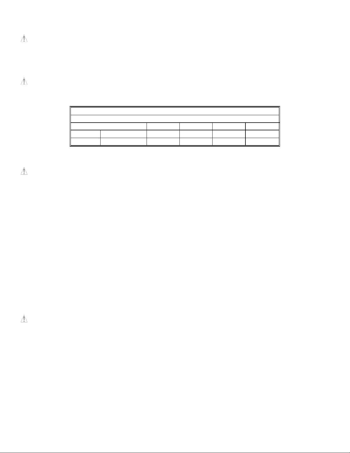
WARNING: CANDELA SETTING WILL DETERMINE THE CURRENT DRAW OF THE PRODUCT.
Table 2: UL Current Ratings
Maximum RMS Current Draw
UL Voltage 15cd 30cd 75cd 110cd
DC 16-33VDC 0.060 0.092 0.165 0.220
FWR 16-33VRMS 0.102 0.155 0.253 0.347
WARNING: MAKE SURE THAT THE TOTAL RMS CURRENT REQUIRED BY ALL APPLIANCES THAT ARE
CONNECTED TO THE SYSTEM’S PRIMARY AND SECONDARY POWER SOURCES, NAC CIRCUITS, SM, DSM SYNC
MODULES OR WHEELOCKS POWER SUPPLIES DO NOT EXCEED THE POWER SOURCES’ RATED CAPACITY OR THE
CURRENT RATINGS OF ANY FUSES ON THE CIRCUITS TO WHICH THESE APPLIANCES ARE WIRED. OVERLOADING
POWER SOURCES OR EXCEEDING FUSE RATINGS COULD RESULT IN LOSS OF POWER AND FAILURE TO ALERT
OCCUPANTS DURING AN EMERGENCY, WHICH COULD RESULT IN PROPERTY DAMAGE AND SERIOUS INJURY OR
DEATH TO YOU AND/OR OTHERS.
When calculating the total currents: Use Table 2 to determine the highest value of “RMS Current” for an individual strobe (across the
expected operating voltage range of the strobe), then multiply these values by the total number of strobes; be sure to add the currents
for any other appliances, including audible signaling appliances, powered by the same source and include any required safety factors.
If the peak current exceeds the power supplies’ peak capacity, the output voltage provided by the power supplies may drop below the
listed voltage range of the appliances connected to the supply and the voltage may not recover in some types of power supplies. For
example, an auxiliary power supply that lacks filtering at its output stage (either via lack of capacitance and/or lack of battery backup
across the output) may exhibit this characteristic.
CAUTION: The Speaker Strobe is not designed to be used on coded systems in which the applied voltage is cycled on and off.
P84506 B
Sheet 2 of 8
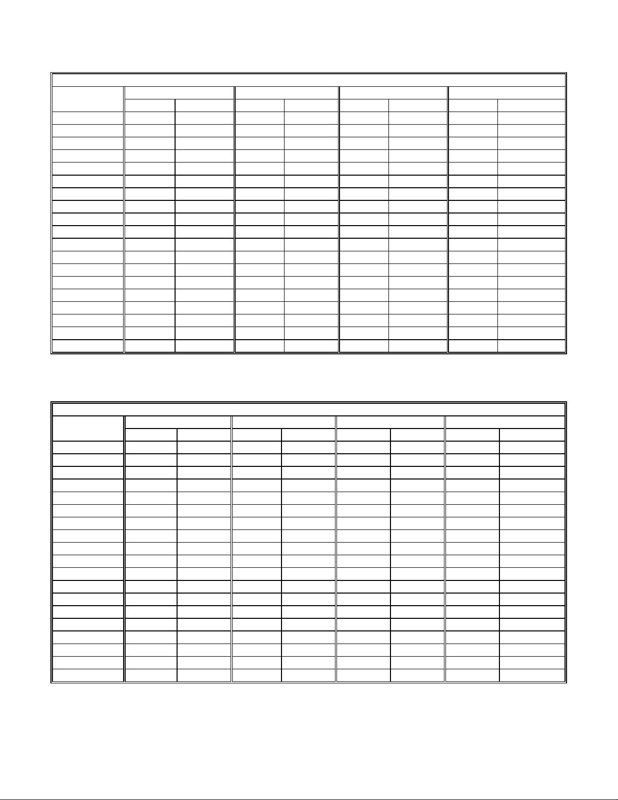
LIGHT DISTRIBUTION:
Table 3A: Horizontal Plane
Horizontal 15cd 30cd 75cd 110cd
Angle (in deg.) UL Min. Typ. 15cd UL Min. Typ. 30cd UL Min. Typ. 75cd UL Min. Typ. 110cd
0 15.0 22 30.0 44 75.0 110 110.0 158
5 13.5 22 27.0 42 67.5 114 99.0 162
10 13.5 23 27.0 42 67.5 110 99.0 156
15 13.5 22 27.0 41 67.5 110 99.0 153
20 13.5 21 27.0 40 67.5 108 99.0 153
25 13.5 20 27.0 38 67.5 102 99.0 139
30 11.3 20 22.5 38 56.3 103 82.5 142
35 11.3 18 22.5 36 56.3 97 82.5 135
40 11.3 18 22.5 35 56.3 93 82.5 130
45 11.3 20 22.5 39 56.3 103 82.5 143
50 8.3 19 16.5 37 41.3 93 60.5 133
55 6.8 14 13.5 27 33.8 71 49.5 98
60 6.0 15 12.0 30 30.0 73 44.0 102
65 5.3 15 10.5 28 26.3 71 38.5 97
70 5.3 14 10.5 25 26.3 64 38.5 88
75 4.5 12 9.0 23 22.5 54 33.0 76
80 4.5 10 9.0 17 22.5 47 33.0 64
85 3.8 5 7.5 10 18.8 25 27.5 33
90 3.8 7 7.5 15 18.8 39 27.5 52
Table 3B: Vertical Plane
Vertical 15cd 30cd 75cd 110cd
Angle (in deg.) UL Min. Typ. 15cd UL Min. Typ. 30cd UL Min. Typ. 75cd UL Min. Typ. 110cd
0 15.0 23 30.0 45 75.0 113 110.0 160
5 13.5 24 27.0 48 67.5 119 99.0 166
10 13.5 21 27.0 39 67.5 101 99.0 143
15 13.5 19 27.0 39 67.5 102 99.0 136
20 13.5 19 27.0 37 67.5 98 99.0 122
25 13.5 18 27.0 35 67.5 88 99.0 122
30 13.5 15 27.0 31 67.5 80 99.0 106
35 9.8 17 19.5 31 48.8 84 71.5 112
40 6.9 13 13.8 24 34.5 62 50.6 86
45 5.1 7 10.2 12 25.5 33 37.4 44
50 4.1 6 8.1 11 20.3 29 29.7 41
55 3.3 6 6.6 11 16.5 28 24.2 38
60 2.7 5 5.4 10 13.5 27 19.8 37
65 2.4 5 4.8 10 12.0 27 17.6 37
70 2.3 6 4.5 10 11.3 27 16.5 37
75 2.0 5 3.9 10 9.8 26 14.3 36
80 1.8 5 3.6 9 9.0 25 13.2 33
85 1.8 5 3.6 9 9.0 24 13.2 33
90 1.8 2 3.6 5 9.0 12 13.2 17
P84506 B
Sheet 3 of 8
 Loading...