

Bosch ES 100 5, ES 120 5, ES 150 5, ES 035 5, ES 050 5 Installation And Operating Instructions Manual
...
Installation and operating instructions
DHW cylinder
Tronic 4000 T | Tronic 6000 T
6720818520-00.1V
ES 035/050/080/100/120/150 5 ...
6 720 818 731 (2016/07) EN

6 720 818 731 (2016/07) Tronic 4000 T | Tronic 6000 T
2 | Table of Contents
Table of Contents
1 Explanation of symbols and safety instructions . . . 3
1.1 Explanation of symbols . . . . . . . . . . . . . . . . . 3
1.2 Safety instructions . . . . . . . . . . . . . . . . . . . . 3
2 Technical properties and dimension's . . . . . . . . . . . 4
2.1 Determined use . . . . . . . . . . . . . . . . . . . . . . . 4
2.2 Type overview . . . . . . . . . . . . . . . . . . . . . . . . 4
2.3 Description of the DHW cylinder . . . . . . . . . 4
2.4 Corrosion protection . . . . . . . . . . . . . . . . . . . 4
2.5 accessories . . . . . . . . . . . . . . . . . . . . . . . . . . 4
2.6 Technical data . . . . . . . . . . . . . . . . . . . . . . . . 5
2.7 Dimensions . . . . . . . . . . . . . . . . . . . . . . . . . . 6
2.8 Appliance layout . . . . . . . . . . . . . . . . . . . . . . 7
2.9 Wiring diagram . . . . . . . . . . . . . . . . . . . . . . . 7
3 Regulations . . . . . . . . . . . . . . . . . . . . . . . . . . . . . . . . . . 7
4 Transport . . . . . . . . . . . . . . . . . . . . . . . . . . . . . . . . . . . 7
4.1 Transportation, storage and recycling . . . . . 7
5 Installation . . . . . . . . . . . . . . . . . . . . . . . . . . . . . . . . . . 7
5.1 Important information . . . . . . . . . . . . . . . . . . 7
5.2 Selecting the installation location . . . . . . . . 8
5.3 Wall mounting bracket . . . . . . . . . . . . . . . . . 8
5.4 Water connection . . . . . . . . . . . . . . . . . . . . . 9
5.5 Electrical connection . . . . . . . . . . . . . . . . . . 10
5.6 Commissioning . . . . . . . . . . . . . . . . . . . . . . 10
6 Operating the appliance . . . . . . . . . . . . . . . . . . . . . . 10
6.1 Turn the appliance on/off . . . . . . . . . . . . . . 10
6.2 Adjust the domestic hot water
temperature . . . . . . . . . . . . . . . . . . . . . . . . 11
6.3 Draining the DHW cylinder . . . . . . . . . . . . . 11
7 Environmental protection/Recycling . . . . . . . . . . . 12
8 Maintenance/inspection . . . . . . . . . . . . . . . . . . . . . 12
8.1 User information . . . . . . . . . . . . . . . . . . . . . 12
8.1.1 Cleaning . . . . . . . . . . . . . . . . . . . . . . . . . . . . 12
8.1.2 Checking the pressure relief valve . . . . . . . 12
8.1.3 Pressure relief valve . . . . . . . . . . . . . . . . . . 12
8.1.4 Maintenance and repair . . . . . . . . . . . . . . . 12
8.2 Regular maintenance . . . . . . . . . . . . . . . . . 12
8.2.1 Function check . . . . . . . . . . . . . . . . . . . . . . 13
8.2.2 Magnesium anode . . . . . . . . . . . . . . . . . . . . 13
8.2.3 Regular thermal disinfection . . . . . . . . . . . 13
8.2.4 Extended nonuse (longer than 3 months) . 13
8.3 Safety Thermostat . . . . . . . . . . . . . . . . . . . . 14
8.4 After maintenance . . . . . . . . . . . . . . . . . . . . 14
9 Faults . . . . . . . . . . . . . . . . . . . . . . . . . . . . . . . . . . . . . . 15
9.1 Fault/cause/remedy . . . . . . . . . . . . . . . . . . 15
6 720 818 731 (2016/07)Tronic 4000 T | Tronic 6000 T
Explanation of symbols and safety instructions | 3
1 Explanation of symbols and safety
instructions
1.1 Explanation of symbols
Warnings
The following signal words are defined and can be used in this
document:
• NOTICE indicates that material damage may occur.
• CAUTION indicates that minor to medium personal injury
may occur.
• WARNING indicates that severe or life-threatening
personal injury may occur.
• DANGER indicates that severe to life-threatening personal
injury will occur.
Important information
Additional symbols
1.2 Safety instructions
Installation
▶ Installation must only be carried out by an authorised
contractor.
▶ If applicable, the installation of the DHW cylinder and/or
the electrical accessories must satisfy IEC 60364-7-701.
▶ Install the DHW cylinder in a room free from the risk of frost.
▶ Before making the electoral connections, make the
hydraulic connections first and check for tightness.
▶ Before installation, disconnect the DHW cylinder from the
power supply.
Installation and conversion
▶ Only permit an authorised contractor to install or convert
this DHW cylinder.
▶ Never plug the drain of the pressure relief valve.
▶ Water may escape from the pressure relief valve drain
when it is being heated.
Maintenance
▶ Only authorised contractors are permitted to maintain this
appliance.
▶ Isolate the appliance from its power supply before
commencing any maintenance work on the DHW cylinder.
▶ The user is responsible for safety and environmental
compatibility during installation and service work.
▶ Use only original spare parts.
▶ If the power cable is damaged, it may only be replaced by
the manufacturer, the manufacturer's customer service, or
individuals who are comparably qualified in order to
prevent danger.
Handover to the user
When handing over the heating system, instruct the user in its
operation and operating conditions.
▶ Explain the operation - with particular emphasis on all
safety-related actions.
▶ Explain that conversions and repairs must only be carried
out by an approved contractor.
▶ Point out the need for inspections and maintenance for
safe and environmentally-compatible operation.
▶ The installation and operating instructions must be given to
the user for safekeeping.
Safety of electrical devices for domestic
use and similar purposes
The following requirements apply in
accordance with EN 60335-1 in order to
prevent hazards from occurring when using
electrical appliances:
“This appliance can be used by children of 8
years and older, as well as by people with
reduced physical, sensory or mental
capabilities or lacking in experience and
knowledge, if they are supervised and have
been given instruction in the safe use of the
appliance and understand the resulting
dangers. Children shall not play with the
Warnings in the text are indicated by a warning
triangle.
In addition, signal words are used to indicate
the type and seriousness of the ensuing risk if
measures for minimising the danger are not
taken.
Important information where there is no danger
to people or property is indicated with the
adjacent symbol.
Symbol Meaning
▶Action step
Cross-reference to another part of the document
• List/list entry
– List/list entry (second level)
Table 1
6 720 818 731 (2016/07) Tronic 4000 T | Tronic 6000 T
4 | Technical properties and dimension's
appliance. Cleaning and user maintenance
shall not be made by children without
supervision.”
“If the power cable is damaged, it must be
replaced by the manufacturer, its customer
service department or a similarly qualified
person, so that risks are avoided.”
2 Technical properties and dimension's
2.1 Determined use
DHW cylinders are designed for heating and storing potable
water. Please observe national, regional, and local codes,
regulations, guidelines and standards for potable water.
Any other use is considered inappropriate. We take no
responsibility for damage caused through incorrect use.
The service life of the device strongly depends on using water
with appropriate properties.
2.2 Type overview
[ES] Electrical domestic hot water cylinder
[035] Cylinder capacity (liters)
[5] Version
[1200 W] Performance
[BO] Make
[H1, M1] Design
[X] Standard diameter
[C] Capillary temperature controller
[T] Thermometers
[W] Wall-mounted installation
[V] Vertical installation
[R] Reversible installation
[B] Connections to the bottom side
2.3 Description of the DHW cylinder
• Enamel-coated steel storage cylinder according to
European standards
• High pressure stability
• Outer wall jacket: Sheet-metal and/or plastic
• Easy operation
• CFC-free PU insulation
• Magnesium anode
2.4 Corrosion protection
The internal wall of the DHW cylinder is enamel-coated. This
provides fully neutral and water-compatible contact with
possible water. As an additional corrosion protection measure,
a magnesium anode is installed.
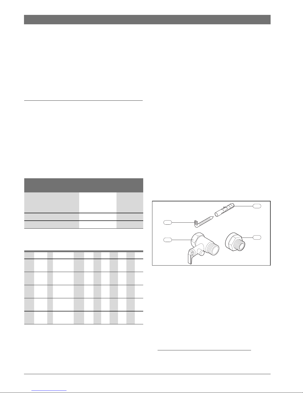
2.5 accessories
Fig. 1
[1] Screws (2x)
1)
[2] Rawl plug (2x)
1)
[3] Pressure relief valve (8 bar)
1)
[4] Isolation fitting (2x)
1)
Requirements for
potable water
Units
Water hardness, min. ppm
grain/US gallon
°dH
120
7.2
6.7
pH, min. – max. 6.5 – 9.5
Conductivity, min. – max. μS/cm 130 – 1500
Table 2 Requirements for potable water
ES 035 5 1200 W BO H1 XCTWVB
ES 050 5 1600 W
1500 W
BO H1M1XCTWRVB
ES 080 5 2000 W BO H1M1XCTWRVB
ES 100 5 2000 W BO H1M1XCTWRVB
ES 120 5 2000 W BO H1M1XCTWRVB
ES 150 5 2400 W
2000 W
BO H1M1XCTWRVB
Table 3
1) Only some models
6720801526-01.2V
3
1
2
4
6 720 818 731 (2016/07)Tronic 4000 T | Tronic 6000 T
Technical properties and dimension's | 5
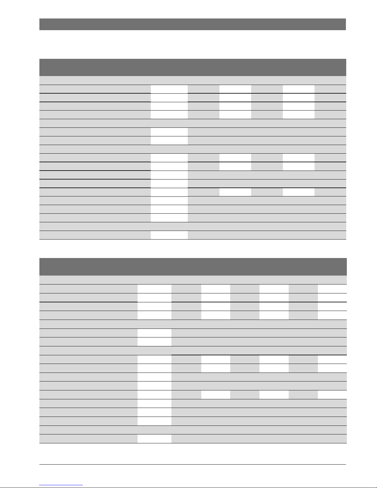
2.6 Technical data
This appliance meets the requirements specified by the European Directives 2014/35/EC and 2014/30/EC.
Tronic 4000 T
Technical data Units ES 050 ES 080 ES 100 ES 120 ES 150
General Information
Capacity l 48 77 95 115 143
Dry weight kg 18,8 22,5 25,8 29,3 35
Weight when full kg 66,8 99,5 120,8 144,3 178
Standing loss kW/24h 0,73 0,91 1,03 1,28 1,43
Water data
Max. permissible operating pressure bar 8
Water connections inch 1/2
Electrical data
Rated output W 1500 2000 2000 2000 2000
Heat-up time (T- 50 °C) 1 h 52 min 2 h 14 min 2 h 47 min 3 h 22 min 4 h 09 min
Supply voltage VAC 230
Frequency Hz 50
Electrical current (single phase) A 6,5 8,7 8,7 8,7 8,7
Power cable with plug (type) HO5VV - F 3 x 1,5 mm2 or HO5VV - F 3 x 1,0 mm
2
Protection class I
IP-Rating IP24
DHW temperature
Temperature range °C up to 70 °C
Table 4 Technical data
Tronic 6000 T
Technical data Units ES 035 ES 050 ES 080 ES 100 ES 120 ES 150
General Information
Capacity l 34 47 76 95 115 142
Dry weight kg 15,7 19,2 22,5 25,8 29,3 35
Weight when full kg 49,7 66,2 98,5 120,8 144,3 177
Standing loss kW/24h 0,78 0,73 0,91 1,03 1,28 1,43
Water data
Max. permissible operating pressure bar 8
Water connections inch 1/2
Electrical data
Rated output W 1200 1600 2000 2000 2000 2400
Heat-up time (T- 50 °C) 1 h 40 min 1 h 44 min 2 h 14 min 2 h 46 min 3 h 21 min 3 h 27 min
Supply voltage VAC 230
Frequency Hz 50
Electrical current (single phase) A 5,2 6,9 8,7 8,7 8,7 10,4
Power cable with plug (type) HO5VV - F 3 x 1,5 mm2 or HO5VV - F 3 x 1,0 mm
2
Protection class I
IP-Rating IP24
DHW temperature
Temperature range °C up to 70 °C
Table 5 Technical data

6 720 818 731 (2016/07) Tronic 4000 T | Tronic 6000 T
6 | Technical properties and dimension's
2.7 Dimensions
Fig. 2 Dimensions in mm (vertical installation)
Fig. 3 Dimensions in mm (horizontal installation)
A
185
ØG1/2''
27.5
C
Ø470
486
100
B
6720818520-01.1V
min. 220
max. 300
D
>250
>500
6720818520-02.1V
Device A B C D
ES035... 485 300 405 ----ES050... 585 400 505 180
ES080... 810 625 730 407
ES100... 960 775 880 552
ES120... 1110 925 1030 702
ES150... 1329 1144 1250 927
Table 6

6 720 818 731 (2016/07)Tronic 4000 T | Tronic 6000 T
Regulations | 7
2.8 Appliance layout
Fig. 4 Design of the storage take
(Tronic 6000 T as an example)
[1] Storage cylinder
[2] CFC-free PU insulation
[3] Heating insert
[4] DHW outlet ½ "
[5] Cold water inlet ½ "
[6] Magnesium anode
[7] Temperature control
[8] Isolation fitting
2.9 Wiring diagram
Fig. 5 Connection diagram Tronic 4000 T
Fig. 6 Connection diagram Tronic 6000 T
3Regulations
The applicable local standards regarding the installation and
handling of electrical DHW cylinders must be observed.
4Transport
▶ Do not let the DHW cylinder fall.
▶ Transport the storage tank in the original packaging, and
use suitable means of transportation.
4.1 Transportation, storage and recycling
• The product must be stored in a dry, frost-free location.
• If applicable, observe Directive EU 2012/19/EC for
disposal of electrical and electronic old appliances.
5 Installation
5.1 Important information
1
6720818520-07.2V
2
8
4
5
7
3
6
A1/L
A2/L
B1/N
B2/N
T2
R1
6720818585-01.1V
A1/L
A2/L
B1/N
B2/N
T2
R1
6720818585-02.1V
R2
Installation, electrical connection and
commissioning may only be carried out by a
contractor approved for such work by the gas or
energy supplier.
CAUTION:
▶ Do not let the DHW cylinder fall.
▶ Only remove the DHW tank from the
packaging at the installation location.
▶ If applicable, the installation of the DHW
cylinder and/or the electrical accessories
must satisfy IEC 60364-7-701.
▶ Select a wall for mounting the cylinder that
has sufficient load bearing capacity to
support the full DHW cylinder. Page 5.
CAUTION: Damage to the heating inserts!
▶ First make the water connections, and then
fill the DHW cylinder.
▶ Then connect the DHW cylinder to the
power supply via a connection socket with a
ground.

6 720 818 731 (2016/07) Tronic 4000 T | Tronic 6000 T
8 | Installation
5.2 Selecting the installation location
Regulations for the installation location
▶ Observe country-specific requirements.
▶ Installing the DHW cylinder at a safe clearance from heat
sources.
▶ Install the DHW cylinder in rooms where the temperature
does not below 0 °C.
▶ Install the DHW cylinder close to the most frequently used
hot water tap in order to reduce heat loss and wait time.
▶ Install the DHW cylinder in a room that allows the
magnesium anode to be replaced and the necessary
maintenance to be performed.
Protection zones 1 and 2
▶ Do not install in protection zones 1 and 2.
▶ Install the DHW cylinder outside of the protection zones
and maintain a clearance of 60 cm to the bathtub.
Fig. 7 Protection zones
5.3 Wall mounting bracket
Vertical installation
Fig. 8 Vertical installation
Horizontal installation (only Tronic 6000 T)
Fig. 9 Horizontal installation
CAUTION:
▶ Select a wall for mounting the cylinder that
has sufficient load bearing capacity to
support the full DHW cylinder. Page 5.
CAUTION:
▶ Make sure that the DHW cylinder is
connected by a ground conductor to the
system (fuse box).
225 cm
6 720 612 659-13.3TT
22 11
60 cm
60 cm
CAUTION: Danger from falling device!
▶ Use screws and wall mounting brackets
suitable for the type of wall, with
specifications which permit suspension of
the full cylinder.
NOTICE:
▶ Make sure that the hot water outlet is in the
top part of the appliance.
>220 mm
<300 mm
6720812247-07.1V
D
6720812247-08.2V

6 720 818 731 (2016/07)Tronic 4000 T | Tronic 6000 T
Installation | 9
5.4 Water connection
▶ Mark the cold water lines and the DHW lines accordingly to
avoid confusion (Fig. 10).
Fig. 10
[1] Cold water inlet (right)
[2] Hot water outlet (left)
▶ Use suitable accessories for the hydraulic connection of
the DHW cylinder.
Fig. 11 Water connection
[1] Isolation fitting
[2] Hot water outlet
[3] Pressure relief valve
[4] Siphon connection
[5] Gate valve
[6] Pressure reducing valve
[7] Check valve
[8] Connection to the water line
Risk of frost:
▶ Switch off the DHW cylinder.
▶ Drain the DHW cylinder ( sec. 6.3).
Pressure relief valve
Device D
ES050... 180
ES080... 407
ES100... 552
ES120... 702
ES150... 927
Table 7
NOTICE: Corrosion damage to the DHW
cylinder's connections!
▶ Provide the water connections with
insulating dielectric unions. This prevents
current (DC current) from flowing between
the metal hydraulic connections and the
resulting corrosion.
NOTICE: Material damage!
▶ Use a filter at the water inlet if the water has
suspended matter.
Recommendation:
▶ Flush the system beforehand as the water
flow could be reduced by contaminants and,
in case of severe contamination, be stopped
completely.
6720812247-02.1V
2
1
We recommend the installation of a non-return
valve upstream of the cylinder to prevent faults
resulting from sudden pressure fluctuations in
the water supply (Fig. 11, [7]).
DANGER:
▶ Fit a pressure relief to the cold water
connection on the DHW cylinder (Fig. 11).
6720818520-06.1V
1
5678
3 421

6 720 818 731 (2016/07) Tronic 4000 T | Tronic 6000 T
10 | Operating the appliance
5.5 Electrical connection
All control, monitoring and safety equipment for this appliance
has been subjected to intense scrutiny and is ready for
operation.
▶ Then connect the DHW cylinder to the power supply via a
connection socket with a ground.
5.6 Commissioning
▶ Check for correct installation of the DHW cylinder.
▶ Open the water valves.
▶ Open all of the hot water taps and completely vent the
water lines.
▶ Check the tightness of all connections, and fill up the
storage tank.
▶ Connect the DHW cylinder to the power supply.
▶ Instruct the customer in the function and operation of this
DHW cylinder.
6 Operating the appliance
Fig. 12 User interface
[1] ON indicator
[3] Temperature control
6.1 Turn the appliance on/off
Switching on
▶ Connect the DHW cylinder to the power supply via a
connection socket with a ground.
Switching off
▶ Isolate the storage tank from the power supply.
NOTICE:
NEVER CLOSE OFF THE PRESSURE RELIEF
VALVE DRAIN.
Never install accessories between the pressure
relief valve and the cold water connection (on
the right) of the electrical DHW cylinder.
If the water pressure is 80 % above the
maximum pressure of the DHW cylinder
(6.4 bar), install a pressure reducing valve
(Fig. 11).
If the water pressure in the DHW cylinder rises
above 6.4 bar, the pressure relief valve triggers.
The discharged water must be drained.
DANGER:
Risk of electrocution!
▶ Prior to working on the appliance, isolate it
from the power supply (fuse or similar).
CAUTION:
Current protection!
▶ The wiring diagram for this DHW cylinder
must have a separate connection and must
be protected by a 30 mA RCD and earth.
The electrical connection must meet the current
standards for electrical installations in the
country of use.
CAUTION: The DHW cylinder must be
commissioned by an authorised contractor.
This contractor must give the customer all
information required to ensure correct
operation of the appliance.
6720818520-03.1V
2
1

6 720 818 731 (2016/07)Tronic 4000 T | Tronic 6000 T
Operating the appliance | 11
6.2 Adjust the domestic hot water temperature
The water discharge temperature can be controlled up to 70 °C
by the temperature controller.
Raise the temperature
▶ Turn the temperature controller to the right.
Fig. 13 Raise the temperature
Lower the temperature
▶ Turn the temperature controller to the left.
Fig. 14 Lower the temperature
6.3 Draining the DHW cylinder
▶ Isolate the DHW cylinder from the power supply.
▶ Close the water tap and open a hot water tap.
▶ Open pressure relief valve (Fig. 15).
▶ Wait until the DHW cylinder has drained fully.
Fig. 15 Manually opening the pressure relief valve
The DHW cylinder stops heating once the water
reaches the required temperature, and the ON
indicator goes dark (Fig. 12, [1]). The DHW
cylinder starts heating again once the water
temperature falls below the required
temperature (ON indicator shines) until the set
temperature has been reached.
6720818520-05.1V
+
6720818520-04.1V
-
DANGER: Risk of scalding!
Before opening the pressure relief valve, open
the hot water tap and check the appliance's
water temperature.
▶ Wait until the water temperature has
dropped enough to prevent scalding and
other damage.
6720643873-06.1V

6 720 818 731 (2016/07) Tronic 4000 T | Tronic 6000 T
12 | Environmental protection/Recycling
7 Environmental protection/Recycling
Environmental protection is a fundamental corporate strategy
of the Bosch Group.
Product quality, efficiency and environmental protection are
equally important objectives for us. We comply with all
environmental protection laws and regulations.
In order to protect the environment, we use the latest
technologies and the best materials whilst bearing in mind the
economic implications.
Packaging
Where packaging is concerned, we participate in countryspecific recycling processes that ensure optimum recycling.
All of our packaging materials are environmentally compatible
and can be recycled.
Old electrical and electronic appliances
Electrical or electronic devices that are no
longer serviceable must be collected
separately and sent for environmentally
compatible recycling (in accordance with the
European Waste Electrical and Electronic
Equipment Directive).
To dispose of old electrical or electronic
devices, you should use the return and
collection systems put in place in the country
concerned.
8Maintenance/inspection
8.1 User information
8.1.1 Cleaning
▶ Do not use abrasive, caustic or solvent containing
cleansers.
▶ If required, clean the casing of the DHW cylinder with a soft
cloth.
8.1.2 Checking the pressure relief valve
▶ Check whether water leaks from the pressure relief valve
drain during heating.
▶ Never plug the drain of the pressure relief valve.
8.1.3 Pressure relief valve
▶ Open the pressure relief valve manually at least once a
month (Fig. 15).
8.1.4 Maintenance and repair
▶ The customer is responsible for ensuring regular
maintenance and testing by customer service or an
approved contractor.
8.2 Regular maintenance
▶ Use only original spare parts.
▶ Order spare parts from the DHW cylinder spare parts
catalogue.
▶ During maintenance, replace removed gaskets with new
ones.
Only authorised contractors are permitted to
maintain this appliance.
WARNING:
Make sure that the draining water does not
cause personal injury or material damage.
WARNING:
Prior to commencing maintenance work:
▶ Isolate the appliance from the mains
power supply.
▶ Close the water tap ( Fig. 11).

6 720 818 731 (2016/07)Tronic 4000 T | Tronic 6000 T
Maintenance/inspection | 13
8.2.1 Function check
▶ Check that all components are functioning correctly.
8.2.2 Magnesium anode
▶ Disconnect the safety switch of the DHW cylinder.
▶ Before starting work, make sure that the DHW cylinder is
disconnected from the power supply.
▶ Completely drain the DHW cylinder ( sec. 6.3).
▶ Remove the screws in the cylinder cover, and remove the
cover.
▶ Disconnect the connecting lead of the temperature limiter.
▶ Remove the fixing screws in the flange [2].
▶ Remove the flange [1].
▶ Check the magnesium anode [3] and replace if necessary.
Fig. 16 Access to the interior and component identification
(example: Tronic 6000 T)
[1] Fixing screws
[2] Flange
[3] Magnesium anode
8.2.3 Regular thermal disinfection
▶ Turn off all hot water taps.
▶ Warn all residents of risk of scalding.
▶ Select the maximum temperature.
▶ Wait until the ON indicator lamp goes out.
▶ Open all hot water taps. Start with the water tap closest to
the DHW cylinder. Let all of the hot water drain for at least
3 minutes from the DHW cylinder.
▶ Close the hot water taps, and set the temperature limiter to
the normal operating temperature.
8.2.4 Extended nonuse (longer than 3 months)
▶ Isolate the DHW cylinder from the power supply.
▶ Completely drain the DHW cylinder.
▶ Fill the DHW cylinder until water drains from all of the hot
water taps.
▶ Connect the DHW cylinder to the power supply.
CAUTION: Damage to the enamel coating!
Never clean the enamel-coated inner walls of
the DHW cylinder using a descaling agent. No
additional products are necessary to protect
the enamel coating.
The DHW cylinder is protected against corrosion
by a magnesium anode inside the cylinder.
WARNING:
Only commission the DHW cylinder with fitted
magnesium anode.
WARNING:
Check the magnesium anode annually and
replace if required. DHW cylinders operated
without this protection are excluded from our
warranty.
DANGER: Risk of scalding!
Hot water can lead to severe scalding during
regular cleaning.
▶ Perform cleaning outside of the normal
operating times.
Replace the water in the DHW cylinder if it has
not been used for a long period (longer than
3months).
2
3
1
6720812247-04.2V

6 720 818 731 (2016/07) Tronic 4000 T | Tronic 6000 T
14 | Maintenance/inspection
8.3 Safety Thermostat
The DHW cylinder is equipped with an automatic safety device.
This safety device isolates the DHW cylinder from the power
supply to prevent the risk of injury if the DHW cylinder water
temperature rises above a certain limit.
Fig. 17 Reset button
[1] Screw
[2] Reset button
8.4 After maintenance
▶ Retighten all water connections and check for tightness.
▶ Connect the DHW cylinder.
DANGER: Only authorised contractors are
permitted to troubleshoot the temperature
limiter.
The high limit safety cut-out must be reset
manually, but only once the cause of the fault
has been eliminated. To troubleshoot the high
limit safety cut-out:
▶ Remove the screws in the cylinder cover,
and remove the cover [1].
▶ Push down the reset key [2].
6720812247-05.2V
2
1

6 720 818 731 (2016/07)Tronic 4000 T | Tronic 6000 T
Faults | 15
9Faults
9.1 Fault/cause/remedy
The following table describes troubleshooting procedures for
possible faults (these must only be carried out by authorised
contractors).
DANGER:
Installation, maintenance and repair work may
only be carried out by an authorised contractor.
Problem Reason Remedy
Domestic Cold Water
Very hot water
Insufficient capacity
Continuous drain from the
pressure relief valve
Rust-colored water
Water with a bad odour
Noises in the DHW cylinder
X Overvoltage or the safety switch was triggered
(performance too high).
▶ Check whether the cable of the device is
designed to supply the required power.
XX Incorrect temperature set by the temperature
regulator.
▶ Adjust the temperature regulator.
X High limit safety cut-out triggered. ▶ Replace the temperature limiter or install a
new one.
X Defective heating element. ▶ Exchange the heating element.
X Incorrect operation of the temperature limiter. ▶ Replace the temperature limiter or install a
new one.
X XX Scale on the DHW cylinder and/or the safety
group.
▶ Remove scale.
▶ If necessary replace the safety group.
XX X Water pressure in the system. ▶ Check the system water pressure.
▶ If necessary, install a pressure reducer.
X X Capacity of the water supply network. ▶ Check piping.
X Corrosion of DHW cylinder. ▶ Drain the DHW cylinder and check the
inner wall for corrosipon.
▶ Replace the magnesium anode.
X Bacterial contamination. ▶ Drain the DHW cylinder and clean it.
▶ Disinfect the DHW cylinder.
X The device capacity does not meet the need. ▶ Replace the product with one that has
sufficient capacity.
Table 8

Bosch Thermotechnik GmbH
Junkersstrasse 20-24
D-73249 Wernau
www.bosch-thermotechnology.com
 Loading...