

Bosch ES 100 5, ES 120 5, ES 150 5, ES 035 5, ES 050 5 Installation And Operating Instructions Manual
...
Installation and operating instructions
DHW cylinder
Tronic 4000 T | Tronic 6000 T
6720818520-00.1V
ES 035/050/080/100/120/150 5 ...
6 720 818 731 (2016/07) EN

6 720 818 731 (2016/07) Tronic 4000 T | Tronic 6000 T
2 | Table of Contents
Table of Contents
1 Explanation of symbols and safety instructions . . . 3
1.1 Explanation of symbols . . . . . . . . . . . . . . . . . 3
1.2 Safety instructions . . . . . . . . . . . . . . . . . . . . 3
2 Technical properties and dimension's . . . . . . . . . . . 4
2.1 Determined use . . . . . . . . . . . . . . . . . . . . . . . 4
2.2 Type overview . . . . . . . . . . . . . . . . . . . . . . . . 4
2.3 Description of the DHW cylinder . . . . . . . . . 4
2.4 Corrosion protection . . . . . . . . . . . . . . . . . . . 4
2.5 accessories . . . . . . . . . . . . . . . . . . . . . . . . . . 4
2.6 Technical data . . . . . . . . . . . . . . . . . . . . . . . . 5
2.7 Dimensions . . . . . . . . . . . . . . . . . . . . . . . . . . 6
2.8 Appliance layout . . . . . . . . . . . . . . . . . . . . . . 7
2.9 Wiring diagram . . . . . . . . . . . . . . . . . . . . . . . 7
3 Regulations . . . . . . . . . . . . . . . . . . . . . . . . . . . . . . . . . . 7
4 Transport . . . . . . . . . . . . . . . . . . . . . . . . . . . . . . . . . . . 7
4.1 Transportation, storage and recycling . . . . . 7
5 Installation . . . . . . . . . . . . . . . . . . . . . . . . . . . . . . . . . . 7
5.1 Important information . . . . . . . . . . . . . . . . . . 7
5.2 Selecting the installation location . . . . . . . . 8
5.3 Wall mounting bracket . . . . . . . . . . . . . . . . . 8
5.4 Water connection . . . . . . . . . . . . . . . . . . . . . 9
5.5 Electrical connection . . . . . . . . . . . . . . . . . . 10
5.6 Commissioning . . . . . . . . . . . . . . . . . . . . . . 10
6 Operating the appliance . . . . . . . . . . . . . . . . . . . . . . 10
6.1 Turn the appliance on/off . . . . . . . . . . . . . . 10
6.2 Adjust the domestic hot water
temperature . . . . . . . . . . . . . . . . . . . . . . . . 11
6.3 Draining the DHW cylinder . . . . . . . . . . . . . 11
7 Environmental protection/Recycling . . . . . . . . . . . 12
8 Maintenance/inspection . . . . . . . . . . . . . . . . . . . . . 12
8.1 User information . . . . . . . . . . . . . . . . . . . . . 12
8.1.1 Cleaning . . . . . . . . . . . . . . . . . . . . . . . . . . . . 12
8.1.2 Checking the pressure relief valve . . . . . . . 12
8.1.3 Pressure relief valve . . . . . . . . . . . . . . . . . . 12
8.1.4 Maintenance and repair . . . . . . . . . . . . . . . 12
8.2 Regular maintenance . . . . . . . . . . . . . . . . . 12
8.2.1 Function check . . . . . . . . . . . . . . . . . . . . . . 13
8.2.2 Magnesium anode . . . . . . . . . . . . . . . . . . . . 13
8.2.3 Regular thermal disinfection . . . . . . . . . . . 13
8.2.4 Extended nonuse (longer than 3 months) . 13
8.3 Safety Thermostat . . . . . . . . . . . . . . . . . . . . 14
8.4 After maintenance . . . . . . . . . . . . . . . . . . . . 14
9 Faults . . . . . . . . . . . . . . . . . . . . . . . . . . . . . . . . . . . . . . 15
9.1 Fault/cause/remedy . . . . . . . . . . . . . . . . . . 15
6 720 818 731 (2016/07)Tronic 4000 T | Tronic 6000 T
Explanation of symbols and safety instructions | 3
1 Explanation of symbols and safety
instructions
1.1 Explanation of symbols
Warnings
The following signal words are defined and can be used in this
document:
• NOTICE indicates that material damage may occur.
• CAUTION indicates that minor to medium personal injury
may occur.
• WARNING indicates that severe or life-threatening
personal injury may occur.
• DANGER indicates that severe to life-threatening personal
injury will occur.
Important information
Additional symbols
1.2 Safety instructions
Installation
▶ Installation must only be carried out by an authorised
contractor.
▶ If applicable, the installation of the DHW cylinder and/or
the electrical accessories must satisfy IEC 60364-7-701.
▶ Install the DHW cylinder in a room free from the risk of frost.
▶ Before making the electoral connections, make the
hydraulic connections first and check for tightness.
▶ Before installation, disconnect the DHW cylinder from the
power supply.
Installation and conversion
▶ Only permit an authorised contractor to install or convert
this DHW cylinder.
▶ Never plug the drain of the pressure relief valve.
▶ Water may escape from the pressure relief valve drain
when it is being heated.
Maintenance
▶ Only authorised contractors are permitted to maintain this
appliance.
▶ Isolate the appliance from its power supply before
commencing any maintenance work on the DHW cylinder.
▶ The user is responsible for safety and environmental
compatibility during installation and service work.
▶ Use only original spare parts.
▶ If the power cable is damaged, it may only be replaced by
the manufacturer, the manufacturer's customer service, or
individuals who are comparably qualified in order to
prevent danger.
Handover to the user
When handing over the heating system, instruct the user in its
operation and operating conditions.
▶ Explain the operation - with particular emphasis on all
safety-related actions.
▶ Explain that conversions and repairs must only be carried
out by an approved contractor.
▶ Point out the need for inspections and maintenance for
safe and environmentally-compatible operation.
▶ The installation and operating instructions must be given to
the user for safekeeping.
Safety of electrical devices for domestic
use and similar purposes
The following requirements apply in
accordance with EN 60335-1 in order to
prevent hazards from occurring when using
electrical appliances:
“This appliance can be used by children of 8
years and older, as well as by people with
reduced physical, sensory or mental
capabilities or lacking in experience and
knowledge, if they are supervised and have
been given instruction in the safe use of the
appliance and understand the resulting
dangers. Children shall not play with the
Warnings in the text are indicated by a warning
triangle.
In addition, signal words are used to indicate
the type and seriousness of the ensuing risk if
measures for minimising the danger are not
taken.
Important information where there is no danger
to people or property is indicated with the
adjacent symbol.
Symbol Meaning
▶Action step
Cross-reference to another part of the document
• List/list entry
– List/list entry (second level)
Table 1
6 720 818 731 (2016/07) Tronic 4000 T | Tronic 6000 T
4 | Technical properties and dimension's
appliance. Cleaning and user maintenance
shall not be made by children without
supervision.”
“If the power cable is damaged, it must be
replaced by the manufacturer, its customer
service department or a similarly qualified
person, so that risks are avoided.”
2 Technical properties and dimension's
2.1 Determined use
DHW cylinders are designed for heating and storing potable
water. Please observe national, regional, and local codes,
regulations, guidelines and standards for potable water.
Any other use is considered inappropriate. We take no
responsibility for damage caused through incorrect use.
The service life of the device strongly depends on using water
with appropriate properties.
2.2 Type overview
[ES] Electrical domestic hot water cylinder
[035] Cylinder capacity (liters)
[5] Version
[1200 W] Performance
[BO] Make
[H1, M1] Design
[X] Standard diameter
[C] Capillary temperature controller
[T] Thermometers
[W] Wall-mounted installation
[V] Vertical installation
[R] Reversible installation
[B] Connections to the bottom side
2.3 Description of the DHW cylinder
• Enamel-coated steel storage cylinder according to
European standards
• High pressure stability
• Outer wall jacket: Sheet-metal and/or plastic
• Easy operation
• CFC-free PU insulation
• Magnesium anode
2.4 Corrosion protection
The internal wall of the DHW cylinder is enamel-coated. This
provides fully neutral and water-compatible contact with
possible water. As an additional corrosion protection measure,
a magnesium anode is installed.
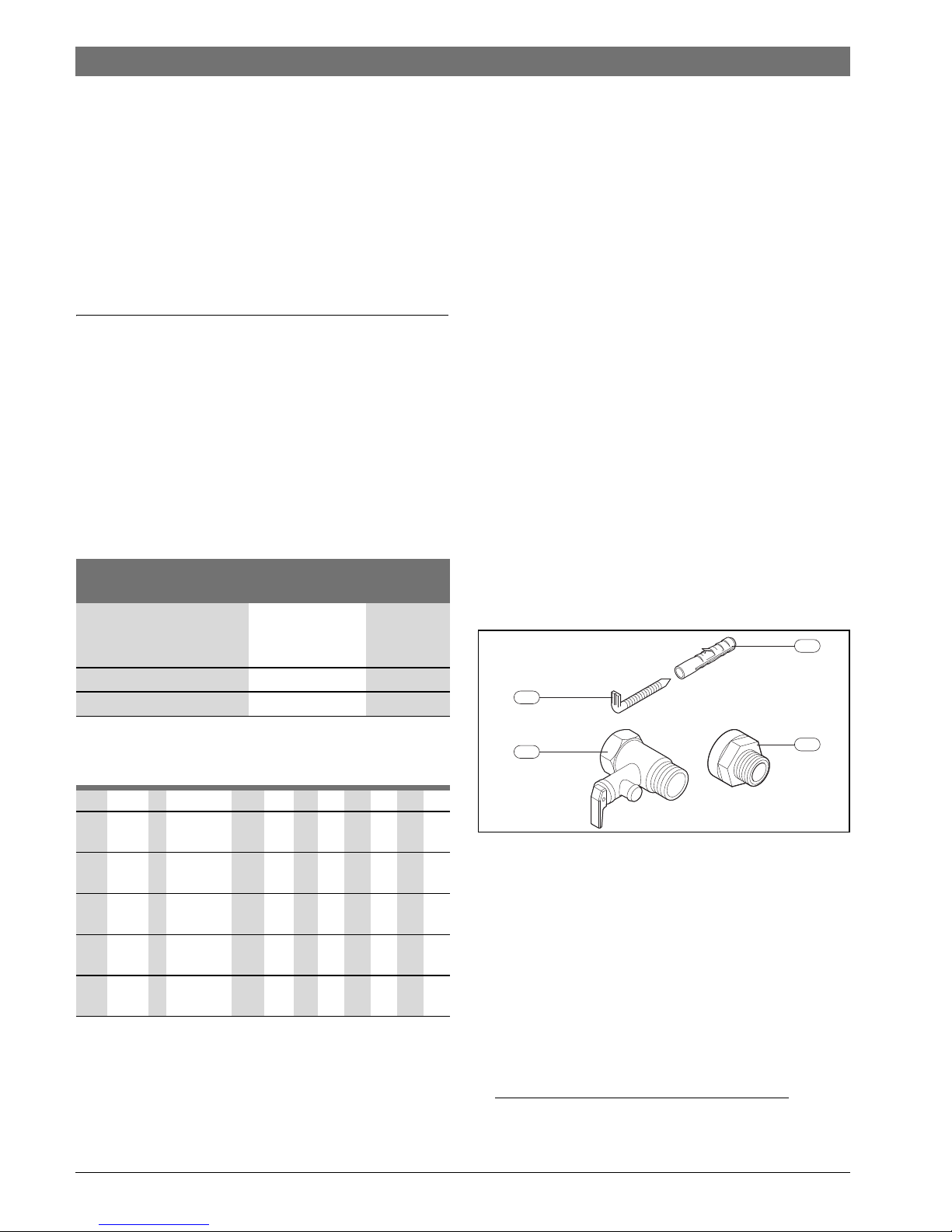
2.5 accessories
Fig. 1
[1] Screws (2x)
1)
[2] Rawl plug (2x)
1)
[3] Pressure relief valve (8 bar)
1)
[4] Isolation fitting (2x)
1)
Requirements for
potable water
Units
Water hardness, min. ppm
grain/US gallon
°dH
120
7.2
6.7
pH, min. – max. 6.5 – 9.5
Conductivity, min. – max. μS/cm 130 – 1500
Table 2 Requirements for potable water
ES 035 5 1200 W BO H1 XCTWVB
ES 050 5 1600 W
1500 W
BO H1M1XCTWRVB
ES 080 5 2000 W BO H1M1XCTWRVB
ES 100 5 2000 W BO H1M1XCTWRVB
ES 120 5 2000 W BO H1M1XCTWRVB
ES 150 5 2400 W
2000 W
BO H1M1XCTWRVB
Table 3
1) Only some models
6720801526-01.2V
3
1
2
4
6 720 818 731 (2016/07)Tronic 4000 T | Tronic 6000 T
Technical properties and dimension's | 5
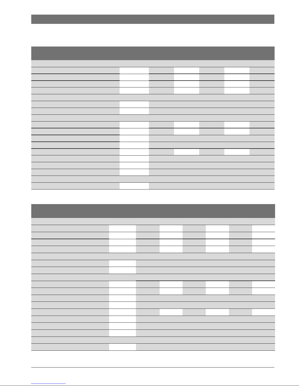
2.6 Technical data
This appliance meets the requirements specified by the European Directives 2014/35/EC and 2014/30/EC.
Tronic 4000 T
Technical data Units ES 050 ES 080 ES 100 ES 120 ES 150
General Information
Capacity l 48 77 95 115 143
Dry weight kg 18,8 22,5 25,8 29,3 35
Weight when full kg 66,8 99,5 120,8 144,3 178
Standing loss kW/24h 0,73 0,91 1,03 1,28 1,43
Water data
Max. permissible operating pressure bar 8
Water connections inch 1/2
Electrical data
Rated output W 1500 2000 2000 2000 2000
Heat-up time (T- 50 °C) 1 h 52 min 2 h 14 min 2 h 47 min 3 h 22 min 4 h 09 min
Supply voltage VAC 230
Frequency Hz 50
Electrical current (single phase) A 6,5 8,7 8,7 8,7 8,7
Power cable with plug (type) HO5VV - F 3 x 1,5 mm2 or HO5VV - F 3 x 1,0 mm
2
Protection class I
IP-Rating IP24
DHW temperature
Temperature range °C up to 70 °C
Table 4 Technical data
Tronic 6000 T
Technical data Units ES 035 ES 050 ES 080 ES 100 ES 120 ES 150
General Information
Capacity l 34 47 76 95 115 142
Dry weight kg 15,7 19,2 22,5 25,8 29,3 35
Weight when full kg 49,7 66,2 98,5 120,8 144,3 177
Standing loss kW/24h 0,78 0,73 0,91 1,03 1,28 1,43
Water data
Max. permissible operating pressure bar 8
Water connections inch 1/2
Electrical data
Rated output W 1200 1600 2000 2000 2000 2400
Heat-up time (T- 50 °C) 1 h 40 min 1 h 44 min 2 h 14 min 2 h 46 min 3 h 21 min 3 h 27 min
Supply voltage VAC 230
Frequency Hz 50
Electrical current (single phase) A 5,2 6,9 8,7 8,7 8,7 10,4
Power cable with plug (type) HO5VV - F 3 x 1,5 mm2 or HO5VV - F 3 x 1,0 mm
2
Protection class I
IP-Rating IP24
DHW temperature
Temperature range °C up to 70 °C
Table 5 Technical data
 Loading...