

Bosch ES025, ES049, ES035, ES061, ES071 Installation And Maintenance Manual
ES Series Heat Pump
ES025 | ES035 | ES049 | ESO61 | ES071
Installation and Maintenance Manual
T111970-291 (01/2015)

2 | ES Series
CONTENTS
Model Nomenclature.......................................................... 3
Initial Inspection................................................................4
General Description........................................................... 4
Moving and Storage...........................................................4
Location............................................................................ 4
INSTALLATION .................................................................. 5
MOUNTING VERTICALLY...............................................5
MOUNTING HORIZONTALY............................................ 5
HANGING BRACKET KIT.................................................6
CONDENSATE DRAIN .........................................................7
Duct System...................................................................... 7
Piping ...............................................................................8
Electrical .......................................................................... 8
ECM INTERFACE BOARD............................................... 9
Thermostat Connections ....................................................9
Safety Devices and the UPM Controller .............................11
UPM Sequence of Operation.........................................14
Troubleshooting.............................................................. 25
Electronic Thermostat Installation ................................... 29
Operating temperatures and Pressures..............................30
Wiring diagrams.............................................................. 35
Notes ............................................................................. 39
Electric Heater Package Option ........................................15
Heat Recovery Package ...................................................16
Water Tank Preparation: .............................................16
HR Water Piping ........................................................ 16
Water Tank Refill .............................................................17
Initial Start-Up........................................................... 17
Hot Gas Reheat (HGRH)..............................................17
Sequence of Operation ....................................................18
Cooling Mode ............................................................18
Heating Mode............................................................18
Application considerations............................................... 18
Well Water Systems ................................................... 18
Installation of Pressure Regulating Valves......................... 19
Cooling Tower/Boiler Systems.......................................... 19
Geothermal (Earth-Coupled) Systems ..........................21
System Checkout.............................................................22
Unit Start-up ................................................................... 22
Maintenance ...................................................................22
Unit Check-Out Sheet ......................................................24
Customer Data ..........................................................24
Unit Nameplate Data .................................................. 24
Operating Conditions ................................................. 24
Auxiliary Heat............................................................24
ES SeriesT111970291 (2015/01) Subject to change without prior notice
MODEL NOMENCLATURE
y
Model Nomenclature | 3ES Series
1XX XXSBA
X
1 - 100 VA
Economizer
P - DDC - Multi-Protocol (BacNET, Modbus, N2) w/ Expander
O - Carrier Open
C - Hot Gas Bypass with Hot Gas Reheat
C - Compressor Monitor Rel ay
G - Boilerless control
N - Comfort Alert
Z - EMS relay + Pump/Valve Relay
ES 25- 1VTC -F L T T U A - XXSAMXXXX 5A X X
049 S - Standard
061 A - Special #1
025
ES Code String Rev Level
Size B - Bosch
071 B - Special #2
035 Standard/Special
Voltage AIR FILTRATION
2 277/60/1 4 - MERV8 - 2" w/ 2" 4-SIDED FILTER RACK
3 208-230/60/3 5 - MERV13 - 2" w/ 2" 4-SIDED FILTER RACK
4 460/60/3
1 208-230/60/1 3 - STANDARD THROWAWAY FILTER w/ 2" 4-SIDED FILTER RACK
Cabinet Conguration X - None
Fiberglass Application
F - G90 Steel / 1/2" Cl osed Cell Foam, Extra Quiet
D - G90 Steel / 1/2" Standard 1.5LB Dual Density Fiberglass, Extra Quiet
D - 15 kW
A - 5 kW K - Fire Alarm Relay/Dual Power
E - 20 kW X - As default for non used electrical codes
C - 10 kW M - Wire to 208 V
L - Left Transformer
HZ - Horizontal E - Economizer With 3 Way Valve and Controls
VT - Vertical
CF - Downow (Count erow) X - None
C - Copper X - Standard
N - Cupro-Nickel M - DDC - Multi-Protocol (BacNET, Modbus, N2)
Coax Options Controls
F - Front G - DDC - LonWorks w/ Expander
Water Connections L - DDC - LonWorks
R - Right 7 - 75 VA
T - Top Refrigeration Circu it Options
S - Straight X - None
E - End H - Hot Gas Reheat - On/O
Return Air Conguration
Discharge Air Conguration
B - Bottom B - Hot Gas Bypass
Air Coil General Electrical Options (up to 5 available per unit)
A - Constant Airow ECM S - Straight Cool
Fan/Motor Options D - Heat Recovery Package
ion Level D - Phase Monitor
U - Uncoated A - EMS relay
T - Tin Plated B - Blower Monitor Relay
Revis
X - None J - Disconnect Switch
A - Current E - Pump/val ve relay
Electric Heat (Du al Power Connection) H - Flow proving switch
C - G90 Steel / 1/2" Cl osed Cell Foam G - EXTENDED RANGE W/ SCHRADER VALVE (Geothermal)
A - G90 Steel / 1/2" S tandard 1.5LB Dual Densi t
Cabinet Construction
Figure # 1
T111970291 (2015/01)ES Series
4 | Initial Inspection ES Series
WARNING: Installation and servicing of this
equipment can be hazardous due to system
pressure and electrical components. Only
trained and qualified personnel should
install, repair, or service the equipment.
WARNING: Before performing service or
maintenance operations on the system, turn
off main power to the unit. Electrical shock
could cause personal injury or death.
CAUTION: When working on equipment,
always observe precautions described in
the literature, tags, and labels attached to
the unit. Follow all safety codes. Wear
safety glasses and work gloves. Use a
quenching cloth for brazing, and place a fire
extinguisher close to the work area.
NOTE: All refrigerant discharged from this
unit must be recovered WITHOUT
EXCEPTION. Technicians must follow
industry accepted guidelines and all local,
state, and federal statutes for the recovery
and disposal of refrigerants. If a compressor
is removed from this unit, refrigerant circuit
oil will remain in the compressor. To avoid
leakage of compressor oil, refrigerant lines
of the compressor must be sealed after it is
removed.
NOTE: To avoid equipment damage, DO
NOT use these units as a source of heating
or cooling during the construction process.
Doing so may affect the unit’s warranty. The
mechanical components and filters will
quickly become clogged with construction
dirt and debris, which may cause system
damage.
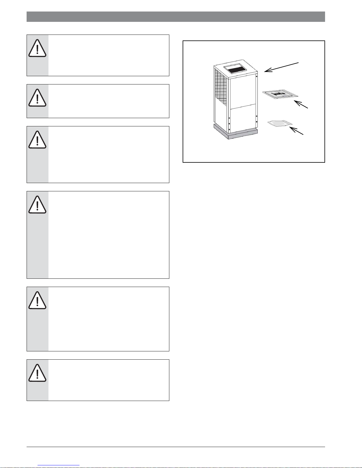
INITIAL INSPECTION
1
2
3
Figure # 2
[1] ES Series Water-to-Air Heat Pump
[2] Installation and Operation Manual
[3] Hanging Bracket kit (HZ unit only)
Be certain to inspect all cartons or crates on each
unit as received at the job site before signing the
freight bill. Verify that all items have been received
and that there are no visible damages; note any
shortages or damages on all copies of the freight
bill. In the event of damage or shortage, remember
that the purchaser is responsible for filing the
necessary claims with the carrier. Concealed
damages not discovered until after removing the
units from the packaging must be reported to the
carrier within 24 hours of receipt.
GENERAL DESCRIPTION
ES Series Water-to-Air Heat Pumps provide the
best combination of performance and efficiency
available. Safety devices are built into each unit to
provide the maximum system protection possible
when properly installed and maintained.
NOTE: To avoid the release of refrigerant
into the atmosphere, the refrigerant circuit
of this unit must be serviced only by
technicians who meet local, state, and
federal proficiency requirements.
All ES water to Air Heat Pumps conform to UL1995
standard and are certified to CAN/CSA C22.2 No
236 by Intertek-ETL.The Water-to-Air Heat Pumps
are designed to operate with entering fluid
temperature between 20°F to 90°F in the heating
mode and between 30°F to 120°F in the cooling
mode.
ES SeriesT111970291 (2015/01) Subject to change without prior notice
NOTE: 50° Minimum Entering Water
Temperature (EWT) for well water applications
with sufficient water flow to prevent freezing.
Antifreeze solution is required for all closed loop
applications. Cooling Tower/Boiler and
Geothermal applications should have sufficient
antifreeze solution to protect against extreme
conditions and equipment failure. Frozen water
coils are not covered under warranty.
NOTE: This product should not be used for
temporarily
heating/cooling during construction. Doing
so may affect the units warranty.
MOVING AND STORAGE
If the equipment is not needed for immediate
installation upon its arrival at the job site, it should
be left in its shipping carton and stored in a clean,
dry area. Units must only be stored or moved in the
normal upright position as indicated by the “UP”
arrows on each carton at all times.
For storage If unit stacking is required,
stack units as follows:
Do not stack units larger than 6 tons.
Vertical units less than 6 tons, no more than
two high.
Horizontals units less than 6 tons, no more
than three high.
LOCATION
Locate the unit in an indoor area that allows easy
removal of the filter and access panels, and has
enough room for service personnel to perform
maintenance or repair. Provide sufficient room to
make fluid, electrical, and duct connection(s). If
the unit is located in a confined space such as a
closet, provisions must be made for return air to
freely enter the face of unit’s air coil. On horizontal
units, allow adequate room below the unit for a
condensate drain trap and do not locate the unit
above supply piping.
NOTE: These units are not approved for
outdoor installation; therefore, they must
be installed inside the structure being
conditioned. Do not locate in areas that are
subject to freezing.
Moving and Storage | 5ES Series
INSTALLATION
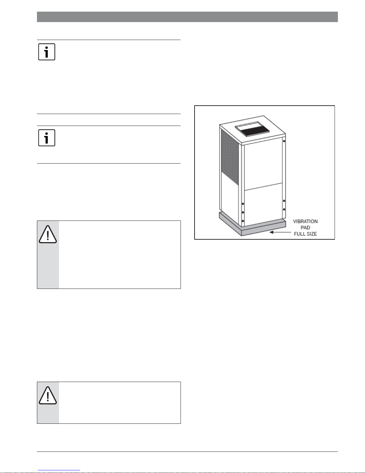
MOUNTING VERTICALLY
Vertical units up to six tons are available in left or
right air return configurations. Vertical units
should be mounted level on a vibration absorbing
pad slightly larger than the base to minimize
vibration transmission to the building structure. It
is not necessary to anchor the unit to the floor.
(See Figure #3).
Figure # 3
MOUNTING HORIZONTALY
While horizontal units may be installed on any level
surface strong enough to hold their weight, they
are typically suspended above a ceiling by
threaded rods. The rods are usually attached to the
unit corners by hanger bracket kits
The rods must be securely anchored to the ceiling.
Refer to the hanging bracket assembly and
installation instructions for details. Horizontal
units installed above the ceiling must conform to
all local codes. An auxiliary drain pan if required by
code, should be at least four inches larger than the
bottom of the heat pump.
Some applications require an attic floor
installation of the horizontal unit. In this case the
unit should be set in a full size secondary drain pan
on top of a vibration absorbing mesh. The
secondary drain pan prevents possible condensate
overflow or water leakage damage to the ceiling.
The secondary drain pan is usually placed on a
plywood base isolated from the ceiling joists by
additional layers of vibration absorbing mesh. In
both cases, a 3/4” drain connected to this
secondary pan should be run to an eave at a
location that will be noticeable.
T111970291 (2015/01)ES Series
6 | Hanging Bracket Kit ES Series
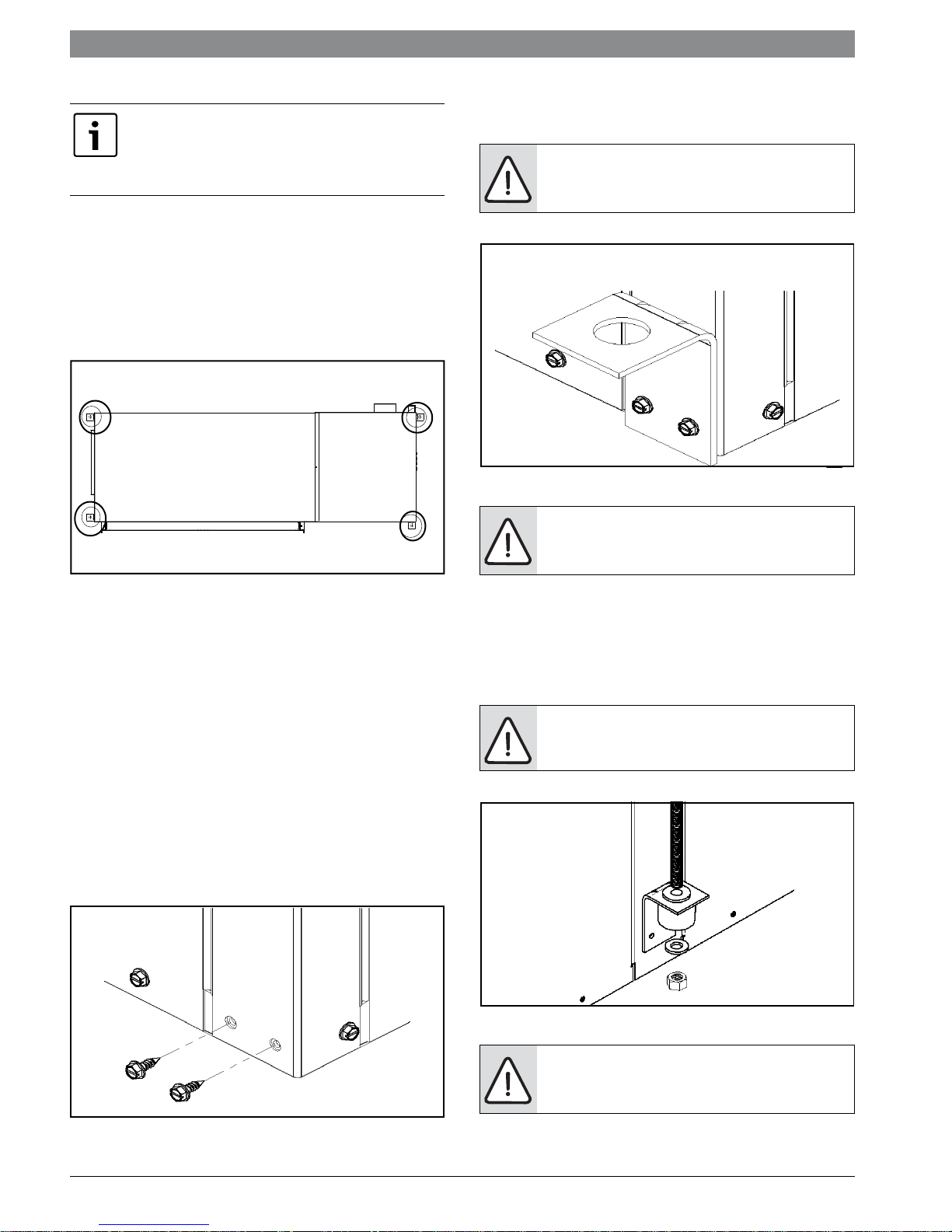
2. Mount 4 Brackets to unit corner post using the
NOTE: IF unit is located in a crawl space, the
bottom of the unit MUST be at least 4” above
grade to prevent flooding of the electrical parts
due to heavy rains.
bolts provided in the kit as shown on Figure#6.
WARNING: Do not re-use screws removed
from the unit on step 1 to mount the
Hanging brackets to the unit.
HANGING BRACKET KIT
Installation instructions
All horizontal units come with Hanging Bracket Kit
facilitate suspended unit mounting using threaded
rod. Hanging brackets are to be installed as shown
in Figure#4.
Figure # 6
Figure # 4
This Kit includes the following:
(5) Brackets
(5) Rubber Vibration isolators
(8) Screws #10x1/2
(10) Bolts 1/4-28x12” Hex Bolt (not used for these
models)
The following are needed and are to be field
provided:
Threaded rod (3/8” max dia)
Hex Nuts
Washers (1-3/4” min O.D.)
1. Remove and discard factory provided screws
from locations where hanging brackets will be
installed shown in Figure# 5.
WARNING: Follow all applicable codes and
requirements when hanging this unit,
selecting threaded rod material, etc.
3. Install rubber grommet onto the Brackets as
shown in Figure#7.
4. Hang the unit and assemble the field provided
threaded rod, nuts and washers on to the brackets
as shown in Figure#7
WARNING: Rods must be securely
anchored to the ceiling.
Figure # 5
Figure # 7
NOTE: Plumbing connected to the heat
pump must not come in direct contact with
joists, trusses, walls, etc.
ES SeriesT111970291 (2015/01) Subject to change without prior notice
CONDENSATE DRAIN | 7ES Series
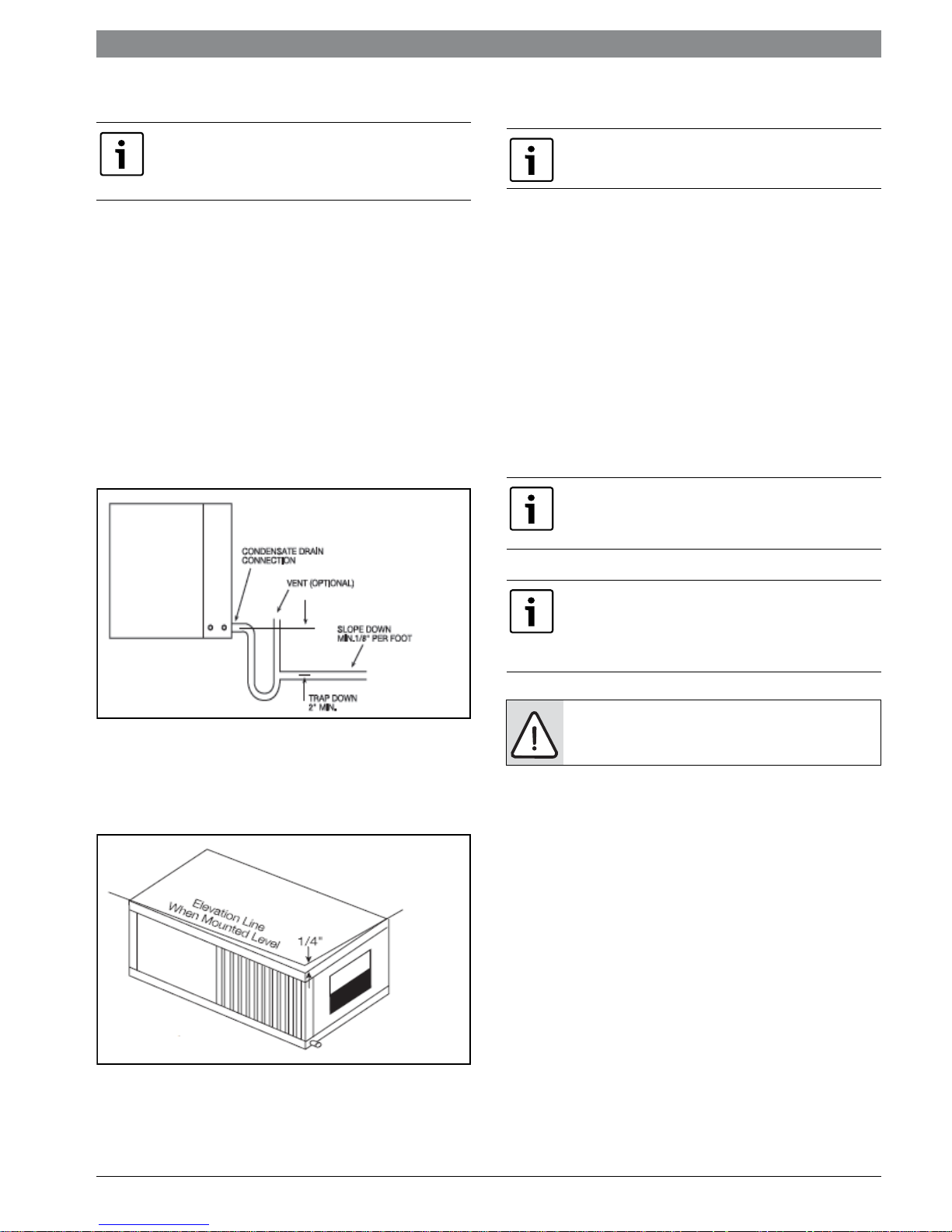
CONDENSATE DRAIN
If equipped with float style condensate
overflow switch, final adjustment must be
made in the field.
A drain line must be connected to the heat pump
and pitched away from the unit a minimum of 1/8”
per foot to allow the condensate to flow away from
the unit.
This connection must be in conformance with local
plumbing codes. A trap must be installed in the
condensate line to insure free condensate flow.
(Heat Pumps are not internally trapped).
A vertical air vent is sometimes required to avoid
air pockets.(See Figure #5).
The length of the trap depends on the amount of
positive or negative pressure on the drain pan. A
second trap must not be included.
DUCT SYSTEM
Supply air duct and return air duct flanges are
shipped unfolded with unit.
A supply air outlet collar and return air duct flange
are provided on all units to facilitate duct
connections. Fold the duct flange outwards along
the perforated line. Refer to unit Dimensional
Drawings for physical dimensions of the collar and
flange. (Pg#17 through Pg#20)
A flexible connector is recommended for supply
and return air duct connections on metal duct
systems. All metal ducting should be insulated
with a minimum of one inch duct insulation to
avoid heat loss or gain and prevent condensate
forming during the cooling operation.
NOTE: Application of the unit to no insulated
duct work is not recommended as the unit’s
performance will be adversely affected.
Figure # 8
The horizontal unit should be pitched
approximately 1/4” towards the drain in both
directions, to facilitate condensate removal. (See
Figure #6)
Figure # 9
NOTE: The factory provided air filter must be
removed when using a filter back return air grill.
The factory filter should be left in place on a free
return system
NOTE: Do not connect discharge ducts
directly to the blower outlet.
If the unit will be installed in a new installation
which includes new duct work, the installation
should be designed using current ASHRAE
procedures for duct sizing.
If the unit is to be connected to existing duct work,
a check should be made to assure that the duct
system has the capacity to handle the air required
for the unit application. If the duct system is too
small, larger duct work should be installed. Check
for existing leaks and repair.
The duct system and all diffusers should be sized
to handle the designed air flow quietly. To
maximize sound attenuation of the unit blower, the
supply and return air plenums should be insulated.
There should be no direct straight air path thru the
return air grille into the heat pump.
T111970291 (2015/01)ES Series
8 | Piping ES Series
The return air inlet to the heat pump must have at
least one 90 degree turn away from the space
return air grille.
If air noise or excessive air flow are a problem, the
blower speed can be changed to a lower speed to
reduce air flow.
(Refer to ECM motor interface board section in
this manual and Table#1)
PIPING
Supply and return piping must be as large as the
unit connections on the heat pump (larger on long
runs).
NOTE: Never use flexible hoses of a smaller
inside diameter than that of the fluid
connections on the unit.
ES units are supplied with either a copper or
optional cupro-nickel condenser. Copper is
adequate for ground water that is not high in
mineral content.
NOTE: Proper testing is recommended to
assure the well water quality is suitable for use
with water source equipment.
In conditions anticipating moderate scale
formation or in brackish water a cupro-nickel heat
exchanger is recommended.
NOTE: Do not overtighten the connections.
Flexible hoses should be used between the unit
and the rigid system to avoid possible vibration.
Ball valves should be installed in the supply and
return lines for unit isolation and unit water flow
balancing.
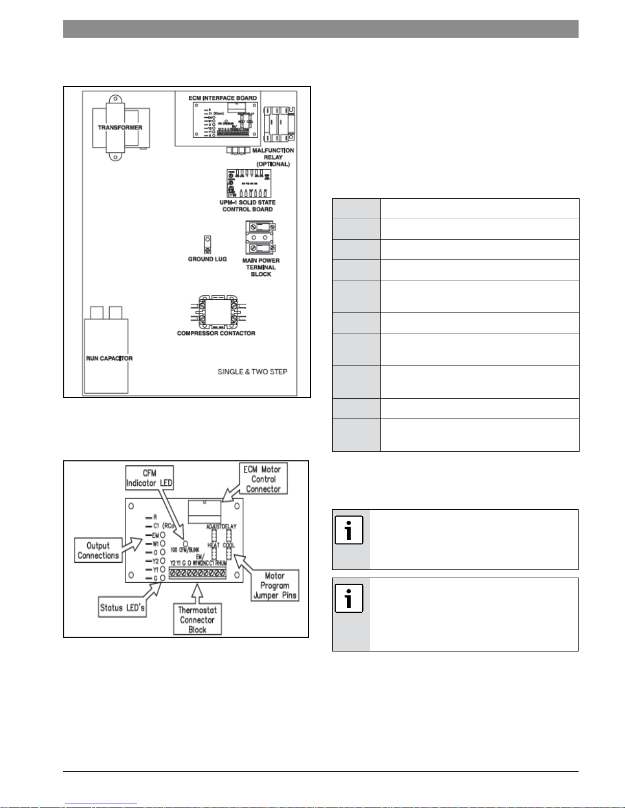
ELECTRICAL
Refer to electrical component box layout.
(Figure#7)
WARNING: Field wiring must comply
with local and national electric codes.
WARNING: Power to the unit must be
within the operating voltage range
indicated on the unit nameplate or on
the performance data sheet.
WARNING: Operation of unit on
improper line voltage or with excessive
phase imbalance will be hazardous to
the unit, constitutes abuse and may
void the warranty.
NOTE: Both the supply and discharge water
lines will sweat if subjected to low water
temperature. These lines should be insulated to
prevent damage from condensation.
All manual flow valves used in the system must be
ball valves. Globe and gate valves must not be used
due to high pressure drop and poor throttling
characteristics.
NOTE: Never exceed the recommended
water flow rates as serious damage or
erosion of the water-to-refrigerant heat
exchanger could occur.
Always check carefully for water leaks and repair
appropriately. Units are equipped with female pipe
thread fittings. Consult Unit Dimensional
Drawings. (Pg#17 through Pg#20)
NOTE: Teflon tape sealer should be used when
connecting water piping connections to the units
to insure against leaks and possible heat
exchanger fouling.
Properly sized fuses or HACR circuit breakers must
be installed for branch circuit protection. See unit
nameplate for maximum fuse or breaker size.
The unit is provided with a concentric knock-out
for attaching common trade sizes of conduit, route
power supply wiring through this opening. Always
connect the ground lead to the grounding lug
provided in the control box and power leads to the
line side of compressor contactor as indicated on
the wiring diagram and Figure #5.
NOTE: Units supplied with internal electric heat
require two (2) separate power supplies:
1) Unit compressor
2) Electric Heat, blower motor and control
circuit.
NOTE: Refer to the ELECTRIC HEATER
PACKAGE OPTION section and Figure # 11 for
wiring diagrams. See data plate for minimum
circuit ampacities and maximum fuse/breaker
sizing.
ES SeriesT111970291 (2015/01) Subject to change without prior notice
Thermostat Connections | 9ES Series
THERMOSTAT CONNECTIONS
Thermostat wiring is connected to the 10 pin
screw type terminal block on the lower center
portion of the ECM Interface Board. In addition to
providing a connecting point for thermostat wiring,
the interface board also translates thermostat
inputs into control commands for the Electronic
Commutated Motor (ECM) DC fan motor and
displays an LED indication of operating status. The
thermostat connections and their functions are as
follows:
Y1 First Stage Compressor Operation
Y2 Second Stage Compressor Operation
G Fan
O Reversing Valve (energized in cooling)
W1 Auxiliary Electric Heat (runs in
conjunction with compressor)
EM/W2 Emergency Heat (electric heat only)
Figure # 10
ECM INTERFACE BOARD
Figure # 11
NC Transformer 24 VAC Common (extra
connection)
C1 Transformer 24 VAC Common
(primary connection)
R Transformer 24 VAC Hot
HUM Dehumidification Mode (not used in
ES Series)
If the unit is being connected to a thermostat with
a malfunction light, this connection is made at the
unit malfunction output or relay.
If the thermostat is provided with a malfunction
light powered off of the common (C) side of the
transformer, a jumper between “R” and “COM”
terminal of the “ALR” contacts must be made.
If the thermostat is provided with a malfunction
light powered off of the hot (R) side of the
transformer, then the thermostat malfunction
light should be connected directly to the (ALR)
contact on the unit’s UPM board.
To the left of the thermostat connection block are
a row of 2 red and 4 green LED’s. These LED’s
indicate the operating status of the unit. They are
labeled as follows:
T111970291 (2015/01)ES Series
10 | Thermostat Connections ES Series
The TEST position is used to verify proper motor
EM (Red) Emergency Heat On
operation. If a motor problem is suspected, move
the ADJ jumper to the TEST position and energize
W1 (Red Auxiliary Heat On
G on the thermostat connection block. If the motor
ramps up to 100% power, then the motor itself is
O (Green) Reversing Valve Energized, unit is
in Cooling Mode
Y2
Second Stage Compressor On
functioning normally. Always remember to replaES
the jumper to NORM, (+) or (-) after testing and
reset the unit thermostat to restore normal
operation.
(Green)
Y1
First Stage Compressor On
(Green)
G (Green) Fan On
Just above the connector block is a single red
LED labeled CFM that will blink intermittently
when the unit is running and may flicker when
the unit is off.
This LED indicates the air delivery of the blower at
any given time. Each blink of the LED represent
approximately 100 CFM of air delivery so if the LED
blinks 12 times, pauses, blinks 12 times, etc. the
blower is delivering approximately 1200 CFM.
Refer to Figure #9 for factory programmed air
delivery settings for the ES Series.
To the right of the thermostat connection block is
a green LED labeled dehumidify.
Just above and to the right of the thermostat connection
block are four sets of jumper pins labeled ADJ,
DELAY, HEAT and COOL. The ADJ set of pins are
labeled NORM, (+), (-) and TEST. ES units will all
be set on the NORM position from the factory,
however, airflow can be increased (+) or
decreased (-) by 15% from the pre-programmed
setting by relocating the jumper in this section.
Do not set the ADJ DIP switch to the (-)
setting when electric heaters are installed.
Doing so may cause the heaters to cycle on
their thermal overload switches, potentially
shortening the life of the switches.
The other DIP switch bank is used to select the
proper program in the ECM motor for the unit.
Refer to Figure #7 for the proper jumper
placement.
WARNING: Always disconnect power
before changing jumper positions on the
interface board and reset the unit
afterward.
WARNING: Remember to always turn
off unit power at the circuit breaker
before attaching or disconnecting any
wiring from these connections to avoid
accidental short circuits that can
damage unit control components.
To the left of the red and green status LED’s is a
row of 1/4” male quick connects. These are used
to pass thermostat inputs on to the rest of the
control circuit.
Heater
Model
ES025 450 500 800 800 800 900 700 A
ES035 700 800 1200 1200 1200 1400 1000 A
ES049 900 1000 1600 1600 1600 1800 1400 B
ES061 1200 1400 2000 2000 2000 2100 1900 A
ES071 1600 1600 2200 2200 2200 2300 1900 A
Fan
Only
Y1
Cool/
Heat
Figure # 12 Motor Profile Air Flow CFM Two Stage Units
Cool/
Y2
Heat
AUX
Heat
EMERG
Heat
PLUS
Adj
MINUS
Adj
TAP
COOL/
HEAT/
DELAY
ES SeriesT111970291 (2015/01) Subject to change without prior notice
Safety Devices and the UPM Controller | 11ES Series
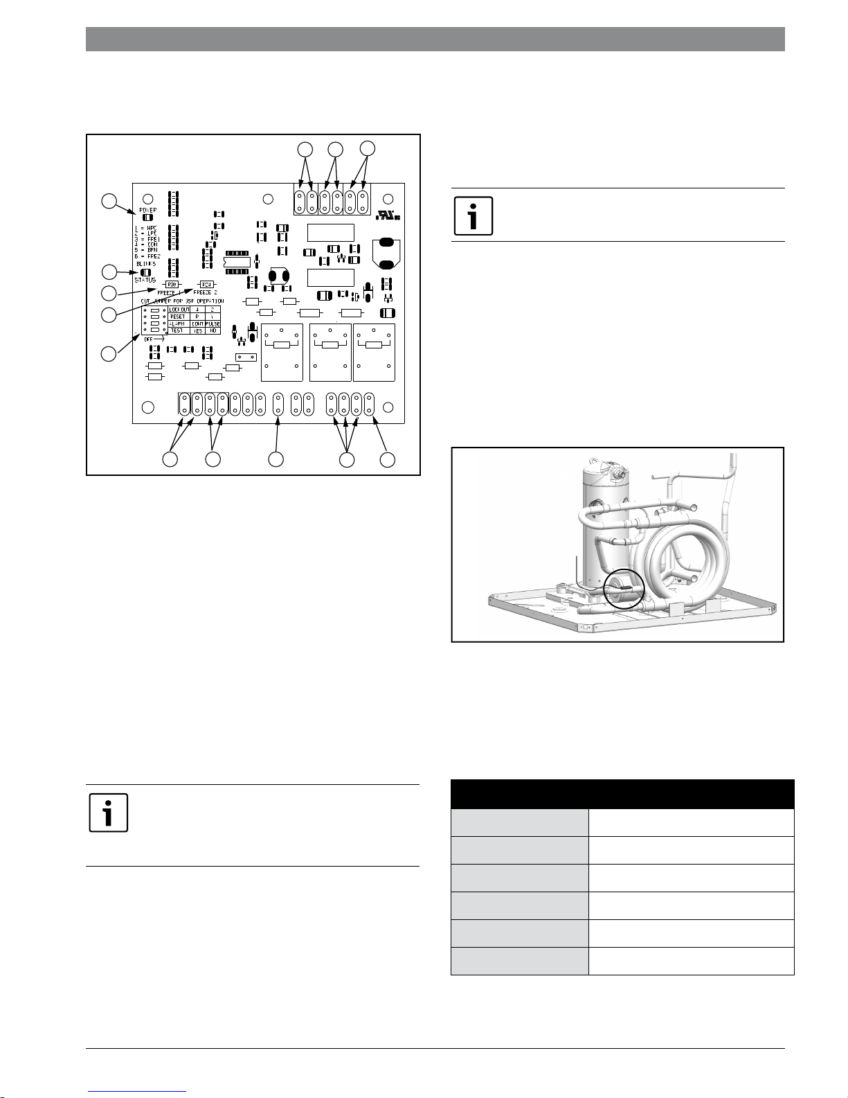
SAFETY DEVICES AND THE UPM
CONTROLLER
11
1213
1
2
3
4
5
6
[1] Board power indicator
[2] UPM Board LED indicator
[3] Water coil freeze protection temperature
selection
[4] Air coil freeze protection temperature selection
[5] UPM board settings
[6] Water coil freeze connection
[7] Air coil freeze connection
[8] LCD connection
[9] 24VAC power hot
[10] To compressor contactor
[11] High pressure switch connection
[12] Call for compressor
[13] Low pressure switch connection
[14] 24VAC power common
NOTE: If the unit is being connected to a
thermostat with a malfunction light, this
connection is made at the unit malfunction
output or relay.
78
Figure # 13
10
9
• High pressure switch located in the refrigerant
discharge line and wired across the HPC
terminals on the UPM
• Low pressure switch located in the unit
refrigerant suction line and wired across
terminals LPC1 and LPC2 on the UPM.
UPM Board Dry Contacts are Normally Open
(NO)
• Water side freeze protection sensor, mounted
close to condensing water coil, monitors
refrigerant temperature between condensing
water coil and thermal expansion valve. If
temperature drops below or remains at freeze
limit trip for 30 seconds, the controller will
shut down the compressor and enter into a
soft lockout condition. The default freeze limit
trip is 26°F, however this can be changed to
15°F by cutting the R42 resistor located on top
of DIP switch SW1. (Figure #11)
•
Figure # 14
• The optional condensate overflow protection
sensor (standard on horizontal units) is
located in the drain pan of the unit and
connected to the ‘COND’ terminal on the UPM
board. (Figure #10)
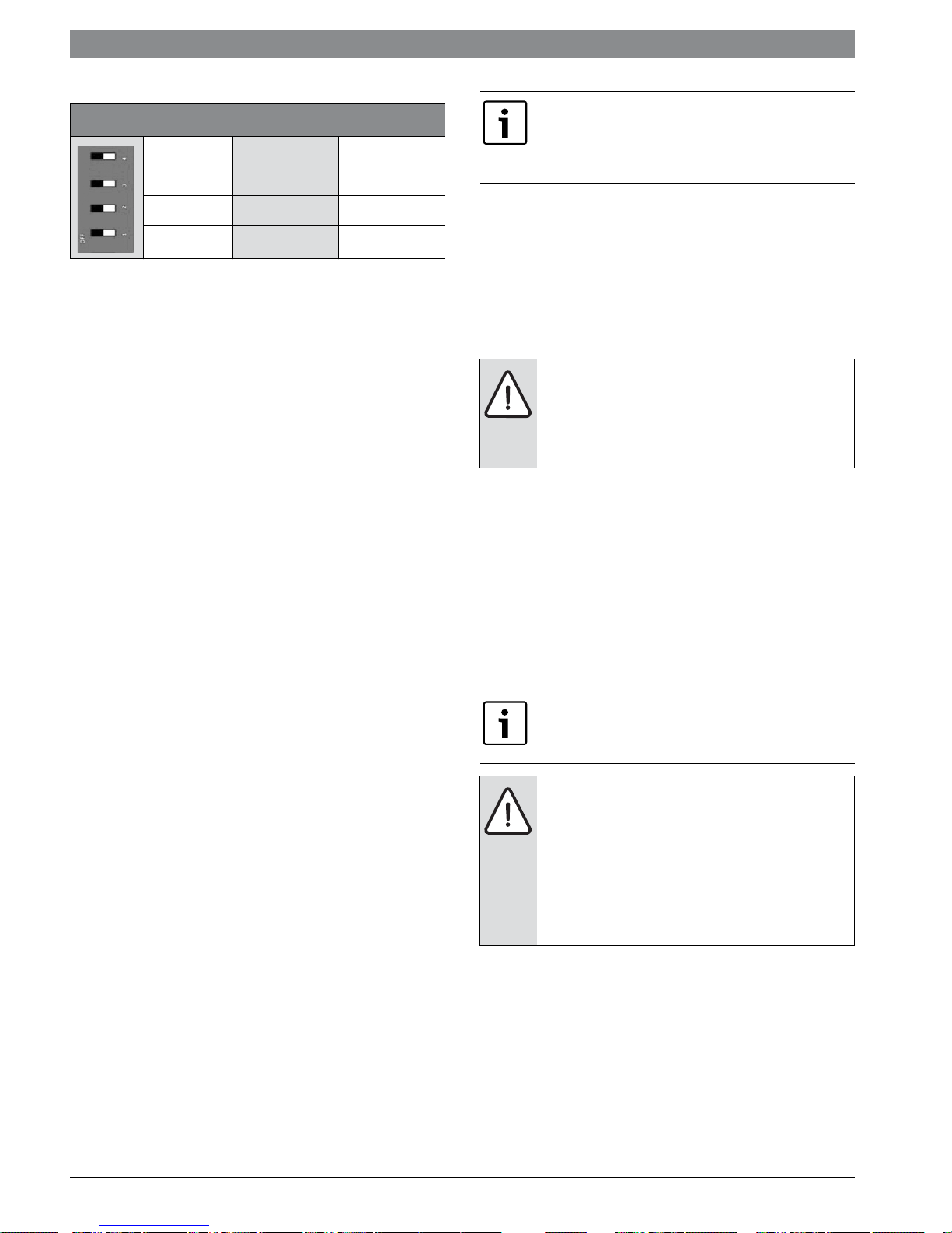
UPM Board Factory Default Settings
TEMP
LOCKOUT
26°F
2
Each unit is factory provided with a Unit Protection
Module (UPM) that controls the compressor
operation and monitors the safety controls that
protect the unit.
Safety controls include the following:
RESET
ALARM
TEST
HOT/DRY ALARM
Y
PULSE
NO
NO
T111970291 (2015/01)ES Series
12 | Safety Devices and the UPM Controller ES Series
UPM DIP SWITCH DEFAULT POSITION
lockout 42
reset
alarm
test yes no
The UPM Board includes the following features:
• ANTI-SHORT CYCLE TIMER: 5 minute delay on
break timer to prevent compressor short cycling.
• RANDOM START: Each controller has an unique
random start delay ranging from 270 to 300 seconds
on initial power up to reduce the chance of multiple
unit simultaneously starting at the same time after
power up or after a power interruption, thus
avoiding creating large electrical spike.
• LOW PRESSURE BYPASS TIMER: If the
compressor is running and the low pressure switch
opens, the controller will keep the compressor ON
for 120 seconds. After 2 minutes if the low pressure
switch remains open, the controllers will shut down
the compressor and enter a soft lockout. The
compressor will not be energized until the low
pressure switch closes and the anti-short cycle time
delay expires. If the low pressure switch opens 2-4
times in 1 hour, the unit will enter a hard lockout. In
order to exit hard lockout, power to the unit would
need to be reset.
• BROWNOUT/SURGE/POWER
INTERRUPTION PROTECTION: The brownout
protection in the UPM board will shut down the
compressor if the incoming power falls below 18
VAC. The compressor will remain OFF until the
voltage is above 18 VAC and ANTI-SHORT CYCLE
TIMER (300 seconds) times out. The unit will not go
into a hard lockout and does not need to be reset.
• MALFUNCTION OUTPUT: Alarm output is
Normally Open (NO) dry contact.
selected the alarm output will be pulsed. The
fault output will depend on the dip switch
setting for “ALARM”. If it is set to “CONST”, a
constant signal will be produced to indicate a
fault has occurred and the unit requires
inspection to determine the type of fault. If it is
set to “PULSE”, a pulse signal is produced and
a fault code is detected by a remote device
indicating the fault. See L.E.D Fault Indication
below for blink code explanation. The remote
device must have a malfunction detection
capability when the UPM board is set to
“PULSE”.
RY
Cont pulse
If pulse is
If 24 VAC output is needed R must be wired to
ALR-COM terminal; 24 VAC will be available o
the ALR-OUT terminal when the unit is in the
alarm condition.
• DISPLAY OUTPUT: The Display output is a pulse
output connected to the Unit Diagnostic Display
(UDD) and it pulses 24VAC when the unit is in an
lockout alarm condition.
• TEST DIP SWITCH: A test dip switch is provided
to reduce all time delays settings to 10 seconds
during troubleshooting or verification of unit
operation.
NOTE: Operation of unit in test mode can
lead to accelerated wear and premature
failure of components. The "TEST" switch
must be set back to "NO" after
troubleshooting/servicing.
• FREEZE SENSOR: The freeze sensor input is
active all the time, if a freeze option it not
selected the freeze terminals will need a
jumper. There are two (2) configurable freeze
points, 26°F & 15°F. The unit will enter a soft
lock out until the temperature climbs above
the set point and the anti-short cycle time
delay has expired. The freeze sensor will shut
the compressor output down after 90 seconds
of water flow loss and report a freeze
condition.
It is recommended to have a flow switch to
prevent the unit from running if water fl ow is
lost.
NOTE: If unit is employing a fresh water
system (no anti-freeze protection), it is
extremely important to have the Freeze1
R42 resistor set to 26°F in order to shut
down the unit at the appropriate leaving
water temperature and protect your heat
pump from freezing if a freeze sensor is
included.
ES SeriesT111970291 (2015/01) Subject to change without prior notice
• L.E.D. FAULT INDICATION: Two L.E.D.
indicators are provided:
Green: Power L.E.D. indicates 18-30 VAC
present on board.
Red: Fault indicator with the following blink
codes;
1 - High Pressure Lockout
2 - Low Pressure Lockout
3 - Freeze Sensor Lockout
4 - Condensate Overflow
5 - Brownout
• INTELLIGENT RESET: If a fault condition is
initiated, the 5 minute delay on break time
period is initiated and the unit will restart after
these delays expire. During this period the
fault LED will indicate the cause of the fault. If
the fault condition still exists or occurs 2 or 4
times (depending on 2 or 4 setting for Lockout
dip switch) before 60 minutes, the unit will go
into a hard lockout and requires a manual
lockout reset. A single condensate overflow
fault will cause the unit to go into a hard
lockout immediately, and will require a manual
lockout reset.
• LOCKOUT RESET: A hard lockout can be reset
by turning the unit thermostat off and then
back on when the “RESET” dip switch is set to
“Y” or by shutting off unit power at the circuit
breaker when the “RESET” dip switch is set to
“R”.
Safety Devices and the UPM Controller | 13ES Series
The blower motor will remain active during a
lockout condition.
NOTE: Always check incoming line
voltage power supply and secondary
control voltage for adequacy
T111970291 (2015/01)ES Series
14 | UPM Sequence of Operation ES Series
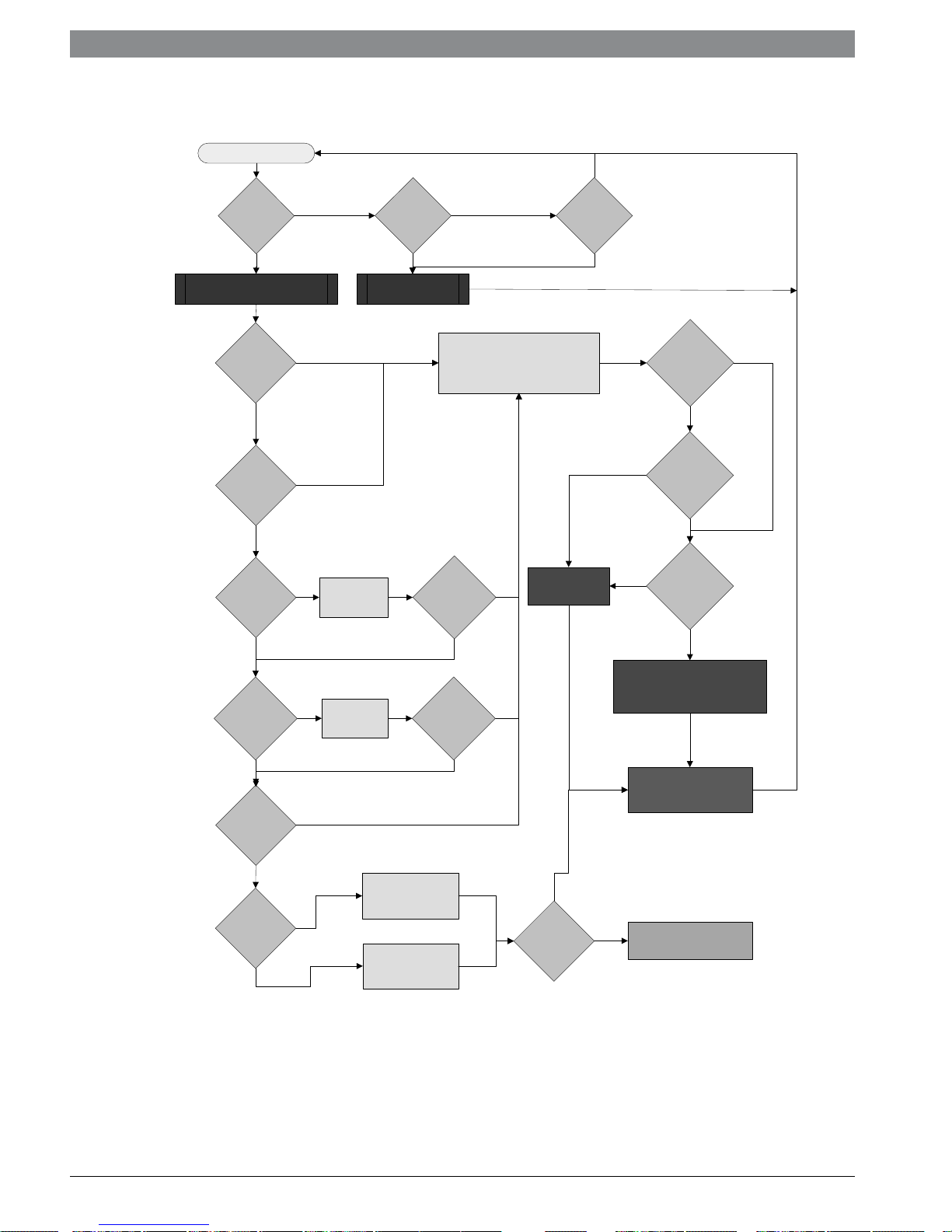
UPM SEQUENCE OF OPERATION
START
YES
Y1 = ON
NO
RESET ON
Y
NO
RESET ON R
R = 24VAC
YES
POWER/ SWITCHES/SENSOR
STATUS CHECK
V > 18VAC
NO
YES
HPC =
CLOSED
NO
YES
LPC
=CLOSED
NO
YES
FRZ >TEMP
LIMIT
NO
START
TIMER
START
TIMER
YES
CLEAR FAULTS
TIME > 120
NO
TIME > 30
BLINK CODE ON STATUS LED
SOFT LOCKOUT
RECORD ALARM
START COUNTER (IF APPLICABLE)
LOCKOUT CAN BE SET
TO 4 VIA DIP SWITCH
BLINK CODE
SEC
SEC
ON STATUS LED
YES
YES
NO
COUNTER
NEEDED?
YES
COUNT = 2
OR
COUNT = 4
NO
YES
NO
HARD
LOCKOUT?
YES
BLINK CODE ON STATUS LED
DISPLAY OUTPUT = PULSE
ALR OUTPUT = ON/PULSE
NO
YES
CON > 0
YES
INITIAL
POWER UP
YES
NO
NO
NO
START
ANTI SHORT CYCLE
START
RANDOM START UP
NO
T > ASC OR
RS SEC
CC
LEGEND:
HPC - HIGH PRESSURE CUTOUT
LPC - LOW PRESSURE CUTOUT
FRZ - FREEZE PROTECTION CONDITION
CON - CONDENSATE OVERFLOW CONDITION
CC - COMPRESSOR COIL
Figure # 15 UPM Sequence of Operation
CC OUTPUT = OFF
YES
CC OUTPUT = ON
ES SeriesT111970291 (2015/01) Subject to change without prior notice
Electric Heater Package Option | 15ES Series
ELECTRIC HEATER PACKAGE OPTION
WARNING: The HP series heater
package requires its own electrical
service separate from the heat pump’s
power supply. DO NOT attempt to wire
the package into the same circuit as the
heat pump.
Factory installed internal electric heater packages
are available for ES Series units. Two power
supplies are required when heater packages are
utilized. The power supply for the heater package
(located in the electric heater package control
box) provides power for the heater elements, the
blower motor and the control circuit for the unit.
The power supply for the unit provides power for
the compressor. This allows the electric heaters to
continue to operate along with the blower motor in
the case of unit compressor and/or compressor
power supply failure.
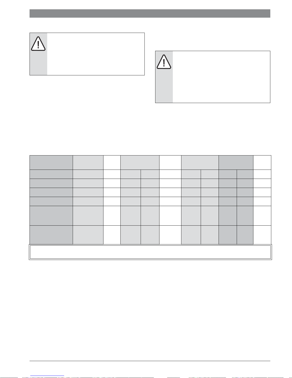
Model
Heater
Model
KW Heater AMPS Circuit MCA Max. Fuse
Each ES Series model has a number of heater sizes
available. Refer to Figure #13 for heater package
compatibility with specific ES series units, model
nomenclatures and electrical data.
NOTE: If heat recovery unit is installed in an
area where freezing may occur, the unit
must be drained during winter months to
prevent heat exchanger damage. Heat
exchanger ruptures that occur due to
freezing will void the heat recovery package
warranty along with the heat pump
warranty.
AWG
Min.
208V 240V 208V 240V 208V 240V
ES025 thru 035 HP050-1XS 4.8 17.3 20.0 L1/L2 27.1 30.4 30 30 8
ES049 thru 071 HP050-1XM 4.8 17.3 20.0 L1/L2 27.1 30.4 30 30 8
ES049 thru 071 HP100-1XM 9.6 34.7 40.0 L1/L2 49.5 56.3 50 60 6
ES049 thru 071 HP150-1XM
HP150-1XM
ES049 thru 071 HP200-1XM
HP200-1XM
All heaters rated single phase 60Hz, and include unit fan load. All fuses type “D” time delay, HACR type breaker or
HRC FORM 1. Wire size based on 60 deg. C copper conductors.
14.4
14.4
19.2
19.2
Figure # 16 Heater Package Compatibility
52.0
34.7
17.3
69.3
34.7
34.7
60.0
40.0
20.0
80.0
40.0
40.0
SINGLE
L1/L2
L3/L4
SINGLE
L1/L2
L3/L4
71.2
49.5
21.7
92.9
49.5
43.4
81.3
56.3
25.0
106.3
56.3
50.0
80
60
25
100
50
45
90
60
25
110
60
50
4
6
10
2
6
6
T111970291 (2015/01)ES Series
 Loading...