

Page 1
EN4204/R EchoStream® Receiver
Installation Instructions - 05617B
1.3 EN4204 Internal Components
A
1 Overview
The EN4204/R receiver allows you to add up to four transmitters to any
application. With diversity reception and advanced signal processing,
Inovonics Wireless EchoStream technology is designed to minimize dead
spots in transmission areas.
1.1 Inovonics Wireless Contact Information
If you have any problems with this procedure, contact Inovonics Wireless
technical services:
• E-mail: support@inovonics.com
• Phone: (800) 782-2709; (303) 939-9336
1.2 EN4204/R LEDs and Buttons
A
B
C
D
E
H
I
Figure 1 Receiver LEDs and Buttons
A Alarm LED B Tamper Fault LED C Low Battery Fault LED
D Inactive Fault LED E Power LED F Transmitter Number LEDs
G Advance Button H Decode LED I Reset Button
Most of the LEDs and buttons perform different function depending on
which mode the the EN4204/R is in.
Normal Operation Mode
Alarm LED: Lights when any transmitter is sending an alarm transmission.
Tamper Fault LED: Lights when any transmitter is sending a tamper
transmission.
Low Battery Fault LED: Lit when any transmitter has a low battery.
Inactive Fault LED: Lit when any transmitter is inactive.
Power LED: Lit when receiving power.
Transmitter Number LEDs: Lit when the transmitter is in alarm.
Advance Button: Press the Advance button to enter status review mode.
Decode LED: Flashes when any recognizable transmission is received.
This LED is only visible when the pry-out door or cover is removed.
Reset Button: Clears the current status for all points and resets all outputs
and LEDs. Resets the supervision window timers. This button is only
accessible when the pry-out door or cover is removed.
Status Review Mode
Alarm LED: Lights when the selected transmitter is sending an alarm
transmission.
Tamper Fault LED: Lights when the selected transmitter is sending a
tamper transmission.
Low Battery Fault LED: Lit when the selected transmitter has a low
battery.
Inactive Fault LED: Lit when the selected transmitter is inactive.
Power LED: Lit when receiving power.
Transmitter Number LEDs: Shows status of the transmitter assigned to
that number when lit. Use the advance button to scroll through transmitters.
Advance Button: Scrolls through transmitters to display status.
Decode LED: Flashes when any recognizable transmission is received.
This LED is only visible when the pry-out door or cover is removed.
Reset Button: Clears the current status for all points and resets all outputs
and LEDs. Resets the supervision window timers. This button is only
accessible when the pry-out door or cover is removed.
F
G
B
C
D
F
H
E
M
G
J
I
K
L
A
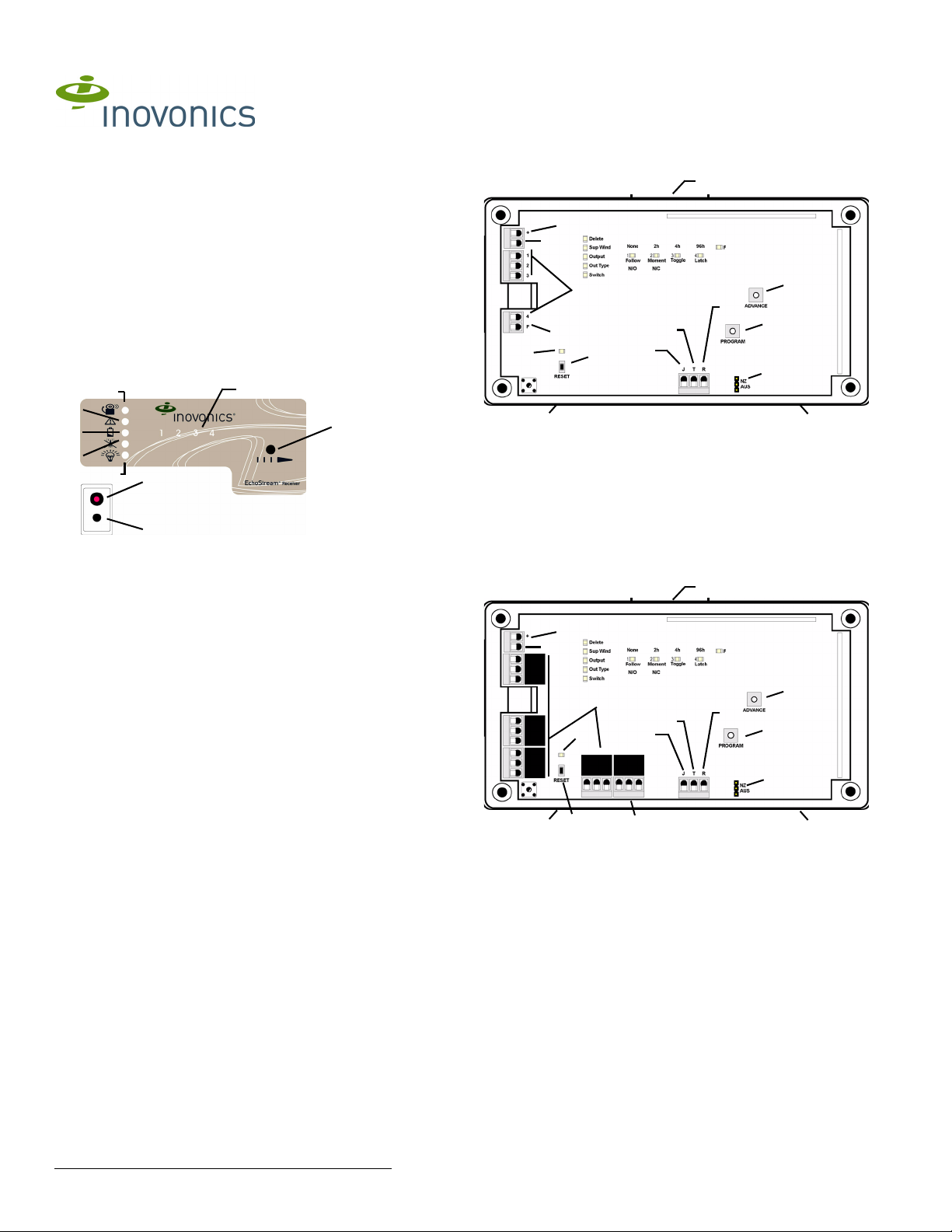
Figure 2 EN4204 Components
A Housing release
tabs
D Output terminals E Fault output F Advance button
G Reset button H Reset input I Jam output
J Tamper output K Program button L Frequency band selection
M Decode LED
B Power (11-14
VDC)
C Ground connection
pins
A
1.4 EN4204R Internal Components
A
B
C
D
M
J
I
H
F
K
L
G
A
Figure 3 EN4204R Components
A Housing release
tabs
D Output terminals E Fault output F Advance button
G Reset button H Reset input I Jam output
J Tamper output K Program button L Frequency band selection
M Decode LED
E
B Power (11-14
VDC)
A
C GND connection
pins
2 Installation and Startup
2.1 Connect Power Cabling
Before beginning startup, you will have to connect power to the receiver. To
connect power to the receiver:
1. Use a small screwdriver to press the housing release tab on the top or
bottom of the receiver; separate the housing.
2. Connect power cabling to the Power and GND connections.
• Power source should be 11-14 VDC. Power supply must be
unswitched, uninterrupted, and regulated.
© Inovonics, 2009 - www.inovonics.com
Page 2

2.2 Select the Frequency Band
EchoStream products are able to use a range of radio frequencies, and
must be configured for your geographic area. To configure the receiver:
1. Place a selection jumper on the appropriate frequency band selection
pins.
• Leave the jumper off the pins to set the frequency range to 902-928
MHz for North America.
• Place the jumper on the top two pins, marked NZ, to set the frequency
range to 921-928 MHz for New Zealand.
• Place the jumper on the bottom two pins, marked AUS, to set the
frequency range to 915-928 MHz for Australia.
Note: North American is also selected when the jumper is only attached to
one pin. This can prevent the jumper from being lost when selecting North
America.
2. Cycle power source to reset.
2.3 Program the Receiver
Note: If changing programming for a point that already has a transmitter
registered to it, there is no need to re-register the transmitter. Changes to
point programming are automatically assigned to the transmitter registered
to that point.
The default settings are:
Point Supervision
Window
1 4 hours 1 Follow N/O
2 4 hours 2 Follow N/O
3 4 hours 3 Follow N/O
4 4 hours 4 Follow N/O
F N/A Fault Inactive is set to follow; low
To program any of the four transmitter points or the fault output:
1. Use a small screwdriver to press the housing release tab on either side
of the receiver; separate the housing.
2. Use the Advance button to select any of the four transmitter points or
the fault output (Fig. 4).:
Delete
Sup Wind
Output
Out Type
Switch
Figure 4 Select the Output to Program
Note: The only programmable parameter on the fault output is whether the
output is normally opened or normally closed. If F is selected on an
EN4204, the EN4204 automatically advances to the switch option; an
EN4204R will not advance.
3. Press the Program button to begin programming the point. If no
transmitter has been registered to the chosen point, the receiver
advances to the supervision window option.
Note: If a transmitter has already been registered to the chosen point, the
Delete LED lights. Press Advance to delete the point and return to normal
operation; press Program to advance to the supervision window option.
4. Use the Advance button to choose a supervision window of None, 2h,
4h and 96h. Press Program to complete and advance to the output
option (Fig. 5).
Delete
Sup Wind
Output
Out Type
Switch
Figure 5 Select the Supervision Window
Output Type Switch
battery and tamper are set
to latching.
4h
None
1234
Follow
N/O
None
1234
Follow
N/O
2h
Moment
N/C
2h
Moment
N/C
Toggle
Toggle
96h
Latch
4h
96h
Latch
F
F
(EN4204
Only)
N/O
5. Use the Advance button to select the output number (Fig. 6). Press
Program to complete and advance to output type option.
Delete
Sup W ind
Output
Out Type
Switch
Figure 6 Select the Output Number
6. Use the Advance button to select the output type (Fig. 7). There are
four output types:
Follower: The output reflects the transmitter’s alarm status.
Momentary: The output turns on for seven seconds, then turns off,
regardless of the device status.
Toggle: The output changes state each time the device sends a new
activation. A minimum of four seconds must elapse before the output can
send a new activation.
Latching: The output turns on when activated and remains on until the
receiver is reset.
Delete
Sup W ind
Output
Out Type
Switch
Figure 7 Select the Output Type
Press Program to complete and advance to the switch type option.
7. Use the Advance button to choose between N/O and N/C (Fig. 8).
None
1234
Follow
N/O
None
1234
Follow
N/O
2h
Moment
N/C
2h
Moment
N/C
Toggle
Toggle
96h
4h
Latch
4h
96h
Latch
F
F
Press Program to complete..
Delete
Sup W ind
Output
Out Type
Switch
None
1234
Follow
N/O
2h
Moment
N/C
Toggle
96h
4h
Latch
F
Figure 8 Select the Switch Type
8. All the option LEDs will light and the point you’ve just programmed will
flash. If you wish to register a transmitter to the point you’ve just
programmed, press the transmitter’s Reset button; otherwise, press
Program to save programming changes without registering a
transmitter.
Note: All of the alert LEDs will turn off when the receiver has received the
transmitter’s registration message, and the point number LED will light for
two seconds. The registration is not complete until all LEDs turn off and the
point number lights, indicating the receiver has received the transmitter’s
registration message. If this does not occur, press Reset on the transmitter
again.
2.4 Factory Config
The factory config option is used to restore the EN4204 to it factory
defaults.
Caution: The factory config will erase all programmed point, output, and
language information.
To restore the factory configuration defaults to the EN4204:
1. Hold down the Reset and Advance buttons.
2. With the buttons held down, cycle EN4204 power.
3 Connect Input/Output Cabling
1. Connect cabling to the tamper output.
• The optional tamper output is a normally open (N/O) output that
reports receiver case tamper to an external device.
2. Connect cabling to the jam output.
• The optional jam output is a normally closed (N/C) output that opens
when noise thresholds on all transmission channels remain above a
predetermined value for any 30 seconds in any 60 second window.
The jam output is is set to the follow output type.
3. Connect cabling to the reset input.
• The optional reset input circuit permits installation of a remote
momentary normally open (N/O) switch to clear faults, unlatch outputs
and reset the receiver to a normal state.
4. Connect cabling to the output terminals.
5. Close receiver housing.
© Inovonics, 2009 - www.inovonics.com 2
Page 3

Vs
Ground
Output 1
Output 2
Output 3
Output 4
Fault
Figure 9 EN4204 Terminals
Vs
Ground
NC
COM
NO
NC
COM
NO
NC
COM
NO
Caution: Incorrect
connections may
cause damage to the
unit
Caution: Incorrect
connections may
cause damage to the
unit
NC
COMNONC
COM
NO
Jam output
Jam output
Tamper output
Tamper output
Reset input
Reset input
5 Warranty/Disclaimer
Caution: Changes or modifications to this unit not expressly approved by
Inovonics Wireless Corporation may void the installer's authority to operate
the equipment as well as the product warranty.
Inovonics Wireless Corporation ("Inovonics") warrants its products
("Product" or "Products") to conform to its own specifications and to be free
of defects in materials and workmanship under normal use for a period of
thirty-six (36) months from the date of manufacture. Within the warranty
period, Inovonics will repair or replace, at its option, all or any part of the
warranted Product. Inovonics will not be responsible for dismantling and/or
reinstallation charges. To exercise the warranty, the User ("User", "Installer"
or "Consumer") must work directly through their authorized distributor who
will be given a Return Material Authorization ("RMA") number by Inovonics.
Details of shipment will be arranged directly through the authorized
distributor.
This warranty is void in cases of improper installation, misuse, failure to
follow installation and operating instructions, alteration, accident or
tampering, and repair by anyone other than Inovonics.
This warranty is exclusive and expressly in lieu of all other warranties,
obligations or liabilities, whether written, oral, express, or implied. There is
no warranty by Inovonics that Inovonics product will be merchantable or fit
for any particular purpose, nor is there any other warranty, expressed or
implied, except as such is expressly set forth herein. In no event shall
Inovonics be liable for an incidental, consequential, indirect, special, or
exemplary damages, including but not limited to loss of profit, revenue, or
contract, loss of use, cost of down time, or interruption of business, nor any
claim made by distributor's customers or any other person or entity.
This warranty will not be modified or extended. Inovonics does not
authorize any person to act on its behalf to modify or extend this warranty.
This warranty will apply only to Inovonics Products. Inovonics will not be
liable for any direct, incidental, or consequential damage or loss
whatsoever, caused by the malfunction of Product due to products,
accessories, or attachments of other manufacturers, including batteries,
used in conjunction with Inovonics Products.
Note: E-mail support@inovonics.com for a copy of the CE Declaration of
Conformity.
Figure 10 EN4204R Terminals
3.1 Mount the Receiver
Caution: Mount the receiver in a location removed from metal. Metal
objects (duct work, wire mesh screens, boxes) will reduce RF range.
1. Use the provided anchors and screws to mount the receiver in a
location accessible for future maintenance.
2. Perform a walk test, activating each transmitter assigned to the receiver
and ensuring an appopriate response.
4 Specifications
Housing: 6.38" x 3.60" x 1.10" (162 mm x 92 mm x 28 mm)
Operating environment: 32°- 140°F (0°- 60°C), 90% relative humidity,
non-condensing
Power requirement: 11 - 14 VDC; 150 mA (EN4204), ~400 mA max
(EN4204R with all five relays energized)
Current consumption: Approx. 135 mA; approx. ~400 mA max (EN4204R
with all five relays energized)
Output specifications: Open collector, drive down to .4V @ 100 mA
(EN4204); Form C relay 1A @ 28 VDC, 0.5A @ 30 VAC resistive load
(EN4204R); N/O receiver case tamper contact closure, N/C receiver jam
output indication.
Input specifications: A low is less than .5 V; a high is greater than 2.5 V.
Reset input: Contact closure, momentary low.
Receiver type: Frequency hopping spread spectrum
Number of points/transmitters: Four
Number of alarm outputs: EN4204: four open collector outputs;
EN4204R: four Form C relay outputs
Number of fault outputs: EN4204: one open collector output; EN4204R:
one Form C relay outputs
Tam per
Reset
GND
GND
Jam
GND
Figure 11 Tamper, Reset and Jam Circuits
© Inovonics, 2009 - www.inovonics.com 3
 Loading...