

Page 1
ES1265 EchoStream® 360° Passive InfraRed Motion
Ceiling - 3 m (10 ft)
Effective Detection Diameter
14 m (46 ft)
0.8 M (2.6 Ft)
Floor
Detector
Installation and Operation Manual - 04098C
1 Overview
The ES1265 is a wireless, ceiling-mounted four-element passive infrared
(PIR) intrusion detector providing protection from intruders by pyrosensor array. Micro-controller signal analysis with special technology for
pulse processing increases immunity to interference, vibration, static,
lightning, ambient temperature changes and other common causes of
false alarms.
1.1 Inovonics Wireless Contact Information
If you have any problems with this procedure, contact Inovonics Wireless
technical services:
• E-mail: support@inovonics.com
• Phone: (800) 782-2709; (303) 939-9336
2 Installation and Startup
2.1 Install the Battery
Before installing the ES1265 you will need to install the battery. To
install the battery:
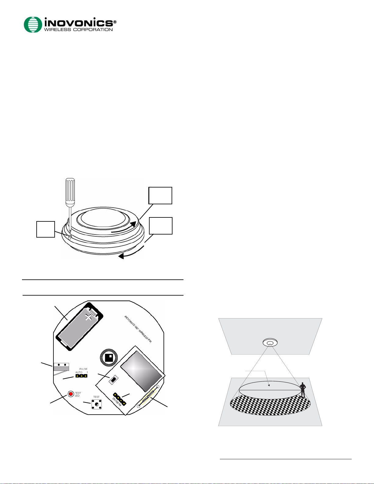
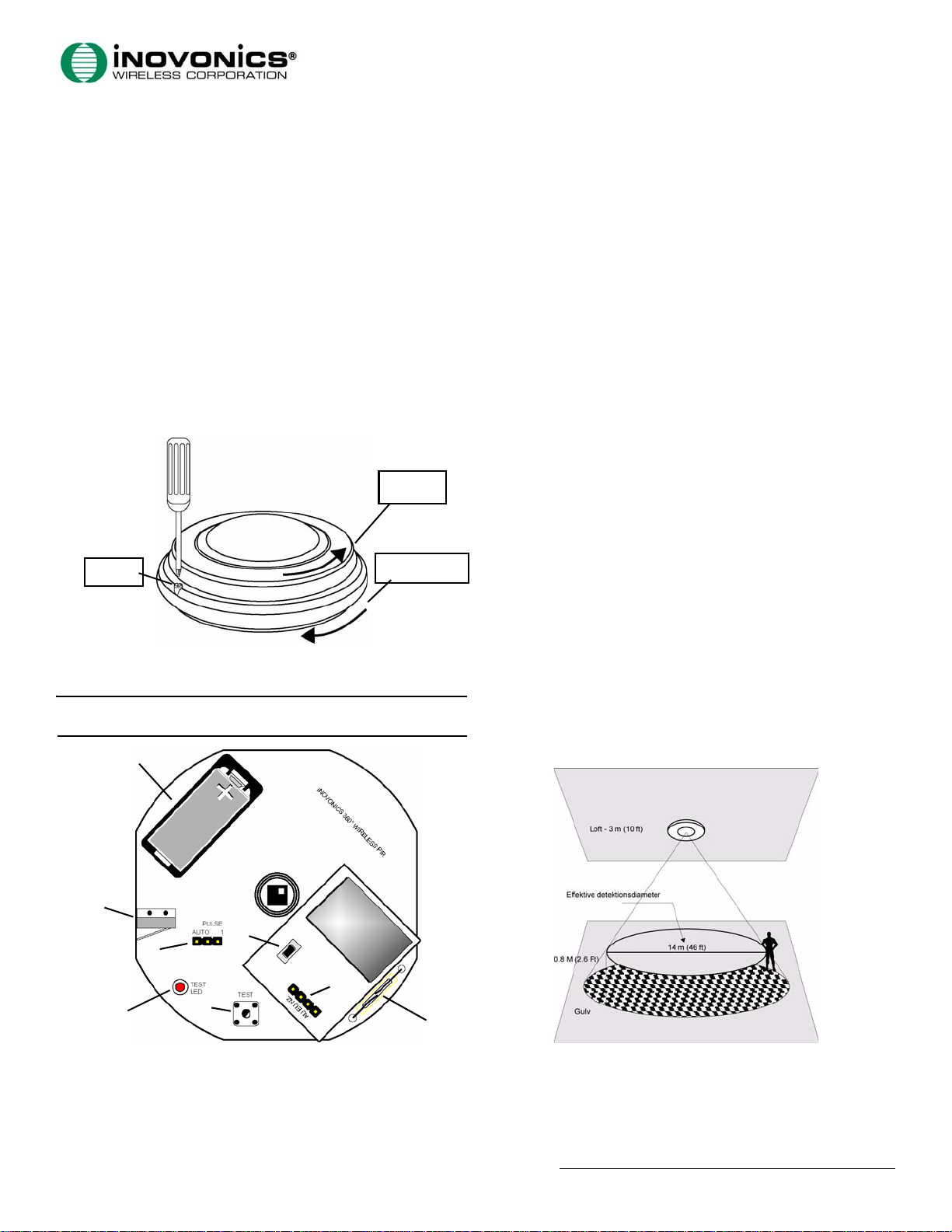
1. Loosen the housing lock screw (Fig. 1).
Remove the
Housing
Cover
Housing
Lock
Screw
Figure 1
Remove the Housing Cover and Mounting Bracket
2. Install the battery (Fig 2).
3. Press the Reset button to initialize the transmitter.
Note: You must press the Reset button each time the battery is
changed.
A
Remove the
Mounting
Bracket
G. Frequency selection
H. Walk test reed switch
pins
2.2 Select Frequency Band
EchoStream products are able to use a range of radio frequencies, and
must be configured for your geographic area:
1. Place a selection jumper on the appropriate frequency band selection
pins (Fig. 2).
• Place the jumper on the left two pins to select 921-928 MHz for
New Zealand.
• Place the jumper on the middle two pins to select 868-869 MHz for
Europe.
• Place the jumper on the right two pins to select 915-928 MHz for
Australia.
• Leave the jumper off the pins to select 902-928 MHz for North
America.
2.3 Select PIR Sensitivity
The pulse count selection pins provide control for difficult operating
environments. Automatic pulse count is recommended for reliable
operation in environments subject to temperature fluctuation that can
cause false alarms. The single pulse count mode is more sensitive to
minor temperature variations, and should be used in sites where variant
heat sources will not cause alarms. To select PIR sensitivity:
1. Place a selection jumper on the appropriate pulse count selection pins
(Fig. 1).
• Place the jumper on the left two pins to select an automatic pulse
count.
• Place the jumper on the right two pins to select a single pulse
count.
2.4 Register the PIR
The ES1265 must be registered. Refer to receiver, network coordinator or
control panel installation instructions to register the ES1265. Press Reset
when prompted to register the transmitter.
2.5 Mount the ES1265
1. Install the housing cover (Fig. 1).
2. Remove the mounting bracket (Fig. 1).
3. Use the provided anchors and screws to mount the ES1265 housing
base to the ceiling.
• The ES1265 can be mounted to a maximum height of approximately
18 feet (5.5 meters). At 18', the PIR detection pattern is about twice
the diameter of a 10' (3m) installation. As mounting height increases,
distance between detection zones also increases toward the perimeter,
and the effects of factors such as floor surface temperature and
intruder direction and speed are intensified. This can contribute to
reducing speed of detection. Every installation should include a walk
test of detection zones, including intrusion paths crossing the edges
of the zones. See Figure 3 and Figure 4 for more information.
B
E
C
G
D
Figure 2
A. Battery B. Tamper switch C. Pulse count
ES1265 Components
F
selection pins
D. Test LED E. Reset button F. Test button
H
Figure 3
ES1265 Detection Diameter
© 2006 Inovonics Wireless - www.inovonicswireless.com
Page 2
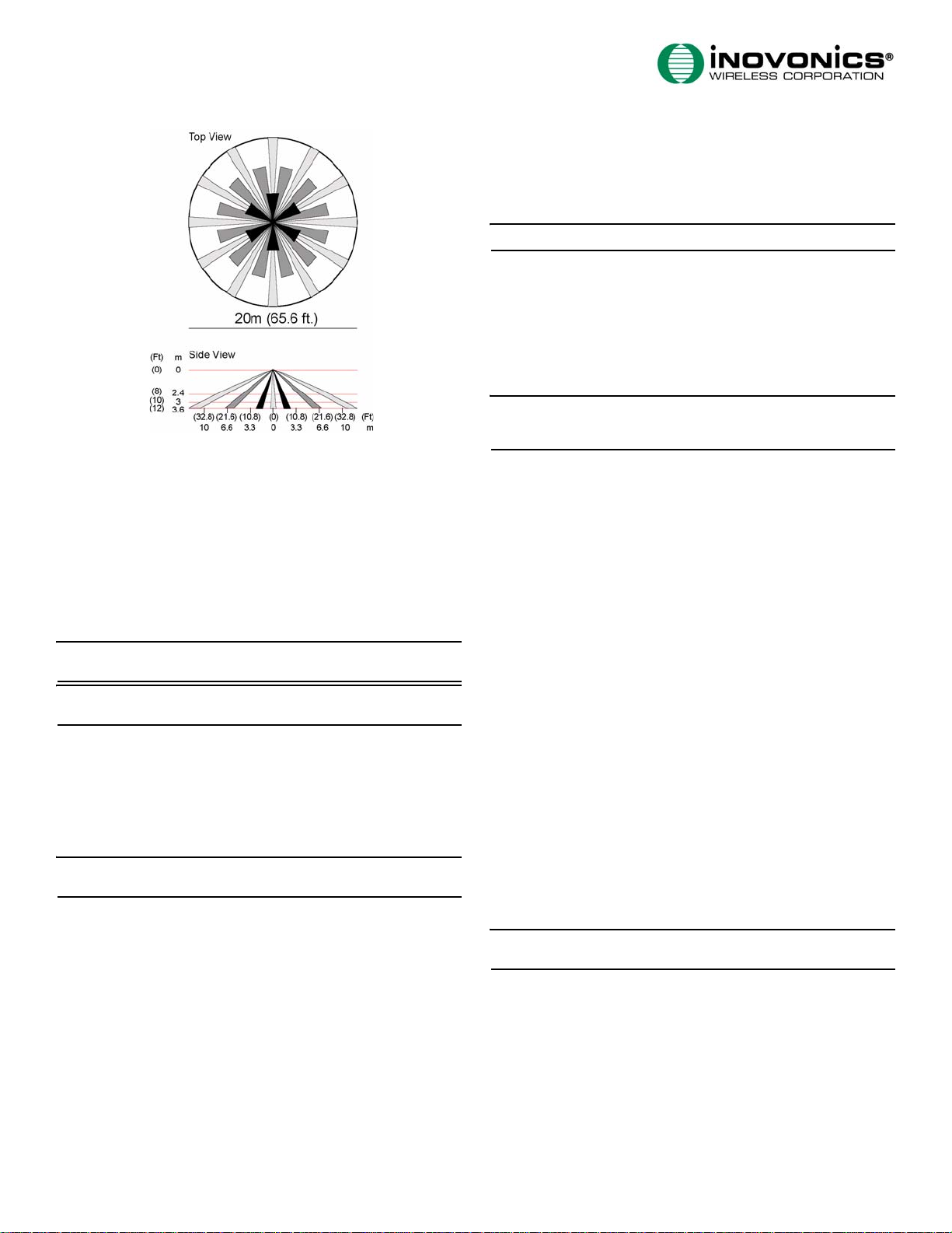
Figure 4 ES1265 Lens Pattern
4. When the housing base has been attached to the ceiling, install the
PIR on the mounting bracket.
3 T est the ES1265
3.1 Walk Test
When in walk test mode the test LED will light every time the ES1265
senses motion. The unit will not transmit alarm signals during this test
period. There are two ways to initiate a walk test. Once initiated, the
walk test will last for one minute. To initiate a walk test:
1. With the cover on the unit, pass a magnet near the walk test reed
switch for less than ½ of one second, or press the test button for less
than ½ second.
Note: With the cover on, the reed switch is located on the opposite
side of the ES1265 as the housing screw (Fig 2).
Note: The test LED only lights during the walk test and the
transmission test.
3.2 Transmission Test
When in transmission test mode the unit will transmit alarm and
restoral cycles at regular intervals for approximately one minute. The
LED will light every time the unit transmits. To initiate a transmission
test:
1. With the cover on the unit, hold a magnet near the walk test reed
switch for at least one second, or press the test button for at least one
second.
Note: With the cover on, the reed switch is located on the opposite
side of the ES1265 as the housing screw (Fig 2).
4 Operation
The ES1265 signals an alarm condition when motion is detected by the
sensor. Once an alarm is signaled, further alarms are suppressed until no
motion is detected for a period of four minutes.
The ES1265 contains a tamper switch on the board (Fig. 2) to alert the
user if the housing cover is removed. The ES1265 also contains tamper
contacts in the mounting bracket to alert the user if the unit is removed
from the wall.
5 Specifications
Dimensions: 5.2" x 2.25" (131mm x 57mm)
Weight: 6.52 oz. (185g)
Detection method: 4-element PIR
Operating temperature: 32°F to 120°F (0°C to 49°C)
Humidity: 10% to 90% non-condensing
Battery: Inovonics BAT604 (3.0V lithium Duracell DL123A)
Note: Battery is supervised
Typical battery life: 2 years in location with low to moderate activity
Visible light protection: Stable against halogen light 8 feet (2.4m)
or reflected light
Temperature compensation: Yes
Pulse count: Selectable single pulse or multiple pulse
Frequency: 868-869 MHz (Europe), 915-928 MHz (Australia), 921-928
MHz (New Zealand), 902-928 MHz (USA)
6 Warranty/Disclaimer
Caution: Changes or modifications to this unit not expressly approved
by Inovonics Wireless Corporation may void the installer's authority to
operate the equipment as well as the product warranty.
Inovonics Wireless Corporation ("Inovonics") warrants its products
("Product" or "Products") to conform to its own specifications and to be
free of defects in materials and workmanship under normal use for a
period of twenty-four (24) months from the date of manufacture. Within
the warranty period, Inovonics will repair or replace, at its option, all or
any part of the warranted Product. Inovonics will not be responsible for
dismantling and/or reinstallation charges. To exercise the warranty, the
User ("User", "Installer" or "Consumer") must work directly through
their authorized distributor who will be given a Return Material
Authorization ("RMA") number by Inovonics. Details of shipment will be
arranged directly through the authorized distributor.
This warranty is void in cases of improper installation, misuse, failure to
follow installation and operating instructions, alteration, accident or
tampering, and repair by anyone other than Inovonics.
This warranty is exclusive and expressly in lieu of all other warranties,
obligations or liabilities, whether written, oral, express, or implied.
There is no warranty by Inovonics that Inovonics product will be
merchantable or fit for any particular purpose, nor is there any other
warranty, expressed or implied, except as such is expressly set forth
herein. In no event shall Inovonics be liable for an incidental,
consequential, indirect, special, or exemplary damages, including but
not limited to loss of profit, revenue, or contract, loss of use, cost of
down time, or interruption of business, nor any claim made by
distributor's customers or any other person or entity.
This warranty will not be modified or extended. Inovonics does not
authorize any person to act on its behalf to modify or extend this
warranty.
This warranty will apply only to Inovonics Products. Inovonics will not
be liable for any direct, incidental, or consequential damage or loss
whatsoever, caused by the malfunction of Product due to products,
accessories, or attachments of other manufacturers, including batteries,
used in conjunction with Inovonics Products.
Note: E-mail support@inovonics.com for a copy of the CE Declaration
of Conformity.
Page 3
ES1265 EchoStream® 360° PIR-detektor
Installations- og betjeningsmanual - 04098C
1 Oversigt
ES1265 er en trådløs, loftmonteret, passiv infrarød indbrudsdetektor
(PIR), med QUAD. Microcontrollerens analyse af signalerne, ved hjælp af
en særlig teknologi til pulsbehandling, forøger immuniteten overfor
interferens, vibration, statisk elektricitet, belysning, ændringer i
omgivelsernes temperatur, og andre almindelige årsager til falske
alarmer.
1.1 Kontaktoplysninger
Kontakt den tekniske support hos Alarm System A/S, hvis du har
problemer at installere ES1265:
• E-mail: support@inovonics.com
• Telefon: (800) 782-2709; (303) 939-9336
2 Installation og ibrugtagning
2.1 Montering af batteriet
Inden installering af ES1265, er det nødvendigt at montere batteriet.
Sådan monteres batteriet:
1. Løsn husets låseskrue (Fig. 1).
Fjern husets
dæksel
Husets
låseskrue
Figure 1
Tag husets dæksel og monteringsbeslag af
2. Sæt batteriet i (Fig 2).
3. Tryk på Reset-knappen for at initialisere senderen.
Bemærk: Du skal trykke på Reset knappen, hver gang batteriet
udskiftes.
A
Fjern
monteringsbeslaget
2.2 Valg af frekvensbånd
EchoStream-produkterne er i stand til at benytte en række af
radiofrekvenser, og skal konfigureres til dit geografiske område:
1. Placér en jumper på det ønskede frekvensbånds pins (Fig. 2).
• Placér jumperen på de to pins til venstre, for at vælge 921-928 MHz
i New Zealand.
• Placér jumperen på de to pins i midten, for at vælge 868-869 MHz i
Europa.
• Placér jumperen på de to pins til højre, for at vælge 915-928 MHz i
Australien.
• Undlad at sætte jumperen på, for at vælge 902-928 MHz i
Nordamerika.
2.3 Valg af PIR-følsomhed
Pins´ene til valg af pulstæller giver styring i vanskelige driftsmiljøer. Det
anbefales at bruge automatisk pulstælling, for at få en driftsikker
funktion i miljøer, som er udsat for temperatursvingninger, der kan
forårsage falske alarmer. Tilstanden med reaktion på enkeltpuls er mere
følsom overfor mindre temperatursvingninger - og bør anvendes på
steder, hvor forskellige varmekilder ikke vil forårsage alarmer. Sådan
vælges PIR´ens følsomhed:
1. Placér en jumper på de ønskede pulstæller-pins (Fig. 1).
• Placér jumperen på de to pins til venstre, for at vælge automatisk
pulstælling.
• Placér jumperen på de to pins til højre, for at vælge reaktion på
enkelt puls.
2.4 Registrering af PIR´en
ES1265 skal registreres. Se i installationsanvisningerne til modtageren,
netværkskoordinatoren eller kontrolpanelet, for at registrere ES1265.
Tryk på Reset, når du bliver bedt om at registrere senderen.
2.5 Montering af ES1265
1. Sæt husets afskærmning på (Fig. 1).
2. Fjern monteringsbeslaget (Fig. 1).
3. Brug de medfølgende rawlplugs og skruer til at montere ES1265 husets
bund i loftet.
• ES1265 kan monteres i en højde på maksimalt 5,5 meter. Ved 5,5
meters højde er detektionsområdets diameter cirka dobbelt så stort
som diameteren for en installation i 3 meters højde. I takt med at
monteringshøjden forøges, øges også afstanden mellem detektionszonerne - og effekten af faktorer som gulvoverfladens temperatur og
den indtrængende persons retning og hastighed bliver større. Dette
kan bidrage til at reducere detektionshastigheden. Enhver installation
skal inkludere en gang-test af detektionszonerne, inklusive
indbrudsveje henover zonernes kanter. Se Figur 3 og Figur 4 for
yderligere oplysninger.
B
E
C
G
D
Figure 2
ES1265 Komponenter
F
H
A. Batteri B. Sabotageknap C. Pins til valg af
pulstælling
D. Test-LED E. Reset-knap F. Test-knap
G. Pins til valg af
H. Gang-test knap
frekvens
Figure 3
ES1265 Detektionsdiameter
© 2006 Inovonics Wireless - www.inovonicswireless.com
Page 4
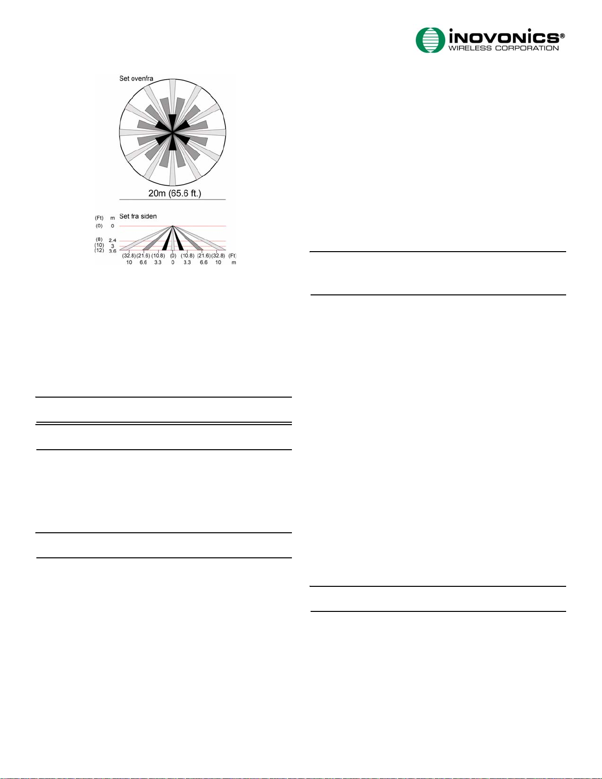
Figure 4 ES1265 Linsemønster
4. Når husets bund er blevet fastgjort til loftet, installeres PIR-
detektoren på monteringsbeslaget.
3 Afprøvning af ES1265
3.1 Gang-test
Når den er i gang-test mode, vil test-LED´en lyse, hver gang ES1265
opdager en bevægelse. Enheden vil ikke sende alarmsignaler i denne
testperiode. Der er to måder at starte en gang-test på. Når den er
startet, vil gang-testen vare i ét minut. Sådan indledes en gang-test:
1. Med dækslet på enheden føres en magnet tæt forbi gang-test
knappen - i mindre end ½ sekund, eller der trykkes på test-knappen i
mindre end ½ sekund.
Bemærk: Med dækslet på, er knappen placeret på den modsatte side
af ES1265, i forhold til husets skrue (Fig 2).
Bemærk: Test-LED´en lyser kun under gang-testen og
transmissionstesten.
3.2 Transmissionstest
Når den er i transmissionstest mode, vil enheden sende alarm- og
ReStore cyklusser med regelmæssige intervaller i omkring ét minut.
LED´en vil lyse, hver gang enheden sender. Sådan indledes en
transmissionstest:
1. Med dækslet på enheden holdes en magnet tæt på gang-test knappen
- i mindst 1 sekund, eller der trykkes på test-knappen i mindst 1
sekund.
Bemærk: Med dækslet på, er knappen placeret på den modsatte side
af ES1265, i forhold til husets skrue (Fig 2).
4 Betjening
ES1265 signalerer en alarmtilstand når en bevægelse opdages af
sensoren. Så snart der signaleres en alarm, undertrykkes yderligere
alarmer, indtil der ikke opdages nogen bevægelser i en periode på fire
minutter.
ES1265´eren har en sabotageknap på pladen (Fig. 2), for at alarmere
brugeren hvis husets afskærmning fjernes. ES1265 indeholder også
sabotagekontakter i monteringsbeslaget, for at alarmere brugeren hvis
enheden fjernes fra væggen.
5 Specifikationer
Dimensioner: 131mm x 57mm
Vægt: 185 g
Detektionsmetode: PIR med QUAD
Driftstemperatur: 0°C til 49°C
Fugtighed: 10% til 90% R.F.- ikke kondenserende
Batteri: Inovonics BAT604 (3,0V Lithium Duracell DL123A)
Bemærk: Batteriet overvåges
Typisk levetid for batteri: 2 år - på et sted med lav til moderat
aktivitet
Beskyttelse mod synligt lys: Stabil ved halogenlys, 2,4m - eller
reflekteret lys
Temperaturkompensation: Ja
Pulstælling: Der kan vælges enkeltpuls eller flere pulser
Frekvens: 868-869 MHz (Europa), 915-928 MHz (Australien), 921-928
MHz (New Zealand), 902-928 MHz (USA)
6 Garanti / Forbehold
Caution: Der må ikke uden forudgående, skriftlig godkendelse fra
Inovonics Wireless Corporation foretages ændringer i dette produkt.
Enhver ændring vil medføre, at garantien og reklamationsretten
bortfalder.
Inovonics Wireless Corporation ("Inovonics") garanterer, at alle firmaets
produkter overholder de oplyste specifikationer - og at produkterne
garanteres at fungere fejlfrit i 24 måneder fra produktionsdatoen under forudsætning af normal anvendelse i normalt miljø. I den 24
måneders garantiperiode kan Inovonics efter eget valg reparere eller
udskifte hele produktet eller dele deraf. Inovonics kan ikke holdes
ansvarlig for afmontering og/eller genmontering - dette sker for
installatørens egen regning. I tilfælde af, at brugeren/installatøren
ønsker at anvende produktets garanti, skal Alarm System A/S kontaktes.
Inovonics udsteder en tilladelse til returnering til Alarm System A/S (en
RMA). Detaljer om emballering, oplysninger om den konstaterede fejl
samt forsendelse skal aftales med Alarm System A/S. Denne garanti
bortfalder i tilfælde af forkert installation, misbrug, udendørs
montering - samt i tilfælde, hvor brugermanualens og/eller
installationsmanualens bestemmelser og anvisninger ikke er overholdt.
Konstruktionsmæssige ændringer, hærværk eller sabotage samt enhver
form for reparation udført af andre end Inovonics eller Alarm System A/
S medfører ligeledes, at garantien bortfalder.
Denne garanti erstatter alle andre garantier - mundtlige såvel som
skriftlige. Inovonics kan ikke garantere, at produkterne i enhver
situation passer til applikationen. Inovonics kan under ingen
omstændigheder holdes ansvarlig for følgevirkninger som tabt tid, tabt
avance, forstyrrelser i driften på installationsstedet eller lignende hverken fra installatører eller fra slutbrugere.
Denne garanti vil hverken blive ændret eller udvidet. Inovonics vil ikke
tillade, at andre på vegne af Inovonics ændrer eller udvider denne
garanti.
Denne garanti omfatter udelukkende Inovonics' produkter. Inovonics
kan ikke holdes ansvarlig for tab eller forstyrrelser forårsaget af tilbehør
eller tilkoblede produkter fra andre leverandører - dette forbehold
omfatter bl.a. de benyttede batterier.
Bemærk: Send en e-mail til: info@alarmsystem.dk hvis du ønsker en
kopi af CE-certifikatet tilsendt.
Page 5

Détecteur de mouvement passif à infrarouges sur 360°
®
EchoStream
ES1265
Manuel d'installation et d'utilisation - 04098C
1 Vue d'ensemble
Le détecteur ES1265 est un détecteur d'intrusion (PIR) passif à
infrarouges composé de quatre éléments, à installer au plafond, afin de
détecter la présence d'intrus. L'analyse des signaux du microcontrôleur
équipé d'une technologie spéciale pour le traitement des impulsions
augmente l'immunité aux perturbations, aux vibrations, à l'électricité
statique, à l'éclairage, aux variations de la température ambiante et
autres causes courantes de fausses alarmes.
1.1 Informations de contact de Inovonics Wireless
Pour tout problème avec cette procédure, veuillez contacter les services
techniques de Inovonics Wireless :
• E-mail : support@inovonics.com
• Téléphone : (800) 782-2709; (303) 939-9336
2 Installation et démarrage
2.1 Installation de la pile
Avant d'installer le détecteur ES1247, vous devez installer la pile. Pour
installer la pile :
1. Dévissez la vis de fixation du boîtier (Fig. 1).
Retirez le
couvercle du
Boîtier.
Vis de
fixation du
Boîtier
Figure 1 Enlevez le couvercle du boîtier et le support de fixation.
2.
Installez la pile (Fig. 2).
3. Appuyez sur le bouton Reset (réinitialiser) de l'émetteur.
Remarque : Vous devez appuyer sur le bouton Reset chaque fois que la
pile est remplacée.
A
B
Enlevez le
support de
fixation.
G. Broches de
sélection des
H. Contacteur en ampoule
du test de fonctionnement
fréquences
2.2 Sélection de la bande de fréquence
Les produits EchoStream peuvent utiliser une large gamme de
radiofréquences et doivent être configurés selon votre zone
géographique.
1. Placez un cavalier sur les broches de sélection de la bande de
fréquences appropriée (Fig. 2).
• Placez le cavalier sur les deux broches gauches pour sélectionner
921-928 MHz (Nouvelle-Zélande).
• Placez le cavalier sur les deux broches centrales pour sélectionner
868-869 MHz (Europe).
• Placez le cavalier sur les deux broches droites pour sélectionner
915-928 MHz (Australie).
• Laissez les broches sans cavalier pour sélectionner 902-928 MHz
(Amérique du Nord).
2.3 Sélection de la sensibilité du PIR
Les broches de sélection pour le décompte des impulsions permettent de
contrôler les environnements pénibles. Le décompte automatique des
impulsions est recommandé pour un fonctionnement fiable dans un
milieu soumis à des variations de température capables de provoquer des
fausses alertes. Le mode de décompte simple des impulsions est plus
sensible aux faibles variations de température. Utilisez-le dans les zones
où aucune source de chaleur ne peut provoquer des alarmes. Pour
sélectionner la sensibilité du PIR :
1. Placez un cavalier sur les broches de sélection appropriées du
décompte des impulsions (Fig.1).
• Placez le cavalier sur les deux broches gauches pour sélectionner un
décompte automatique.
• Placez le cavalier sur les deux broches droites pour sélectionner un
décompte simple.
2.4 Enregistrement du PIR
Le ES1265 doit être enregistré. Consultez les instructions d'installation
du récepteur, du coordonnateur réseau ou du panneau de commande
pour enregistrer l'émetteur ES1265. Appuyez sur Reset quand vous y êtes
invité pour enregistrer l'émetteur.
2.5 Installation du détecteur ES1265
1. Installez le couvercle du boîtier (Fig. 1).
2. Enlevez le support de fixation (Fig. 1).
3. Utilisez les points d'attache et les vis fournis pour fixer la base du
boîtier ES1265 au plafond.
• Le ES1265 peut être monté à une hauteur maximale d'environ 5,5
mètres. A 5,5 mètres, la zone de détection du PIR correspond environ
à deux fois le diamètre d'une installation à 3m. En augmentant la
hauteur de fixation, la distance entre les zones de détection
augmente également par rapport à la zone à surveiller. L'effet de
plusieurs facteurs, comme la température de la surface du sol et le
sens et la vitesse de déplacement de l'intrus, est intensifié. Cet effet
peut diminuer la vitesse de détection. Chaque installation doit inclure
un test de fonctionnement des zones de détection, notamment des
voies d'intrusion au bord des zones. Consultez les Figures 3 et 4 pour
obtenir des informations complémentaires.
E
C
D
Figure 2 Composants du ES1265
A.
Pile B. Contacteur anti-
F
sabotage
D. DEL de test E. Bouton de
réinitialisation
G
H
C. Broches de
sélection pour le
décompte des
impulsions
F. Bouton de test
Figure 3 Diamètre de détection du ES1265
© 2006 Inovonics Wireless - www.inovonicswireless.com
Page 6

Figure 4 Zone de la lentille ES1265
4. Quand la base du boîtier a été fixée au plafond, installez le PIR sur le
support de fixation.
3 Test du détecteur ES1265
3.1 Test de fonctionnement
Pendant le test de fonctionnement, la DEL s'allume dès que le ES1265
détecte un mouvement. L'unité ne transmet aucun signal d'alarme
pendant ce test. Il existe deux méthodes pour lancer un test de
fonctionnement. Dès qu'il est lancé, le test de fonctionnement dure
une minute. Pour lancer un test de fonctionnement :
1. Le couvercle étant sur l'unité, passez un aimant prés du contacteur
en ampoule du test de fonctionnement pendant moins d'une demie
seconde, ou appuyez sur le bouton de test pendant moins d'une demie
seconde.
Remarque : Le couvercle étant en place, le contacteur en ampoule est
situé sur le côté opposé du ES1265 tout comme la vis du boîtier (Fig.
2).
Remarque : La DEL de test s'allume uniquement pendant les tests de
fonctionnement et de transmission.
3.2 Test de transmission
Durant le test de transmission, l'unité transmet des cycles d'alerte et de
rétablissement à intervalles réguliers durant une minute environ. La
DEL s'allume chaque fois que l'unité transmet un signal. Pour lancer un
test de transmission :
1. Le couvercle étant sur l'unité, maintenez un aimant prés du
contacteur en ampoule du test de fonctionnement pendant au moins
une seconde, ou appuyez sur le bouton de test pendant au moins une
seconde.
Remarque : Le couvercle étant en place, le contacteur en ampoule est
situé sur le côté opposé du ES1265 tout comme la vis du boîtier (Fig.
2).
4 Fonctionnement
Le détecteur ES1265 émet une alarme dès qu'il détecte un mouvement.
Dès que l'alarme est signalée, les alarmes supplémentaires sont
supprimées jusqu'à ce qu'aucun mouvement ne soit détecté pendant
une période de quatre minutes.
La carte du ES1265 comprend un contacteur anti-sabotage (Fig. 2) pour
avertir l'utilisateur si le couvercle du boîtier est retiré. Des contacts
anti-sabotage sont également présents sur le support de fixation du
ES1265 pour avertir l'utilisateur quand l'unité est retirée du mur.
5 Spécifications
Dimensions : 131 mm x 57 mm
Poids : 185 g
Méthode de détection : PIR à 4 éléments
Température d'utilisation : 0°C à 49°C
Humidité : 10% à 90% sans condensation
Pile : Inovonics BAT604 (3,0V lithium Duracell DL123A)
Remarque : La pile est supervisée
Vie utile de la pile : 2 ans dans une zone présentant une activité
faible à modérée
Protection contre la lumière visible : Stable face à un éclairage
halogène ou une lumière réfléchie situé à 2,4m
Compensation de la température : Oui
Décompte des impulsions : Impulsion simple ou multiple, au choix
Fréquence : 868-869 MHz (Europe), 915-928 MHz (Australie), 921-
928 MHz (Nouvelle Zélande) 902-928 MHz (Etats-Unis)
6 Garantie/Clause de non responsabilité
Avertissement : Les changements ou les modifications à cette unité
non approuvés expressément par Inovonics Wireless Corporation
peuvent empêcher à l'installateur d'utiliser le matériel, ainsi qu'annuler
la garantie du produit.
Inovonics Wireless Corporation ("Inovonics") garantit que ses produits
("Produit" ou "Produits") sont conformes aux caractéristiques
indiquées et qu'ils ne présentent pas de défaut de matériel ou de maind'œuvre dans des conditions d'utilisation normale pendant une période
de vingt-quatre (24) mois à partir de la date de fabrication. Au cours de
la période de garantie, Inovonics réparera ou remplacera, à son choix,
la totalité ou une partie du Produit sous garantie. Inovonics ne sera
pas responsable des coûts de démontage et/ou de réinstallation. Pour
bénéficier de sa garantie, l'Utilisateur ("Utilisateur", "Installateur" où
"Consommateur") devra traiter directement avec son distributeur agréé
à qui Inovonics fournira un numéro d'autorisation de retour de matériel
("RMA"). L'organisation de l'envoi sera effectuée directement par le
biais du distributeur agréé.
Cette garantie est nulle dans le cas d'une installation incorrecte, d'une
mauvaise utilisation, d'un non respect des instructions d'installation et
d'opération, d'altérations, d'accidents ou d'anti-sabotages, et de
réparations par une personne extérieure au service aprés-vente
d'Inovonics. Cette garantie est exclusive et remplace expressément
toute autre garantie, obligation ou responsabilité, qu'elles soient
écrites, orales, explicites ou implicites. Inovonics ne fournit aucune
garantie sur le fait que le produit Inovonics sera commercialisable ou
adéquat pour une utilisation spécifique, ni ne fournit de garantie,
explicite ou implicite, autres que celles fournies expressément dans le
document ci-inclus. En aucun cas Inovonics ne sera responsable de
dommages accessoires, consécutifs, indirects, spéciaux ou moraux,
dont, entre autres, la perte de profits, revenus ou contrats, la perte
d'utilisation, les coûts de temps d'immobilisation ou d'interruption
d'activité, ni d'autres demandes d'indemnisation déposées par les
clients du distributeur ou par toute autre personne physique ou morale.
Cette garantie ne sera ni modifiée, ni étendue. Inovonics n'autorise
aucune personne à agir en son nom pour modifier ou étendre cette
garantie.
Cette garantie s'appliquera uniquement aux Produits Inovonics.
Inovonics ne sera pas responsable de toutes pertes ou dommages
directs, indirects ou consécutifs, quels qu'ils soient, causés par le
mauvais fonctionnement du Produit en raison de produits, accessoires
ou compléments d'autres fabricants, y compris les piles, utilisés
conjointement aux Produits Inovonics.
Remarque : écrire à support@inovonics.com pour obtenir une copie
de la déclaration de conformité CE.
Page 7

Sensore di movimento passivo a infrarossi ES1265
®
EchoStream
360°
Manuale d'installazione e uso - 04098C
1 Generalità
Il sensore ES1265 è un sensore di intrusione ad infrarossi (PIR), passivo,
a quattro elementi, installabile a soffitto, appositamente progettato per
proteggere contro le intrusioni (sensore PYRO). L'analisi dei segnali
attraverso il microcontrollore, con tecnologia speciale per il trattamento
dei impulsi, garantisce un'elevata immunità alle interferenze in
radiofrequenza , alle vibrazioni, alle correnti statici, ai fulmini, alle
variazioni di temperatura ambiente ed altri elementi che possono
causare allarmi fittizi.
1.1 Recapiti di Inovonics Wireless
Per eventuali dubbi o domande sulle operazioni descritte in questo
documento, rivolgersi al Servizio di assistenza tecnica di Inovonics
Wireless ai seguenti recapiti:
• E-mail: support@inovonics.com
• Telefono: (800) 782-2709; (303) 939-9336
2 Installazione e accensione
2.1 Montaggio della batteria
Prima di montare l'ES1265, installare la batteria. Per installare la
batteria:
1. Allentare la vite di fissaggio alloggiamento (Fig. 1).
Rimozione del
coperchio
dell'alloggiament
Vite di
fissaggio
alloggiamento
Figura 1
montaggio
Rimozione della coperchio dell'alloggiamento e della staffa di
2. Installare la batteria (Fig. 2).
3. Premere il pulsante Reset per inizializzare il trasmettitore.
Nota: dopo aver cambiato la batteria, va sempre premuto il pulsante
Reset.
A
Rimozione
della staffa di
montaggio
G. Pin selezione
frequenza
H. Interruttore a lamella test di rilevamento del
movimento
2.2 Selezione della banda di frequenza
I prodotti EchoStream sono in grado di servirsi di un campo di
radiofrequenze e vanno configurati appositamente per l'area geografica
di applicazione:
1. Posizionare un ponticello di selezione sui pin di selezione banda di
frequenza interessati (Fig. 2).
• Posizionare il ponticello sui due pin di sinistra per selezionare 921928 MHz per la Nuova Zelanda.
• Posizionare il ponticello sui due pin centrali per selezionare 868869 MHz per l'Europa.
• Posizionare il ponticello sui due pin di destra per selezionare 915928 MHz per l'Australia.
• Lasciare il ponticello fuori dai pin per selezionare 902-928 MHz per
l'America settentrionale.
2.3 Selezione della sensibilità PIR
I pin di selezione conteggio impulsi consentono di controllare il
ponticello per il conteggio degli impulsi consente di controllare gli
ambienti normali o complessi. Il conteggio impulsi automatico è
consigliato per il funzionamento affidato in condizioni ambientali
soggette variazioni di temperatura e quindi ad eventuali falsi allarmi. La
modalità a impulso singolo è più sensibile a variazioni di temperatura
minori e deve essere usata per locali in cui le variazioni delle fonti di
calore non causano allarmi. Per selezionare la sensibilità PIR:
1. Posizionare un ponticello di selezione sui pin di selezione conteggio
impulsi interessati (Fig. 1).
• Posizionare il ponticello sui due pin di sinistra per selezionare il
conteggio impulsi automatico.
• Posizionare il ponticello sui due pin di destra per selezionare il
conteggio impulsi singolo.
2.4 Registrazione del PIR
L'ES1247 va registrato. Per registrare il trasmettitore ES1265, consultare
il manuale del ricevitore, del coordinatore di rete o del pannello di
controllo. Dietro sollecito, premere il pulsante Reset per registrare il
trasmettitore.
2.5 Montaggio del sensore ES1265
1. Montare la copertura dell'alloggiamento (Fig. 1).
2. Rimuovere la staffa di montaggio (Fig. 1).
3. Per montare al soffitto la base di alloggiamento dell'ES1265, utilizzare
i dispositivi di ancoraggio e le viti fornite in dotazione.
• L'ES1265 può essere montato su un'altezza massima di circa 18
piedi (5.5 metri). A 18', la configurazione di rilevamento PIR è circa il
doppio del diametro di un'installazione di 10' (3 m). Coll'aumentare
dell'altezza di montaggio, aumenta altresì la distanza tra le zone di
rilevamento verso il perimetro e si accentuano gli effetti dei fattori
quali: temperatura superficie pavimento, velocità e direzione
dell'intruso. Ciò può contribuire a ridurre la rapidità di rilevamento.
Per ogni installazione va eseguito il test di rilevamento del movimento
all'interno delle zone di rilevamento, compresi i percorsi di intrusione
attraverso i confini delle zone. Per ulteriori informazioni, riferire alle
Figg. 3 e 4.
B
E
C
G
D
Figura 2
Componenti del sensore di movimento ES1265
A. Batteria B. Interruttore
F
antimanomissione
C. Pin selezione
conteggio impulsi
D. LED test E. Pulsante Reset F. Pulsante Test
H
Figura 3
Diametro di rilevamento del sensore di movimento ES1265
© 2006 Inovonics Wireless - www.inovonicswireless.com
Page 8

Figura 4 Configurazione della lente del sensore di movimento ES1265
4. Una volta fissata la base dell'alloggiamento al soffitto, installare il
PIR sul braccio di montaggio.
3 T est del sensore ES1265
3.1 Test di rilevamento del movimento
Nella modalità test di rilevamento del movimento, il LED test si accende
ogni volta che l'ES1265 rileva un movimento. Durante il test, l'unità
non deve trasmettere alcun segnale di allarme. Sono due i modi per
inizializzare il test di movimento. Una volta inizializzato, il test di
movimento dura 1 minuto. Per inizializzare il test di movimento:
1. Con il coperchio montato sull'unità, avvicinare un magnete
all'interruttore a lamella test di movimento per meno di ½ secondo o
premere il pulsante test per meno di ½ secondo.
Nota: con il coperchio montato, l'interruttore a lamella è ubicato sul
lato opposto dell'ES1265 come la vite dell'alloggiamento (Fig. 2).
Nota: il LED test si accende solo durante il test di rilevamento del
movimento e il test di trasmissione.
3.2 Test di trasmissione
Nella modalità del test di trasmissione, l'unità deve essere in grado di
trasmettere regolarmente segnali di allarme e di ripristino per circa 1
minuto. Il LED si illumina ogni volta che l'unità trasmette. Per
inizializzare il test di trasmissione:
1. Con il coperchio montato sull'unità, avvicinare un magnete
all'interruttore a lamella test di movimento per almeno 1 secondo o
premere il pulsante test per meno 1 secondo.
Nota: con il coperchio montato, l'interruttore a lamella è ubicato sul
lato opposto dell'ES1265 come la vite dell'alloggiamento (Fig. 2).
4 Funzionamento
L'ES1265 trasmette un segnale di allarme ogni volta che il sensore rileva
un movimento. Una volta segnalato un allarme, altri allarmi vengono
soppressi fin quando non viene più rilevato alcun movimento per un
periodo di 4 minuti.
L'ES1265 contiene un interruttore antimanomissione sulla scheda (Fig.
2) che avvisa l'utente qualora venga rimosso il coperchio
dell'alloggiamento. L'ES1265 contiene inoltre contatti
antimanomissione nella staffa di montaggio che avvisano l'utente
qualora l'unità venga rimossa dalla parete.
5 Dati tecnici
Dimensioni: 5.2 x 2.25" (131 x 57 mm)
Peso: 6.52 once (185g)
Metodo di rilevamento: PIR a 4 elementi
Temperatura di esercizio: da 0°C a 49°C (da 32°F a 120°F)
Umidità: 10 -90% (senza condensa)
Batteria: Inovonics BAT604 (al litio da 3 V Duracell DL123A)
Nota: la batteria è controllata.
Durata tipica della batteria: 2 anni per locali con livello di attività
medio
Protezione dalla luce visibile: Stabile contro luce alogena
(distanza di 8 piedi - 2.4 m) o luce riflessa
Compensazione termica: Sì
Conteggio impulsi: Possibilità di selezionare la modalità a impulsi
singoli o multipli
Frequenza: 868-869 MHz (Europa), 915-928 MHz (Australia), 921-928
MHz (Nuova Zelanda), 902-928 MHz (U.S.A.)
6 Clausola di garanzia
Attenzione: variazioni o modifiche non espressamente autorizzate da
Inovonics Wireless Corporation possono rendere nullo il diritto
dell'installatore ad utilizzare il prodotto e ad usufruire della garanzia.
Inovonics Wireless Corporation ("Inovonics") garantisce che i propri
prodotti (il "Prodotto" o i "Prodotti") sono conformi alle specifiche
indicate nonché privi di difetti di materiali e lavorazione, se utilizzati
in condizioni normali, per un periodo di ventiquattro (24) mesi dalla
data di fabbricazione. Durante il periodo di garanzia, Inovonics si
impegna a riparare o a sostituire, a sua sola discrezione, tutte le parti
del prodotto in garanzia o qualsiasi parte del medesimo. Inovonics
declina ogni responsabilità circa le spese di smantellamento e/o
reinstallazione. Per poter godere della garanzia, l'utente ("utente",
"installatore" o "consumatore") deve lavorare tramite il rispettivo
distributore autorizzato che riceverà da Inovonics il numero RMA
(autorizzazione a restituire il materiale). I dati per la spedizione del
prodotto difettoso saranno forniti direttamente dal distributore
autorizzato.
La presente Garanzia non copre danni causati da installazione
impropria, uso improprio, mancato rispetto delle istruzioni
d'installazione e d'uso, modifiche non autorizzate, incidenti o
manomissioni e riparazioni effettuate da personale non Inovonics. La
presente Garanzia è esclusiva ed esclude esplicitamente ogni altra
garanzia, obbligo o responsabilità scritta, orale, espressa o implicita.
Inovonics non riconosce alcuna garanzia di commerciabilità o idoneità
ad un uso specifico, né altre garanzie espresse o implicite ad eccezione
di quelle espressamente indicate nella presente Garanzia. Inovonics
declina esplicitamente ogni responsabilità per danni accidentali,
consequenziali, indiretti, speciali o esemplari, compresi, senza alcuna
limitazione, la perdita di profitti, di guadagni o contratti, l'impossibilità
di utilizzo, interruzione o sospensione delle attività o richieste di danni
presentate dai clienti del distributore o da altre persone o soggetti
giuridici.
La presente Garanzia non può essere modificata o estesa. Inovonics non
riconoscerà alcuna modifica o estensione effettuate da altre persone a
suo nome.
La presente Garanzia si applica solo ai prodotti Inovonics. Inovonics
declina ogni responsabilità per eventuali danni diretti, accidentali o
consequenziali o perdite di qualsivoglia natura riconducibili a guasti del
Prodotto causati da prodotti, accessori o dispositivi opzionali di altri
produttori, comprese le batterie, utilizzati con i prodotti Inovonics.
Nota: per richiedere una copia della dichiarazione di conformità CE,
inviare un messaggio di posta elettronica all'indirizzo
support@inovonics.com.
Page 9

Detector de movimiento de rayos infrarrojos pasivo de
Ceiling - 3 m (10 ft)
Effective Detection Diameter
14 m (46 ft)
0.8 M (2.6 Ft)
Floor
®
360º ES1265 EchoStream
Manual de instalación y funcionamiento - 04098C
1 Descripción general
El ES1265 es un detector de intrusos inalámbrico, montado en el techo,
de cuatro elementos, pasivo, con tecnología de rayos infrarrojos, que
brinda protección contra intrusos a través del elemento pirosensor. El
análisis de la señal a través del micro-controlador, con tecnología
especial para el procesamiento por pulsos, aumenta la inmunidad a las
interferencias, vibraciones, electricidad estática, relámpagos, cambios de
la temperatura ambiente u otras causas comunes de falsas alarmas.
1.1 Información de contacto con Inovonics Wireless
Si encuentra algún problema con este procedimiento, póngase en
contacto con el servicio técnico de Inovonics Wireless:
• Correo electrónico: support@inovonics.com
• Teléfono: (800) 782-2709; (303) 939-9336
2 Instalación y puesta en marcha
2.1 Instalación de la batería
Antes de instalar el ES11265 es necesario que instale la batería. Para
instalar la batería:
1. Afloje el tornillo de sujeción del alojamiento (Figura 1).
Retire la tapa del
alojamiento
Tornillo de
sujeción del
alojamiento
Figura 1
Retire la tapa del alojamiento y la abrazadera de montaje
2. Instale la batería (Figura 2).
3. Pulse el botón de reposición para iniciar el transmisor.
Nota: Debe presionar el botón de reposición cada vez que cambia la
batería.
A
Retire la
abrazadera de
montaje
G. Clavijas de
selección de frecuencia
H. Interruptor de
lengüetas de prueba de
paseo
2.2 Seleccione la banda de frecuencia
Los productos EchoStream pueden utilizar una amplia gama de
frecuencias de radio y deben configurarse para su área geográfica:
1. Sitúe un conector de selección en las clavijas de selección de banda
de frecuencia apropiadas (Figura 2).
• Sitúe el conector sobre las dos clavijas del lado izquierdo para
seleccionar 921-928 MHz para Nueva Zelanda.
• Sitúe el conector sobre las dos clavijas del centro para seleccionar
868-869 MHz para Europa.
• Sitúe el conector sobre las dos clavijas del lado derecho para
seleccionar 915-928 MHz para Australia.
• Deje el conector fuera de las clavijas para seleccionar 902-928 MHz
para Norteamérica.
2.3 Seleccione la sensibilidad PIR
Las clavijas de selección del contador de pulsos suministran control para
los entornos operativos difíciles. El recuento automático de impulsos
está recomendado para conseguir un funcionamiento fiable en entornos
sujetos a fluctuaciones de temperatura que pudieran provocar falsas
alarmas. El modo de contador de un solo pulso es más sensible a los
pequeños cambios de temperatura, y debe utilizarse en los lugares en los
que la variación en las fuentes de calor no vaya a dar lugar a alarmas
(ver Figura 2). Para seleccionar la sensibilidad PIR:
1. Sitúe un conector de selección en las clavijas del contador de pulsos
apropiadas (Figura 1).
• Sitúe el conector sobre las dos clavijas del lado izquierdo para
seleccionar un contador automático de pulsos.
• Sitúe el conector sobre las dos clavijas del lado derecho para
seleccionar un contador de un solo pulso.
2.4 Registre la unidad PIR
El ES1265 se debe registrar. Consulte las instrucciones de instalación del
receptor, del coordinador de red o del panel de control para registrar el
ES1265. Presione Reposición cuando aparezca el aviso para registrar el
transmisor.
2.5 Monte el ES1265
1. Instale la tapa del alojamiento (Figura 1).
2. Retire la abrazadera de montaje (Figura 1).
3. Use los anclajes y tornillos provistos para montar la base del
alojamiento del ES1265 en el techo.
• El ES1265 se puede montar hasta una altura máxima de
aproximadamente 18 pies (5,5 metros). A 18', el patrón de detección
de PIR es alrededor del doble del diámetro de una instalación de 10'
(3m). A medida que aumenta la altura de montaje, también aumenta
la distancia entre las zonas de detección hacia el perímetro, y se
intensifican los efectos de los factores tales como temperatura de la
superficie del piso y dirección y velocidad de los intrusos. Esto puede
contribuir a reducir la velocidad de la detección. Cada instalación debe
incluir una prueba de paseo de las zonas de detección, incluyendo
rutas de intrusos que crucen los bordes de las zonas. Consulte las
Figuras 3 y 4 para obtener mayor información.
B
E
C
G
D
Figura 2
A. Batería B. Interruptor anti-
D. LED de prueba E. Botón de reposición F. Botón de prueba
Componentes del ES1265
F
manipulación
H
C. Clavijas de
selección del
contador de pulsos
Figura 3
ES1265 Detection Diameter
© 2006 Inovonics Wireless - www.inovonicswireless.com
Page 10

Figura 4 ES1265 Lens Pattern
4. When the housing base has been attached to the ceiling, install the
PIR on the mounting bracket.
3 T est the ES1265
3.1 Walk Test
When in walk test mode the test LED will light every time the ES1265
senses motion. The unit will not transmit alarm signals during this test
period. There are two ways to initiate a walk test. Once initiated, the
walk test will last for one minute. To initiate a walk test:
1. With the cover on the unit, pass a magnet near the walk test reed
switch for less than ½ of one second, or press the test button for less
than ½ second.
Nota: With the cover on, the reed switch is located on the opposite
side of the ES1265 as the housing screw (Fig 2).
Nota: The test LED only lights during the walk test and the
transmission test.
3.2 Transmission Test
When in transmission test mode the unit will transmit alarm and
restoral cycles at regular intervals for approximately one minute. The
LED will light every time the unit transmits. To initiate a transmission
test:
1. With the cover on the unit, hold a magnet near the walk test reed
switch for at least one second, or press the test button for at least one
second.
Nota: With the cover on, the reed switch is located on the opposite
side of the ES1265 as the housing screw (Fig 2).
4 Operation
The ES1265 signals an alarm condition when motion is detected by the
sensor. Once an alarm is signaled, further alarms are suppressed until no
motion is detected for a period of four minutes.
The ES1265 contains a tamper switch on the board (Fig. 2) to alert the
user if the housing cover is removed. The ES1265 also contains tamper
contacts in the mounting bracket to alert the user if the unit is removed
from the wall.
5 Specifications
Dimensions: 5.2" x 2.25" (131mm x 57mm)
Weight: 6.52 oz. (185g)
Detection method: 4-element PIR
Operating temperature: 32°F to 120°F (0°C to 49°C)
Humidity: 10% to 90% non-condensing
Battery: Inovonics BAT604 (3.0V lithium Duracell DL123A)
Nota: Battery is supervised
Typical battery life: 2 years in location with low to moderate activity
Visible light protection: Stable against halogen light 8 feet (2.4m)
or reflected light
Temperature compensation: Yes
Pulse count: Selectable single pulse or multiple pulse
Frequency: 868-869 MHz (Europe), 915-928 MHz (Australia), 921-928
MHz (New Zealand), 902-928 MHz (USA)
6 Warranty/Disclaimer
Caution: Changes or modifications to this unit not expressly approved
by Inovonics Wireless Corporation may void the installer's authority to
operate the equipment as well as the product warranty.
Inovonics Wireless Corporation ("Inovonics") warrants its products
("Product" or "Products") to conform to its own specifications and to be
free of defects in materials and workmanship under normal use for a
period of twenty-four (24) months from the date of manufacture. Within
the warranty period, Inovonics will repair or replace, at its option, all or
any part of the warranted Product. Inovonics will not be responsible for
dismantling and/or reinstallation charges. To exercise the warranty, the
User ("User", "Installer" or "Consumer") must work directly through
their authorized distributor who will be given a Return Material
Authorization ("RMA") number by Inovonics. Details of shipment will be
arranged directly through the authorized distributor.
This warranty is void in cases of improper installation, misuse, failure to
follow installation and operating instructions, alteration, accident or
tampering, and repair by anyone other than Inovonics.
This warranty is exclusive and expressly in lieu of all other warranties,
obligations or liabilities, whether written, oral, express, or implied.
There is no warranty by Inovonics that Inovonics product will be
merchantable or fit for any particular purpose, nor is there any other
warranty, expressed or implied, except as such is expressly set forth
herein. In no event shall Inovonics be liable for an incidental,
consequential, indirect, special, or exemplary damages, including but
not limited to loss of profit, revenue, or contract, loss of use, cost of
down time, or interruption of business, nor any claim made by
distributor's customers or any other person or entity.
This warranty will not be modified or extended. Inovonics does not
authorize any person to act on its behalf to modify or extend this
warranty.
This warranty will apply only to Inovonics Products. Inovonics will not
be liable for any direct, incidental, or consequential damage or loss
whatsoever, caused by the malfunction of Product due to products,
accessories, or attachments of other manufacturers, including batteries,
used in conjunction with Inovonics Products.
Nota: E-mail support@inovonics.com for a copy of the CE Declaration
of Conformity.
Page 11

ES1265 EchoStream® 360° Passiv IR rörelsedetektor
Installations- och handhavandemanual - 04098C
1 Allmänt
ES1265 är en trådlös passiv IR-detektor med fyra sensorelement (quad)
för montering i tak. Detektorn skyddar genom att passivt känna
temperaturförändringar i rörelse, orsakade av exempelvis en inkräktare.
Den har mikroprocessorbaserad signalbehandling och pulsräkning som
gör denna detektor mycket säker mot störningar, vibrationer, statiska
urladdningar, åska, temperaturförändringar och andra orsaker som kan
lösa ut falsklarm.
1.1 Information om Inovonics trådlösa enheter
Om du har problem med den trådlösa funktionen, kontakta då Alarm
System eller Inovonics Wireless Technical Services:
• E-post: info@alarmsystem.se
• Telefon: (08) 410 113 50
2 Installation och driftsättning
2.1 Isättning av batteri
Innan ES1265 monteras måste man sätt i batteriet. För att sätta i
batteriet:
1. Lossa på skruven som låser frontkåpan på plats (Figur 1).
Lyft bort
fronten
Tag bort
Skruv som håller
fronten fixerad på
plats
Figur 1
Lossa fronten och monteringsfästet
2. Sätt i batteriet (Figur 2).
3. Tryck på återställningsknappen (Reset) för att starta upp sändaren.
Anm! Man måste trycka in Reset-knappen varje gång efter det att
batteriet bytts ut.
A
monteringsf
ästet
G. Stift för val av
radiofrekvens
H. Reed-kontakt för
gångtest
2.2 Val av radiofrekvens
Produkter från EchoStream kan arbeta på flera olika radiofrekvenser och
rätt frekvens måste väljas beroende på de lokala bestämmelser och andra
sändare som finns i systemets geografiska område.:
1. För att välja frekvensband för ES1260 (Figur 2):
• Placera bygeln över de två högra stiften för att välja 921 - 928 MHz
(Nya Zealand).
• Placera bygeln över de två mellersta stiften för att välja 868 - 869
MHz (Europa).
• Placera bygeln över de två högra stiften för att välja 915 - 928 MHz
(Australien).
• Sätt bygeln på ett valfritt stift för att välja frekvensen 902 - 928
MHz (Nordamerika.
2.3 Val av IR-detektorns pulsräkning
Med bygel över rätt stift kan man med hjälp av pulsräknaren välja hur
detektorn skall fungera i besvärliga miljöer. Automatisk pulsräkning
rekommenderas för tillförlitlig funktion i miljöer där temperaturen
snabbt kan förändras, vilket kan orsaka falsklarm. Läget med enstaka
pulser gör detektorn mer känslig och väljs i miljöer med mer stabil
temperatur där risken för falsklarm är mindre. För att välja känsligheten
(pulsräkning) för den passiva IR-detektorn:
1. Placera bygeln så den sluter stiften för lämpligt val av pulsräkning
(Figur 1).
• Sätt bygeln över de två vänstra stiften för att välja automatisk
pulsräkning.
• Sätt bygeln över de två högra stiften för att välja enstaka pulser.
2.4 Registrera den passiva IR-detektorn
ES1265 måste registreras i mottagaren. Se manualer för respektive
mottagare, nätverksenhet eller centralapparat för detaljer om hur
sändaren i ES1265 registreras. Tryck vid uppmaning på
återställningsknappen (Reset) för att registrera sändaren i detektorn.
2.5 Montering av ES1265
1. Montera detektorns kapsling (Figur 1).
2. Tag bort monteringsfästet (Figur 1).
3. Använd medföljande plugg och skruvar för att montera sockeln för
ES1265 i taket.
• ES1265 kan monteras i tak maximalt 5,5 m över golvet. På denna
höjd är täckområdets diameter dubbelt så stor som vid en montering
på 3 m höjd. Då monteringshöjden ökar blir avståndet mellan
avkänningszonerna större och faktorer som golvtemperatur och en
inkräktares hastighet och rörelseriktning får större betydelse. Detta
kan ge en långsammare detektering. Varje avkänningszon i detektorn
skall gångtestas även längst bort i avkänningsområdet. Se Figurerna 3
och 4 för mer information.
B
E
C
G
F
H
Figur 2
D
Delarna i ES1265
A. Batteri B. Sabotagekontakt C. Stift för val av
pulsräkning
D. Testlysdiod E. Återställningsknapp F. Testknapp
Figur 3
Diameter på täckområdet för ES1265
© 2006 Inovonics Wireless - www.inovonicswireless.com
Page 12

Figur 4 Avkänningszonerna i ES1265
4. När detektorsockeln monterats i taket, montera den passiva IR-
detektorn i fästet.
3 Test av ES1265
3.1 Gångtest
I gångtestläge kommer testlysdioden att tändas varje gång som ES1265
registrerar en rörelse. Enheten kommer inte att sända larmsignaler när
den står i testläge. Det finns två olika sätt att starta ett gångtestläge.
När detta läge väl påbörjats kvarstår detektorn i testläge i minst en
minut. För att starta gångtestläget:
1. Med frontkåpan påsatt, för snabbt (< 0,5 sek.) en magnet nära reedkontakten för - eller tryck snabbt (< 0,5 sek.) på testknappen.
Anm! Med kåpan påsatt finns reed-kontakten på motsatt sida som
kåpans låsskruv (Figur 2).
Anm! Testlysdioden tänds bara under gångtest och vid test av sändare
(inte vid normal drift).
3.2 Test av sändare
I sändarens testläge kommer enheten att regelbundet sända larm
respektive larmåterställning under en minut. Lysdioden tänds vid varje
sändning. För att starta sändningstest:
1. Med frontkåpan på plats, håll en magnet nära reed-kontakten för
gångtest under minst en sekund - eller håll testknappen intryckt under
minst en sekund.
Anm! Med kåpan påsatt finns reed-kontakten på motsatt sida som
kåpans låsskruv (Figur 2).
4 Funktion
ES1265 rapportera larm när en rörelse upptäcks av detektorns sensor.
Efter aktiverat larm kommer ytterligare larm att blockeras till dess ingen
rörelse registrerats under fyra minuter.
ES1265 har en sabotagekontakt monterad på kretskortet (Figur 2) som
rapporterar om enhetens kåpa tas bort samt en annan sabotagekontakt i
monteringsfästet om hela detektorn lossas från underlaget.
5 Tekniska specifikationer
Mått: 131 x 57mm
Vikt: 185 g
Detekteringsmetod: 4-elements IR-sensor
Temperaturområde i drift: 0° - 49° C
Luftfuktighet: 10 - 90 %, icke kondenserande
Batteri: Inovonics BAT604 (3,0 V litium Duracell DL123A)
Anm! Batteriets spänning är övervakad
Normal livslängd för batteri: Två år på platser med normal trafik.
Skydd mot synligt ljus: Klarar halogenljus på 2,4 m avstånd och
reflekterat ljus.
Temperaturkompensation: Ja
Pulsräkning: Valbart en eller flera larmpulser
Radiofrekvens: 868 - 869 MHz (Europa), 915 - 928 MHz (Australien),
921 - 928 MHz (Nya Zealand), 902 - 928 MHz (USA)
6 Garanti
Anm! Ändringar eller modifieringar av denna enhet som inte
uttryckligen godkänts av Inovonics Wireless Corporation kan ogiltiggöra
installatörs behörighet att använda systemet och innebär också att alla
produktgarantier upphör att gälla.
Inovonics Wireless Corporation ("Inovonics") garanterar att dess
produkter ("Produkt" eller "Produkter") uppfyller angivna
specifikationer och inte uppvisar några defekter beträffande material
och produktion vid normal användning under en period av tjugofyra
(24) månader efter tillverkningsdatum. Inom denna garantiperiod
kommer Inovonics att reparera eller ersätta, enligt bedömning från
Inovonics, hela eller del av den produkt som omfattas av garantin.
Inovonics tar inget ansvar för att demontera och/eller återinstallera
felaktiga produkter. För att garantin skall gälla måste användare eller
installatör ha kontakt direkt via auktoriserad distributör som tilldelas
ett RMA-nummer (Returnerad MaterialAuktorisation) av Inovonics.
Felaktig materiel återsänds genom auktoriserad distributörs försorg..
Denna garanti upphör att gälla vid felaktig installation, missbruk,
förbiseende att följa installations- och handhavandeanvisningar,
ombyggnad, olyckshändelse eller sabotage samt om enheten repareras
av någon annan än Inovonics.
Denna garanti är exklusiv och har ingenting att göra med andra
garantier, krav eller åtaganden - skriftliga, muntliga eller antydda. Det
finns inga garantier från Inovonics att produkten kommer att finnas till
salu eller att fungera för ett bestämt syfte och inte heller garanteras
någonting annat, klart uttryckt eller antytt, än det som anges här.
Under inga omständigheter skall Inovonics hållas som ansvarig för
olyckor, konsekvenser eller skador som direkt eller indirekt uppstår
genom att produkter inte fungerar på tänkt sätt, inklusive ekonomisk
förlust, förlust av kontrakt, kostnad för stilletid eller annat, genom krav
från slutanvändare, annan person eller organisation.
Denna garanti kan inte ändras eller förlängas. Inovonics tillåter inte att
någon person eller organisation agerar i Inovonics namn för att ändra
eller förlänga denna garanti.
Denna garanti gäller bara för Inovonics produkter. Inovonics kan inte
hållas ansvarig för någon skada som direkt, genom olycksfall eller som
en konsekvens av, orsakas av fel i andra tillverkares produkter, orsakat
av produkts felfunktion, av dess tillbehör eller samverkande produkter,
inklusive batterier.
Anm! Sänd e-post till support@inovonics.com för en kopia av CE
Declaration of Conformity.
 Loading...