

Page 1
抽油烟机
Extractor hood
[zh] 安装和用户说明
[en] Instructions for installation and use
Page 2
÷ 目录
安全说明 .......................................................................................2
操作模式 .......................................................................................3
排风模式 .......................................................................................3
循环模式 .......................................................................................3
操作 ..............................................................................................4
安装和拆除过滤器.........................................................................4
清洁和保养....................................................................................5
更换灯泡 .......................................................................................5
: 安全说明
常规信息
请遵守以下说明,尤其是安全说明。只有在根据安全说明正确安
装,才能安全使用本电器。请保管好这些说明,以备日后使用或
供下一任所有者使用。
本电器仅供家庭使用。对于因不正确使用或错误操作引起的损坏,
制造商概不负责。
有窒息危险 !
包装材料会导致这类危险。切勿让儿童摆弄这些包装材料。
拆箱后请检查电器是否有看得到的损坏。如果电器在运输过程中
损坏,请勿连接。
以下说明适用于多款电器型号。在此所述的个别特点可能不适用
于您的电器。
下列成人和儿童在无人监护的情况下不得使用本电器:成人或儿
童的身体或精神状况使其无法使用本电器;成人或儿童的知识和
经验使其无法安全、正确地使用本电器。
切勿让儿童摆弄本电器!
如有任何疑问或电器出现故障,请联系我们的客户服务部门 ( 请参
见客户服务中心列表 )。
在您致电时,请提供下列编号:
E 编号 FD
这些编号可在电器内部的铭牌上找到 ( 为此,请先拆除金属网油脂
过滤器 )。
在以上方框中填入这些编号,以便在需要时很容易就能找到。
安装
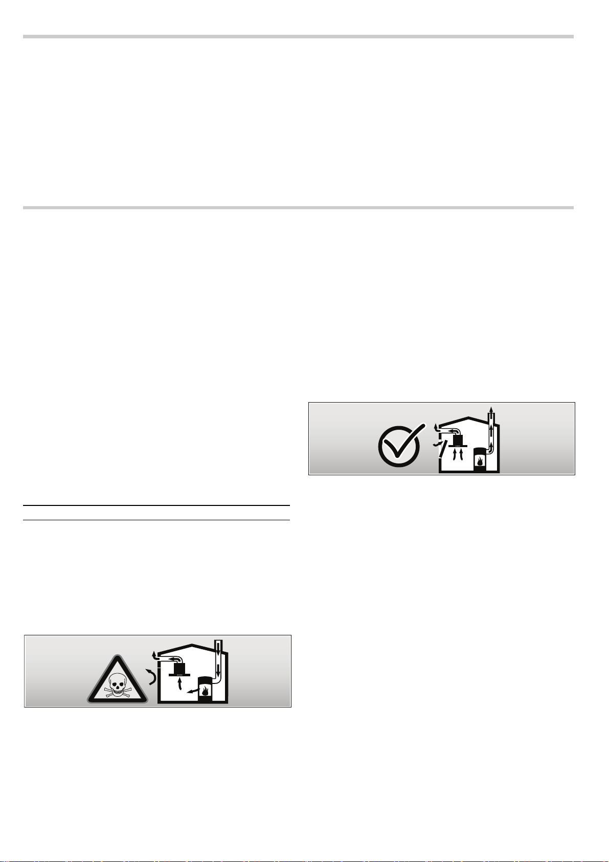
致命危险,有中毒的危险 !
原因在于燃气回吸。除非确保新鲜空气供应充足,否则在电器处
于排风模式时,切勿同时使用依靠室内空气工作的生热电器。
安装说明 ...................................................................................... 6
安全注意事项................................................................................ 6
管路尺寸.......................................................................................6
检查墙体.......................................................................................7
准备安装.......................................................................................7
安装 .............................................................................................. 7
连接烟道管 ...................................................................................9
依靠室内空气燃烧的生热设备 ( 例如使用燃气、燃油、木头或煤炭
的加热器、连续流加热器或热水器 ) 消耗所在安装室内的空气,并
通过排气系统 ( 例如烟囱 ) 将废气排放到室外。
在抽油烟机启动的情况下,厨房和相邻房间内的空气会被
抽走 —如果新鲜空气供应不足,会形成局部真空。烟道或
排气井的毒气被回吸到生活区。
■ 因此必须始终保证充足的进风。
■ 仅靠进气 / 排气壁箱将无法确保房间气压符合限值。
只有燃烧设备所在位置的局部真空压力不超过 4 Pa (0.04 mbar),
才能确保安全操作。只要燃烧所需的空气能够通过无法密封的开
口进入房间 ( 例如通过门、窗、进风 / 排风壁箱或其它技术手段 ),
就能达到这个要求。
在任何情况下,都要咨询负责卫生的烟囱清洁工。他能够评估房
屋的整个通风情况,并能建议您采取合适的通风措施。
如果抽油烟机只使用循环模式,则操作不受限制。
有着火危险 !
飞溅的火花会导致这类危险。除非使用封闭、不可移动的盖板,
否则请勿将电器安装在固体燃料 ( 例如木头或煤炭 ) 加热器上方。
小心!
若电器和设备高侧或墙壁之间的间隙过于狭窄,则存在因热积聚
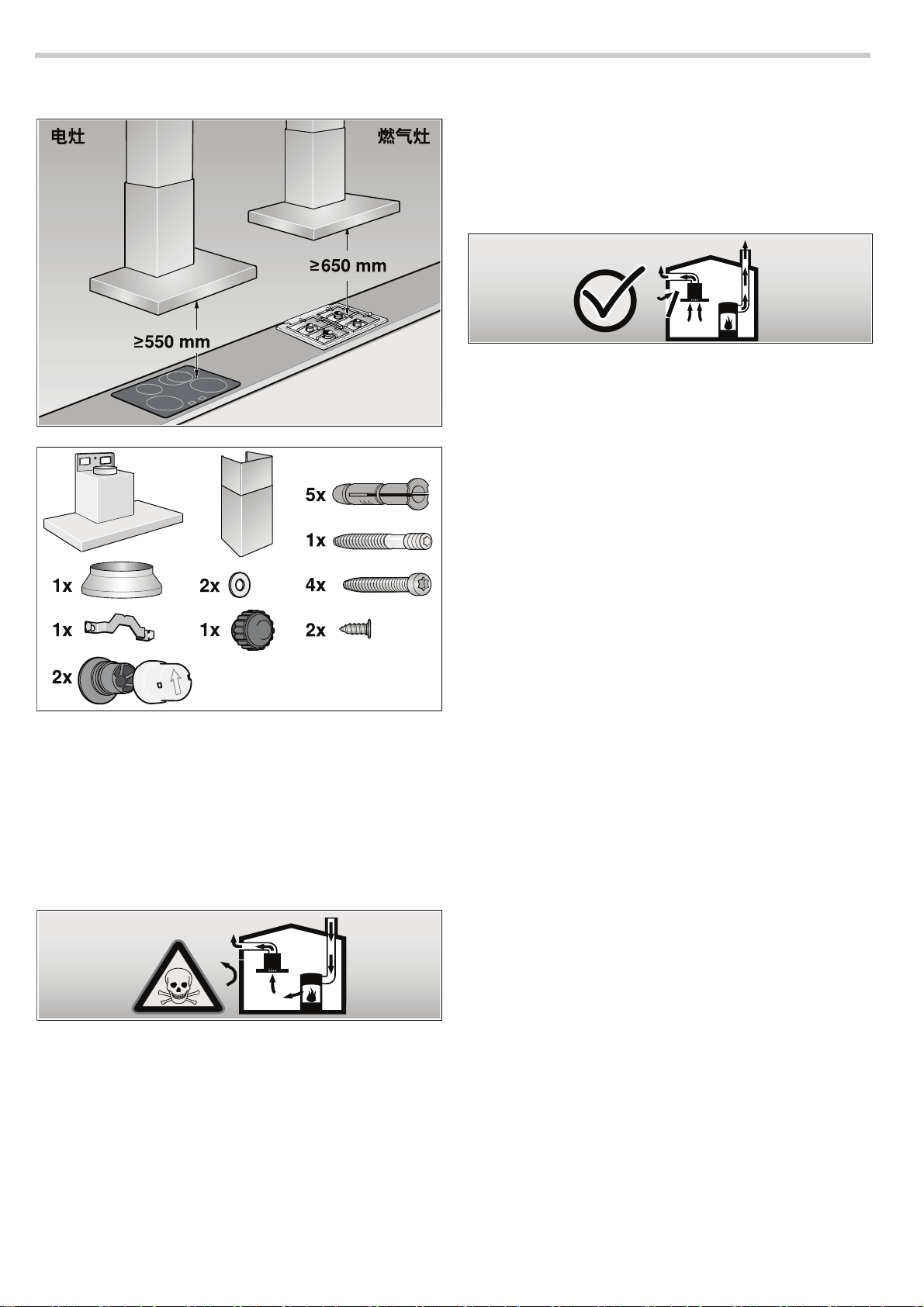
而导致损坏的风险。只能将电器的一侧紧靠设备高侧或墙壁安装。
电器和墙壁或高侧设备之间的间距不得小于 50 mm。
必须遵守规定的安全距离。同时必须遵守烹饪电器的技术规范。
如果燃气灶和电灶一起使用,则采用最长的规定距离。
抽油烟机的宽度必须至少达到灶具的宽度。
2
Page 3

安装时请遵守当前有效的建筑规范以及当地电力和燃气供应商的
规范。
有电击危险 !
受损的连接电缆会导致这类危险。安装时请勿缠绕或挤压连接
电缆。
有着火危险,有受伤危险 !
受损的连接电缆会导致这类危险。受损的连接电缆必须由具备相
应资格的技术人员 ( 电工 ) 进行更换。
■ 过热的脂肪和油会导致这类危险。加热脂肪或油时必须有人照
看。切勿用水灭火,必须用灭火毯、盖子或板灭火。
小心!
有因腐蚀而导致损坏的危险。烹饪时必须开启电器,避免出现冷
凝现象。冷凝可产生腐蚀损坏。
有受伤危险 !
属于危险组 1 的 LED 灯会导致危险。直视点亮的 LED 灯的时间请
勿超过 100 秒。
有受伤危险 !
安装期间尖锐的边缘会导致这类危险。安装电器时务必佩戴保护
手套。
有受伤危险 !
跌落的电器会导致这类危险。所有安全螺钉和安全罩盖必须装配
牢固。
使用电器
有灼伤危险 !
与烹饪电器一起使用时,发烫的电器会导致这类危险。不要让儿
童靠近,并确保正确使用电器。
有受伤危险,有损坏危险 !
物体掉落在电器上会导致这类危险。切勿将物体放在电器上。
有着火危险,有灼伤危险 !
如果燃气灶头上没有放置烹饪器具,会导致这类危险。在使用燃
气灶头时请务必在灶头上放置合适的烹饪器具。调控火焰,确保
火焰不盖过烹饪器具。
有灼伤危险,有损坏危险 !
多个燃气灶头同时工作时会导致这类危险。切勿以最大火同时
使用两个燃气灶头 15 分钟以上。由于热量过高,外壳将变得非
常热。
说明:功率在 5 kW 以上的大燃烧器 ( 炒锅 ) 相当于两个气体燃烧
器的功率。
有着火危险!
■ 金属网油脂过滤器中的油脂沉积物会导致这类危险。电器下方切
勿使用明火 ( 例如用烈酒燃烧方式烹饪 )。电器必须使用金属网
油脂过滤器。定期清理金属网油脂过滤器。
清洁和保养
有灼伤危险,有电击危险 !
电器会导致这类危险。请务必等到电器冷却后再进行清洁或维护。
切断保险丝或拔出电源插头。
小心!
■ 电子线路受潮会带来损坏风险。切勿使用湿布清洁操作按钮。
■ 清洁不当会导致表面损坏。只能沿着打磨方向清洁不锈钢表面。
请勿使用任何不锈钢清洁剂清洁操作按钮。
■ 烈性或磨蚀性清洁剂会导致表面损坏。切勿使用烈性和磨蚀性清
洁剂。
维护和修理
有着火危险,有受伤危险 !
修理不当会导致这类危险。切断保险丝或拔出电源插头。只能由
具备相应资格的技术人员 ( 电工 ) 进行修理。
有受伤危险 !
有故障或损坏的电器会导致这类危险。切断保险丝或拔出电源插
头,并拨打客户服务电话。
有着火危险,有受伤危险 !
受损的连接电缆会导致这类危险。受损的连接电缆必须由具备相
应资格的技术人员 ( 电工 ) 进行更换。
有灼伤危险,有电击危险 !
有故障的灯泡会导致这类危险。切断保险丝或拔出电源插头。请
立即更换有故障的灯泡 ( 先等灯泡冷却 ),防止其余灯泡过载。
操作模式
本电器可在排风模式或循环模式下使用。
排风模式
吸入的空气通过油脂过滤器进行清洁,然后通过
管路系统被输送至外部。
说明: 不得将废气排入正在使用的烟气或废气管道中,也不得排
入为加热电器所在的安装室进行通风的通风井中。
■ 在将废气排入停止使用的烟气或废气管道之前,请先征求负责此
事的加热工程师的同意。
■ 如果穿过外墙排放废气,应该使用伸缩式壁箱。
循环模式
吸入的空气通过几个油脂过滤器和一个活性碳过滤
器进行清洁,然后被送回厨房。
说明: 为消除循环模式下的异味,必须安装活性碳过滤器。如要
了解在循环模式下操作电器的不同选项,请参见手册或询问经销
商。所需的附件可从专卖店、客户服务处或在线商店获得。附件
编号可以在使用说明书末尾找到。
3
Page 4
操作
&
'
()
会ⵙ会优
'()&F
会ⵙ会优
以下说明适用于多款电器型号。在此所述的个别特点可能不
适用于您的电器。
说明: 开始烹饪时先开启抽油烟机,烹饪结束时等几分钟再
关闭
—
这是清除厨房油烟的最有效方法。
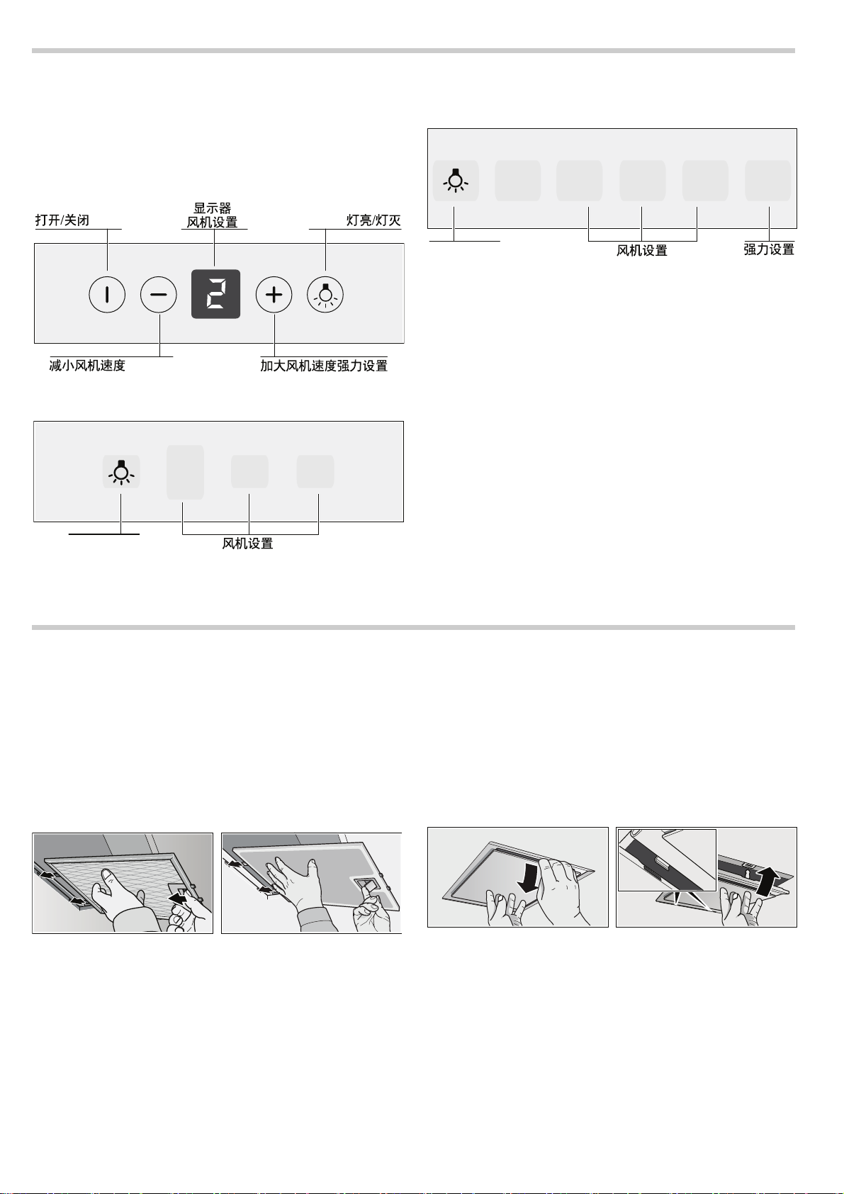
控制面板型式 1
控制面板型式 2
控制面板型式 3
开启风机:型式 1
按下开启 / 关闭按钮。
按下按钮
加强设置
对于特别强烈的异味和油烟,可以使用加强设置。
一直按住按钮
运行时间有限制。然后电器会自动设置较低的风机风量。始终可
以手动往回切换。
@:加大风机风量;按下按钮 A:减小风机风量。
@ ,直到显示屏上出现 ˜ / › 。
开启风机:型式 2 和 3
通过按下按钮 1、2 和 3 来增大或减小风机风量。
强度设置:型式 3
按下按钮
˜。
安装和拆除过滤器
: 有灼伤危险,有电击危险 !
电器会导致这类危险。请务必等到电器冷却后再进行清洁或维护。
切断保险丝或拔出电源插头。
拆除金属网油脂过滤器
1. 打开锁,将金属网油脂过滤器向下折。
此时,将另一只手放在金属网油脂过滤器下方。
2. 从托架上取出金属网油脂过滤器。
灯
灯可以单独开启和关闭,不受风机影响。
带边缘抽风管
1. 向下拉金属网油脂过滤器。
此时,将另一只手放在金属网油脂过滤器下方。
2. 从托架上取出金属网油脂过滤器。
说明
■ 油脂会积聚在金属网油脂过滤器的底部。
– 请勿倾斜金属网油脂过滤器,否则油脂将会滴出。
安装金属网油脂过滤器
1. 插入金属网油脂过滤器。
此时,将另一只手放在金属网油脂过滤器下方。
2. 折起金属网油脂过滤器并锁好。
4
Page 5
清洁和保养
: 有灼伤危险,有电击危险 !
电器会导致这类危险。请务必等到电器冷却后再进行清洁或维护。
切断保险丝或拔出电源插头。
小心!
■ 有因电子线路受潮而造成损坏的风险。切勿使用湿布清洁操作
按钮。
■ 清洁不当会导致表面损坏。只能沿着打磨方向清洁不锈钢表面。
请勿使用任何不锈钢清洁剂清洁操作按钮。
■ 烈性或磨蚀性清洁剂会导致表面损坏。切勿使用烈性和磨蚀性清
洁剂。
清洁电器表面
可以通过热线电话或在线商店购买适用于本电器的清洁剂和护理
产品 ( 参见使用说明书的封面 )。
说明: 电器表面和控制按钮很容易刮伤。请遵守随附的维修手册
上的保修条款以及下列清洁说明:
■ 只能使用柔软的湿布、洗涤液或温和的窗户清洁剂清洁电器表
面。使用湿布软化变干的污渍。请勿刮伤!
■ 不宜使用干布、磨蚀性海绵、擦洗剂、含有侵蚀性物质的清洁剂
( 如砂、苏打、酸、氯化物或任何其它类似物质 )。
■ 只能沿着不锈钢表面的打磨方向清洁不锈钢表面。
■ 请勿使用不锈钢清洁剂或湿布清洁控制按钮。
清洁金属网油脂过滤器
插入的金属网油脂过滤器可以吸收厨房油烟中的油脂颗粒。在正
常使用情况下 ( 每天使用 1 至 2 个小时 ),大约每三个月清洁一次
金属网油脂过滤器。
说明
■ 请勿使用任何侵蚀性、酸性或碱性清洁剂。
■ 在清洁金属网油脂过滤器时,还要用湿布清洁电器中的金属网油
脂过滤器托架。
■ 可以将金属网油脂过滤器放在洗碗机中清洗或用手清洗。
在洗碗机中清洗:
说明: 如果将金属网油脂过滤器放在洗碗机中清洗,可能会出现
轻微褪色。这不会影响金属网油脂过滤器的功能。
■ 请勿将积满油污的金属网油脂过滤器与烹饪器具一起清洁。
■ 将金属网油脂过滤器松散地放在洗碗机中。金属网油脂过滤器不
得拥挤放置。
用手清洗:
说明: 对于顽固污渍,可以使用特殊的油脂溶剂。该油脂溶剂可
以通过在线商店订购。
■ 将金属网油脂过滤器浸泡在热肥皂液中。
■ 使用刷子清洁过滤器,然后彻底漂洗。
■ 沥干金属网油脂过滤器上的水。
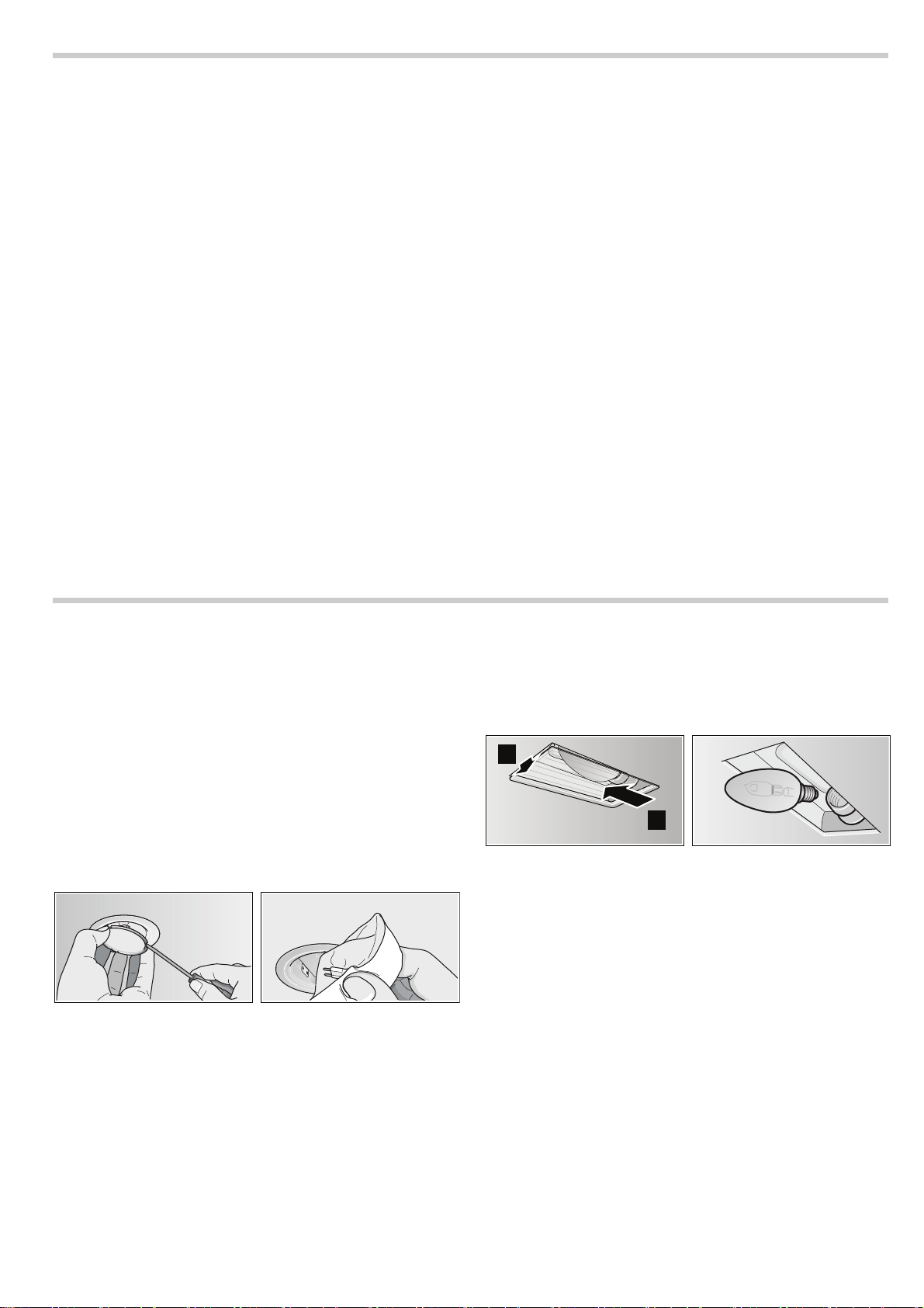
更换灯泡
: 有灼伤危险,有电击危险 !
有故障的灯泡会导致这类危险。切断保险丝或拔出电源插头。请
立即更换有故障的灯泡 ( 先等灯泡冷却 ),防止其余灯泡过载。
重要!只能使用相同类型和相同功率的灯泡 ( 参见电器内的灯座或
铭牌 )
—
为此需拆下金属网油脂过滤器。
更换卤素灯泡
说明: 插入卤素灯泡时,请勿触摸玻璃管。用干净的布裹住卤素
灯泡,将其插入灯座。
1. 使用合适的工具小心拆下灯泡护圈。
2. 拔出灯泡并更换为相同类型的灯泡。
3. 插入灯罩。
4. 插入电源插头,或重新接通保险丝。
更换白炽灯泡
1. 轻轻抬起灯罩,并将其推向电器的外部。
2. 拧下灯泡并更换为相同类型的灯泡。
3. 插入灯罩。
4. 插入电源插头,或重新接通保险丝。
LED 灯
有故障的 LED 灯只能由制造商、制造商客户服务人员或具备相应
资格的技术人员 ( 电工 ) 进行更换。
: 有受伤危险 !
属于危险组 1 的 LED 灯所导致的危险。直视点亮的 LED 灯的时间
请勿超过 100 秒。
5
Page 6
安装说明
■ 因此必须始终保证充足的进风。
■ 仅靠进气 / 排气壁箱将无法确保房间气压符合限值。
只有燃烧设备所在位置的局部真空压力不超过 4 Pa (0.04 mbar),
才能确保安全操作。只要燃烧所需的空气能够通过无法密封的开
口进入房间 ( 例如通过门、窗、进风 / 排风壁箱或其它技术手段 ),
就能达到这个要求。
在任何情况下,都要咨询负责卫生的烟囱清洁工。他能够评估房
屋的整个通风情况,并能建议您采取合适的通风措施。
如果抽油烟机只使用循环模式,则操作不受限制。
: 有着火危险 !
飞溅的火花会导致这类危险。除非使用封闭、不可移动的盖板,
否则请勿将电器安装在固体燃料 ( 例如木头或煤炭 ) 加热器上方。
安装时请遵守当前有效的建筑规范以及当地电力和燃气供应商的
规范。
: 有电击危险 !
受损的连接电缆会导致这类危险。安装时请勿缠绕或挤压连接
电缆。
■ 本电器安装在墙壁上。
■ 使用额外的专用附件 ( 例如用于循环模式 ) 时,请遵循附随的安
装说明。
■ 电器表面属于敏感型表面。安装时避免损坏电器表面。
安全注意事项
: 致命危险,有中毒的危险 !
原因在于燃气回吸。除非确保新鲜空气供应充足,否则在电器处
于排风模式时,切勿同时使用依靠室内空气工作的生热电器。
依靠室内空气燃烧的生热设备 ( 例如使用燃气、燃油、木头或
煤炭的加热器、连续流加热器或热水器 ) 消耗所在安装室内的
空气,并通过排气系统 ( 例如烟囱 ) 将废气排放到室外。
在抽油烟机启动的情况下,厨房和相邻房间内的空气会被
抽走
—
如果新鲜空气供应不足,会形成局部真空。烟道或
排气井的毒气被回吸到生活区。
: 有受伤危险 !
安装期间尖锐的边缘会导致这类危险。安装电器时务必佩戴保护
手套。
: 有受伤危险 !
跌落的电器会导致这类危险。所有安全螺钉和安全罩盖必须装配
牢固。
管路尺寸
说明: 对于针对管路部分的投诉,设备制造商不承担任何保修
责任。
■ 设备使用短而直的烟管可发挥最佳性能,且管径应尽可能大。
■ 使用带有许多弯折或粗细不匀的长而粗糙的烟管的结果是:无法
达到最佳的抽风性能,且风机噪音增加。
■ 用于铺设烟管的管道或软管必须采用不可燃的材料制成。
圆管
建议圆管内径为 150 mm,最小不能小于 120 mm。
扁平管
内部横截面积必须对应于圆管的直径。
Ø 150 mm 约为 177 cm
Ø 120 mm 约为 113 cm
■ 扁平管不应有明显偏斜。
■ 对于有偏斜的管径,使用密封条加以密封。
2
2
6
Page 7

检查墙体
Y
"
■ 墙壁必须水平、垂直且足以承受负荷。
■ 钻孔深度必须和螺钉的长度一致。墙塞必须具有固定夹。
■ 随设备配套提供的螺钉和墙塞适合于实心砖砌体。对于其它结构
( 例如石膏板、多孔混凝土、波罗顿 (Poroton) 砖 ),必须使用合
适的紧固件。
■ 抽油烟机的最大重量为 40 kg。
准备安装
1. 从天花板到抽油烟机的下部边缘,在墙壁上画一条垂直中心线。
2. 标记螺钉的位置和安装区域的轮廓。
3. 钻出 5 个 Ø 8 mm、80 mm 深的固定孔,用于安装抽油烟机,
并按入墙塞,使其与墙壁齐平。
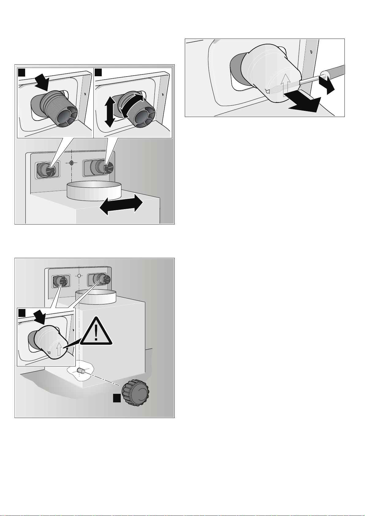
2. 用手拧紧抽油烟机支架,最大 3 Nm。 ©
3. 拧入螺纹销,使其突出墙外的部分为 5–9 mm。 ª
安装
1. 拧上烟道管固定支架。 ¨
$
7
Page 8
安装和调平电器
%
&
'
(
1. 先从电器的背面撕下保护膜,安装后,完全撕掉保护膜。
2. 在安装电器时,请确保电器与固定支架紧密结合。 «
3. 转动支架,水平调整电器。如有需要,可以将电器向右或向左
移动。
¬
拆下安全锁紧帽
如果必须拆下安全锁紧帽,请使用一字型螺丝刀。
连接管路
说明: 如果使用铝材管路,请预先确保连接区域平滑。
Ø 150 mm 烟管 ( 推荐尺寸 )
将烟管直接连接到风管连接件并加以密封。
Ø 120 mm 烟管
1. 将缩径连接件直接安装到风管连接件。
2. 将烟管直接安装到缩径连接件。
3. 妥善密封两个连接件。
固定电器
1. 将安全锁紧帽按到支架上 ( 箭头朝上 ),直到其固定到位。 ®
2. 拧紧滚花螺母和垫圈。 ¯
电气连接
: 有电击危险 !
受损的连接电缆会导致这类危险。安装时请勿缠绕或挤压连接
电缆。
所要求的连接数据可以在电器内部的铭牌上找到;为此,拆下金
属网油脂过滤器。
连接电缆的长度:大约 1.30 m
本电器遵守 EC 射频干扰抑制规范。
只能将电器连接至安装正确的接地插座。
最好将接地插座安装在烟道管内部。
■ 应该通过接地插座自带的电路连接接地插座。
■ 如果在安装电器后难以触及接地插座,则必须安装一个永久型隔
离开关。
如果需要永久连接,必须安装触点间隙最小为 3 mm 的全电极隔离
开关 ( 断路器、保险丝和接触器 )。只能由电工完成永久连接。
8
Page 9

连接烟道管
: 有受伤危险 !
安装期间尖锐的边缘会导致这类危险。安装时务必佩戴保护手套。
"
#
$
1. 分隔烟道管。
如要分隔烟道管,先撕下胶带。
2. 撕去两条烟道管上的保护膜。
3. 将一条烟道管推入另一条烟道管中。
说明
■ 用纸张包住外层烟道管边缘,避免刮伤。
– 里面那根烟道管的插槽必须从上至下。
4. 将烟道管放在电器上。
5. 把内层烟道管向上推,将其固定到左右两侧的固定支架上。 ¨
6. 向下按烟道管,直到其固定到位。 ©
7. 用两个螺钉将烟道管拧紧到固定支架的两侧。 ª
9
Page 10
Ú Table of contents
Safety instructions...................................................................10
Operating modes......................................................................11
Exhaust air mode .......................................................................11
Circulating-air mode ...................................................................11
Operation ..................................................................................12
Installing and removing filter..................................................12
Cleaning and care ....................................................................13
Replacing bulbs........................................................................13
: Safety instructions
General information
Follow these instructions, in particular the safety instructions.
The appliance can only be used safely if it is correctly installed
according to the safety instructions. Retain the instructions
for subsequent use or for the next owner.
This appliance is designed to be used in the home only.
The manufacturer is not liable for damage which is caused
by improper use or incorrect operation.
Danger of suffocation!
from packaging material. Never allow children to play
with packaging material.
After unpacking the appliance, check it for visible damage.
Do not connect the appliance if it has been damaged in transit.
These instructions apply to several appliance models.
It is possible that individual features are described which do not
apply to your appliance.
Adults and children must never use the appliance unsupervised
if they are not physically or mentally capable of doing so or if they
lack the knowledge and experience to operate the appliance
correctly and safely.
Never allow children to play with the appliance!
Please contact our customer service regarding any queries
or faults (see list of customer service centres).
When calling, please quote the following numbers:
E-Nr. FD
The numbers can be found on the rating plate inside
the appliance (to do this, remove the metal-mesh grease filter).
Enter the numbers in the above box so that you can easily find
them when required.
Installation
Mortal danger, risk of intoxication!
Due to combustion gases sucked back in. Never operate the
appliance in the exhaust air mode at the same time as a room airdependent heat-producing appliance unless an adequate supply
of fresh air is ensured.
Installation instructions...........................................................14
Safety notes ...............................................................................14
Pipe dimensions......................................................................... 14
Checking the wall ....................................................................... 15
Preparing the installation............................................................ 15
Installation ..................................................................................15
Attaching flue duct......................................................................17
Room air-dependent heat-producing appliances (e.g. gas, oil,
wood or coal-operated heaters, continuous flow heaters or water
heaters) obtain combustion air from the room in which they are
installed and discharge the exhaust gases into the open through
an exhaust gas system (e.g. a chimney).
In combination with an activated vapour extractor hood, room air
is extracted from the kitchen and neighbouring rooms - a partial
vacuum is produced if not enough fresh air is supplied. Toxic
gases from the chimney or the extraction shaft are sucked backed
into the living space.
■ Adequate incoming air must therefore always be ensured.
■ An incoming/exhaust air wall box alone will not ensure
compliance with the limit.
Safe operation is possible only whenever the partial vacuum in
the place where the firing equipment is installed does not exceed
4 Pa (0.04 mbar). This can be achieved whenever the air needed
for combustion is able to enter through openings that cannot be
sealed, for example in doors, windows, incoming/exhaust air wall
boxes or by other technical means.
In any case, consult your responsible chimney sweep. He is able
to assess the house's entire ventilation setup and will suggest the
suitable ventilation measures to you.
Unrestricted operation is possible if the vapour extractor hood is
operated exclusively in the recirculation mode.
Risk of fire!
from flying sparks. Do not install appliance above a solid fuel
heater (e.g. wood or coal) unless a closed, non-removable cover
is available.
Caution!
Risk of damage from heat accumulation due to too narrow gap
between appliance and high-sided unit or wall. Only one side
of the appliance may be installed directly next to a high-sided unit
or a wall. Distance between the appliance and wall or high-sided
unit must be at least 50 mm.
The specified safety distances must be observed. Also observe
the specifications for your cooking appliance. If gas and electric
hobs are operated together, the largest specified distance
applies.
The width of the extractor hood must correspond at least
with the width of the hob.
10
Page 11

For the installation observe the currently valid building regulations
and the regulations of the local electricity and gas suppliers.
Risk of electric shock!
from damaged connection cable. Do not kink or pinch connection
cable during installation.
Risk of fire, risk of injury!
from damaged connection cable. A damaged connection cable
must be replaced by a qualified technician (electrician).
Risk of injury!
From sharp edges during installation. Always wear protective
gloves while installing the appliance.
Risk of injury!
from a falling appliance. All safety screws and safety caps must
be firmly fitted.
Using the appliance
Risk of burns!
from hot appliance when used with cooking appliances. Keep
children away and ensure appliance is used properly.
Risk of injury, risk of damage!
from objects falling on the appliance. Never place objects
on the appliance.
Risk of fire, risk of burns!
if gas hotplates not covered with cooking utensils. Always use gas
hotplates with appropriate cooking utensils. Regulate flame
to ensure that it does not lick over the cooking utensil.
Risk of burns, risk of damage!
if several gas hotplates are operated simultaneously. Never
operate two gas hotplates simultaneously on the highest flame
for longer than 15 minutes. The housing will become very hot due
to the intense heat.
Note: One large burner of more than 5 kW (Wok) is equivalent
to the power of two gas burners.
Risk of fire!
■ from grease deposits in the metal-mesh grease filter. Never
work under the appliance with a naked flame (e.g. flambéing).
Always operate appliance with metal-mesh grease filter.
Regularly clean the metal-mesh grease filter.
■ from overheated fats and oils. Heat fats and oils under constant
supervision only. Never extinguish fire with water, always use
a fire blanket, lid or plate.
Caution!
Risk of damage due to corrosion. Always switch on the appliance
while cooking to avoid condensation. Condensate can produce
corrosion damage.
Risk of injury!
due to LED lights of risk group 1. Do not look directly into the
switched on LED lights for longer than 100 seconds.
Cleaning and care
Risk of burns, risk of electric shock!
from appliance. Always leave appliance to cool down before
cleaning or servicing. Switch off fuse or pull out mains plug.
Caution!
■ Risk of damage due to ingress of humidity into the electronic
circuitry. Never clean operator controls with a wet cloth.
■ Surface damage due to incorrect cleaning. Clean stainless steel
surfaces in the grind direction only. Do not use any stainless
steel cleaners for operator controls.
■ Surface damage due to strong or abrasive cleaning agents.
Never use strong and abrasive cleaning agents.
Maintenance and repair
Risk of fire, risk of injury!
from improper repairs. Switch off fuse or pull out mains plug.
Repairs may be performed by a qualified technician (electrician)
only.
Risk of injury!
from defective or damaged appliance. Switch off fuse or pull out
mains plug and call customer service.
Risk of fire, risk of injury!
from damaged connection cable. A damaged connection cable
must be replaced by a qualified technician (electrician).
Risk of burns, risk of electric shock!
from defective bulbs. Switch off fuse or pull out mains plug.
Always replace defective bulbs immediately (leave bulbs
to cool down first) to prevent the remaining bulbs from
overloading.
Operating modes
This appliance can be used in exhaust-air mode or circulating-air
mode.
Exhaust air mode
The air which is drawn in is cleaned by the
grease filters and conveyed to the exterior by a
pipe system.
Note: The exhaust air must not be conveyed into a functioning
smoke or exhaust gas flue or into a shaft which is used to
ventilate installation rooms which contain heating appliances.
■ Before conveying the exhaust air into a non-functioning smoke
or exhaust gas flue, obtain the consent of the heating engineer
responsible.
■ If the exhaust air is conveyed through the outer wall, a
telescopic wall box should be used.
Circulating-air mode
The air which is drawn in is cleaned by the grease
filters and an activated carbon filter and conveyed
back into the kitchen.
Note: To bind odours in circulating-air mode, you must install
an activated carbon filter. The different options of operating
the appliance in circulating-air mode can be found in the brochure
or ask your dealer. The required accessories are available from
specialist outlets, from customer service or from the Online Shop.
The accessory numbers can be found at the end
of the instructions for use.
11
Page 12

Operation
-JHIU0O0GG
0O0GG
%JTQMBZ
GBOTFUUJOHT
3FEVDFGBOTQFFE *ODSFBTFGBOTQFFE
*OUFOTJWFTFUUJOH
&
'
()
-JHIU0O0GG
'BOTFUUJOHT
'()&F
-JHIU0O0GG
'BOTFUUJOHT
*OUFOTJWF
TFUUJOH
These instructions apply to several appliance models.
It is possible that individual features are described which
do not apply to your appliance.
Note: Switch on the extractor hood when you start cooking
and switch it off again several minutes after you have finished
cooking. This is the most effective way of removing the kitchen
fumes.
Control panel variant 1
Control panel variant 2
Control panel variant 3
Switching on fan: variant 1
Press On/Off button.
Increase fan setting by pressing button
it by pressing button
Intensive setting
You can use the Intensive setting for particularly strong odour
and fume generation.
Keep pressing button
Run time is limited. Then the appliance sets automatically a lower
fan setting. You can always switch back manually.
A.
@ until ˜ / › is indicated on the display.
@ or reduce
Switching on fan: variants 2 and 3
Increase or reduce the fan settings by pressing
buttons 1, 2 and 3.
Intensive setting: variant 3
Press button
˜.
Installing and removing filter
: Risk of burns, risk of electric shock!
from appliance. Always leave appliance to cool down before
cleaning or servicing. Switch off fuse or pull out mains plug.
Removing metal-mesh grease filter
1. Open lock and fold down the metal-mesh grease filter.
In doing so, place other hand under the metal-mesh grease
filter.
2. Take metal-mesh grease filter out of the holder.
Light
The light can be switched on and off independently of the fan.
With edge extraction
1. Pull metal-mesh grease filter downwards.
In doing so, place other hand under the metal-mesh grease
filter.
2. Take metal-mesh grease filter out of the holder.
Notes
■ Grease can accumulate in the bottom of the metal-mesh
grease filter.
– Do not hold metal-mesh grease filter at an angle, otherwise
grease will drip out.
12
Installing metal-mesh grease filter
1. Insert metal-mesh grease filter.
In doing so, place other hand under the metal-mesh grease
filter.
2. Fold up metal-mesh grease filter and lock.
Page 13

Cleaning and care
: Risk of burns, risk of electric shock!
from appliance. Always leave appliance to cool down before
cleaning or servicing. Switch off fuse or pull out mains plug.
Caution!
■ Risk of damage due to ingress of humidity into the electronic
circuitry. Never clean operator controls with a wet cloth.
■ Surface damage due to incorrect cleaning. Clean stainless steel
surfaces in the grind direction only. Do not use any stainless
steel cleaners for operator controls.
■ Surface damage due to strong or abrasive cleaning agents.
Never use strong and abrasive cleaning agents.
Cleaning appliance surface
Suitable cleaning agents and care products for your appliance
can be purchased via the Hotline or from the Online Shop (see
front of the instructions for use).
Note: The appliance surface and controls are scratch-sensitive.
Observe the warranty regulations in the enclosed service booklet
and the following cleaning instructions:
■ Clean the surfaces with a soft, damp cloth, washing-up liquid
or a mild window cleaner. Soften dried dirt with a damp cloth.
Do not scratch!
■ Dry cloths, abrasive sponges, scouring agents, cleaning agents
containing sand, soda, acid, chlorine or any other aggressive
substances are not suitable.
■ Clean the stainless steel surfaces in the direction of the ground
surface only.
■ Do not use stainless steel cleaner or wet cloths for the controls.
Cleaning metal-mesh grease filters
The inserted metal-mesh grease filters absorb the grease
particles from the kitchen fumes. Clean the metal-mesh grease
filters under normal use (1 to 2 hours daily) approx. every three
months.
Notes
■ Do not use any aggressive, acidic or alkaline cleaning agents.
■ When cleaning the metal-mesh grease filters, also clean
the holder for the metal-mesh grease filters in the appliance
using a damp cloth.
■ The metal-mesh grease filters can be cleaned
in the dishwasher or by hand.
In the dishwasher:
Note. If the metal-mesh grease filters are cleaned
in the dishwasher, slight discolouration may occur. This has no
effect on the function of the metal-mesh grease filters.
■ Do not clean heavily soiled metal-mesh grease filters together
with utensils.
■ Place the metal-mesh grease filters loosely in the dishwasher.
The metal-mesh greases filter must not be wedged in.
By hand:
Note. You can use a special grease solvent for stubborn dirt.
It can be ordered via the Online Shop.
■ Soak the metal-mesh grease filters in a hot soapy solution.
■ Clean the filters with a brush and then rinse them thoroughly.
■ Leave the metal-mesh grease filters to drain.
Replacing bulbs
: Risk of burns, risk of electric shock!
from defective bulbs. Switch off fuse or pull out mains plug.
Always replace defective bulbs immediately (leave bulbs
to cool down first) to prevent the remaining bulbs from
overloading.
Important! Use only bulb of the same type and same power (see
bulb holder or rating plate inside the appliance) – to do this
remove metal-mesh grease filter.
Replacing halogen bulbs
Note. When inserting halogen bulbs, do not touch the glass tube.
Use a clean cloth to insert the halogen bulbs.
1. Carefully remove bulb ring using a suitable tool.
2. Pull out bulb and replace with bulb of the same type.
3. Insert bulb cover.
4. Insert mains plug or switch on fuse again.
Replacing filament bulbs
1. Lift bulb cover slightly and push towards the outside of the
appliance.
Unscrew bulb and replace with bulb of the same type.
2.
3. Insert bulb cover.
4. Insert mains plug or switch on fuse again.
LED lights
Defective LED lights may be replaced by the manufacturer, his
customer service or a qualified technician (electrician) only.
: Risk of injury!
due to LED lights of risk group 1. Do not look directly into the
switched on LED lights for longer than 100 seconds.
13
Page 14

Installation instructions
■ Adequate incoming air must therefore always be ensured.
■ An incoming/exhaust air wall box alone will not ensure
compliance with the limit.
Safe operation is possible only whenever the partial vacuum in
the place where the firing equipment is installed does not exceed
4 Pa (0.04 mbar). This can be achieved whenever the air needed
for combustion is able to enter through openings that cannot be
sealed, for example in doors, windows, incoming/exhaust air wall
boxes or by other technical means.
In any case, consult your responsible chimney sweep. He is able
to assess the house's entire ventilation setup and will suggest the
suitable ventilation measures to you.
Unrestricted operation is possible if the vapour extractor hood is
operated exclusively in the recirculation mode.
: Risk of fire!
from flying sparks. Do not install appliance above a solid fuel
heater (e.g. wood or coal) unless a closed, non-removable cover
is available.
For the installation observe the currently valid building regulations
and the regulations of the local electricity and gas suppliers.
: Risk of electric shock!
from damaged connection cable. Do not kink or pinch connection
cable during installation.
■ This appliance is installed on the wall.
■ Follow the enclosed installation instructions for additional
special accessories (e.g. for circulating-air mode).
■ The surfaces of the appliance are sensitive. Avoid damaging
them during installation.
Safety notes
: Mortal danger, risk of intoxication!
Due to combustion gases sucked back in. Never operate the
appliance in the exhaust air mode at the same time as a room
air-dependent heat-producing appliance unless an adequate
supply of fresh air is ensured.
Room air-dependent heat-producing appliances (e.g. gas, oil,
wood or coal-operated heaters, continuous flow heaters or
water heaters) obtain combustion air from the room in which
they are installed and discharge the exhaust gases into the
open through an exhaust gas system (e.g. a chimney).
In combination with an activated vapour extractor hood, room
air is extracted from the kitchen and neighbouring rooms - a
partial vacuum is produced if not enough fresh air is supplied.
Toxic gases from the chimney or the extraction shaft are
sucked backed into the living space.
: Risk of injury!
From sharp edges during installation. Always wear protective
gloves while installing the appliance.
: Risk of injury!
from a falling appliance. All safety screws and safety caps must
be firmly fitted.
Pipe dimensions
Note: The device manufacturer does not assume any warranty
for complaints attributable to the pipe section.
■ The device achieves its optimum performance by means of a
short, straight exhaust air pipe and as large a pipe diameter as
possible.
■ As a result of long rough exhaust air pipes, many pipe bends or
diameters, the optimum extraction performance is not achieved
and fan noise is increased.
■ The pipes or hoses for laying the exhaust air line must consist
of non-combustible material.
Round pipes
An inner diameter of 150 mm, but at least 120 mm, is
recommended.
Flat ducts
The inner cross-section must correspond to the diameter of the
round pipes.
Ø 150 mm approx. 177 cm
Ø 120 mm approx. 113 cm
■ Flat ducts should have no sharp deflections.
■ Use sealing strip for deviating pipe diameters.
2
2
14
Page 15

Checking the wall
NN
NN
NN
NN
NN
Y
"
NJONN
NBYNN
$
■ The wall must be level, vertical and adequately load-bearing.
■ The depth of the boreholes must be the same length
as the screws. The wall plugs must have a secure grip.
■ The enclosed screws and wall plugs are suitable for solid
brickwork. Suitable fasteners must be used for other structures
(e.g. plasterboard, porous concrete, poroton bricks).
■ The max. weight of the extractor hood is 40 kg.
Preparing the installation
1. Mark a vertical centre line on the wall from the ceiling
to the lower edge of the extractor hood.
2. Mark positions for the screws and the contour of the attachment
area.
3. Drill five 8 mm Ø holes to a depth of 80 mm for the attachments
andpress inthewall plugs flush with the wall.
2. Screw on brackets for the extractor hood hand-tight,
max. 3Nm.
©
#
Installation
1. Screw on the fixing bracket for the flue duct. ¨
3. Screw in threaded pin, leaving it protruding out of the wall
by 5–9 mm.
ª
15
Page 16

Attaching and aligning the appliance
%
&
'
(
1. Initially remove the protective foil from the back of the appliance
and, following installation, remove foil completely.
2. When attaching the appliance, ensure that it engages firmly
with the brackets.
3. Align the appliance horizontally by turning the brackets.
If required, the appliance can be moved to the right or left.
«
¬
Removing safety caps
If the safety caps have to be removed, use a flat screwdriver.
Connecting the pipes
Note: If using an aluminium pipe, smooth the connection area
beforehand.
Exhaust-air pipe Ø 150 mm (recommended size)
Attach exhaust-air pipe directly to the air-pipe connector and seal.
Exhaust-air pipe Ø 120 mm
1. Attach reducing connector directly to the air-pipe connector.
2. Attach exhaust air pipe to the reducing connector.
3. Seal both joints appropriately.
Securing the appliance
1. Press the safety caps with the arrow upwards onto the brackets
until they engage.
2. Screw on knurled nut and washer firmly. ¯
®
Electrical connection
: Risk of electric shock!
from damaged connection cable. Do not kink or pinch
connection cable during installation.
The required connection data can be found on the rating plate
inside the appliance; to do this, remove the metal-mesh grease
filter.
Length of the connection cable: approx. 1.30 m
This appliance complies with the EC interference suppression
regulations.
This appliance may be connected to a correctly installed earthed
socket only.
Attach the earthed socket preferably inside the flue duct.
■ The earthed socket should be connected via its own circuit.
■ If the earthed socket is no longer accessible following
installation of the appliance, a disconnector must be fitted
as for a permanent connection.
If a permanent connection is required, the installation must
feature an all-pole disconnector (circuit breakers, fuses
and contactors) with a min. 3 mm contact opening.
The permanent connection may be installed by an electrician
only.
16
Page 17
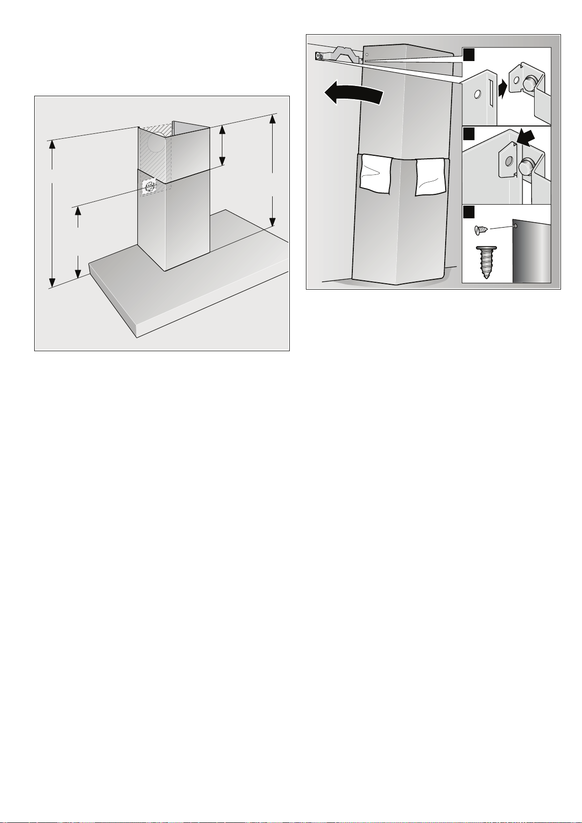
Attaching flue duct
NJO
NN
NJO
NN
NJO
NN
NBYNN
: Risk of injury!
From sharp edges during installation. Always wear protective
gloves while installing the appliance.
"
#
$
1. Separate the flue ducts.
To do this, remove the adhesive tape.
2. Remove the protective foil from both flue ducts.
3. Push one flue duct into the other.
Notes
■ To prevent scratches, place paper for protection over
the edges of the outer flue duct.
– Slots of the inner flue duct downwards.
4. Place flue ducts on the appliance.
5. Push inner flue duct upwards and attach to the fixing brackets
on the left and right.
6. Press flue duct downwards until it engages. ©
7. Screw flue duct to the sides of the fixing bracket using two
screws.
ª
¨
17
Page 18

%);
%);
%);
%);
%4;
%4;
%4;
%4;
18
Page 19

19
Page 20

Robert Bosch Hausgeräte GmbH
Carl-Wery-Straße 34
81739 München
Germany
www.bosch-home.com
*9000548227*
9000548227
 Loading...