

Page 1
Control Air M and M+
For Commercial Water to Water DDC Applications
Installation & Operation Manual
BTC 469503103 A (2019/02) US
Page 2

|
2
Control Air M/M+ Water to Water Applications Installation & Operation Manual
02.2019 | BTC 469503103 AData subject to change
Page 3

Installation & Operation Manual Control Air M/M+ Water to Water Applications | 3
Table of Contents
1 Key to Symbols and Safety Instructions 4
1.1 Key to Symbols 4
1.2 Safety Warnings 4
2 Introduction 5
2.1 The Control Air M/M+ Interfaces 5
2.2 The Control Air M/M+ Module 5
2.3 Virtual Control Air M/M+ (Equipment Touch (OEM) APP) 5
3 Specifi cations 6
4 Physical Dimensions 7
5 Wiring 8
5.1 Recommended Wiring Scheme 8
5.2 Rnet Wiring Specifi cations 8
6 Connection 8
6.1 Communicate Using a Tablet Through Virtual Control Air M and M+ 8
6.2 To Wire and Mount the Control Air M/M+ 8
6.3 Additional Information on Connecting Control Air
M/M+ to a Controller 9
9 The Control Air M and M+ Screens 14
9.1 Units Status Screen/Home Page 14
9.2 Settings Screen 14
9.2.1 Unit Settings Screen 14
9.2.2 Device Settings Screen 16
9.2.2.1 Controller Screen 16
9.2.2.1.1 Set Time and Date 16
9.2.2.1.2 Communication 16
9.2.2.1.3 Router 17
9.2.2.1.4 IP 17
9.2.2.1.5 Time Master 17
9.2.2.2 Touchscreen Screen 18
9.2.3 Alarms Settings Screen 18
9.2.4 Pumps 19
9.2.5 Temperature 19
9.2.6 Setpoints 19
9.2.7 Schedule Screen 20
9.2.8 Lead/Lag Screen 22
9.3 Service Screen 22
9.3.1 Heat/Cool Screen 23
9.3.2 UPM Status Screen 23
9.3.3 Help Screen 24
7 How to Navigate Screens in Control Air M/M+ 11
7.1 Login 11
7.2 Alarms 11
7.3 Trends 11
8 To Update the Control Air M/M+’s Firmware 12
8.1 Prerequisite 12
8.2 To Update the Firmware 12
8.3 Resetting the Control Air M/M+ 12
8.4 Compliance 13
BTC 469503103 A | 02.2019
Data subject to change
Page 4
|
4
Control Air M/M+ Water to Water Applications Installation & Operation Manual
1 Key to Symbols and Safety Instructions
1.1 Key to Symbols
Warnings
Warnings in this document are identifi ed by a warning
triangle printed against a grey background.
Keywords at the start of a warning indicate the type and
seriousness of the ensuing risk if measures to prevent the
risk are not taken.
The following keywords are defi ned and can be used in this document:
DANGER indicates a hazardous situation which, if not avoided,
will result in death or serious injury.
WARNING indicates a hazardous situation which, if not
avoided, could result in death or serious injury.
CAUTION indicates a hazardous situation which, if not
avoided, could result in minor to moderate injury.
NOTICE is used to address practices not related to personal
injury.
Important information
This symbol indicates important information where
there is no risk to people or property.
1.2 Safety Warnings
WARNING: ELECTRIC SHOCK HAZARD
Installation and servicing of this equipment can be
hazardous due to the electrical components. Only
trained and qualified personnel should install, repair,
or service the equipment.
WARNING: ELECTRIC SHOCK HAZARD
Before performing service or maintenance
operations on the system, turn off main power to the
unit. Electrical shock could cause personal injury or
death.
WARNING: FIRE, INJURY HAZARD
When working on equipment, always observe
precautions described in the literature, tags,
and labels attached to the unit. Follow all safety
codes. Wear safety glasses and work gloves. Use
a quenching cloth for brazing, and place a fire
extinguisher close to the work area.
WARNING: ELECTRIC SHOCK HAZARD
To Reduce the risk of Fire or Electric Shock, Do
not interconnect the outputs of different class 2
circuits.
WARNING:
This product can expose you to chemicals including
Lead and Lead components, which are known to
the State of California to cause cancer and birth
defects or other reproductive harm. For more
information go to
www.P65Warnings.ca.gov.
02.2019 | BTC 469503103 AData subject to change
Page 5
Installation & Operation Manual Control Air M/M+ Water to Water Applications | 5
2 Introduction
2.1 The Control Air M/M+ Interfaces
The Control Air M and M+ (M=Manager) is a Human-Machine Interface
(HMI) that interfaces with the BOSCH DDC Control Air 5600, enabling the
user to view and change property values, and/or control parameters, to
match a corresponding application whether it is a Water to Air or Water to
Water Heat Pump. It also provides a means of accessing and modifying the
controller’s schedule and real time clock in applications where a system
server or Building Automation System (BAS) is not available. The Control
Air M is designed for applications where there is one (1) WSHP. The
Control Air M+ is designed for applications where there is up to fi fty (50)
WSHP's (existing networks only).
The software is normally confi gured at the factory to match the unit
confi guration, however, there are cases where additional on-site changes
need to be made and this screen will allow the qualifi ed technical or
commissioning agent to incorporate such changes (without having to
download a diff erent software application) via the commissioning tool.
The interface is off ered in two forms: as a wall mount or unit mounted
Control Air M/M+module or in the form of an APP called the Equipment
Touch (OEM), which can be found in the Google Play Store (Android Only).
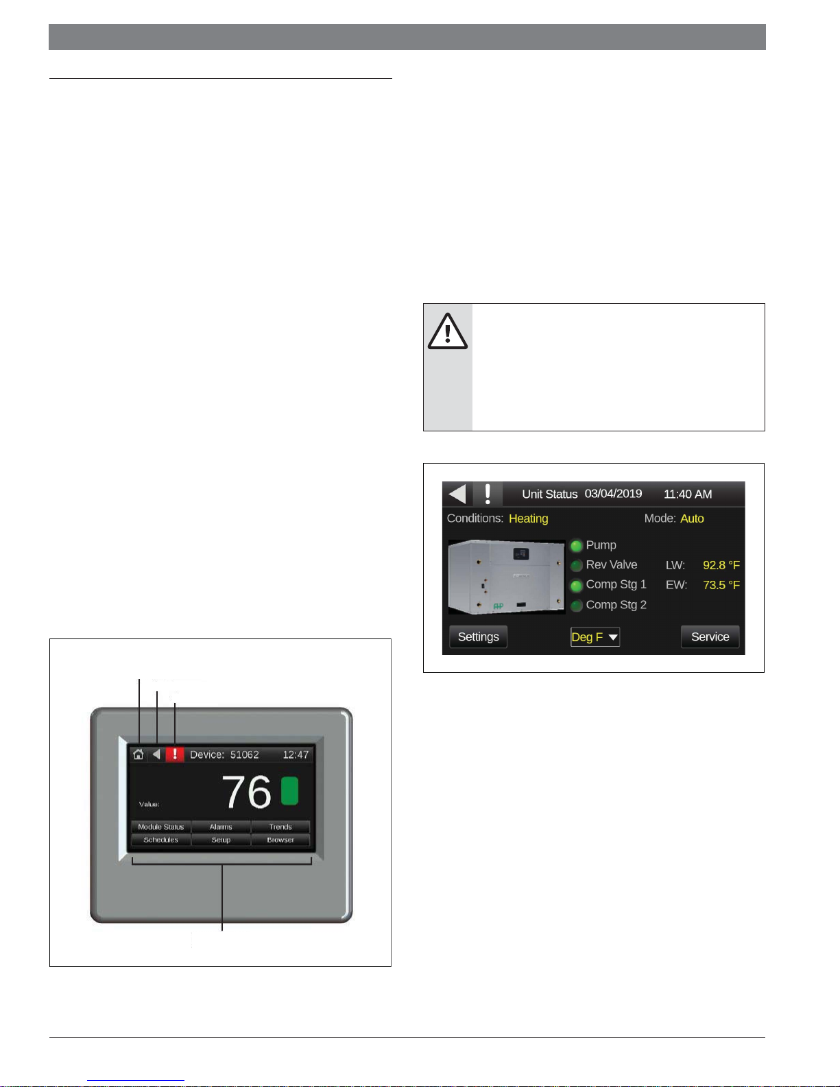
2.2 The Control Air M/M+ Module
The Control Air M/M+ module (Figure 1) is a touchscreen device with a
4.3" color LCD display that you connect to a Control Air 5600 to view or
change its property values, schedule units, view trends and alarms, and
more. The unit connects to the controller via the onboard serial port. The
module can be purchased by the following part numbers:
2.3 Virtual Control Air M/M+ (Equipment Touch (OEM) APP)
Virtual Control Air M/M+ (see Figure #2) provides the end-user an
interface to a controller by way of a Android Tablet and a purchased USB-L
cable (8733-927-403). The adapter; USB to micro USB (not provided by
BOSCH) may be needed if USB port is not available on Android device.
This adapter, not provided by Bosch, needs to be a female USB to male
micro USB. Once the cables are purchased, the corresponding driver will
need to be downloaded and installed before using the application. The
USB or micro USB end of the cable is connected to the Android device,
and the serial end is connected to the DDC controller. The Control Air M/
M+ cable driver, and instruction manual are all available for free download
at the Bosch Thermotechnology website.
WARNING: FIRE, INJURY HAZARD
When working on equipment, always observe
precautions described in the literature, tags,
and labels attached to the unit. Follow all safety
codes. Wear safety glasses and work gloves. Use
a quenching cloth for brazing, and place a fire
extinguisher close to the work area.
Control Air M (8733951042)
Control Air M+ (8733951043)
Connecting Cable (Virtual Control Air M/M+ only) (8733908163)
The module is only compatible with the Control Air 5600 controller.
Touch to display:
Home screen
Previous screen
Alarms screen
Touch a button to
display that screen
Figure 2
Figure 1
BTC 469503103 A | 02.2019
Data subject to change
Page 6
|
6
Control Air M/M+ Water to Water Applications Installation & Operation Manual
3 Specifi cations
Description Value
Power 24 Vac (+/-15%), 5 VA, 50-60 Hz, Class 2
Backlit LCD display 4.3" resistive touchscreen color LCD discplay with backlighting WQVGA 480x272 px
Cable 6 ft. (1.8 m) cable to connect to controller's Local Access port.
Communication Rnet: 2-wire EIA-485 port for connection to the Rnet sensor network (115 kbps)
— 16 MB Flash memory to store screen file.
Memory
Operating Range -4° to 140°F (-20°C to 60°C), 10%-90% RH noncondensing
Overall dimensions
— 1.5 MB RAM to store variable data and LCD data.
— 4 KB Serial EEPROM to store non-volatile configuration data.
— Width: 5-7/16 in. (138mm)
— Height: 4-1/16 in. (116mm)
— Depth: 1-3/8 in. (30mm)
Weight 0.54 lbs (0.24 kg)
Listed by UL-916 (PAZX), CE, FCC Part 15-Subpart B-Class A
— Range @ 95% RH: -4°F to 140°F (-20°C to 60°C)
— Range @ 20% RH: -4°F to 194°F (-20°C to 90°C)
— Accuracy @ 25°C: ±0.4°C
Temperature Sensor
Humidity Sensor
Table 1 Specifi cations
— Accuracy over 20°C to 30°C: ±0.5°C
— Accuracy over 10°C to 45°C: ±1.0°C
— Accuracy over full range: ±2.5°C
— Resolution: 0.01°C
— Range: 0 to 100% RH
— Accuracy over 20 to 80% RH: ±3.0% RH
— Accuracy over full range: ±5.0% RH
— Resolution: 0.05 RH
02.2019 | BTC 469503103 AData subject to change
Page 7
Installation & Operation Manual Control Air M/M+ Water to Water Applications | 7
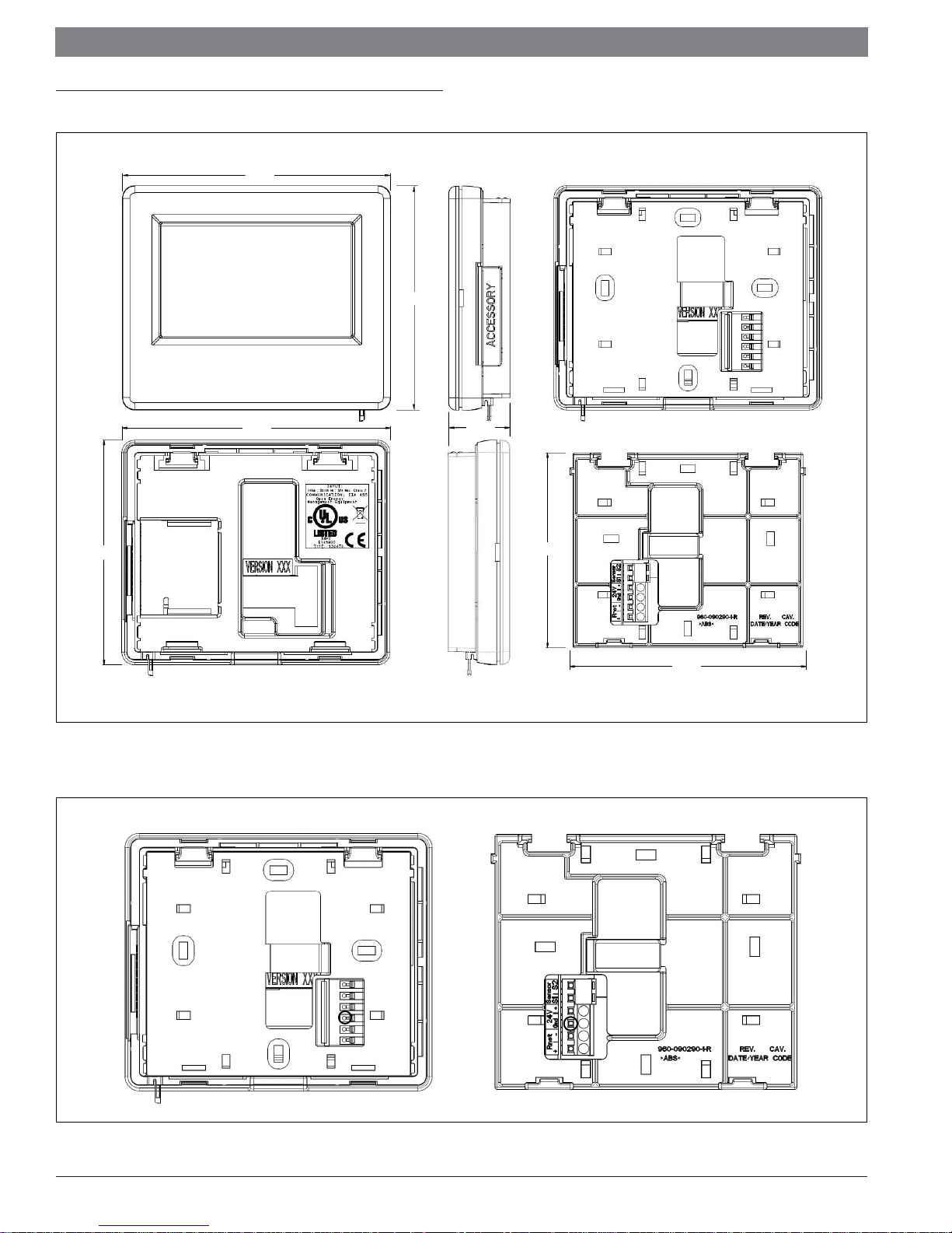
4 Physical Dimensions
4.550
5.440
5.440
Side View - Right Back View with Mounting Plate
4.550
1.242
Mounting Plate
3.938
Figure 3
Control Air M/M+ Module Termination Details
Back View with Mounting Plate
4.799
Side View - LeftBack View without Mounting Plate
Mounting Plate
Figure 4
BTC 469503103 A | 02.2019
Data subject to change
Page 8
|
8
Control Air M/M+ Water to Water Applications Installation & Operation Manual
5 Wiring
The Control Air M communicates through a Rnet connection. The Control
Air M is intended for use with a single WSHP. It can be wired using the
instructions in section 6. The Control Air M+ communicates through a
BACnet MS/TP connection. The Control Air M+ is intended for use with up
to 50 WSHP's on an exisiting network.
5.1 Recommended Wiring Scheme
Connect this wire: To this terminal on the Control Air M:
Red 24 VAC (R)
Black 24 VAC (C)
White Rnet+
Blue Rnet-
Table 2 Power Wiring
2-conductor wire 18 AWG for distances up to 100 feet. All transformer
secondaries must be grounded. Wiring connections must be in
accordance with NEC and local codes. All wiring and mounting screws
must be fi eld supplied.
5.2 Rnet Wiring Specifi cations
NOTICE:
Use the specified type of wire and cable for maximum
signal integrity.
Description Value
Cable
Conductor 22 AWG (7x0096) bare copper
Maximum length 500 feet (152 meters)
Recommended coloring Jacket: White
4 conductor, unshielded, or unshielded
CMP, plenum rated cable
6 Connection
6.1 Communicate Using a Tablet Through Virtual Control Air M and M+
In lieu of using the module to interface with the controller, a connection
may be established at the local access port of the controller to perform
test and balance operations or to make changes to any device on the networ k.
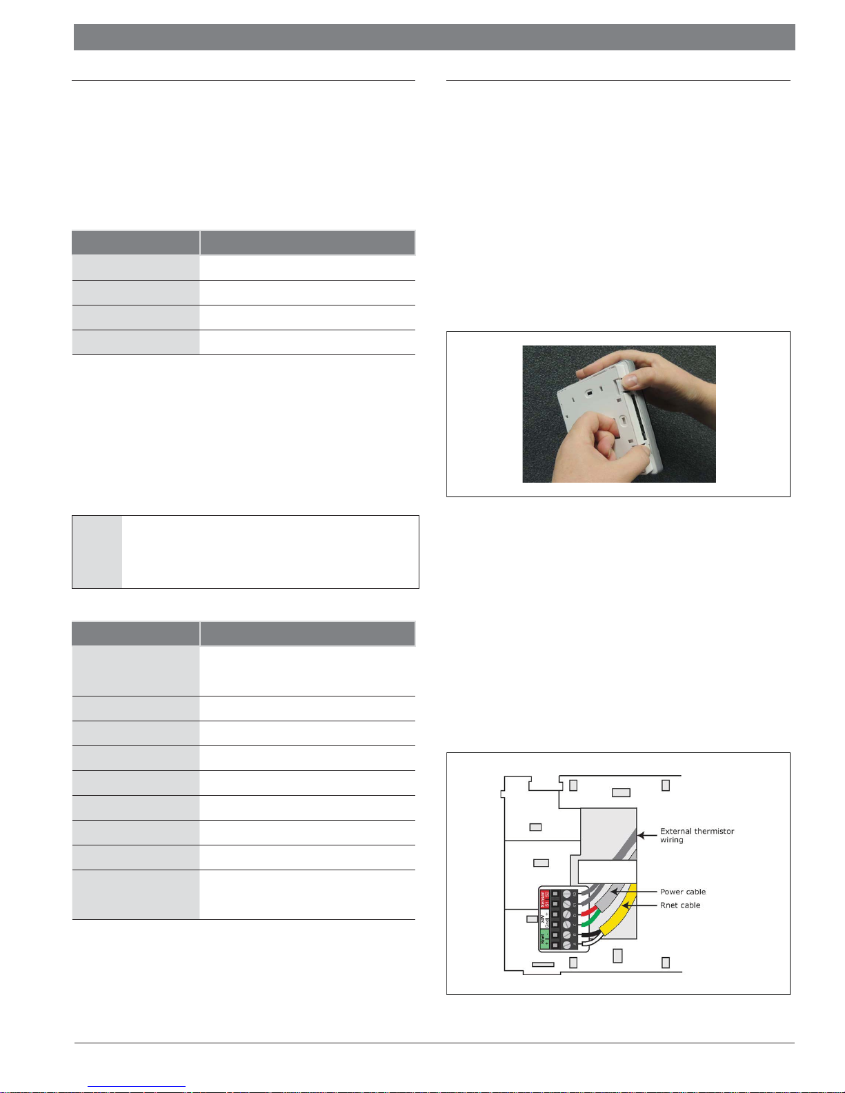
6.2 To Wire and Mount the Control Air M/M+
1. Remove the backplate from the Control Air M/M+
a. Hold the Control Air M/M+ as shown in the picture below.
b. While fi rmly pressing the 2 tabs on top of the Control Air M/
M+, pull on the backplate with your index fi nger until the
backplate releases from the Control Air M/M+.
Figure 5
2. Pull the communication cable, power cable, and external
thermistor wiring (if applicable) through the large hole in the center
of the backplate.
3. Partially cut, then bend and pull off the outer jacket of the Rnet
cable(s). Do not nick the individual wire insulation.
4. If wiring 1 cable to the Control Air M/M+, cut the shield wire off at
the outer jacket, then wrap the cable with tape at the outer jacket
to cover the end of the shield wire. If wiring 2 cables in a daisychain confi guration, twist together the shield wires, then wrap the
shield wires with tape.
5. Strip about 0.25 inch (0.6 cm) insulation from the end of each
wire.
6. Connect wiring to the Control Air M/M+ as shown in Figure 6.
UL temperature 32–167°F (0–75°C)
Voltage Limited Listing 300 VAC, power UL: NEC CL2P, or better
Insulation Low-smoke PVC (or equivalent)
Color Code Black, white, green, red
Shielding
Table 3
If shielded, Aluminum/Mylar shield
(100% coverage) with TC drain wire
Figure 6
02.2019 | BTC 469503103 AData subject to change
Page 9
Installation & Operation Manual Control Air M/M+ Water to Water Applications | 9
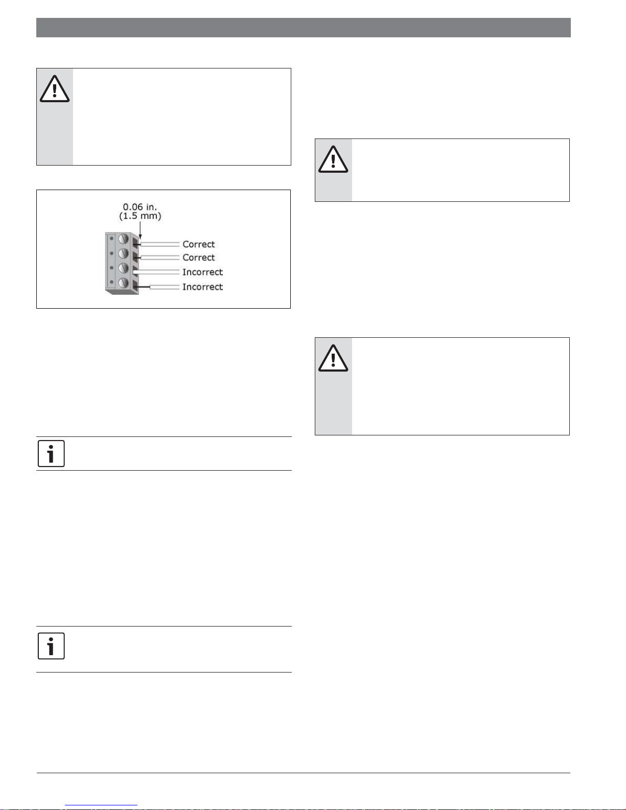
6.3 Additional Information on Connecting Control Air
CAUTION: ELECTRIC SHOCK HAZARD
Allow no more than 0.06 inch (1.5 mm) bare
communication wire to protrude. If bare
communication wire contacts the cable's foil shield,
shield wire, or a metal surface other than the
terminal block, the device may not communicate
correctly.
Figure 7
M/M+ to a Controller
Connect the Control Air M/M+ module (or Android tablet if using Virtual
Control Air M/M+) to the serial port on the DDC controller as indicated
below.
CAUTION: ELECTRIC SHOCK, INJURY HAZARD
If the equipment is used in a manner not specified
by the manufacturer, the protection provided by
the equipment may be impaired.
Mounting
The Control Air M/M+ must be mounted within the building interior. You
can mount the Control Air M/M+:
In a panel with the controller or on the panel door
On a wall up to 500 feet from the controller
Wiring
The Control Air M/M+ requires a 24 Vac power supply. It is not powered by
the Rnet.
7. Attach the backplate to the wall or panel. If mounting in or on a
panel:
a. Drill two 3/16 inch (4.8 mm) pilot holes in the panel.
b. Attach backplate using pan head 6-32 x 3/8" to l/2" long
machine screws. Do not overtighten screws to prevent
damage to plastic housing.
It is recommended to use Loctite 220 on screw threads if the
Control Air M/M+ will be subject to vibration.
8. Attach the Control Air M/M+ to the backplate:
a. Place the bottom of the Control Air M/M+ onto the backplate
by aligning the 2 slots on the Control Air M/M+ with the tabs
on the backplate.
b. Push the Control Air M/M+ onto the backplate until the tabs
at the top of the Control Air M/M+ snap onto the backplate.
9. Turn off the controller's power.
10. Connect the other end of the Rnet wiring to the controller's Rnet
port or to a zone sensor.
- Insert the shield wire with the ground wire into the controller's
GND terminal.
- Use the same polarity throughout the Rnet or MS/TP.
CAUTION: ELECTRIC SHOCK HAZARD
The Control Air M/M+ can share a power supply
with the DDC controller as long as you:
1. Maintain the same polarity.
2. User the power supply only for DDC
controllers.
You can also wire an external 10 kOhm, Type II thermistor to the Control
Air M/M+. See External sensor resistance requirements (Table 6, page
13).
11. Connect power wiring to a 24 Vac power supply.
12. Turn on the controller's power.
BTC 469503103 A | 02.2019
Data subject to change
Page 10

|
10
Control Air M/M+ Water to Water Applications Installation & Operation Manual
Establishing Communication
Plug the USB-L cable to the USB (Bosch part number 8733-927-403)
to USB micro adapter (fi eld supplied) and then to the Android tablet and
controller before launching Virtual Control Air M/M+ (Equipment Touch
(OEM) app). The DDC controller must be connected to a 24 VAC source
and powered on.
Not provided
by Bosch
Control Air
M/M+
connector
8733-927-403
Figure 8
Figure 9
02.2019 | BTC 469503103 AData subject to change
Page 11

Installation & Operation Manual Control Air M/M+ Water to Water Applications | 11
7 How to Navigate Screens in Control Air M/M+
7.1 Login
The following displays if the screen you selected requires a password.
Enter your password, then touch Done.
Figure 10
Each screen is programmed with one of the following password levels:
A screen having this
password level…
User
A user logged in with the User, Admin, or
Can be accessed by…
Factory password
7.2 Alarms
The Alarm screen allows the user to view up to 100 events starting with
the most recent. It also allows user to see which points have gone into
alarm and retuned to normal as well as the ones that have been manually
cleared.
Figure 11
7.3 Trends
Admin
A user logged in with the Admin or Factory
password
Factory A user logged in with the Factory password
No password Anyone
Table 4
The default password for a new Control Air M/M+ is 0000.
You can change passwords on the Control Air M/M+ by going to
Touchscreen Setup > Passwords screen.
You log out on the Setup screen.
Figure 12
This screen can be accessed from the Help Screen on the Service page
(Home -> Service -> Help -> Trends). It allows the end user to view trends
for points that have trending enabled.
Figure 13
BTC 469503103 A | 02.2019
Data subject to change
Page 12

|
12
Control Air M/M+ Water to Water Applications Installation & Operation Manual
8 To Update the Control Air M/M+’s Firmware
The Control Air M/M+ has a USB port at the bottom that allows you to
update the device's fi rmware from a USB fl ash drive.
8.1 Prerequisite
The USB fl ash drive must be formatted as FAT, FAT16, or FAT32. To verify,
right-click the fl ash drive in Windows Explorer, then select Properties.
File system should show FATxx. If File system shows NTFS or anything
else, you must reformat the drive. Right-click the fl ash drive, then select
Format. In the File system fi eld, select FAT (Default), then click Start.
NOTICE:
Follow the steps below in order. If you select Reload
Firmware (step 3) on the display before you insert
the USB drive (step 2), the touchscreen will become
inoperable.
8.2 To Update the Firmware
1. Create a folder on the fl ash drive called Touch, then put the
ETxxxxxx.hex fi le in the folder.
2. Plug the fl ash drive into the Control Air M/M+'s USB port.
3. From the System screen, touch Setup > Touchscreen Setup >
Reload Firmware.
4. A warning message appears. Touch Yes to continue.
5. The following series of messages appear:
Verifying Firmware Image
Reading Firmware Image from USB
Installing Application
Verifying Firmware Image.
6. When the Home screen displays, remove the fl ash drive.
7. Insert the fl ash drive into the USB port at the bottom of the Control
Air M/M+.
8. Cycle power to the Control Air M/M+.
If… Then you should…
You cannot get to
the Touchscreen
You need to
quickly update
the fi rmware on
several Control Air
M/M+ devices
You want to carry
your Control Air
M/M+ from site
to site.
Your Control
Air M/M+ has a
unrecoverable
error from site
to site
The Control
Air M/M+ does
not respond
correctly to the
location where
you touched the
screen
Table 5
Reload the fi rmware 01
Reload the fi rmware - Put the
new fi rmware in the Touch
folder with the reset.dat fi le
Reset factory defaults 04
Calibrate the touchscreen 08
Function
number
01
8.3 Resetting the Control Air M/M+
You can create a reset.dat fi le and put it on a USB fl ash drive to reset some
of the Control Air M/M+’s functionality.
Prerequisite
The USB fl ash drive must be formatted as FAT, FAT16, or FAT32. To verify,
right-click the fl ash drive in Windows Explorer, then select Properties.
File system should show FATxx. If File system shows NTFS or anything
else, you must reformat the drive. Right-click the fl ash drive, then select
Format. In the File system fi eld, select FAT (Default), then click Start.
1. Insert the USB fl ash drive into your computer.
2. Create a folder on the fl ash drive named Touch.
3. In a text editor such as Notepad, start a new fi le.
4. In the fi le, type a function number from the table below.
5. Save the fi le to the fl ash drive's Touch folder with the name reset.
dat.
6. For function 01 or 02, copy any updated fi rmware .hex fi le or .stv
fi le in the Touch folder.
02.2019 | BTC 469503103 AData subject to change
Page 13

Installation & Operation Manual Control Air M/M+ Water to Water Applications | 13
8.4 Compliance
FCC Compliance
This equipment has been tested and found to comply with the limits
for a Class A digital device, pursuant to Part 15 of the FCC Rules.
These limits are designed to provide reasonable protection against
harmful interference when the equipment is operated in a commercial
environment. This equipment generates, uses, and can radiate radio
frequency energy and, if not installed and used in accordance with
the instruction manual, may cause harmful interference to radio
communications. Operation of this equipment in a residential area is likely
to cause harmful interference in which case the user will be required to
correct the interference at his own expense.
NOTICE: HARMFUL INTERFERENCE HAZARD
Changes or modifications not expressly approved
by the responsible party for compliance could void
the user’s authority to operate the equipment.
CE Compliance
NOTICE: HARMFUL INTERFERENCE HAZARD
This is a Class A product. In a domestic
environment, this product may cause radio
interference in which case the user may be
required to take adequate measures.
External sensor resistance requirements
Temp (°C) Temp (°F) Resistance (Ohms)
-40 -40 335,651
-35 -31 242,195
-30 -22 176,683
-25 -13 130,243
-20 -4 96,974
-15 5 72,895
-10 14 55,298
-5 23 42,315
0 32 32,651
5 41 25,395
10 50 19,903
15 59 15,714
20 68 12,494
25 77 10,000
30 86 8,056
35 95 6,530
Table 6
40 104 5,325
45 113 4,367
50 122 3,601
55 131 2,985
60 140 2,487
65 149 2,082
70 158 1,752
BTC 469503103 A | 02.2019
Data subject to change
Page 14

|
14
Control Air M/M+ Water to Water Applications Installation & Operation Manual
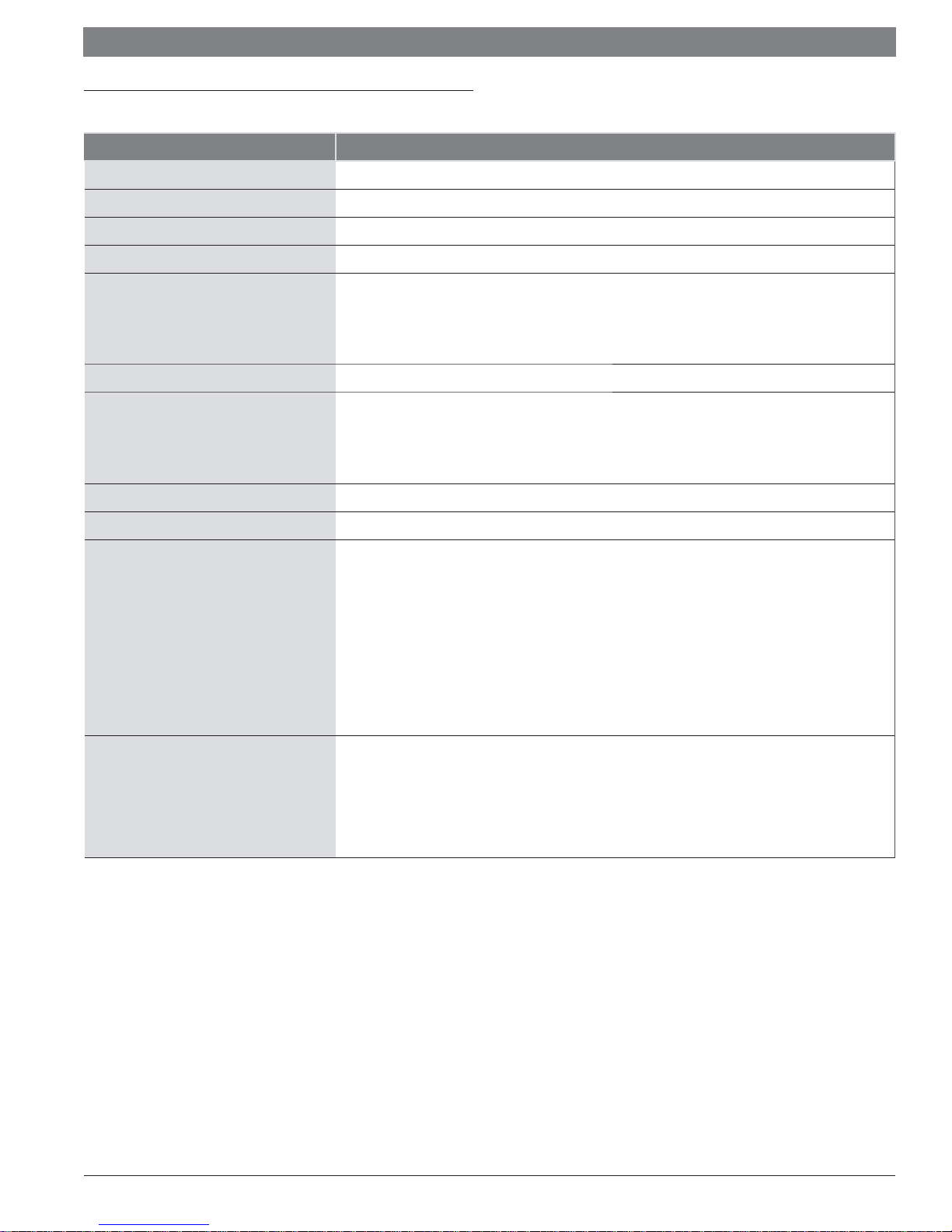
9 The Control Air M and M+ Screens
9.1 Units Status Screen/Home Page
The Unit Status screen (Figure 14) is the home page for the Control Air
M, and shows the main menus/categories of the software the user can
interface with on the devices.
Settings – For an installer, these settings allow for changes to
the device, as well as unit configuration at start-up.
Service – For a service technician, this menu allows a user to
diagnose or troubleshoot the unit.
The screen provides valuable unit diagnostic data - entering and leaving
water temperatures, states of the compressors, Reversing valve, Pump.
It gives the user the ability to change the temperature units between
Fahrenheit and Celsius. The header of the screen is common to most
screens.
Figure 14
9.2 Settings Screen
The Settings page allows the user to access one of the following pages:
Unit Settings
Device Settings
Alarm Settings
*Pumps
Temperature
Schedule
Setpoints
*Lead/Lag
9.2.1 Unit Settings Screen
This screen can be accessed from the Settings menu. This menu allows
the commissioning agent to setup or modify operational parameters of the
unit.
Once all operational parameters are confi gured, these settings may be
saved and archived to fl ash memory by selecting the Save Settings checkbox.
Figure 16
Occupancy Command
Under the Unit Settings screen, this parameter is used to select the
control source that will provide the occupancy command to the unit. The
options for this variable are the following:
Digital Input
Local Schedule
BAS Command
Manual Override
Throughout the setup process, by selecting diff erent boxes, this
is how you advance to the next setup screen if available, while
the back arrow is used to backtrack to previous screens.
Digital Input: The Digital Input option may be selected if the unit
occupancy is required to be controlled remotely via a switch (dry
contact) or other binary input. The connection (typically from a room
occupancy sensor) should be made in IN-1 of the controller. Choosing
this setting allows the unit to be placed in occupied mode once the
input is shorted to ground, and in unoccupied mode once the input is
opened.
*
If confi gured in Unit Settings.
Figure 15
Local Schedule: Schedule runs the unit on a local, modifi able
schedule, which cannot be accessed over a network. The occupancy
schedule for heating or cooling can be set according to the morning,
daytime, and night time settings for each day of the week. The option
will allow the unit to run on an 8:00 AM to 5:00 PM default schedule
everyday if the unit is to be started up during the construction phase of
the project. See the Schedule Screen for more information.
02.2019 | BTC 469503103 AData subject to change
Page 15

Installation & Operation Manual Control Air M/M+ Water to Water Applications | 15
BAS Command:
The unit factory default for the Occupancy Command
parameter is set to BAS Command. A qualifi ed technical agent may change
the parameter to be BAS Command, if diff erent from the default setting. This
option will enable the unit to be commanded from the BAS Server. The unit
is ready for BAS integration once this parameter is set up, and it can then
be commanded to occupied or unoccupied via the BAS by writing to the
Occupancy Status integration point (refer to Integration Points List document).
Manual Override: If the unit is intended to run all the time it can be set
to Manual Override, which will override the schedule and set the unit
into occupied mode indefi nitely, until the Manual Override option is
deselected.
Compressor Stages
This parameter allows the user to choose the number of compressors and stages
for the application. This parameter is typically set up from the factory to match the
unit confi guration and should only be changed by a qualifi ed technician.
Ensure the compressor confi guration is set accurately as this
selection will determine the code structure for reporting
compressor safety alarms from the Unit Protection Module
(UPM) to the controller. The fault codes for a 1 compressor 1
stage unit are diff erent from that for a 2 compressor 2 stage unit.
Mode Selection Method
This setting is similar to a thermostat mode select feature, which gives the user the
option of setting the unit mode. The options are: Heat, Cool, Off , Auto and Digital
input. When operating on Digital Input mode the unit will change from heat to cool
by using the state of the digital input (IN6) on controller as follows:
Off = Heat
On = Cool
This feature is typically used when the unit is not confi gured into a BAS network.
However, if there is a BAS network, it is recommended to operate the unit using
the integration points.
Figure 17
2 Compressor 2 Stages: This value is selected when unit has 2 compressors
and each compressor will operate as an independent stage.
1 Compressor 2 Stages: This value is selected when unit has 1 compressor
that has two independent stages. This is the default setting from the factory.
1 Compressor 1 Stage: This value is selected when unit has 1 compressor with
only 1 stage of operation.
Night Setback Enable:
This parameter allows users to enable or disable night setback feature.
Enabling Night setback will operate the unit under the following setpoints
when it enters the unoccupied state.
74°F (adj.) Cooling setpoint.
85°F (adj.) Heating setpoint.
Disabling it puts the unit in an OFF state and the unit will not try to meet
any setpoints.
Aux Output Enable
This parameter can be used to energize the Auxiliary output (DO-5). This
is a manual setting and DO-5 is not confi gured to support any device in
particular. Its a simple On/Off function for D0-5 and is Off by default.
Use Optional Pump Output
When this parameter is set to Yes, BO-1 can be used for pump output.
Selecting Yes also enables the "Pump" confi guration page on the Settings
screen.
BTC 469503103 A | 02.2019
Data subject to change
Page 16

|
16
Control Air M/M+ Water to Water Applications Installation & Operation Manual
9.2.2 Device Settings Screen
Figure 18
The Device Settings menu allows the user to adjust or reset any settings
on the actual Control Air M/M+ module.
On this screen the BACnet® ID will be displayed. This value can be
changed, however, it is not recommend to change this parameter
arbitrarily as it may cause network problems.
Always consult with Network Administrator (Front End company) before
changing the controllers BACnet® ID as it may interfere with other devices
in the network.
Two main sub menus are available on this screen:
Controller
Touchscreen
9.2.2.1 Controller Screen
9.2.2.1.2 Communication
This screen lets you edit the information below for the controller.
Figure 21
Touch a fi eld to tap in new information.
— BACnet Device Instance – number
— Auto Generate Device ID – Enter No or Yes
You can edit the following fi elds that pertain to the controller's MS/
TP network:
— Max Masters - Set this to the highest MAC
address (up to 127) on the MS/TP network. If
you later add a device with a higher address, you
must change this field to that new address.
— Max Info Frames - Specifi es the maximum
number of information messages a controller
may transmit before it must pass the token to the
next controller. CAUTION Increasing this number
allows the controller to transmit more messages
while it has the token, but it also increases the
overall time it takes for the token to pass through
the network.
Figure 19
This screen provides access to the device Module Setup menu, that
provides the end-user the ability to set the time/date, update device
communication information, and access to the Time Master page.
9.2.2.1.1 Set Time and Date
Touch the time or date fi eld to edit it.
Figure 20
For a router, set this value to a high number such as 200
In non-router controllers, use the following formula to
calculate this value: [2 - (devices * (.002 + (80/baud))] /
[(600/baud) * devices] = Max Info Frames
For example, if the network has 15 devices at 19200 baud,
Max Info Frames would be 4.
You may need to increase the result of the formula for controllers
that need to communicate many values to other devices.
02.2019 | BTC 469503103 AData subject to change
Page 17

Installation & Operation Manual Control Air M/M+ Water to Water Applications | 17
9.2.2.1.3 Router
Lets you view or edit the router's ARC156, MS/TP, or Ethernet
network number.
Figure 22
Touch a fi eld to tap in the new number on the keypad.
9.2.2.1.4 IP
Lets you view or edit network addresses and the UDP Port.
9.2.2.1.5 Time Master
If the controller can be a BACnet Time Master, this screen lets you
confi gure how it sends time synchronization broadcasts.
Figure 24
Time Sync Mode - Tap in the number below that represents your
selection:
— 0 = No Broadcast - The controller will not act as Time
Master.
— 1 = Local Broadcast - If it doesn't already exist, a
BACnet address with network number and MAC address
length both set to zero is added to the controller's Time
Synchronization Recipients list found on the driver's
Device page in WebCTRL®. The controller will then send
time broadcasts only to controllers on its ARCnet or MS/
TP network.
Figure 23
Touch a fi eld to tap in the new number on the keypad.
— 2 = Global Broadcast - If it doesn't already exist, a global
address with network number set to 65535 and MAC
address length set to zero is added to the controller's
Time Synchronization Recipients list found on the driver's
Device page in WebCTRL®. The controller will then send
time broadcasts to all its connected networks.
Time Sync Interval - Enter how often local or global time
broadcast should be sent (1-9999 minutes). If Time Sync Interval
is set to zero, no time sync messages are sent.
If the controller looks through its Time Synchronization Recipient
List and fi nds an entry with MAC address length set to zero and
network number set to 65535, the controller's BACnet Time
Master mode is set for Global Broadcast. If there is no global
broadcast entry in the recipient list, the controller then looks for
a local broadcast address (MAC address length set to zero and
network number set to zero or to the same network number as
the module's). If such an entry is found, the BACnet Time Master
mode is set for Local Broadcast. Otherwise, the mode defaults to
Disabled/None.
BTC 469503103 A | 02.2019
Data subject to change
Page 18

|
18
Control Air M/M+ Water to Water Applications Installation & Operation Manual
9.2.2.2 Touchscreen Screen
Figure 25
This screen provides the end-user the ability to edit and modify the
touchscreen settings.
Touch a button to go to one of these screens:
Screen Description
About Displays information about the touchscreen fi rmware
Inactivity
Timeout
Lets you defi ne how long the Control Air M can have
no activity before returning to the Standby screen and
logging out the user. Set to 0 to deactivate this feature
9.2.3 Alarms Settings Screen
The Alarm Settings screen can be accessed from the home page
through the Settings menu. This screen allows the user to adjust heat
pump unit alarm settings, including:
Set values for alarm trip limits on leaving water temperature.
Set values for entering water temperature differentials
Set Pump and compressor(s) runtime trip values.
Figure 26
Lets you set up the Control Air M temperature
Sensor
Setup
and humidity sensors. See Using Control Air M’s
temperature and humidity sensors to control
equipment
Displays a one-minute count-down timer so that you
Clean
Screen
can clean fi ngerprints from the display window without
touching something that would aff ect equipment
operation.
Key Click
Off /On
Alarm
Sound
Off /On
Reload
Firmware
Touch Key Click Off to turn off the sound when you
touch a fi eld or button. Touch Key Click On to turn on
the sound
Touch Alarm Sound Off to turn off the alarm notifi cation
sound or touch Alarm Sound On to turn on the sound.
An alarm will generate a sound only if it is set up by
Bosch
Erases the current fi rmware so that you can load new
fi rmware through the USB port. See To update the
Control Air M/M+'s fi rmware
Passwords Let you change the User or Admin password, if allowed.
Figure 27
Lets you recalibrate the Control Air M/M+ by touching
Calibrate
Touch
Panel
targets. The device is calibrated in the factory, but
time, temperature, or handling could aff ect the
calibration. Recalibrate the screen if you touch it in one
location and it responds as if you touched it in another.
Table 7
02.2019 | BTC 469503103 AData subject to change
Page 19

Installation & Operation Manual Control Air M/M+ Water to Water Applications | 19
9.2.4 Pumps
This screen can be accessed from the Home page through the Setting
Menu. This screen Allows the user to view and/or adjust the following
parameters:
Run Continuously in Occupied mode:This parameter when
set to "Yes" runs the pump continuously in the occupied mode
and if set to "No", cycles with the compressor
Pump Output: This parameter does not indicate is the pump
output is actually energised, instead indicates if there is a
pump call.
Pump Start Counter (total): This value indicates how many
times in total the pump was started after its corresponding
reset.
Pump Start Counter (Last hr): This value indicates how many
times in the last hour the pump was started.
9.2.6 Setpoints
This screen can be accessed from the Settings screen. It allows the user to
adjust the following setpoints and diff erentials
Occupied heating and cooling setpoints
Unoccupied heating and cooling setpoints
Heat/Cool Setpoint differential
Heat/Cool Stage 2 setpoint differential
Auto Changeover setpoint and deadband
Figure 30
Figure 28
9.2.5 Temperature
The Temperature Screen can be accessed from the home page through
the Settings menu. This screen allows the user to view the following
temperatures and temperature setpoints.
Entering water temperature
Leaving water temperature
Auto changeover temperature
Effective cooling setpoint
Effective heating setpoint.
Figure 31
Figure 29
BTC 469503103 A | 02.2019
Data subject to change
Page 20

|
20
Control Air M/M+ Water to Water Applications Installation & Operation Manual
9.2.7 Schedule Screen
The Schedule menu can be accessed from the home page through the
Settings menu. This screen allows the user to view, add, edit, or delete
BACnet schedules in the controller.
Figure 32
The controller comes with the following default schedule:
Day of Week Time Mode
MON-FRI 8:00AM - 5:00PM Occupied Mode
SAT 7:00AM - 3:00PM Occupied Mode
SUN 10:00AM - 1:00PM Occupied Mode
Week View
Figure 34
Which days of the week shown have schedules (indicated by
green bars).
If you see Schedule editing disabled at the bottom of the screen
instead of Add Schedule, scheduling is being done through
another application and is disabled for the Control Air M+.
Touch a day to see the schedule(s) for that day. In the screen
below, touch a schedule’s name or green bar (not the Eff ective
Schedule bar) to edit or delete the schedule.
Table 8
Viewing Schedules
Month View (default)
Figure 33
The schedule screen is confi gured to display the monthly view by default.
To change to weekly view, click drop down option and change accordingly.
Figure 35
The Eff ective Schedule is the combined result of the day's
schedule(s).
You cannot edit a schedule's Type (Dated, Weekly, Continuous),
its Priority (Normal or Override), or whether the schedule is an
ON Schedule or Off Schedule. If you need to change any of these
settings, delete the schedule, and then make a new one.
02.2019 | BTC 469503103 AData subject to change
Page 21

Installation & Operation Manual Control Air M/M+ Water to Water Applications | 21
Creating Schedule
Figure 36
In the above image there is no schedule for the weekend (Sat/Sun). To
create a schedule for every Saturday (Occupied from 7 AM to 3 PM),
click Add schedule.
Figure 37
Touch the Schedule Name fi eld, and enter a unique name (for Example:
Saturdays). Select one (ON for this example) of the following:
ON Schedule for an occupied period
ON Schedule only–Select one (normal for this example) of the
following:
Normal for a typical occupied period
Override for a occupied period that is to override an OFF
schedule.
Touch Next to defi ne the criteria for the type of schedule you selected
earlier in the scheduling process.
Figure 38
If you have a date range confi gure accordingly. Touch Save when
fi nished.
Editing/Deleting Schedules
Open the schedules screen from the Settings page. To delete or edit the
Saturdays schedule (for example), click on View schedule drop down
and select week view. Now Click on the green bar for a Saturday.
OFF Schedule for an unoccupied period that is to override
an ON schedule. For example, a holiday schedule that is to
override a weekly schedule.
Touch the Type fi eld, then select one (weekly for this example) of the
following:
Select… To use the schedule…
For a specifi ed period of time between a start and
Dated
end date. For example, 7:00 am to 7:00 pm every day
between July 1st and July 22.
Weekly
Every week on the specifi ed days. For example, every
Monday through Friday, 8:00 am to 5:00 pm.
Continuously between 2 specifi ed dates/times, For
Continuous
example, a non-stop schedule that starts June 1st at
12:00 am and ends August 31st at 11:50 pm.
Table 9
Figure 39
Click Delete to Delete this schedule,or modify as needed. To add
another schedule (period) to the current schedule, click add period. A
weekly schedule can have multiple periods.
For example, the fi rst period could be every Saturday 7:00AM to
3:00PM. The second period could be every Saturday, 6:00PM to
8:00PM.
BTC 469503103 A | 02.2019
Data subject to change
Page 22

|
22
Control Air M/M+ Water to Water Applications Installation & Operation Manual
9.2.8 Lead/Lag Screen
This screen is accessed from the Setting screen and allows the user to
confi gure the compressor rotation. This screen can only be accessed if the
unit has 2 separate compressors and i confi gured accordingly in the unit
settings screen. Under this menu, one can view and adjust the following:
Demand: This parameter displays how many compressors/
compressor stages are being called.
Compressor rotation frequency: This parameter gives the user
the option to set the frequency at which the compressors are
switched from lead to lag or vice-versa. Based on this selection the
user can set the next parameter value accordingly
Figure 40
9.3 Service Screen
The Service menu allows the qualifi ed technician to adjust or reset any
settings on the WSHP, and effi ciently troubleshoot and correct issues on
the unit. Under this menu, one can scroll up/down to view and adjust the
following:
Analog Inputs
Binary Inputs/Outputs
Figure 42
Figure 41
Figure 43
Figure 44
Figure 45
02.2019 | BTC 469503103 AData subject to change
Page 23

Installation & Operation Manual Control Air M/M+ Water to Water Applications | 23
9.3.2 UPM Status Screen
The UPM Status screen can be accessed from the home
Screen via the Service Menu. Once an alarm is received via pulse
feedback from the UPM board, it is displayed in the screen as shown
below. From this screen the user may reset the UPM board after it has
enter the lockout mode by navigating to “Reset UPM now?” selecting yes.
Figure 46
9.3.1 Heat/Cool Screen
The Heating/Cooling screen can be accessed from the Home screen
through the Service menu. From the Heating/ Cooling screen the user can
see the actual state of the diff erent points that are involved and needed
Figure 49
for the cooling and heating operation respectively.
The runtime hours and counters for the compressors are displayed and
can be reset by navigating selecting and changing the particular value.
Figure 47
Figure 48
BTC 469503103 A | 02.2019
Data subject to change
Page 24

|
24
Control Air M/M+ Water to Water Applications Installation & Operation Manual
9.3.3 Help Screen
Figure 50
The Help screen can be accessed from the home Screen via the Service
Menu. From this screen the user is able to access the software version of
the controller to which they are connected.
Other information on this screen include the controller part number and
unit serial number. This information will be useful whenever technical
support is contacted, or may be required to download the correct manuals
or integration point list fi les from our website. The technical support
phone numbers can also be found in this screen.
In addition, troubleshooting tips as well as confi guration help tips may
also be accessed from this screen.
Figure 51
Figure 52
02.2019 | BTC 469503103 AData subject to change
Page 25

Installation & Operation Manual Control Air M/M+ Water to Water Applications | 25
BTC 469503103 A | 02.2019
Data subject to change
Page 26

|
26
Control Air M/M+ Water to Water Applications Installation & Operation Manual
02.2019 | BTC 469503103 AData subject to change
Page 27

Installation & Operation Manual Control Air M/M+ Water to Water Applications | 27
BTC 469503103 A | 02.2019
Data subject to change
Page 28

United States
Bosch Thermotechnology Corp.
65 Grove Street
Watertown, MA 02472
Tel: 866-642-3198
Fax: 603-965-7581
www.boschheatingandcooling.com
BTC 469503103 A | 02.2019
 Loading...