

Page 1
Service instructions for contractors
Control unit
Control 8313
0010004580-001
6720859567 (2017/03) GB/AU
Page 2

Table of contents
Table of contents
1 Explanation of symbols and safety instructions . . . . . . . . . . . 3
1.1 Explanation of symbols . . . . . . . . . . . . . . . . . . . . . . . . . . 3
1.2 Safety precautions . . . . . . . . . . . . . . . . . . . . . . . . . . . . . . 3
2 Product Information . . . . . . . . . . . . . . . . . . . . . . . . . . . . . . . . . . 5
2.1 Declaration of Conformity . . . . . . . . . . . . . . . . . . . . . . . . 5
2.2 Open Source Software. . . . . . . . . . . . . . . . . . . . . . . . . . . 5
2.3 Product data for energy consumption. . . . . . . . . . . . . . . 5
2.4 Tools, materials and miscellaneous parts . . . . . . . . . . . . 5
2.5 Scope of delivery . . . . . . . . . . . . . . . . . . . . . . . . . . . . . . . 5
2.6 Accessories . . . . . . . . . . . . . . . . . . . . . . . . . . . . . . . . . . . 5
2.7 Product Description. . . . . . . . . . . . . . . . . . . . . . . . . . . . . 5
2.8 Determined use . . . . . . . . . . . . . . . . . . . . . . . . . . . . . . . . 5
3 Modules and their function. . . . . . . . . . . . . . . . . . . . . . . . . . . . . 6
3.1 Fitted modules . . . . . . . . . . . . . . . . . . . . . . . . . . . . . . . . . 6
3.1.1 Notice regarding fitted modules . . . . . . . . . . . . . . . . . . . 6
3.2 BCT531 (HMI) user interface . . . . . . . . . . . . . . . . . . . . . 6
3.3 Central module ZM5313 . . . . . . . . . . . . . . . . . . . . . . . . . 7
3.4 NM582 power supply module. . . . . . . . . . . . . . . . . . . . . 7
3.5 Base module BM592 . . . . . . . . . . . . . . . . . . . . . . . . . . . . 7
3.6 FM-MM function module (accessory) . . . . . . . . . . . . . . . 7
3.7 FM-MW function module (accessory). . . . . . . . . . . . . . . 7
3.8 FM-SI function module (accessory) . . . . . . . . . . . . . . . . 7
3.9 FM-RM function module (accessory) . . . . . . . . . . . . . . . 7
4 Standards, regulations and directives . . . . . . . . . . . . . . . . . . . 7
5 Installation . . . . . . . . . . . . . . . . . . . . . . . . . . . . . . . . . . . . . . . . . . 8
5.1 Assembly . . . . . . . . . . . . . . . . . . . . . . . . . . . . . . . . . . . . . 8
5.2 Overview of controller . . . . . . . . . . . . . . . . . . . . . . . . . . . 8
5.3 Electrical connection . . . . . . . . . . . . . . . . . . . . . . . . . . . . 8
5.4 User interface connections (HMI) . . . . . . . . . . . . . . . . . . 9
5.5 Connecting the heat source to the control unit . . . . . . . 9
5.5.1 Connection to the SAFe. . . . . . . . . . . . . . . . . . . . . . . . . . 9
5.5.2 Connection to a EMS heat source . . . . . . . . . . . . . . . . .10
5.5.3 Connection via the Modbus interface . . . . . . . . . . . . . . 10
5.6 Connection to other control units in the 8000
series or to a network. . . . . . . . . . . . . . . . . . . . . . . . . . . 10
5.7 Connection of modules . . . . . . . . . . . . . . . . . . . . . . . . . 10
5.8 Connection of safety equipment and the FM-SI
module . . . . . . . . . . . . . . . . . . . . . . . . . . . . . . . . . . . . . . 10
5.9 Remote control. . . . . . . . . . . . . . . . . . . . . . . . . . . . . . . . 10
5.10 Other connections . . . . . . . . . . . . . . . . . . . . . . . . . . . . . 10
6 Operation of the control unit . . . . . . . . . . . . . . . . . . . . . . . . . . 11
6.1 Control elements of the control unit and the user
interface . . . . . . . . . . . . . . . . . . . . . . . . . . . . . . . . . . . . . 11
6.2 Function buttons and system status . . . . . . . . . . . . . . . 12
6.3 Operating and display elements of the touch
screen . . . . . . . . . . . . . . . . . . . . . . . . . . . . . . . . . . . . . . . 12
6.4 Operating the appliance . . . . . . . . . . . . . . . . . . . . . . . . 13
6.5 Modifying settings . . . . . . . . . . . . . . . . . . . . . . . . . . . . . 13
6.6 Labelling a text field . . . . . . . . . . . . . . . . . . . . . . . . . . . . 13
6.7 Labelling the text field of the FM-SI module
(accessory). . . . . . . . . . . . . . . . . . . . . . . . . . . . . . . . . . . 13
6.8 Calling up the service menu. . . . . . . . . . . . . . . . . . . . . . 14
7 Function keys of the user interface. . . . . . . . . . . . . . . . . . . . . 14
7.1 Reset key . . . . . . . . . . . . . . . . . . . . . . . . . . . . . . . . . . . . 14
7.2 Chimney sweep button (flue gas test) . . . . . . . . . . . . . 14
7.3 Key for manual operation, emergency operation . . . . . 15
8 Commissioning. . . . . . . . . . . . . . . . . . . . . . . . . . . . . . . . . . . . . . 16
8.1 Notes on commissioning . . . . . . . . . . . . . . . . . . . . . . . . 16
8.2 Control unit settings. . . . . . . . . . . . . . . . . . . . . . . . . . . . 16
8.2.1 Setting the control unit address . . . . . . . . . . . . . . . . . . 16
8.2.2 Terminating resistors . . . . . . . . . . . . . . . . . . . . . . . . . . . 16
9 Menu structure. . . . . . . . . . . . . . . . . . . . . . . . . . . . . . . . . . . . . . 17
9.1 General characteristic data . . . . . . . . . . . . . . . . . . . . . . 18
9.2 Module selection . . . . . . . . . . . . . . . . . . . . . . . . . . . . . . 18
9.3 Boiler parameters . . . . . . . . . . . . . . . . . . . . . . . . . . . . . 19
9.3.1 Basic boiler settings. . . . . . . . . . . . . . . . . . . . . . . . . . . . 19
9.3.2 Settings of the safety equipment . . . . . . . . . . . . . . . . . 20
9.4 Heating circuit data . . . . . . . . . . . . . . . . . . . . . . . . . . . . 21
9.4.1 Basic setting. . . . . . . . . . . . . . . . . . . . . . . . . . . . . . . . . . 21
9.4.2 Heating curve, operating mode. . . . . . . . . . . . . . . . . . . 23
9.4.3 Frost protection . . . . . . . . . . . . . . . . . . . . . . . . . . . . . . . 26
9.4.4 Screed drying. . . . . . . . . . . . . . . . . . . . . . . . . . . . . . . . . 26
9.5 Domestic hot water . . . . . . . . . . . . . . . . . . . . . . . . . . . . 27
9.5.1 Thermal disinfection . . . . . . . . . . . . . . . . . . . . . . . . . . . 28
9.6 Connectivity . . . . . . . . . . . . . . . . . . . . . . . . . . . . . . . . . . 28
9.7 Lock screen . . . . . . . . . . . . . . . . . . . . . . . . . . . . . . . . . . 29
10 Information on the general data main menu . . . . . . . . . . . . . 30
10.1 Submenu Minimum outdoor temperature . . . . . . . . . . 30
10.2 Building type, insulation standard submenu . . . . . . . . 30
10.2.1 Building. . . . . . . . . . . . . . . . . . . . . . . . . . . . . . . . . . . . . . 30
10.2.2 Insulation standard . . . . . . . . . . . . . . . . . . . . . . . . . . . . 30
10.3 External heat requirement. . . . . . . . . . . . . . . . . . . . . . . 31
10.3.1 Temperature 0...10 V . . . . . . . . . . . . . . . . . . . . . . . . . . 31
10.3.2 Output 0...10 V . . . . . . . . . . . . . . . . . . . . . . . . . . . . . . . 31
11 Information on the boiler parameters main menu . . . . . . . . 32
11.1 General settings regarding boiler parameters . . . . . . . 32
11.1.1 Setting up the pump function . . . . . . . . . . . . . . . . . . . . 32
11.2 Maximum shutdown temperature. . . . . . . . . . . . . . . . . 32
11.3 Information on the FM-SI module . . . . . . . . . . . . . . . . . 32
12 Information on the heating circuit data main menu . . . . . . . 33
12.1 Default settings . . . . . . . . . . . . . . . . . . . . . . . . . . . . . . . 33
12.1.1 Submenu Remote Control . . . . . . . . . . . . . . . . . . . . . . . 33
12.1.2 Submenu Third party WF control settings . . . . . . . . . . 33
12.1.3 Submenu Room temperature offset . . . . . . . . . . . . . . . 33
12.2 Temperature settings. . . . . . . . . . . . . . . . . . . . . . . . . . . 33
12.2.1 Operating modes . . . . . . . . . . . . . . . . . . . . . . . . . . . . . . 33
12.2.2 Setback types. . . . . . . . . . . . . . . . . . . . . . . . . . . . . . . . . 35
12.3 Information on the Heating curve main menu . . . . . . . 35
12.4 Submenu Screed drying . . . . . . . . . . . . . . . . . . . . . . . . 36
13 Information on the DHW data main menu . . . . . . . . . . . . . . . 36
13.1 Circulation systems . . . . . . . . . . . . . . . . . . . . . . . . . . . . 36
13.2 Submenu Thermal disinfection . . . . . . . . . . . . . . . . . . . 36
2
Control 8313 – 6720859567 (2017/03)
Page 3
Explanation of symbols and safety instructions
14 Information on the reset main menu . . . . . . . . . . . . . . . . . . . .37
15 Information on the Version main menu. . . . . . . . . . . . . . . . . .37
16 Information on the Connectivity main menu . . . . . . . . . . . . .37
16.1 Establishing a network with other Control 8000
control units . . . . . . . . . . . . . . . . . . . . . . . . . . . . . . . . . .37
16.1.1 Establishing a network . . . . . . . . . . . . . . . . . . . . . . . . . .37
16.1.2 Control unit coupling . . . . . . . . . . . . . . . . . . . . . . . . . . .38
16.2 Network connection . . . . . . . . . . . . . . . . . . . . . . . . . . . .38
16.3 Set up access to MEC Remote Portal. . . . . . . . . . . . . . .40
16.3.1 Registration of control unit. . . . . . . . . . . . . . . . . . . . . . .40
16.3.2 Accessing the MEC Remote Portal. . . . . . . . . . . . . . . . .41
16.3.3 Changing the system data . . . . . . . . . . . . . . . . . . . . . . .41
16.3.4 User settings . . . . . . . . . . . . . . . . . . . . . . . . . . . . . . . . . .42
17 Information on the function check main menu . . . . . . . . . . .43
18 Information on the lock screen main menu . . . . . . . . . . . . . . 43
19 Information on the monitor data main menu . . . . . . . . . . . . .44
19.1 SI monitor data submenu. . . . . . . . . . . . . . . . . . . . . . . .44
20 Service . . . . . . . . . . . . . . . . . . . . . . . . . . . . . . . . . . . . . . . . . . . . .44
20.1 Information on the control unit main menu. . . . . . . . . . 44
20.2 Service adapter (accessory) . . . . . . . . . . . . . . . . . . . . .44
20.3 Control unit update. . . . . . . . . . . . . . . . . . . . . . . . . . . . .44
20.4 Faults. . . . . . . . . . . . . . . . . . . . . . . . . . . . . . . . . . . . . . . .44
20.4.1 Fault display . . . . . . . . . . . . . . . . . . . . . . . . . . . . . . . . . .44
20.5 Fault history . . . . . . . . . . . . . . . . . . . . . . . . . . . . . . . . . .45
20.6 Troubleshooting . . . . . . . . . . . . . . . . . . . . . . . . . . . . . . .45
21 Cleaning the control unit. . . . . . . . . . . . . . . . . . . . . . . . . . . . . .48
22 Environmental protection/disposal. . . . . . . . . . . . . . . . . . . . .48
23 Appendix . . . . . . . . . . . . . . . . . . . . . . . . . . . . . . . . . . . . . . . . . . .49
23.1 Technical data. . . . . . . . . . . . . . . . . . . . . . . . . . . . . . . . .49
23.1.1 Control unit specifications . . . . . . . . . . . . . . . . . . . . . . .49
23.1.2 FM-MM function module specifications . . . . . . . . . . . .49
23.1.3 FM-MW function module specifications . . . . . . . . . . . .49
23.1.4 FM-SI function module specifications . . . . . . . . . . . . . .49
23.2 Sensor curves . . . . . . . . . . . . . . . . . . . . . . . . . . . . . . . . .50
23.2.1 Pressure drop values for outside, room, flow and
hot water temperature sensors . . . . . . . . . . . . . . . . . . .50
23.2.2 Pressure drop values for boiler water temperature
sensor and flue gas temperature sensor with EMS
floor standing boiler with SAFe burner control unit . . . .50
23.3 Explanation of symbols and keys. . . . . . . . . . . . . . . . . .51
23.3.1 Explanation of keys. . . . . . . . . . . . . . . . . . . . . . . . . . . . .51
23.3.2 Explanation of symbols . . . . . . . . . . . . . . . . . . . . . . . . .51
23.3.3 Explanation of symbols, portal settings . . . . . . . . . . . .53
1 Explanation of symbols and safety instructions
1.1 Explanation of symbols
Warnings
In warnings, signal words at the beginning of a warning are used to
indicate the type and seriousness of the ensuing risk if measures for
minimising danger are not taken.
The following signal words are defined and can be used in this document:
DANGER:
DANGER indicates that severe or life-threatening personal injury will
occur.
WARNING:
WARNING indicates that severe to life-threatening personal injury may
occur.
CAUTION:
CAUTION indicates that minor to medium personal injury may occur.
NOTICE:
NOTICE indicates that material damage may occur.
Important information
The info symbol indicates important information where there is no risk to
people or property.
Additional symbols
Symbol Meaning
▶ a step in an action sequence
a reference to a related part in the document
• a list entry
– a list entry (second level)
Table 1
1.2 Safety precautions
H General safety instructions
Failure to observe the safety instructions can result in
serious personal injury and a risk to life as well as
material losses and damage to the environment.
▶ Carry out service work at least once a year. As part
of this, check that the entire system is working
correctly. Defects must be remedied immediately.
▶ Before commissioning the heating system, read
these instructions carefully.
Control 8313 – 6720859567 (2017/03)
3
Page 4

Explanation of symbols and safety instructions
H Original spare parts
The manufacturer assumes no liability for damage
caused by spare parts not supplied by the
manufacturer.
▶ Use only original spare parts and accessories from
the manufacturer.
H Risk of scalding
Risk of scalding from DHW temperatures over 60 °C.
▶ Do not draw off DHW unmixed.
H Safety of electrical devices for domestic use
and similar purposes
The following requirements apply in accordance with
EN 60335-1 in order to prevent hazards from
occurring when using electrical appliances:
“This appliance can be used by children of 8 years and
older, as well as by people with reduced physical,
sensory or mental capabilities or lacking in experience
and knowledge, if they are supervised and have been
given instruction in the safe use of the appliance and
understand the resulting dangers. Children shall not
play with the appliance. Cleaning and user
maintenance must not be performed by children
without supervision.”
“If the power cable is damaged, it must be replaced by
the manufacturer, its customer service department or
a similarly qualified person, so that risks are avoided.”
H Risk of fatal injury from electric current
▶ Observe the relevant requirements when working
on electrical installations.
▶ Installation and commissioning as well as service
and maintenance must only be carried out by an
approved and qualified contractor.
▶ Before unpacking the appliance, touch a radiator or
an earthed metal water line to discharge any
electrostatic charge in your body.
▶ Ensure that a country-specific emergency isolation
switch (emergency-off button) is present.
In the case of systems with three-phase consumers,
incorporate the emergency isolation switch into the
safety chain.
▶ Ensure that a standards-compliant disconnection
device in accordance with EN 60335-1 is available
for all-pole disconnection from the power grid. If
there is no circuit breaker present, you must install
one.
▶ Before opening the controller, disconnect all poles
of the heating system via the circuit breaker. Secure
against unintentional reconnection.
▶ Size cables according to how they are to be laid and
environmental conditions. The cable cross-section
for power outputs (e.g. pumps, mixers) must be at
2
least 1.0 mm
.
H Heating system damage due to frost
When the heating system is not in operation
(e.g. controller switched off, fault shutdown), there is
a risk of it freezing when there is frost.
▶ When shutting down or switching off for extended
periods, drain the heating and drinking water pipes
to the lowest point in order to protect the heating
system from freezing.
H Handover to the user
When handing over, instruct the user how to operate
the heating system and inform the user about its
operating conditions.
▶ Explain how to operate the heating system and draw
the user's attention to any safety relevant action
▶ Explain that conversions and repairs must only be
carried out by a competent person.
▶ Point out the need for inspections and maintenance
for safe and environmentally-compatible operation.
▶ Leave the installation instructions and the
operating instructions with the user for
safekeeping.
4
Control 8313 – 6720859567 (2017/03)
Page 5

Product Information
2 Product Information
This installation and maintenance instructions contain important
information for the safe and correct installation, initial commissioning,
and maintenance of this control unit.
Depending on the software version, the display and menu items shown
in the instructions may differ from those in the control unit.
The operating instructions contain information on operation of the
control unit.
▶ Observe operating instructions of the control unit and the heat
source.
2.1 Declaration of Conformity
The design and operation of this product conform to European Directives
and the supplementary national requirements. Its conformity is
demonstrated by the CE designation.
You can view the Declaration of Conformity on the internet
( back cover).
2.2 Open Source Software
This product contains proprietary software by Bosch (licensed
according to the Bosch standard licensing conditions) and Open Source
Software (licensed according to the Open Source licensing conditions).
The special provisions stated in the license texts apply for LGPL, reverse
engineering is permitted for these components in particular.
You can find Open Source information on the DVD supplied with the
device.
2.6 Accessories
• Sensor for DHW heating functions
• Function modules
2.7 Product Description
The modular control system provides the perfect means of adjustment
for boilers and wall mounted boilers equipped with a SAFe burner
control unit to ensure the operating conditions for the specific product
are satisfied.
The control unit controls an EMS oil boiler or EMS gas boiler. As an
option, a modulating boiler circulation pump can be activated via a PWM
signal or a 0...10-V interface.
The standard equipment of the control unit comprises the boiler circuit
or heating circuit with mixer and DHW heating functions. So it can be
perfectly matched with the heating system, the control unit can be
extended by up to four function modules.
No parameter settings are lost in the event of a power failure. When the
power supply is restored, the user interface resumes operation.
Notice regarding systems with several heat sources
The CC 8313 control unit can control systems containing several heat
sources (cascades) in combination with the FM-CM cascade module.
For a description of this function, refer to the technical documentation
for the module.
2.8 Determined use
The control unit controls and monitors heating systems in apartment
buildings, residential complexes and other buildings.
▶ Observe country-specific standards and regulations concerning
installation and operation!
2.3 Product data for energy consumption
The product data on energy consumption can be found in the operating
instructions for the user.
2.4 Tools, materials and miscellaneous parts
You will require the following to carry out installation, assembly and
maintenance:
• Electrical engineering tools and measuring devices
The following may also prove useful:
• A PC for commissioning and service
2.5 Scope of delivery
Upon delivery:
▶ Check that the packaging is in perfect condition.
▶ Check the scope of delivery for completeness.
The scope of delivery includes:
• Digital control unit CC 8313
• User interface (HMI)
• FA outside temperature sensor
• FZ auxiliary temperature sensor for flow or return temperature
• SAFe connecting lead extensions
• SAFe BUS cable extension
• Fixing materials
• Technical documents
Control 8313 – 6720859567 (2017/03)
5
Page 6
Modules and their function
t
3 Modules and their function
3.1 Fitted modules
All modules fitted in the control unit are listed in the following table. The
description also includes the FM-MM, FM-MW and FM-SI modules.
Module Slot CC 8313
BCT531 (HMI) user interface HMI X
Central module ZM5313 A X
NM582 power supply module B X
Function module (e.g. FM-MM) 1...4 O
FM-RM function module C O
Table 2 Modules and their functions
[X] Standard equipment
[O] Optional equipment
2
3
4
5
6
FM-CM (cascade module)
To avoid interrupting the heating circuit numbering and as the FM-CM
has no supply voltage output, it should be mounted at slot 4 (on the far
right). If several cascade modules are used, assembly should start from
the right. With several control units, the FM-CM in the master control unit
must be installed with the address 0.
FM-RM
The module can only be installed at slot C.
FM-MW
Each control unit can only support 2 DHW heating systems, e.g. DHW
heating via the central module (ZM) and via the FM-MW.
3.2 BCT531 (HMI) user interface
The user interface is equipped with a touch screen. Information is
displayed and commands entered at the touch screen.
The user interface is equipped with a USB interface for service
purposes.
The control unit address is set on reverse side.
1
1
7
8
0010005505-001
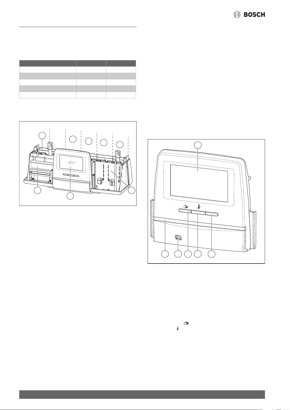
Fig. 1 Overview of slots
[1] Slot A (central module)
[2] Slot B (power supply module)
[3] Slot 1
[4] Slot 2
[5] Slot 3
[6] Slot 4
[7] Slot C
[8] User interface
3.1.1 Notice regarding fitted modules
The additional modules can be installed in any free slot 1...4. In doing so,
make sure that the power supply leads from module to module. We
recommend that you insert the modules in order from left to right to
ensure the heating circuits are logically numbered.
When using the following modules, it is advisable to mount them at
specific slots.
FM-AM
The module only affects the control unit in which it is fitted. If the module
is installed in the master control unit with address 0, it is effective for the
connected boiler(s). If the module is fitted in a substation, it will respond
to the heat requirement issued by that substation.
FM-SI
Due to the length of the SI connecting lead, the safety module should be
mounted at slot 1.
reset
23456
Fig. 2 User interface
[1] Touch screen
[2] Reset button (e.g. high limit safety cut-out, SAFe)
[3] Chimney sweep button (Flue gas test)
[4] Key for manual operation
[5] USB interface for service purposes (behind cover)
[6] LED status display
Function buttons
The function buttons enable
• Manual operation
• Flue gas test
• Reset (e.g. high limit safety cut-out, SAFe)
rese
0010005507-001
6
Control 8313 – 6720859567 (2017/03)
Page 7
Standards, regulations and directives
System status, function status, component status
The status of the system, the functions and system components is
displayed via the Function status display ( Fig. 6, [1], page 12), the
System components status display ( Fig. 6, [15], page 12) and the
LED status display ( Fig. 2, [6]):
• Green = system in automatic mode
• Yellow = system in manual operation, Flue gas test, Service display or
Blocking fault SAFe
• Yellow flashing = Control unit coupling
• Red = Fault
Battery CR2032
The battery ensures that the time and date are not lost when the
control unit is switched off or in the event of a voltage failure
( Fig. 4, [8], page 9).
3.3 Central module ZM5313
The central module controls the following functions:
• Functions of a boiler circuit or a heating circuit with mixer
• Functions of the DHW supply
• BUS communication with the SAFe burner control unit
• Function of the safety chain (SI chain)
• Function of flue gas damper
• Modulating control of boiler circulation pump (possible via 0...10 V)
3.4 NM582 power supply module
The power supply module ( Fig. 1, [2], page 6) supplies voltage to the
following components:
• Control unit
• Load outputs (e.g. pumps, burners, actuators)
• Boiler controller
• Modules used and corresponding connected system components
(e.g. sensor)
It is equipped with:
• 2 safety switches (10 A) as fuse protection of the power sources for
– the central module and user interface
– the modules at slots 1...4
• ON/OFF switch, that switches the phase (L) and neutral conductor (N)
If a safety switch has tripped due to overload, the pin projects noticeably
out of it.
To switch on the safety switch:
▶ Push in the pin.
If the safety switch triggers frequently:
▶ Check the current consumption.
3.5 Base module BM592
A power supply for 24 V components is available at slot C on the base
module.
• Connection: 24 V =, max. 250 mA
▶ Do not exceed the total current.
3.6 FM-MM function module (accessory)
The FM-MM module regulates 2 independent heating circuits with mixer.
The module can be used more than once in the control unit. The
functions of the module are selected and adjusted via the display.
The adjustable functions and parameters are described in the menu
structure of the control unit ( Chapter 9, page 17).
3.7 FM-MW function module (accessory)
The FM-MW module regulates 1 heating circuit with mixer and 1 DHW
supply system. The module can be used more than once in the control
unit. The functions of the module are selected and adjusted via the
display.
The adjustable functions and parameters are described in the menu
structure of the control unit ( Chapter 9, page 17).
3.8 FM-SI function module (accessory)
The purpose of the FM-SI function module is to integrate external
safety equipment into the system or system control. When integrated
into the system control, faults are evaluated via the control unit
(observe Chapter 5.8, page 10).
Examples of external safety equipment:
• Low water indicator
• Pressure limiter
• Additional high limit safety cut-out (STB)
3.9 FM-RM function module (accessory)
The module allows components (e.g. coupling relay, modem) to be
installed on a mounting rail. It can only be installed at slot C.
The maximum overall height of the components is 60 mm. The maximum
supply voltage is 230 V.
4 Standards, regulations and directives
The following are some of the regulations and standards that must be
observed during installation and operation:
• Regulations for electrical installation and connection to the
electrical grid
• Pressure Equipment Directive – systems with boiler temperatures
> 110 °C
• EN 12953-6 – Shell boilers. Requirements for equipment
for the boiler
• EN 12828 – Heating systems in buildings
• ICOM Water treatment guide for commercial heating systems.
• Country-specific regulations to protect potable water
(e.g. DVGW Code of practice W551– Drinking water protection)
• Manufacturer's technical Codes of Practice (e.g. in the catalogue)
• National standards and regulations
Control 8313 – 6720859567 (2017/03)
7
Page 8
Installation
5 Installation
5.1 Assembly
Descriptions of how the control unit is positioned at the heat source are
provided in the installation instructions for the control unit and
documentation for the heat source.
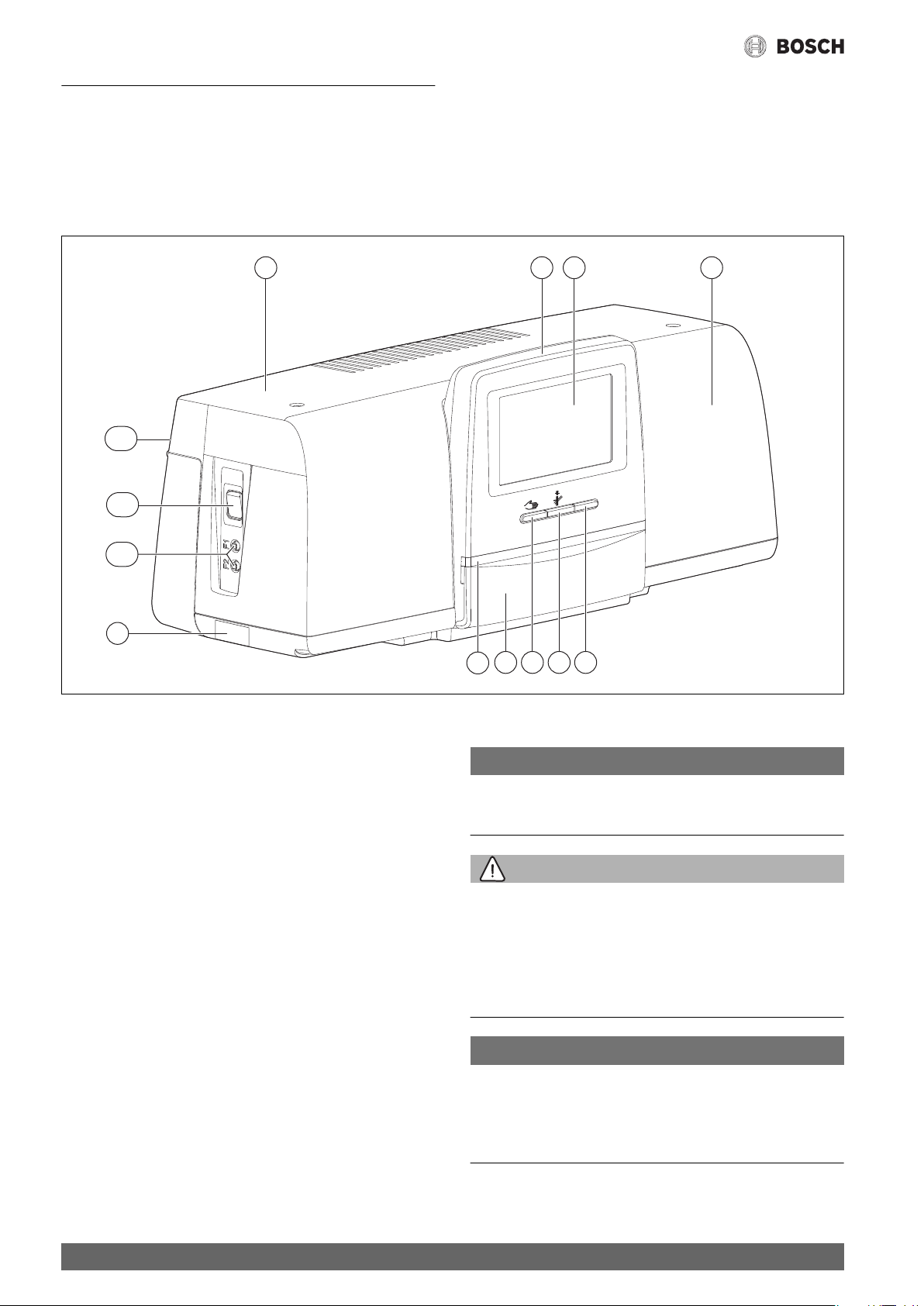
5.2 Overview of controller
1 2 3 1
12
11
10
9
Fig. 3 Overview of controller
[1] Housing lid/cover
[2] User interface
[3] Touch screen
[4] Reset button (e.g. high limit safety cut-out, SAFe)
[5] Chimney sweep button (Flue gas test)
[6] Key for manual operation
[7] Cover (USB interface for service purposes, behind cover)
[8] LED status display
[9] Type plate
[10] F1-, F2 circuit breaker
[11] ON/OFF switch
[12] Back panel
reset
47
8
56
0010003622-001
5.3 Electrical connection
NOTICE:
Faults/material damage due to inductive interference!
▶ Make sure all low-voltage cables are routed separately to mains
voltage cables (min. clearance 100 mm).
WARNING:
Risk to life and of system damage due to high temperatures.
All parts directly or indirectly exposed to high temperatures must be
designed to withstand these temperatures.
▶ Keep cables and electrical wiring at a safe distance from hot
components.
▶ Route cables and electrical wiring in the cable routings provided,
or above the insulation.
NOTICE:
Material damage as a result of disregarding other instructions!
If other instructions for components are disregarded, the heating system
may develop faults or be damaged due to incorrect connections/settings.
▶ Follow the directions in all instructions for the components that are to
be installed.
8
Control 8313 – 6720859567 (2017/03)
Page 9
Installation
Note the following when making electrical connections:
• All electrical connections, safety measures and safety devices must
be implemented by an approved contractor, taking into account the
standards and guidelines that are applicable in each case as well as
the local regulations.
• Establish electrical connection as a fixed connection in accordance
with local/national regulations.
• Electrical connections are established as specified in the connection
diagram for the control unit and the module.
To prevent inductive influences:
▶ Make sure all low-voltage cables are routed separately to mains
voltage cables (min. clearance 100 mm).
• When installing the devices, ensure an earth connection is present.
• Do not exceed the total current stated on the data plate, and the
partial currents for each safety switch and connection.
• Before opening the control unit, disconnect all poles of the control
unit and secure against unintentional reconnection.
• Incorrect attempts to make connections under voltage may damage
the control unit beyond repair and lead to dangerous electric shocks.
▶ Establish electrical connections as specified in the connection
diagram of the control unit and the local conditions.
5.4 User interface connections (HMI)
5.5 Connecting the heat source to the control unit
5.5.1 Connection to the SAFe
WARNING:
Danger to life due to flue gas at the installation location!
With older SAFe software versions (not permitted here), the heat source
may start automatically in unfavourable circumstances!
Unfavourable scenario: connection between heat source (with old SAFe)
and ZM5313 is interrupted.
▶ Only use heat sources with SAFe with software version ≥ Table 3.
If a boiler with SAFe burner control unit is being connected, the EMS
connection has no function!
SAFe heat sources are heat sources that are equipped with a SAFe
(burner control unit) for burner control. The SAFe is directly connected
to the higher level plant control system (e.g. Control CC 8313).
As the software version of the connected heat source determines
whether or not the control functions correctly, the software version of
the SAFe must be checked directly following connection.
Connections:
• On the ZM5313 central module at the BUS SAFe and mains
SAFe terminals
• On the SAFe at the BUS and mains SAFe terminals.
1
11
10
9
8
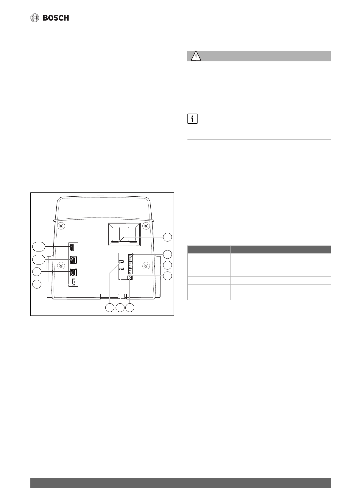
Fig. 4 User interface connections
[1] Slide type insert for SD card
[2] CAN-BUS connection (no function, provided for
subsequent functions)
[3] Modbus-RTU connection for Bosch/Bosch CHP module
[4] EMS connection (connection for EMS heat source with its own
basic control (control panel))
[5] Address setting of control unit
[6] Jumper (J2) for activating the Modbus-RTU terminating resistance
[7] Jumper (J1) for activating the terminating resistance CAN-BUS
[8] Battery CR2032
[9] Network connection 2 (CBC-BUS)
[10] Network connection 1 (Internet, Modbus TCP/IP, CBC-BUS)
[11] USB connection
Depending on the use and configuration, the plug-in connections on the
rear of the user interface must be occupied.
Configuration of CAN-BUS/Modbus-RTU/EMS plug:
• Jumper for activating the Modbus-RTU terminating resistance
• Jumper for activating the CAN-BUS terminating resistance
LAN1
LAN2
USB1
+-
J1
3 2 13 2 1
J2
2 1
2
3
4
567
0010005508-001
Check SAFe version
▶ Check at the heat source whether the SAFe has at least one of the
software versions listed in table 3.
SAFe Software version
10 V4.27
20 V4.23
30 V4.27
40 V4.23
42 V4.28
50 –
1) No function with SAFe 50
1)
Table 3 SAFe version
Control 8313 – 6720859567 (2017/03)
9
Page 10

Installation
5.5.2 Connection to a EMS heat source
NOTICE:
Material damage due to incorrect connection!
When connecting EMS heat sources:
▶ Remove jumper at the external interlock terminal.
▶ Only connect safety equipment directly at the EMS boiler.
EMS heat sources have their own basic control (control panel,
e.g. BC10). The SAFe is connected to the control of the heat source.
If a plant control system is installed, it is superordinate to the control of
the heat source.
The user interface of the control unit and the basic control
(control panel) of the heat source are directly connected.
Connections:
• On the back of the user interface at the EMS terminals
( Fig. 4, [4], page 9) with
• Basic control of the heat source at the (EMS)-BUS terminals
When connecting a boiler via the EMS terminals:
▶ Remove jumper at the external interlock terminal.
The external interlock connection has no function in conjunction
with EMS boilers!
▶ External safety equipment that lead to blocking must be connected
to the EMS boiler directly.
5.5.3 Connection via the Modbus interface
For heat sources (e.g. CHP module) that are connected via the
Modbus-RTU ( Fig. 4, [3], page 9):
▶ Connect communications cable to the Modbus-RTU connection.
▶ Consider connection to the heat source.
5.8 Connection of safety equipment and the FM-SI
module
SAFe heat source
If a boiler with SAFe burner control unit is being connected, the EMS
connection has no function!
▶ Connect safety equipment or a condensates neutraliser at the FM-SI
module.
▶ Close unused SI inputs with a jumper.
When using a condensate neutraliser:
▶ Connect condensate neutraliser to SI1 input.
EMS heat source
Use of the FM-SI with EMS heat sources is not permitted if the heat
source is connected via the EMS terminal ( Fig. 4, [4], page 9).
▶ Connect external safety equipment directly to the control of the heat
source (terminal SI 17, 18).
▶ Always connect safety equipment that shuts down the heat source to
the basic control of the heat source (EMS control).
If EMS heat source was selected in the setting:
▶ Open the safety chain (terminal SI 17, 18) at the ZM5313
without fail.
▶ Do not install a jumper!
If safety equipment is connected, a jumper is installed or a Sl module is
inserted at the ZM5313, a fault display is generated.
To avoid vagabond voltages:
▶ Only connect cable shield to one control unit!
5.6 Connection to other control units in the 8000 series
or to a network
The connection options are presented in Chapter 16.1, page 37.
5.7 Connection of modules
Mains voltage
The 230 V power supply must be ensured for modules fitted at slots
1…4 via a plug-in connector on the power supply module. The modules
supply voltage to one another via additional plug-in connections.
If voltage is not supplied to the module or its 230 V components
(e.g. because the plug-in connector has not been inserted), the
components assigned to this module are not switched on (e.g. pumps).
This malfunction cannot be detected at the user interface itself as the
display and control functions are independent of the 230 V voltage.
5.9 Remote control
If a remote control is provided for the heating circuit, this must be
connected to the BF terminals. The remote control is assigned to the
corresponding heating circuit via the coding switch in the remote
control.
5.10 Other connections
Other connections may need to be established, depending on the
function of the modules.
▶ Observe documents and connection diagrams of the installed
modules!
UM10 function module
A UM10 must not be installed in a heating system if the heat source is
activated via the ZM5313. The ZM5313 takes over the UM10
functionality.
10
Control 8313 – 6720859567 (2017/03)
Page 11
6 Operation of the control unit
6.1 Control elements of the control unit and the user interface
Operation of the control unit
1
10
9
8
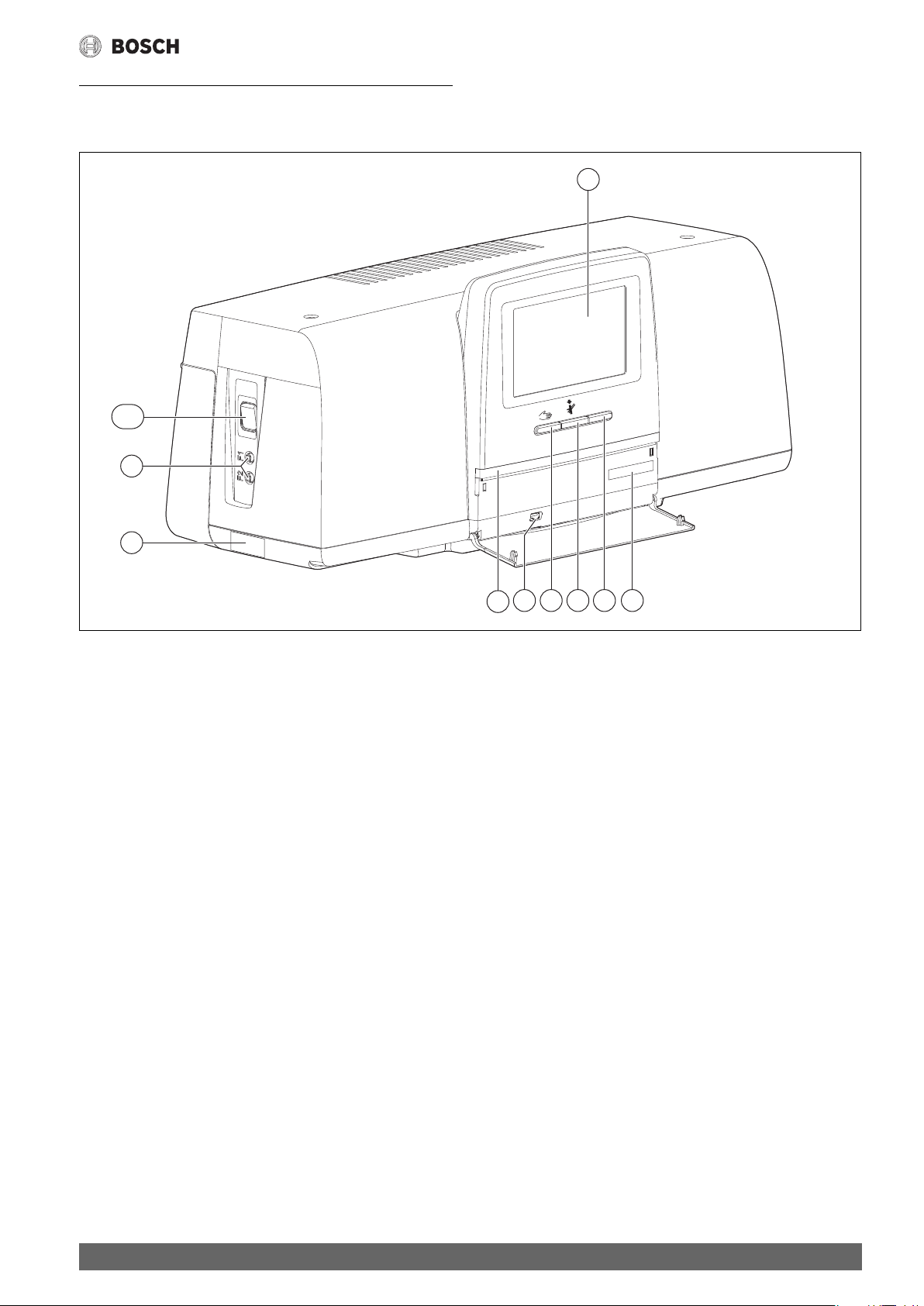
Fig. 5 Control elements
[1] Touch screen
[2] Activation code (registration code)
[3] Reset button (e.g. high limit safety cut-out, SAFe)
[4] Chimney sweep button (for Flue gas test)
[5] Manual operation key
[6] USB connection (e.g. for service purposes)
[7] LED status display
[8] Data plate
[9] F1-, F2 circuit breaker
[10] ON/OFF switch
reset
7
3 26 45
0010005509-001
Control 8313 – 6720859567 (2017/03)
11
Page 12
Operation of the control unit
t
6.2 Function buttons and system status
Function buttons
The function buttons enable
• Manual operation
• Flue gas test
• Reset (e.g. high limit safety cut-out, SAFe)
System status, function status, component status
The status of the system, the functions and system components is
displayed via the Function status display ( Fig. 6, [1], page 12), the
System components status display ( Fig. 6, [15], page 12) and the
LED status display ( Fig. 5, [7]):
• Green = system in automatic mode
• Yellow = system in manual mode, Flue gas test, Service display or
Blocking fault SAFe
• Yellow flashing = Control unit coupling
• Red = Fault
rese
1 2 3 4 5 6
6.3 Operating and display elements of the touch screen
Whether menu items can be displayed or selected depends on which
modules are inserted and which settings have been made.
The displays shown are examples. The display of the symbols depends
which software is installed, which modules are inserted and which
settings have been made.
The operating instructions contain information on operation of the
control unit.
▶ Observe operating instructions of the control unit and the heat
source.
The following displays can be called up via the touch screen:
• Heat source in the system
• Heat consumers and heat distributors in the system
• Monitor data
• Setting parameters for commissioning and system optimisation.
These parameters are protected by a code.
15
50 °C
on/o
14
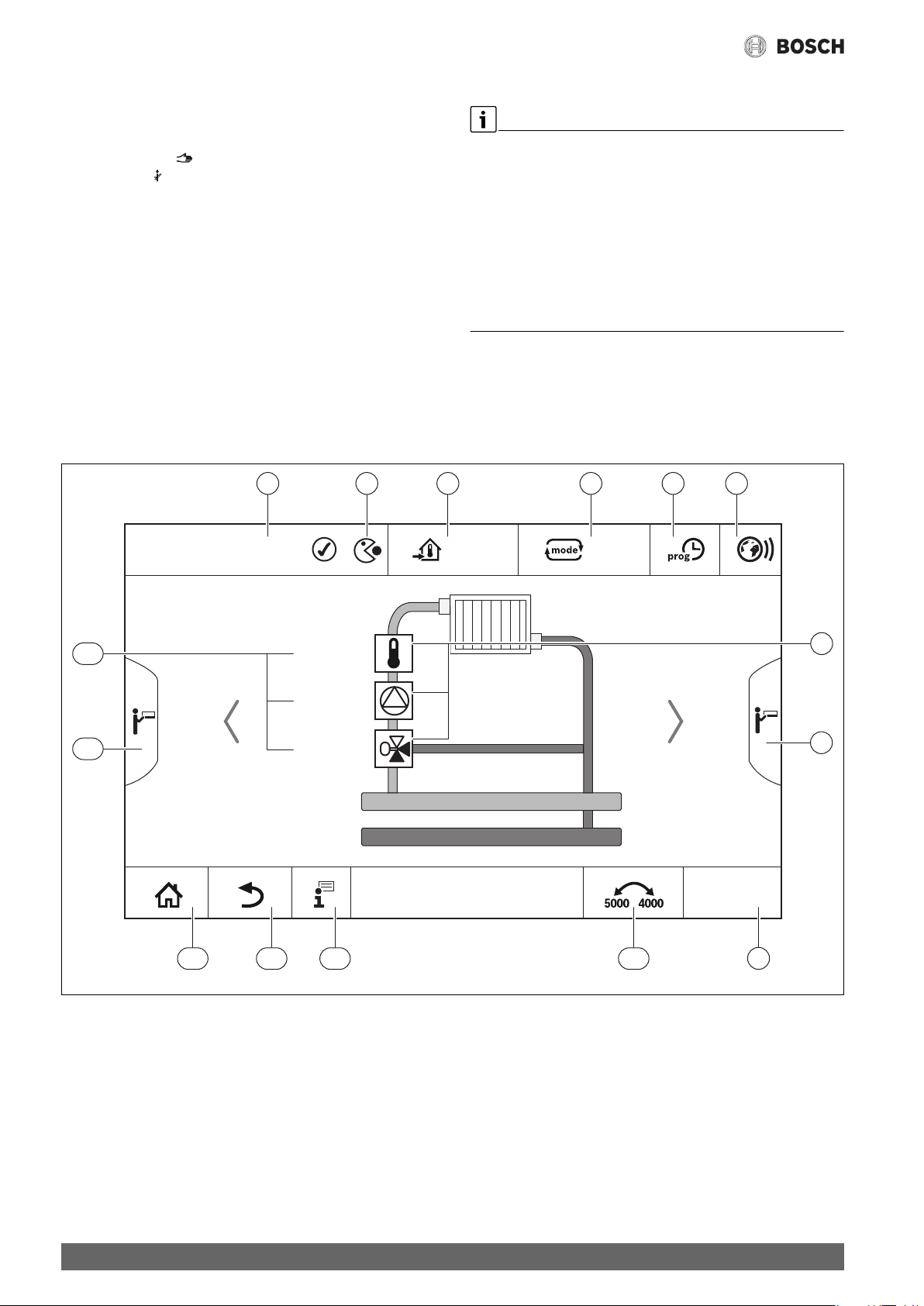
Fig. 6 Operating and display elements
[1] Display of system, subsystem or function
[2] Status display of active menu level
[3] Display of temperature set (set temperature)
[4] Display of operating mode set
[5] Display of time program set
[6] Display of Internet connection
[7] Display of system components
[8] Advanced functions for heating circuit, DHW
[9] Display of time
[10] Press field to switch between display types on the display
[11] Information menu
30 %
12:00
10111213
[12] Press field to go back to the previous level/screen
[13] Press field to return to the system overview
[14] Advanced functions of the heat source
[15] Status display of system components
The symbols used are listed in Chapter 23.3 on page 51,
accompanied by an explanation.
9
0010005510-001
7
8
12
Control 8313 – 6720859567 (2017/03)
Page 13
Operation of the control unit
6.4 Operating the appliance
The operating instructions contain information on operation of the
control unit.
▶ Observe the operating instructions of the control unit.
A description of operation of the control unit from the contractor's
standpoint is provided below.
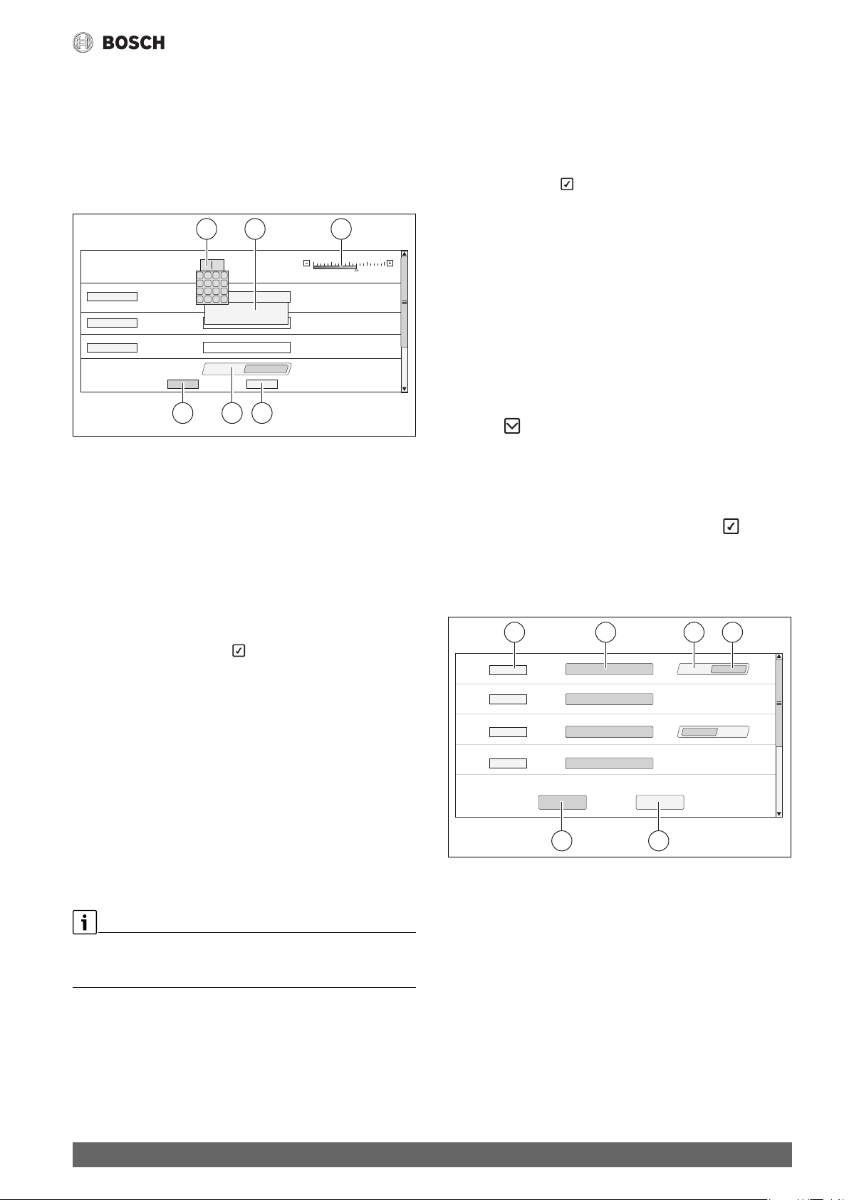
6.5 Modifying settings
1 2 3
°C
C
7
9
8
+
4
6
5
1
3
2
-
.
OK
x
0
O On
6 45
Fig. 7 Modifying settings
[1] Numerical values
[2] Selection box
[3] Scale
[4] Cancel
[5] Off/On
[6] Save
Changes to parameters can be made in a number of different ways,
depending on the menu item.
• Changing numerical value
Numerical values can be changed by entering the number directly.
A keyboard opens when you tap the numerical field.
▶ Type in numerical values and .
If the values you entered are invalid, the previous value will be
displayed.
• Scale
You can change the value by tapping the Plus and Minus keys.
• Selection box
Tap this field to open a selection box. Tap on the required parameter/
function to select it.
• Label text field ( Chapter 6.6, page 13)
• Off/On
Tap on the required parameter/function to select it.
To save the changes:
▶ Tap Save field.
To cancel the operation:
▶ Tap Cancel field.
If parameters are linked to settings, a temperature, for example, can only
be selected/modified if the function is set to On.
Fields that are not active are highlighted in grey.
-30 -22 -15 -7 0
0010007715-001
6.6 Labelling a text field
In some cases, the selection box contains an empty field/User-defined
which can be labelled by entering text.
▶ Tap on the empty field.
A keyboard opens.
▶ Enter a suitable text for the length of the field.
▶ Confirm entry with
To save the changes:
▶ Tap Save field.
To cancel the operation:
▶ Tap Cancel field.
6.7 Labelling the text field of the FM-SI module
(accessory)
You can name the inputs of the FM-SI safety module according to the
connected safety equipment.
If other devices are connected, you can assign your own names to these
by entering text in an empty field. If fields have been selected but not
saved, the selection is reset.
To label a field:
▶ Tap the field.
The pre-selection opens.
▶ Select name.
-or-
▶ Tap FM-SI field.
A keyboard opens.
▶ Enter a suitable text for the length of the field and tap to apply.
To save the change:
▶ Tap Save field.
To cancel the operation:
▶ Tap Cancel field.
31 2 4
6 5
Fig. 8 Labelling a text field
[1] FM-SI1
[2] Name of safety equipment
[3] Free
[4] Allocated
[5] Cancel
[6] Save
0010009240-001
Control 8313 – 6720859567 (2017/03)
13
Page 14

Function keys of the user interface
t
t
6.8 Calling up the service menu
The Service menu is protected against unauthorised use. The Service
menu is intended exclusively for approved heating contractors.
Unauthorised access will invalidate the warranty!
The Service menu can only be accessed from the system overview.
To call up the Service menu:
▶ Tap and hold for roughly 5 seconds.
12:00
1
Fig. 9 Call up Service menu
[1] Fault history, Service display
In the Service menu tap the symbol to select the Settings or the
symbol to select the Monitor data.
0010009028-001
1
7 Function keys of the user interface
reset
1234
Fig. 11 Function buttons
[1] Reset button
[2] Chimney sweep button
[3] Manual operation key
[4] LED status display
7.1 Reset key
When the key is pressed the locking fault is unlocked and the
functions are reset (e.g. following triggering of the high limit safety cutout or resetting of the SAFe).
To unlock a function:
▶ Key Hold down for 2 seconds.
rese
rese
0010007084-001
2
Fig. 10 Service menu
[1] Symbols for available functions
[2] Monitor data
12:00
0010008706-001
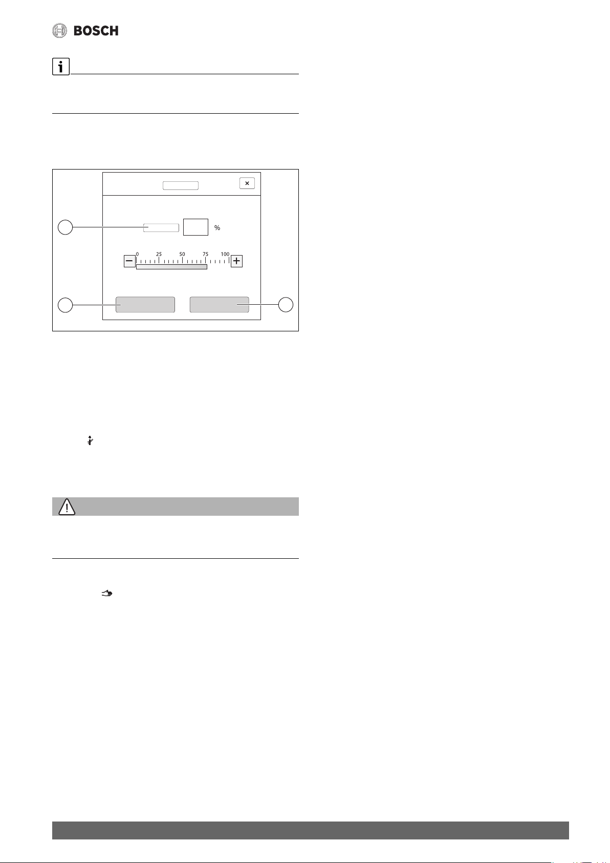
7.2 Chimney sweep button (flue gas test)
WARNING:
Risk of scalding from hot water!
Setting the set temperature > 60 °C creates a risk of scalding.
▶ Do not draw off DHW unmixed.
To perform the flue gas test:
▶ Observe the relevant national requirements for limiting flue losses
from the heating system.
The flue gas test is switched on if required at the heat source
( Technical documentation of heat source) or at the control unit.
▶ Ensure heat consumption within the heating system.
▶ Starting from the initial position, hold the key down for several
seconds.
The flue gas test starts immediately.
The parameters for defining the conditions under which the flue gas
test is carried out are shown in the display.
▶ Setting parameters (e.g. modulation).
▶ Tap Save.
The heat source is operated at the set output.
14
Control 8313 – 6720859567 (2017/03)
Page 15
If a preset parameter (e.g. minimum boiler output) is exceeded or
undercut when making the adjustment, a warning message appears that
must be confirmed. The parameter remains at the previous value.
To exit the view:
▶ Tap Cancel.
The flue gas test continues.
3
77
Function keys of the user interface
Emergency operation
The “emergency operation” operating mode is activated automatically if
the user interface is faulty or if communication with the control unit via
the internal BUS is interrupted.
In the “emergency operation” operating mode, the heat source heats
continuously without setback at a boiler temperature of 60 °C. All pumps
connected to the central module (boiler circulation pump, pump of
heating circuit 00, DHW pump and DHW circulation pump) are switched
on.
The SR mixing valve is de-energised and must be adjusted manually if
necessary. The installed function modules cannot be triggered by the
BCT531 user interface and do not work.
The LED status display lights up red in the “emergency operation
”operating mode.
2
Fig. 12 Flue gas test
[1] Save
[2] Cancel
[3] Modulation
The LED status display ( Fig. 11, [4], page 14) lights up yellow during
the flue gas test and is accompanied by a constantly recurring pop-up
window.
To conclude the flue gas test:
▶ Press key again.
If the flue gas test is not ended manually, it ends automatically after
30 minutes.
1
0010009474-001
7.3 Key for manual operation, emergency operation
WARNING:
Risk of scalding from hot water!
Setting the set temperature > 60 °C creates a risk of scalding.
▶ Do not draw off DHW unmixed.
Key for manual operation
Press the key to ensure the “Manual operation” operating mode is
available if e.g. the user interface has failed or the internal control unit
communication has been disrupted. The heat source heats continuously
without setback at a boiler temperature of 60 °C. The pumps and mixers
of the heating circuits, the DHW heating of the central module and the
function modules continue running normally. The LED status display
lights up yellow.
Manual operation
The “manual operation” operating mode can be set and adjusted for
every function separately.
▶ Observe the operating instructions of the control unit.
Control 8313 – 6720859567 (2017/03)
15
Page 16
Commissioning
8 Commissioning
8.1 Notes on commissioning
▶ Ensure there is sufficient heat load available
(e.g. by the DHW heating).
Otherwise the heat source will switch off.
Different messages are displayed according to the application.
8.2 Control unit settings
With this control unit, a number of temperatures are specified by the
SAFe of the heat source.
The temperature values are set or modified via the touch screen.
Long burner run times can be ensured by optimising the settings at the
control. Rapid temperature fluctuations in the heat source are avoided.
Gentle temperature transitions extend the service life of the heating
system.
8.2.1 Setting the control unit address
Each connected control unit must be given a different address if several
control units are networked. A fault is indicated on the display of the user
interface if the same address is allocated more than once.
The address is set [5] at the control unit on the back of the user
interface.
▶ Remove the user interface.
▶ Set the control unit address (e.g. using a screwdriver).
Address Description
0 Stand-alone control unit (default setting):
• The controller operates alone.
Master (lead control unit):
• The master activates the heat source.
• Always connect the outside temperature sensor to the
master.
• The master recognises if an address has been allocated
more than once. A fault is indicated on the display of the
user interface.
• All networked controllers transfer their set values to the
master. The master uses them to generate the overall set
value.
• Only 1 master is permitted in each network!
1...15 Slave (control units subordinate to the master):
• The address 0 must never be assigned to a slave.
• Each address is only allocated once.
Table 4 Control unit addresses
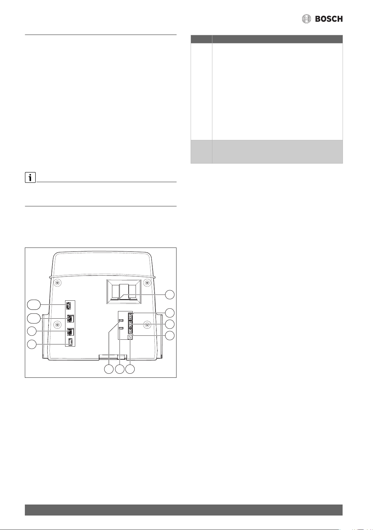
8.2.2 Terminating resistors
The terminating resistors J1 and J2 ( Fig. 13, [6], [7], page 16) are
closed in the delivered condition (activated = inserted). If a network is
established via the BUS connections ( Fig. 13, [2], [3], page 16), the
jumpers must be opened here and closed at the last BUS node.
11
10
9
8
LAN1
LAN2
USB1
+-
J1
3 2 13 2 1
J2
2 1
567
0010005508-001
Fig. 13 Back of the user interface
[1] Slide type insert for SD card
[2] CAN-BUS connection
(no function, provided for subsequent functions)
[3] Modbus-RTU connection for CHP module
[4] EMS connection (connection for EMS heat source
with its own basic control (control panel))
[5] Address setting of control unit
[6] Jumper for activating the Modbus-RTU terminating resistance
[7] Jumper for activating the CAN-BUS terminating resistance
[8] Battery CR2032
[9] Network connection 2 (CBC-BUS)
[10] Network connection 1 (Internet, Modbus TCP/IP, CBC-BUS)
[11] USB connection
1
2
3
4
16
Control 8313 – 6720859567 (2017/03)
Page 17
Menu structure
Chapter 6 from page 11 describes how to operate and call the menus
9 Menu structure
The control unit electronics have 2 levels, in which system-dependent
settings are made. The levels and parameters displayed depend on the
installed modules and the factory defaults. The parameters that are not
required for the selected function are not displayed.
Parameters that are not active are highlighted in grey.
The functions of the most frequently used modules FM-MM, FM-MW and
FM-SI are described in these instructions, in addition to the basic
functions of the control unit.
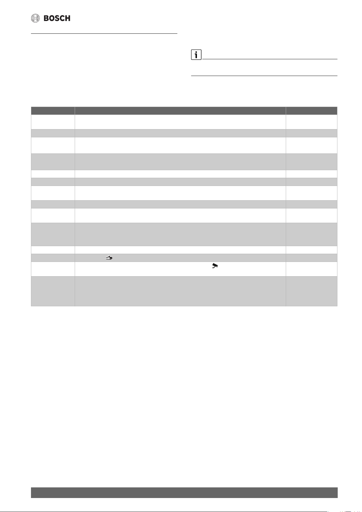
Main menu Explanation/Function Further information
General
characteristic data
Module selection For selecting whether modules are detected and installed automatically or manually chapter 9.2, page 18
Boiler
characteristics
Heating circuit data Setting of different heating circuit data (e.g. heating circuit system, maximum flow temperature)
Domestic hot water Water treatment settings chapter 18, page 27
Reset Reset values in the main menu and service menu to the default settings. chapter 14, page 37
Version Shows the software versions of the user interface, the control unit and the Open Source information Chapter 2.2, page 5,
Control unit Save or load configurations chapter 20.1, page 44
Connectivity Activation and setting of network connection Chapter 9.6, page 28
Function test Check whether system components (e.g. pumps) are correctly connected.
Lock screen Option for locking the screen. chapter 9.7, page 29
Manual operation When the key is pressed, the heat source operates using stored values. chapter 7.3, page 15
Monitor data Shows set values and actual values of the system. Tap the symbol to display the values in the
Fault Shows the faults in the heating system. The user interface can only display the faults for the
Table 5 Main menu
Settings of the control unit, of heating system parameters and the house properties chapter 9.1, page 18
Setting of different boiler data, depending on heat source
If a FM-SI is installed: settings for the safety equipment.
and display of current heating curves of the relevant heating circuit
The displays depend on which modules are installed. Depending on the operating conditions, there may
be a time delay between the demand and display.
bottom bar.
control unit it is connected to.
with the user interface.
In the following tables, the default settings are highlighted in bold in the
"Settings/Adjustment range" column.
chapter 9.3.1, page 19
chapter 9.4.1, page 21
chapter 9.5, page 27
chapter 15, page 37
Chapter 9.6, page 28
chapter 17, page 43
chapter 19, page 44
chapter 11.3, page 32
Chapter 20.5, page 45
and chapter 20.6,
page 45
Control 8313 – 6720859567 (2017/03)
17
Page 18

Menu structure
9.1 General characteristic data
Submenu Settings/
adjustment
range
Language Selection of language of texts displayed.
Date format Selection of date format
Calendar Entry of date
Time Entry of time
Time Zone Europe/Berlin Regional zone where the same time applies
Europe/London
Europe/Paris
Europe/Moscow
Universal time/
Greenwich Mean
Time
Minimum outdoor
temperature
Building Light Poor heat storage capability, e.g. pre-fabricated
Insulation standard Small No or minimum insulation effect, e.g. house
Outside temperature source ZM The outside temperature sensor is connected to
External heat demand None
Table 6 General characteristic data menu
–30...–10...0 °C The minimum outside temperature is the average
Medium medium heat storage capability,
Heavy High thermal storage capacity,
Medium Medium insulating effect, e.g. house with 10 cm
Good Large insulating effect, e.g. new build or
Control unit 00 The outside temperature sensor is connected to a
Off/On WA1/3 closed = external heat demand on
Temperature Specifies the effect the 0...10 V input (WA1/2) is
Output Specifies the effect the 0...10 V input (WA1/2) is
Explanation Note
▶ For regional average minimum outside
of coldest outside temperature recorded in each
previous year.
▶ Adapt heating system to the construction
houses, wooden-framed constructions
e.g. house built with hollow blocks
e.g. house made of bricks
▶ Adapt heating system to the insulation
without insulation
mineral wool
renovated house with 20 cm mineral wool
The parameter is only displayed with control
this control unit.
different control unit. The sensor values are
transmitted via the BUS.
to have on the system.
to have on the system.
units with address > 0 (e.g. substations).
Chapter 10.3.1, page 31
Chapter 10.3.2, page 31
temperature values, refer to tab. 23
( Chapter 10.1, page 30).
( Chapter 10.2.1, page 30).
situation ( Chapter 10.2.2, page 30).
9.2 Module selection
When the control unit is switched on or after a reset, the modules are
automatically recognised and their information downloaded.
If the modules are not recognised automatically:
▶ Set the modules manually.
Submenu Settings/adjustment range Explanation Note
Slot A ZM5313 Automatic recognition and
installation of the modules for slot A
Slot 1...4 None Slots for function modules and
Module selection The installed modules can be
selected from a list.
Table 7 Module selection menu
18
Slot for boiler module
auxiliary modules
Control 8313 – 6720859567 (2017/03)
Page 19

9.3 Boiler parameters
9.3.1 Basic boiler settings
Depending on which boiler type and burner type have been chosen,
special setting options will be displayed.
Menu structure
Submenu Settings/adjustment
Explanation Note
range
Boiler type None No boiler available. Control is used as standalone
master control unit with address 0 or as
substation.
SAFe The parameters of the SAFe are adopted by the
heat source. A boiler control is not installed in the
heat source.
EMS The parameters of the boiler control the SAFe are
adopted by the heat source in the control unit.
Hydraulic Boiler The heating circuit on the central module is used
as boiler circuit.
Heating circuit The heating circuit on the central module is used
as boiler circuit (00).
Sensor Heat source
(low loss header)
Heating circuit (Flow)
Boiler circulation pump No/Yes Setting that specifies whether a boiler circulation
pump is installed.
Modulating pump No/Yes Setting that specifies the conditions according to
which the pump is controlled
Pump control mode In accordance with
boiler operating
conditions
Off/On Setting that determines whether the modulating
pump is to be switched on and off via a 0....10 V
signal.
According to output ▶ Observe pump manufacturer's
Temperature difference
between boiler and low
loss header
Pump overrun time for
lead boiler
According to
temperature difference
1...4...10 K Setting of the temperature differential between
0...60...120 Min To utilise the heat stored in the heat source to the
Setting that specifies the conditions according to
which the pump is controlled
temperature sensor in the system flow (FZ) and
boiler water temperature sensor.
maximum possible extent, a time must be
specified for which the pump should continue to
operate after the burner has been shut down.
Pump overrun time for
slave boiler
0...60...120 min To utilise the heat stored in the heat source to the
maximum possible extent, a time must be
specified for which the pump should continue to
operate after the burner has been shut down.
Voltage for min. flow
temp
Voltage for max. flow
temp
Boiler temperature
increase at low loss
header
0...10 V Specifies the voltage at which the minimum flow
rate occurs.
0...10 V Specifies the voltage at which the maximum flow
rate occurs.
No/Yes 5 K is added to the desired set value for the boiler
temperature, so that the set value can be reached
quickly and safely.
Standalone as master control unit with address
0. Substation as control unit with address >0
Note selection at menu item Hydraulic.
( Chapter 5, page 8 and chapter 11.2,
page 32)
Note selection at menu item Sensor.
Attention: the SI and external interlock terminal
must be opened!
( Chapter 5, page 8 and chapter 11.2,
page 32)
Boiler/heating circuit 00 with the terminals PK,
SR, FZ ( Chapter 9.4, page 21)
Chapter 11.1.1, page 32
The control operates within the limits specified
by the SAFe, e.g. maximum boiler temperature.
Digital activation of modulating pump.
Activation: On = 10 V, Off = 0 V
Prerequisite: continuous external power supply
to pump.
specifications.
Change the factory setting only in exceptional
cases.
Change the factory setting only in exceptional
cases.
Observe pump manufacturer's specifications.
Observe pump manufacturer's specifications.
Control 8313 – 6720859567 (2017/03)
19
Page 20

Menu structure
Submenu Settings/adjustment
Explanation Note
range
External Heat Detection No/Yes Once sufficient heat to supply the system has
built up at sensor FZ, the heat source is
The temperature sensor FZ is in the low loss
header or buffer cylinder.
prevented from starting. If the system set value is
undercut by 4 K, the heat source is started.
Maximum shutdown
temperature
30...85...99 °C The burner is switched off once the heating flow
temperature reaches the maximum cut-off
temperature at the latest.
The maximum possible cut-off temperature is
specified by the SAFe of the connected heat
source.
Change the factory setting only in exceptional
cases. The value can only be reduced.
Chapter 11.2, page 32
Maximum boiler output 0...100 % Limiting the performance of the heat source This function is active in heating and DHW
mode.
Cycle deactivation 0...10...60 min Setting the blocking time between switching off
the heat source and switching it back on
This function is active in heating and DHW
mode.
Negative hysteresis -30...-4...0 K Setting that specifies when the set value is
undercut what the difference in temperature
should be before heat production starts
Positive hysteresis 0...2...15 K Setting that specifies when the set value is
exceeded what the difference in temperature
should be before heat production ends
Max. Air Correction -9...0...9 Matching the fan speed The function depends on the heat source.
Min. Air Correction -9...0...9 Matching the fan speed The function depends on the heat source.
Service display None
After hours Maintenance according to hours run
(only in control units with direct activation of
heat source)
Next maintenance Setting the number of hours until maintenance is
next due
Burner run time since
last maintenance
Number of hours that have elapsed since
maintenance was last carried out.
• The service display is recorded in the fault
history can be displayed via the building
services management system.
• The status of the service display can be
requested in the fault history.
• The service display can be reset in the Reset
menu.
Date Service display set according to date: entry of
next maintenance deadline
Table 8 Boiler characteristics menu
9.3.2 Settings of the safety equipment
Submenu Settings/adjustment
Explanation Note
range
FM-SI1...FM-SI5 Free/Allocated Inputs for fault displays Only if a FM-SI is installed. Inputs must be
activated ( Chapter 6.7, page 13 and
chapter 11.3, page 32).
Max. pressure 1 Selection of a name for the connected safety
Max. pressure 2
equipment or entry of an individual name
Min-PressWMS
Neutralisation
STB 2 safe.
Max-pressure1/2 = maximum pressure
limiter 1 or 2
This must be connected to input SI1 when using
a condensate neutraliser.
Unallocated inputs of the safety chain module
must be jumpered.
Min-pr.WMS = minimum pressure limiter
or low water indicator
STB2 Safety = 2nd safety temperature limiter
Table 9 Safety equipment settings
20
Control 8313 – 6720859567 (2017/03)
Page 21

Menu structure
9.4 Heating circuit data
The heating circuit on the central module (PK, SR, FZ) can be used either
as a heating circuit with mixer or as a boiler circuit. If a system
component is used in a function, the other system components can no
longer be used for the other function.
Example: if SR is used as the mixing valve for the boiler circuit, PK cannot
be used for a heating circuit without mixer.
When used as a heating circuit, this is displayed as heating circuit 00.
Display of heating circuits
The designation assigned to the heating circuits depends on the slot of
the heating circuit module. The heating circuits are numbered according
to the sequence of slots. This means that the heating circuits at slot 1 are
displayed as heating circuit 01 and 02. The heating circuits at slot 2 are
displayed as 03 and 04. If a different module is inserted at a slot, these
heating circuit numbers are omitted.
If a name has been assigned to the heating circuit, this is displayed.
Only the heating circuits that are available via modules are displayed.
The heating circuit symbols turn grey if heating circuits are available but
not active. If heating circuits are available and active, the heating circuit
symbols are displayed normally in white.
9.4.1 Basic setting
Submenu Settings/
Explanation Note
adjustment range
Heating circuit Off/On
Heating circuit name Heating circuit
name
You can choose the name of the heating circuit
from a list or give it your own name.
• Basement
• Apartment
• Swimming pool
• Building
• Underfloor
Heating
• Floor
Heating system Radiator/
Underfloor
The type of heating system determines the
gradient or curvature of the heating curve.
Heating
Constant
Base Point
Room
Damping influence of outdoor
temperature
0...100 % Setting that determines the extent to which the
adjusted outside temperature affects the
control parameter.
Remote Control No/Yes Determines whether a remote control is
installed for the heating circuit that influences
the heating circuit.
Underfloor Heating Off/On
Maximum underfloor flow
temperature
20...45...60 °C This value specifies the temperature above
which the flow temperature must not rise.
Maximum flow temperature 30...75...120 °C This value specifies the temperature above
which the flow temperature must not rise.
Minimum flow temperature 5...70 °C Limiting the heating curve to a minimum set
value
This value sets the temperature below which
the flow temperature must not drop.
Actuator No/Yes Information as to whether or not the system is
equipped with a heating circuit mixing valve
Chapter, 12, page 33
Chapter, 12, page 33
Chapter 12.1.1, page 33
The value set influences the heating curve.
The maximum flow temperature depends on the
heat source and is therefore limited by the heat
source.
This parameter cannot be adjusted with the
Constant heating system.
▶ Only change value if necessary.
If the heating circuit is equipped with a heating
circuit mixing valve, this is activated by the
control unit.
The heating circuit is regulated via the flow
temperature of the heat source if no heating
circuit mixing valve is installed. No heating circuit
mixing valve is entered for heating circuit 00.
Control 8313 – 6720859567 (2017/03)
21
Page 22

Menu structure
Submenu Settings/
Explanation Note
adjustment range
Actuator runtime 5...120...600 s Setting the runtime of the available mixing
valves
Generally, servomotors have a runtime of
120 s.
Boiler temperature increase 0...5...20 K The flow temperature for the heating circuit is
obtained by adding the increase in boiler
temperature to the calculated/required flow
temperature.
DHW priority No/Yes The pumps of all heating circuits are switched
off during the water heating phase.
Pump blocking protection Off/On Setting that determines whether or not a pump/
mixer is to be regularly switched on for short
periods to prevent it from seizing up during
extended downtimes.
Overrun time 0...2...60 min Setting that determines how many minutes a
pump should remain switched on once the
switch-on condition no longer exists.
Third party WF control
settings
None Switching the operating mode of the heating
Heating mode/
Setback mode
circuit via an external contact (connecting
terminal WF) at the FM-MM and FM-MW module
WF1/2
Heating mode/
Setback mode/
Automatic
WF1/2/3
External fault
Display of faults for a pump Not available with the connections of the
display for pump
WF1/2
External fault
display for pump
Display of faults for a pump via 1/2 and external
changeover via 1/3.
WF1/2 and
External fault
display for pump
WF1/2 and
external heating/
setback mode
WF1/3 WF1/3
Table 10 Basic settings of heating circuits
If the mixing valve constantly oscillates, the
control characteristics can be slowed down by
reducing the operating time of the mixing valve.
If a heating circuit is controlled with a mixing
valve, a higher set value should be set for the heat
source than the normal set value for the heating
circuit.
In heating circuits with mixer, the mixing valve is
moved in the “close” direction (colder).
Not available with the connections of the
boiler circuit.
Chapter 12.1.2, page 33
boiler circuit.
22
Control 8313 – 6720859567 (2017/03)
Page 23

Menu structure
9.4.2 Heating curve, operating mode
Individual settings can be made for each operating mode separately in
every heating curve.
Heating curve
The heating curve set refers to the Heating system selected under the
menu item Heating circuit data > Basic setting. The settings can be
made in a table or a graphic representation ( Chapter 12.3, page 35).
The following heating curves can be set:
• Constant
• Base Point
• Radiator/Underfloor Heating
• Room
Operating modes
You can set the following operating modes for each heating curve
separately:
• Automatic heating mode
• Automatic setback mode
• Manual heating mode
• Manual setback mode
• Holiday
Temperature settings for the operating modes of the Constant heating curve in the Automatic heating mode operating mode:
Submenu Settings/
Explanation Note
adjustment range
Set flow temperature 10...75...120 °C Constant:
Controlling of a swimming pool heating system
or pre-controlling of ventilation circuits if the
With the Constant heating system, a remote
control cannot be connected for this heating
circuit.
heating must always provide the same set flow
temperature, independent of the outside
temperature.
Standby mode No/Yes The heating circuit or this function is switched
off.
Heating Limit (Summer from /
Outdoor Setback)
No/Yes Selection that determines whether the heating
circuit or a function is to be switched off once a
The heating circuit is switched off
(summer mode) when the setting is Yes.
The heating circuit is switched off from a set
outside temperature.
set outside temperature has been reached.
-50...17...50 °C The heating circuit is switched off when the set
outside temperature is exceeded and switched
back on when it is undercut.
Manual setback mode Shortcut keys If you tap a shortcut key, the display jumps to
Automatic heating mode
Automatic setback mode
the settings area of the selected operating
mode.
You can make separate settings for each
operating mode. For the settings of the setback
types, refer to Chapter 12.1.2, page 33.
Holiday
Table 11 Settings for the operating modes of the Constant heating curve
Temperature settings for the operating modes of the Base Point heating curve in the Automatic heating mode operating mode:
Submenu Settings/
Explanation Note
adjustment range
Outdoor Temperature 1 -50...20...50 °C Initial temperature of the heating curve.
Outdoor Temperature 2 -50...-10...50 °C
Reference temperature for the design of the
heating curve.
Flow temperature setpoint 1 0...45...80 °C Flow temperature for operation with Outdoor
Temperature 1.
Flow temperature setpoint 2 0...80 °C Flow temperature for operation with Outdoor
Temperature 2.
Room temperature setpoint 5...21...50 °C Setting of the required room temperature:
Room influence /
maintenance
None Limits the influence of the room temperature
According to offset
Maximum / room
maintenance
mode
(room temperature hook-up) on the flow
temperature set value. The value specifies the
highest possible room temperature setback.
This also applies for rooms which are also
supplied by the heating circuit and where no
remote control units are installed.
Room temperature offset –5...0...5 °C Adjustment of the temperature differentials
between the actual and set temperature
This adjustment effects a parallel displacement
of the heating curve.
The set Flow temperature setpoint 1 is not
undercut. This temperature ensures that the
minimum boiler temperature is maintained.
Setting under: Heating curve > Outdoor
temperature
Requirements for the setting:
• A Remote Control is selected.
• Room heating system is not selected.
Ensure that the remote control is not exposed to
heat (e.g. lamps, TV sets or other heat sources).
This setting is only recommended if no remote
control has been installed inside the living space.
Chapter 12.1.3, page 33
Control 8313 – 6720859567 (2017/03)
23
Page 24

Menu structure
Submenu Settings/
Explanation Note
adjustment range
Standby mode No/Yes The heating circuit or this function is
switched off.
Heating Limit (Summer from /
Outdoor Setback)
No/Yes Selection that determines whether the heating
circuit or a function is to be switched off once a
The heating circuit is switched off
(summer mode) when the setting is Yes.
The heating circuit is switched off from a set
outside temperature.
set outside temperature has been reached.
-50...17...50 °C The heating circuit is switched off when the set
outside temperature is exceeded and switched
back on when it is undercut.
Manual setback mode Shortcut keys If you tap a shortcut key, the display jumps to
Automatic heating mode
Automatic setback mode
the settings area of the selected operating
mode.
You can make separate settings for each
operating mode. For the settings of the setback
types, refer to Chapter 12.1.2, page 33.
Holiday
Table 12 Settings for the operating modes of the Base Point heating curve
Temperature settings for the operating modes of the heating curve Radiator/Underfloor Heating in the operating mode Automatic heating mode:
This heating curve can also be adjusted graphically ( operating instructions).
Submenu Settings/
Explanation Note
adjustment range
Design temperature for all
operating modes
30...75...120 °C Reference temperature for the design of the
heating curve.
Setting under: Heating curve > Settings
Attention: the design temperature that is set or
modified in one operating mode (e.g. Automatic
heating mode) is also applied to the other
operating modes (e.g. Manual setback mode)
Room temperature setpoint 5...21...50 °C Setting of the required room temperature
Room influence /
maintenance
None Limits the influence of the room temperature
According to offset
Maximum / room
maintenance
mode
(room temperature hook-up) on the flow
temperature set value. The value specifies the
highest possible room temperature setback.
This also applies for rooms which are also
supplied by the heating circuit and where no
Requirements for the setting:
• A Remote Control is selected.
• Room heating system is not selected.
Ensure that the remote control is not exposed to
heat (e.g. lamps, TV sets or other heat sources).
remote control units are installed.
Room temperature offset –5...0...5 °C Adjustment of the temperature differentials
between the actual and set temperature
This adjustment effects a parallel displacement
This setting is only recommended if no remote
control has been installed inside the living space.
Chapter 12.1.3, page 33
of the heating curve.
Standby mode No/Yes The heating circuit or this function is switched
off.
Heating Limit (Summer from /
Outdoor Setback)
No/Yes Selection that determines whether the heating
circuit or a function is to be switched off once a
The heating circuit is switched off
(summer mode) when the setting is Yes.
The heating circuit is switched off from a set
outside temperature.
set outside temperature has been reached.
-50...17...50 °C The heating circuit is switched off when the set
outside temperature is exceeded and switched
back on when it is undercut.
Manual setback mode Shortcut keys If you tap a shortcut key, the display jumps to
Automatic heating mode
Automatic setback mode
the settings area of the selected operating
mode.
You can make separate settings for each
operating mode. For the settings of the setback
types, refer to Chapter 12.1.2, page 33.
Holiday
Table 13 Settings for the operating modes of the Radiator/Underfloor Heating heating curve
24
Control 8313 – 6720859567 (2017/03)
Page 25

Temperature settings for the operating modes of the Room heating curve in the Automatic heating mode operating mode.
This heating curve can also be adjusted graphically ( operating instructions).
The set flow temperature depends on the measured room temperature. For this, you must install a remote control inside the room.
The heating system is switched off if the room becomes too hot.
Menu structure
Submenu Settings/
Explanation Note
adjustment range
Room temperature setpoint 5...21...50 °C Setting of the required room temperature:
Room influence /
maintenance
None Limits the influence of the room temperature
According to offset
Maximum / room
maintenance
mode
(room temperature hook-up) on the flow
temperature set value. The value specifies the
highest possible room temperature setback.
This also applies for rooms which are also
supplied by the heating circuit and where no
Requirements for the setting:
• A Remote Control is selected.
• Room heating system is not selected.
Ensure that the remote control is not exposed to
heat (e.g. lamps, TV sets or other heat sources).
remote control units are installed.
Room temperature offset –5...0...5 °C Adjustment of the temperature differentials
between the actual and set temperature
This adjustment effects a parallel displacement
This setting is only recommended if no remote
control has been installed inside the living space.
Chapter 12.1.3, page 33
of the heating curve.
Standby mode No/Yes The heating circuit or this function is switched
off.
Heating Limit (Summer from /
Outdoor Setback)
No/Yes Selection that determines whether the heating
circuit or a function is to be switched off once a
The heating circuit is switched off
(summer mode) when the setting is Yes.
The heating circuit is switched off from a set
outside temperature.
set outside temperature has been reached.
-50...17...50 °C The heating circuit is switched off when the set
outside temperature is exceeded and switched
back on when it is undercut.
Manual setback mode Shortcut keys If you tap a shortcut key, the display jumps to
Automatic heating mode
Automatic setback mode
the settings area of the selected operating
mode.
You can make separate settings for each
operating mode. For the settings of the setback
types, refer to Chapter 12.1.2, page 33.
Holiday
Table 14 Settings for the operating modes of the Room heating curve
Temperature settings for the operating modes of the Holiday heating curve in the Automatic heating mode operating mode.
This heating curve can also be adjusted graphically ( operating instructions).
Submenu Settings/
Explanation Note
adjustment range
Room temperature setpoint 5...17...50 °C Setting of the required room temperature:
Room influence /
maintenance
None Limits the influence of the room temperature
According to offset
Maximum / room
maintenance
mode
(room temperature hook-up) on the flow
temperature set value. The value specifies the
highest possible room temperature setback.
This also applies for rooms which are also
supplied by the heating circuit and where no
remote control units are installed.
Room temperature offset –5...0...5 °C Adjustment of the temperature differentials
between the actual and set temperature
This adjustment effects a parallel displacement
of the heating curve.
Standby mode No/Yes The heating circuit or this function is switched
off.
Heating Limit (Summer from /
Outdoor Setback)
No/Yes Selection that determines whether the heating
circuit or a function is to be switched off once a
set outside temperature has been reached.
-50...17...50 °C The heating circuit is switched off when the set
outside temperature is exceeded and switched
back on when it is undercut.
Table 15 Settings for the operating modes of the Holiday heating curve
Requirements for the setting:
• A Remote Control is selected.
• Room heating system is not selected.
Ensure that the remote control is not exposed to
heat (e.g. lamps, TV sets or other heat sources).
This setting is only recommended if no remote
control has been installed inside the living space.
Chapter 12.1.3, page 33
The heating circuit is switched off
(summer mode) when the setting is Yes.
The heating circuit is switched off from a set
outside temperature.
Control 8313 – 6720859567 (2017/03)
25
Page 26

Menu structure
9.4.3 Frost protection
Submenu Settings/
Explanation Note
adjustment range
Outdoor temperature related
frost protection
Off/On Setting that determines whether the frost
protection function is to be based on the
outside temperature.
When frost protection is On, the pump is
switched on when the set temperature is reached
and the mixer controls the flow temperature with
reference to the value set under the menu item
Set flow temperature with frost protection.
Frost protection below
Outside Temperature
-20...5...30 °C Setting that determines the outside
temperature from which frost protection is to
be activated.
Room temperaturedependent frost protection
Off/On Setting that determines whether the frost
protection is to the based on the room
A room thermostat must be installed for this
function.
temperature.
Frost protection below Room
Temperature
Set flow temperature with
frost protection
1...5...30 °C Setting that specifies the room temperature
from which frost protection is to be activated.
3...10...100 °C Setting that specifies the minimum flow
temperature to be reached when the frost
protection function is active.
Table 16 Settings Frost protection
9.4.4 Screed drying
Submenu Settings/
Explanation Note
adjustment range
Screed drying Off/On Switching the drying program on/off. Chapter 12.4, page 36
End automatically Off/On Setting that determines whether the drying process
should end automatically.
Pause Off/On Setting that determines whether the drying process
should be interrupted.
Continue Off/On Setting that determines whether the drying process
should be automatically resumed following the
interruption.
Waiting time 0...50 days Screed drying program starts once the set waiting time
has elapsed.
Hold start phase 0...3...30 days Time delay between the start of the start phase and the
next phase
Start temperature 20...25...55 °C Flow temperature during the start phase
Ramp-up 0...1...10 days Setting that determines the daily cycle for increasing the
temperature in order to dry out the screed.
Ramp-up by 1...30 K Setting that specifies the increments in which the
temperature should increase to dry out the cement
Hold maximum temperature 1...7...99 days Setting the period of time for which the maximum
temperature should be maintained in order to dry out
the screed.
Maximum temperature 20...45...55 °C Setting the maximum temperature for screed drying
Setting back 0...1...10 days Setting that specifies the daily cycle in which the
temperature should drop to dry out the screed.
With the setting None, screed drying ends
at the end of the maximum holding time.
Setting back by 1...5...35 K Setting that specifies the increments in which the
temperature should decrease to dry out the screed.
Hold minimum temperature 0...1...30 days Setting that specifies the period of time for which the
minimum temperature should be maintained in order to
dry out the screed.
Minimum temperature 20...25...55 °C Setting that specifies the minimum temperature for
drying out the screed
Maximum pause time 2...12...24 h Setting the time that must elapse (e.g. in the event of a
power failure) in order still to be able to continue the
drying process successfully.
Table 17 Menu Heating circuit > Screed drying
26
Control 8313 – 6720859567 (2017/03)
Page 27

9.5 Domestic hot water
Menu structure
WARNING:
Risk of scalding from hot water!
Setting the set temperature > 60 °C creates a risk of scalding.
The Domestic hot water function is described below.
▶ If DHW is heated with a different function module, take the
instructions for the function module used into consideration.
▶ Do not draw off DHW unmixed.
Submenu Settings/Setting range Explanation Note
Basic setting Domestic hot water 1 Setting that determines whether the DHW
is to be heated via the central module of
the control unit and, if so, how.
None No DHW heating available
ZM The DHW is heated via the control unit. Depends on the installed heat source
Chapter 13, page 36
EMS The DHW is heated via the EMS heat
source.
Attention:
When EMS is selected, only one DHW
heating is possible. With EMS, the DHW is
heated via the EMS heat source with threeway valve. Connect the DHW temperature
sensor to the heat source.
If the EMS heat source does not have a
three-way valve, domestic hot water must
be adjusted via ZM and the hot water
temperature sensor must be connected to
the control unit.
Domestic hot water 2 Off/On Setting that specifies whether a second
DHW function is available.
Table 18 Basic setting
Submenu Settings/Setting
Explanation Note
range
Domestic hot water Off/On Switching the DHW heating on or off
Range 60...90 °C Determining the upper limit for the set
temperature of the DHW
Hysteresis (Hysteresis) -2...–5...-20 K Setting of the point in Kelvin (K) below the set
DHW temperature at which reheating of the
cylinder begins
Boiler temperature increase
at low loss header
0...20 ...40 K The flow temperature of the DHW heating is
obtained by adding the increase in boiler
water temperature to the required DHW
temperature.
Pump overrun time 0...3...60 min Setting that determines how many minutes a
pump should remain switched on once the
switch-on condition no longer exists.
External fault display None An external zero-volt fault display contact of a
Pump
External current
anodeExternal current
cylinder primary pump or a external current
anode can be connected to terminals WF1
and WF2 of the FM-MW/ module.
anode
External contact None Setting that determines which function is
Thermal disinfection
Once-only cylinder
charging
executed when the external contact is
actuated.
Terminals WF1 and WF3
The default setting (1 K equals 1 °C) is the
most suitable for rapid DHW heating.
Not available with the connections of the
boiler circuit.
• Contacts WF1 and WF2 closed = no fault
• Contacts WF1 and WF2 open = fault
Not available with the connections of the
boiler circuit.
Thermal disinfection Off/On Further settings required
( Chapter 9.5.1, page 28)!
Circulation Off/On DHW is immediately available at the draw-off
points.
Further settings required
( operating instructions)!
Table 19 DHW settings
Control 8313 – 6720859567 (2017/03)
27
Page 28

Menu structure
9.5.1 Thermal disinfection
CAUTION:
Risk of scalding from hot water!
If the DHW circuit for the heating system is not equipped with a
thermostatic mixing valve:
▶ Do not draw off DHW unmixed during the disinfection process and for
a short time afterwards.
Thermal
Adjustment Adjustment range Explanation Note
disinfection
On Temperature of
thermal
65...70...75 °C Adjusting the thermal disinfection
temperature
disinfection
Day for thermal
disinfection
Monday
Tuesday...Sunday...Sunday
Daily
Setting for the day of the week on
which disinfection is to be carried
out
Is not displayed if the value WF1/3
for thermal disinfection was
previously set via the External
contact function.
Start time for
thermal
disinfection
00:00...01:00...11:00 pm Setting of the time at which thermal
disinfection is to be carried out
Is not displayed if the value WF1/3
for thermal disinfection was
previously set via the External
contact function.
Daily heat up Off/On To prevent legionella bacteria from
00:00...11:00
pm
multiplying in the DHW, the DHW is
heated to 60 °C once a day.
The time when the cylinder is heated
can be adjusted.
If the DHW was heated to 60 °C
within the last 12 hours, it is not
heated at the specified time.
Table 20 Thermal disinfection
9.6 Connectivity
Submenu Settings/adjustment range Explanation
Local Area Network CBC-BUS
Internet
Modbus TCP/IP
Control unit coupling Continue You can activate coupling of the control units with
Cancel
Disconnect control unit coupling Continue You can uncouple the control units with the field
Cancel
Time overrun xxx Second
Modbus communication No
With Heartbeat
Without Heartbeat
Allow write permission Off
On
Providing data from substations Off
On
Heat requirement via Modbus Off
On
the field Continue and deactivate it with the field
Cancel.
Continue and retain the coupling with the field
Cancel.
28
Control 8313 – 6720859567 (2017/03)
Page 29

Menu structure
Submenu Settings/adjustment range Explanation
IP Address 1
Subnet Mask 1
Gateway 1, Gateway 2
Address assignment Static
DHCP
Activate connection to Internet portal Continue You can start establishing the connection with
Cancel
the field Continue and cancel this action with the
field Cancel.
Deactivate connection to Internet portal Continue You can start cancelling the connection with the
Cancel
field Continue and stop this action with the field
Cancel.
Delete link to customer account in Internet portal Continue You can start deleting the link to the customer
Cancel
account with the field Continue and stop this
action with the field Cancel.
Table 21 Connectivity
9.7 Lock screen
The main menu or the service menu can be protected by a 4-digit
password. The default password is 0000. With the setting Main menu,
the entire control unit is locked. With the Service menu setting, the
service menu is protected from unauthorised access.
Submenu Adjustment Explanation Note
Lock screen Off/On The Main menu or Service menu can
Main menu Service menu (Service)
be locked by a 4-digit password.
The default password is 0000
( Chapter 18, page 43).
Reset ▶ Change password.
You can enter your own password
here.
Table 22 Lock screen
Control 8313 – 6720859567 (2017/03)
29
Page 30

Information on the general data main menu
10 Information on the general data main menu
10.1 Submenu Minimum outdoor temperature
The minimum outside temperature is the average value of the coldest
outside temperatures over the past few years. The minimum outside
temperature, together with the design temperature, defines the end
point of the heating curve. A lower minimum outside temperature means
a flatter heating curve, a higher temperature means a steeper curve.
1 2
[°C]
A
T
T
minA
Fig. 14 Setting the heating curve: Setting of gradient via design
temperature and minimum outside temperature
T
Minimum outside temperature
minA
T
Design temperature (flow temperature that should be achieved at
A
the minimum outside temperature)
[1] Setting: Design temperature 75 °C,
minimum outside temperature –10 °C (standard curve)
[2] Setting: Design temperature 75 °C,
minimum outside temperature –20 °C
Examples of the minimum outside temperature of important European
cities (average values) are listed in tab. 23.
If your city is not listed in the table:
▶ Calculate the average of the two cities closest to your city or set the
heat requirement calculation value of the building in the menu.
Town Minimum outside temperature in °C
Athens –2
Berlin –15
Brussels –10
Budapest –12
Bucharest –20
Frankfurt/Main –14
Hamburg –12
Helsinki –24
Istanbul –4
Copenhagen –13
Lisbon 0
London –1
Madrid –4
Marseilles –6
[°C]
6 720 803 703-21.1T
Town Minimum outside temperature in °C
Moscow –30
Munich –16
Naples –2
Nice 0
Paris –10
Prague –16
Rome –1
Sevastopol –12
Stockholm –19
Valencia –1
Vienna –15
Zurich –16
Table 23 Minimum outside temperature of selected cities
10.2 Building type, insulation standard submenu
The Building and Insulation standard parameters describe the extent
to which the storage capacity of various materials and insulation
thickness affect the calculation of the adjusted outside temperature, and
therefore the heating curve and switching times.
10.2.1 Building
The specifications for the Building refer to the thermal storage capacity
of the wall construction material. This means that walls with a high
thermal storage capacity (Heavy) respond slowly to changes in outside
temperature. Walls made of bricks, for example, take longer to reach the
outside temperature. This means they store up heat which keeps the
house warmer for longer at low outside temperatures.
With a low thermal storage capacity (Light), the room to be heated quickly
responds to changes in outside temperature. A house made of wood frame
walls, for example, has no storage mass, which means that only the
insulation in the walls influences the specific heat energy demand of the
building.
10.2.2 Insulation standard
The specifications for the Insulation standard refer to the insulation
capacity (heat transfer) of the wall construction material. This means that
walls with thick thermal insulation (Good) respond slowly to changes in
outside temperature. For example, it takes longer for walls with thick
thermal insulation to reach their storage capacity limit, and therefore for
this to be noticeable. For the same reason, brick walls with thick thermal
insulation stay cool or longer. This means they store up heat which keeps
the house warmer for longer at low outside temperatures.
Underfloor heating system
In buildings with underfloor heating systems, the Insulation standard
should be set to Good. The underfloor heating system (heat-up time of
the floor construction) has a similar inertia to thick thermal insulation in
a house.
30
Control 8313 – 6720859567 (2017/03)
Page 31

Settings
Examples of settings to be used when setting the heating system for the
first time are shown below.
• House 1: brick walls with 20 cm thermal insulation
– Building: Heavy
– Insulation standard: Good
• House 2: prefabricated house made of wood frame walls and 20 cm
thermal insulation
– Building: Light
– Insulation standard: Good
• House 3: house made of hollow blocks without thermal insulation
with underfloor heating system
– Building: Medium
– Insulation standard: Good
Example
Set parameters:
Heating Limit
17 °C
(Summer from / Outdoor Setback)
Building Medium
Insulation standard Small
Influence of adjusted outside temperature 100 %
Heating circuit is shut down (Heating Limit (Summer from /
Outdoor Setback)) according to adjusted outside temperature:
Measured outside temperature 17 °C at 10:00 o'clock
Adjusted outside temperature (calculated) 17 °C at 13:00 o'clock
Shutdown delay (Heating Limit
3 hours
(Summer from / Outdoor Setback))
The heating is shut down according to the adjusted outside
temperature:
The heating limit temperature is undercut 17 °C at 21:00 o'clock
Adjusted outside temperature (calculated) 17 °C at 02:00 o'clock
on the following day
Delay in activation of the heating mode 5 hours
To achieve a faster changeover response, the Heating Limit
(Summer from / Outdoor Setback), Building and Insulation standard
parameters can be varied.
Information on the general data main menu
0010008707-001
Fig. 15 0...10 V input Temperature
x Input voltage in V (default setting)
y Set boiler water temperature in °C
When programming a curve with a negative slope (e.g. 0 V = 90 °C) make
sure that all 0...10 V inputs of a control unit are connected. An open
input corresponds to 0 V and thus to a heat requirement of e.g. 90 °C.
10.3.2 Output 0...10 V
If Output has been selected for the 0...10 V input, the boiler responds
exclusively to this requirement. This means the control unit will not take
any further requirements into account (e.g. domestic hot water, heating
circuits).
If you selected Output for the 0...10 V input, you can adapt the curve, if
required, to the external output.
The start value (start-up point) of the curve is set to 0.6 V with a positive
curve ( Fig. 16).
10.3 External heat requirement
An external heat requirement can be applied at the terminals WA1/2/3
with this function.
Several functions are available for selection:
• Off/On of the heat requirement via the terminals WA1 and 3
– Contacts WA1 and WA3 open = heat requirement Off
– Contacts WA1 and WA3 closed = heat requirement On
When a heat requirement exists, the boiler runs until it reaches
the maximum possible temperature (Maximum shutdown
temperature).
• Temperature-based control or output control via 0...10 V signal via
WA1/2
– Temperature-based control ( Chapter 10.3.1, page 31)
– Output-based control ( Chapter 10.3.2, page 31).
10.3.1 Temperature 0...10 V
If you have selected Temperature for the 0...10 V input, you can adapt
the start and end point, if required, for the external 0...10 V input.
The start value (start-up point) of the curve is set to 0.6 V with a positive
curve ( Fig. 15).
0010008708-001
Fig. 16 0...10 V input Output
x Input voltage in V (default setting)
y Output demand in %
When programming a curve with a negative slope (e.g. 0 V = 100 %) make
sure that all 0...10 V inputs of a control unit are connected. An open input
corresponds to 0 V and thus to an output demand of e.g. 100 %.
Control 8313 – 6720859567 (2017/03)
31
Page 32

Information on the boiler parameters main menu
11 Information on the boiler parameters main menu
11.1 General settings regarding boiler parameters
11.1.1 Setting up the pump function
The terminals of the PWM signal are not working.
Activation of the boiler circuit pump via 0...10 V
The boiler circulation pump can be connected in modulating operation
via a 0...10 V output (PK MOD).
▶ For the minimum and maximum voltage values of the pump, refer to
the specifications of the pump manufacturer.
▶ Setting the Voltage for min. flow temp and Voltage for max. flow
temp parameters.
0...10 V According to temperature difference
The pump modulation is activated so as to achieve the set temperature
differential between the system flow/differential sensor and boiler water
temperature sensor.
Recommendation with low loss header: set 0...10 V Output.
11.2 Maximum shutdown temperature
With EMS boilers, the maximum cut-off temperature is specified by the
SAFe of the heat source, which is connected to the control unit. The
maximum cut-off temperature can only be reduced in the control unit
menu.
The maximum cut-off temperature is set in the Boiler characteristics
menu under the menu item Maximum shutdown temperature.
If the heat source does not reach the maximum cut-off temperature that
has been entered, it may also be limited by external parameters. This
could be for example:
• a control unit in the boiler used
• a burner control unit (SAFe) in the heat source used
• a 0...10 V signal of an external setpoint value
11.3 Information on the FM-SI module
When several items of safety equipment connected to the safety module
are triggered, only one fault display appears. Only the input with the
lowest number appears as fault display. If additional safety equipment
has been triggered, these are displayed in the Monitor data menu.
Example
The safety equipment at FM-SI1 and FM-SI4 has been triggered. Only the
triggering of connection FM-SI1 appears in the display. Both of the
triggered connections can be seen in the Monitor data menu.
0...10 V according to output
The 0...10 V signal is subject to the currently required burner output:
• 100 % burner output = 10 V (maximum pump modulation)
• Minimum burner output = 0 V (minimum pump modulation)
Recommendation: install heat exchanger for system separation.
The boiler circuit pump must be sized to suit the heating system
hydraulics to ensure perfect operation:
Output
[kW]
50 8.6 4.3 2.9 2.1
75 12.9 6.4 4.3 3.2
100 17.2 8.6 5.7 4.3
150 25.8 12.9 8.6 6.4
200 34.4 17.2 11.5 8.6
300 51.6 25.8 17.2 12.9
500 86.0 43.0 28.7 21.5
750 129.0 64.5 43.0 32.2
1000 172.0 86.0 57.3 43.0
1500 258.0 129.0 86.0 64.5
2000 343.9 172.0 114.6 86.0
Table 24 Recommended flow rates for sizing the boiler circuit pump PK
Required temperature differential for heat source [K]
5 10 15 20
[m/h]
If a 230 V voltage is not supplied to the module because the plug-in
connector has not been inserted, it is not possible to evaluate the safety
inputs. A fault is displayed although the safety chain is closed.
32
Control 8313 – 6720859567 (2017/03)
Page 33

12 Information on the heating circuit data main
menu
12.1 Default settings
The basic parameters for the heating circuit are set in the default
settings. Additional parameters are faded in/out according to these
settings.
12.1.1 Submenu Remote Control
Under this menu item, you can define whether a remote control is to be
installed for the heating circuit.
The remote control is assigned to the corresponding heating circuit via
the coding switch in the remote control.
A remote control unit cannot be installed with the Constant heating
circuit system or when the Third party WF control settings function is
active.
If a remote control is installed, the temperature setting functions will be
limited ( Chapter 12.2, page 33).
Information on the heating circuit data main menu
12.1.3 Submenu Room temperature offset
This function is only recommended if no remote control has been
installed for the living space. If a remote control has been installed, the
room temperature is modified based on the measurements of the remote
control.
If the actual temperature measured with a thermometer deviates from
the set temperature, this function allows the values to be adjusted.
This adjustment effects a parallel displacement of the heating curve.
Example:
Displayed set room temperature 22 °C
Actual room temperature 24 °C
Table 25 Example Room temperature offset
The set value lies 2 °C below the actual value.
In order also to obtain the set room temperature in the room, the value
under room temperature offset must be set to -2. The heating curve is
adjusted as a result.
The temperatures, their adjustment and the heating limit are preset in
the temperature settings. Additional parameters are faded in/out
according to these settings.
12.1.2 Submenu Third party WF control settings
The Third party WF control settings menu item is only displayed if the
value Remote Control was selected under the None menu item.
An on-site switch at the terminals (pink) WF1/2/3 can be used with the
Third party WF control settings function to change the operating mode
of a heating circuit. The terminals WF1/2/3 are volt free contacts.
This is where this controller input is configured.
Several functions are available for selection:
• Heating mode/Setback mode via the terminals WF1 and WF3
– Contacts WF1 and WF3 closed = heating mode
– Contacts WF1 and WF3 open = setback mode
• Heating mode/Setback mode/Automatic via the terminals
WF1/2/3
– Contacts WF1 and WF3 closed = heating mode
– Contacts WF1 and WF2 closed = setback mode
– All contacts open = automatic operation
– All contacts closed = heating mode
• External fault display for pump WF1/2 via the terminal WF1/2
– Contacts WF1 and WF2 open = fault display
• External fault display for pump WF1/2 via the terminals WF1/2
and Heating mode/Setback mode via the terminal WF1/3
– Contacts WF1 and WF2 open = fault display
– Contacts WF1 and WF3 closed = heating mode
– Contacts WF1 and WF3 open = setback mode
12.2 Temperature settings
12.2.1 Operating modes
Separate temperatures and changeover criteria can be set for each of the
operating modes ( Fig. 18, [2], page 34) and advanced functions
( Fig. 17, [6]). The adjustments can be made separately for each
heating circuit and each operating mode.
These settings are available:
• Automatic heating mode
• Automatic setback mode
• Manual heating mode ( Fig. 17, [2])
• Manual setback mode ( Fig. 17, [4])
• Holiday ( Fig. 17, [7])
AB
43 7 532 4 3 21 6
0010010224-001
Fig. 17 Views of operating modes
A Display in the service menu
B Display as heating circuit
[1] Manual operation
[2] Manual heating mode
[3] Auto
[4] Manual setback mode
[5] Off
[6] Advanced functions
[7] Holiday
Control 8313 – 6720859567 (2017/03)
33
Page 34

Information on the heating circuit data main menu
C
%
Automatic heating mode
The Automatic heating mode is predefined via the parameters in the
service menu. The parameters can be changed in the time program
( Fig. 18, [4], [5], page 34).
Automatic setback mode
The Automatic setback mode is predefined via the parameters in the
service menu. The parameters can be changed in the time program
( Fig. 18, [4], [6], page 34).
To make changes to the time program:
▶ Select the heating circuit.
To call up the heating program:
▶ Tap the field.
▶ Change the temperatures by shifting the points
( Fig. 18, [5], [6]).
1
21°C
30
25
20
15
10
00:00 04:00 08:00 12:00 16:00 20:00 24:00
2
3
Manual setback mode
The Manual setback mode operating mode is predefined via the
parameters in the service menu. The set value is displayed in the symbol
.
You can change the parameter as follows:
▶ Select the heating circuit.
▶ Tap the field.
The selection box opens.
▶ Tap the field.
▶ Tap the field.
An entry field opens.
▶ Enter the required temperature in the entry field and confirm.
This change does not affect the other parameters. The temperatures in
the Auto and Manual heating mode operating modes are not affected.
If you reselect the function, the value is displayed again.
5 64321 7
50 °
on/o
30
12:00
4456
0010010222-001
Fig. 18 Changing Automatic setback mode in the time program
[1] Set room temperature (display only)
[2] Operating mode
[3] Active time program
[4] Switching point
[5] Set room temperature for heating mode
[6] Set room temperature for setback mode
Manual heating mode
The Manual heating mode operating mode is predefined via the
parameters in the service menu. The set value is displayed in the
symbol .
You can change the parameter as follows:
▶ Select the heating circuit.
▶ Tap the field.
The selection box opens.
▶ Tap the field.
▶ Tap the field.
An entry field opens.
▶ Enter the required temperature in the entry field and confirm.
This change does not affect the other parameters. The temperatures in
the Auto and Manual setback mode operating modes are not affected.
If you reselect the function, the value is displayed again.
12:00
0010007851-001
Fig. 19 Operating modes
[1] Setting the temperature
[2] Manual operation
[3] Manual heating mode
[4] Auto
[5] Manual setback mode
[6] Off
[7] Advanced functions
Holiday
The parameters for the holiday function are predefined in the service
menu.
The values that are valid for the user when the user activates the holiday
program are set here.
You can change the Heating Limit (Summer from / Outdoor Setback)
as follows:
▶ Select the heating circuit.
▶ Tap the field.
The selection box opens
▶ Tap numerical field.
An entry field opens.
▶ Enter the required temperature in the entry field and confirm.
This change does not affect the other parameters. If you reselect the
function, the value is displayed again. Other settings do not affect the
value.
34
Control 8313 – 6720859567 (2017/03)
Page 35

Information on the heating circuit data main menu
Remote Control
The operating modes are restricted when using a TR25 remote control in
a heating circuit. The temperatures are specified by the remote control.
The temperature in Automatic heating mode is specified by the rotary
selector. The temperature in Automatic setback mode is specified by
the Delta-T setting in the remote control. The Manual heating mode and
Manual setback mode are specified by the keys on the remote control.
The temperatures are identical to those in the automatic mode. The
preset values in the service menu are overwritten by the values set in the
remote control.
12.2.2 Setback types
As different parameters can be entered for every heating circuit, the
setback types for every heating circuit must also be entered separately.
The settings of the setback types depend on the heating systems and the
adjustable parameters in these systems.
You can switch between the Automatic heating mode (day) and
Automatic setback mode (night) operating modes automatically via the
time program, or manually via an external contact at the FM-MM function
module.
The following settings must be made for the setback modes that are
known to date:
▶ Go to Service level > Heating circuit > Heating curve to select the
Automatic setback mode operating mode (night).
▶ Make the settings for the relevant setback type.
Reduced
The control is set to a lower set room temperature value (reduced
temperature) and continuously activates the heating circuit pump. The
control system operates by means of parallel downwards displacement
of an outside-temperature dependent heating curve.
Settings for the parameters:
Standby mode No
Heating Limit
No
(Summer from /
Outdoor Setback)
Outside temperature threshold
This operating mode is a combination of the Standby mode and
Automatic setback mode. The heat source operates in Automatic
setback mode below an adjustable outside temperature and in Standby
mode above an adjustable outside temperature.
Settings for the parameters:
Standby mode No
Heating Limit
Yes
(Summer from /
Outdoor Setback)
Heating Limit
(Summer from /
Outdoor Setback)
Set the temperature at which the
changeover is to take place, e.g.
5 °C
Standby mode (shutdown)
The heating circuit is always switched off in setback mode. In this
operating mode, the heating circuit pump is completely switched off but
the frost protection remains effective.
Settings for the parameters:
Standby mode Yes
Room temperature threshold
The heating system remains in Standby mode as long as the room
temperature does not fall below a set minimum value (reduced
temperature). Otherwise the control switches to Automatic setback
mode. This function can only be activated if a remote control has been
connected in a reference room.
Settings for the parameters:
Room influence / maintenance/Room influence / maintenance and
Maximum / room maintenance mode/Maximum / room maintenance
mode
12.3 Information on the Heating curve main menu
The heating curve set refers to the heating system selected under the
menu item Heating circuit data > Basic setting. The settings can be
made in a table or a graphic representation.
The heating curve can be set for each heating circuit separately.
The heating curve depends on the preset parameters of the heating
circuit. It is limited by the Maximum flow temperature and Minimum
flow temperature parameters.
List selection
You can open the list of modifiable parameters by showing/hiding it in
the list selection.
Graphic representation
The graphic representation is only available for Heating system
Radiator/Underfloor Heating.
You can modify the heating curve in the graphic representation by
changing (tapping and moving) the reference points.
If you tap on a reference point, a room temperature or a rhombus,
the temperature appears in the display. You can change the room
temperature by tapping and moving the Room temperature setpoint [5].
The change is also saved in the time program.
The heating curve is displayed for the operating mode that is set [5]. You
can change over the operating mode by tapping the corresponding field
for the operating mode.
1 2 3 4 5 6
120
100
80
60
40
20
25
20 15 10 5 0 -5 -10 -15 -20 -25 -30 -35 -40
11
10
9
8
Fig. 20 Heating curve
[1] Flow temperature
[2] Minimum flow temperature
[3] Maximum flow temperature
[4] Heating curve
[5] Operating mode
[6] Design temperature
[7] Cancel
[8] Heating Limit (Summer from / Outdoor Setback)
[9] Save
[10] Room temperature
[11] Outdoor temperature
7
0010009042-001
Control 8313 – 6720859567 (2017/03)
35
Page 36

Information on the DHW data main menu
12.4 Submenu Screed drying
If the heating system is equipped with an underfloor heating system,
a screed drying program can be set for this control.
Before activating the function:
▶ Ask the screed manufacturer for any specific screed drying
requirements.
After a power failure, screed drying continues from where it was
previously interrupted.
The interruption must not be longer than the time set in the Maximum
pause time parameter. If the interruption lasts for longer, the screed
drying is not resumed and a fault is displayed.
The screed drying can be started at any time once the parameter has
been entered.
T
VL
60°C
50°C
40°C
30°C
20°C
1
10 2345678910111213141516171819202122
Fig. 21 Screed drying
t Time in days
Supply temperature
T
VL
[1] Start temperature, Hold start phase
[2] Ramp-up by
[3] Increase, days
[4] Maximum temperature, Hold maximum temperature
[5] Setting back
[6] Setting back by
[7] Minimum temperature, Hold minimum temperature
The temperatures and settings for the drying period are set in the Screed
drying program ( Chapter 9.4.4, page 26).
3
2
4
5
6
7
t
6720 645 480-31.2O
13 Information on the DHW data main menu
13.1 Circulation systems
With circulation systems, the DHW temperature in the pipework must
not fall by more than 5 K below the DHW outlet temperature of the water
heater. Providing the hygienic conditions meet the requirements,
circulation systems can be operated at a reduced temperature for 8
hours at the most within a 24-hour period, e.g. by switching off the DHW
circulation pump, in order to save energy.
13.2 Submenu Thermal disinfection
The applicable national regulations pertaining to thermal disinfection
and the corresponding potable water installation must be observed.
If the Thermal disinfection function is selected, the DHW is heated to a
temperature once or several times a week which is high enough to kill off
germs (e.g. legionella bacteria).
Both the cylinder primary pump and the DHW circulation pump run
constantly during the thermal disinfection process.
If Thermal disinfection, Yes has been selected, thermal disinfection
starts according to the factory or customised settings.
The factory settings can be changed in further menus for thermal
disinfection.
If thermal disinfection has been set via the External contact WF1/3
function, the Thermal disinfection function is not displayed.
The control attempts to reach the disinfection temperature for 180
minutes. If the disinfection temperature is not achieved in this time, the
Thermal disinfection failed fault is displayed.
It is also possible to set thermal disinfection with a dedicated time
program.
Perform setting under System > Domestic hot water > Advanced
functions.
Screed drying with a heating circuit without mixer
NOTICE:
System damage due to non-compliance with the requirements.
If the requirements for screed drying with a heating circuit without mixer
are not met, this leads to cyclical actuation of the heat source which
could damage the screed beyond repair.
▶ Comply with prerequisites.
Prerequisites for screed trying with a heating circuit without mixer:
• Floor standing condensing boiler with no requirement for the
minimum boiler temperature
• The heat intake when drying must be greater than the minimum boiler
output
36
Control 8313 – 6720859567 (2017/03)
Page 37

Information on the reset main menu
14 Information on the reset main menu
All default values in the main menu and in the service menus can be
restored with the Reset menu.
Once the reset has been confirmed with Reset, this can no longer be
cancelled!
Once maintenance is completed, the service displays must be reset.
The maintenance interval is restarted when the service displays are
reset.
When the service display is set according to date, the next maintenance
date will be scheduled for one year in the future.
Resets Explanation
Settings
Control unit
Operating Hours
- Burner 1
Fault history All faults saved in the fault history are deleted.
Service display This reset will only be shown if a service display was
Table 26 Available resets
Example of fault history Reset
The Fault history function resets all fault displays. This function deletes
all entries in the fault history.
▶ Call up Service menu ( Chapter 6.8, page 14).
▶ Tap Reset.
▶ In the dropdown list under Fault history, tap Reset.
The prompt Do you want to restore factory settings? appears.
▶ Tap Cancel field.
The dropdown list is displayed again. The reset is aborted.
-or-
▶ Tap Reset field.
The prompt Please note! This procedure will cause all settings on
all components of the control system to be lost. Do you want
continue? appears.
▶ Tap Continue field.
All existing entries are deleted.
All adjustable values in the operating menu or service
menu are reset to the default settings.
Exception: The time program is retained.
The hours run by the burner and the number of
burner starts are set to 0.
activated. This reset deletes the service display.
This restarts the maintenance interval.
15 Information on the Version main menu
You can check the software versions of the user interface and the control
unit via the Version menu.
The MAC address, time zone and Open Source information are also
displayed here.
Open Source information
You can find Open Source information on the DVD supplied with the
device.
16 Information on the Connectivity main menu
This function can be used to link control units, connect the control
unit(s) to the Internet or establish a network. To establish the
connection, a data cable must be connected to connections 9 to 11 of
the user interface ( Fig. 13, page 16).
16.1 Establishing a network with other Control 8000
control units
A connection can be established between control units via the LAN1
(input) and LAN2 (output) interfaces. To do this, the control units must
be inter-connected using a LAN cable. With heat source cascades, this
must be done via a FM-CM function module.
16.1.1 Establishing a network
The connection between control units must be established via a LAN
cable.
1 2 3
LAN1 LAN2 LAN1 LAN2 LAN1 LAN2
CBC-BUS CBC-BUS CBC-BUS
4
0010010538-001
Fig. 22 Control unit connection
[1] Control unit 83xx address 0 (Master)
[2] Control unit 83xx address 1 (Slave)
[3] Control unit 83xx address 2 (Slave)
[4] Heat source
Control 8313 – 6720859567 (2017/03)
Lead boiler (Master)
The lead boiler (Master) has the control unit address 0.
▶ Insert LAN cable in the LAN2 connection ( Fig. 13, [10], page 16).
▶ Set the address switch ( Fig. 13, [5], page 16) to 0.
37
Page 38

Information on the Connectivity main menu
Lag boiler (Slave)
The control unit address of all lag boilers (Slaves) is greater than 0.
▶ Insert LAN cable in the LAN1 and LAN2 connection
( Fig. 13, [9], page 16).
▶ Set the address switch ( Fig. 13, [5], page 16) to 1.
To integrate further lag boilers:
▶ Establish connection following the same procedure described above.
▶ Set the address switch ( Fig. 13, [5], page 16) to 2 or higher.
An address must not appear twice.
▶ Observe chapter 8.2, page 16.
The LAN1 connection to the master control unit (address 0) is envisaged
for the Internet connection, or connection to a building services
management system via Modbus TCP/IP, and must be programmed
accordingly.
The LAN1 connection to control units with the address >0 can only be
used for internal communication between control units in the Control
8000 series. LAN1 can therefore not be programmed.
As a basic rule, the LAN2 connection can only be used for internal
communication between control units in the Control 8000 series. This
depends on the control unit address that has been set.
16.1.2 Control unit coupling
The Control unit coupling takes approx. 10 minutes. During this time,
the Master searches for nodes on the CBC bus. All registered control
units that are logged in appear in the overview of heat sources.
1 2 3
4
Slave
▶ Call up the service menu in every Slave ( Chapter 6.8, page 14).
▶ Tap the field.
▶ Activate network connection.
▶Start Control unit coupling.
▶ Couple additional Slaves as described above.
Once the coupling operation has been started for all Slaves:
▶ Confirm the Control unit coupling in the Master dialogue with
Continue.
The Slaves detected during the coupling process are registered as
nodes.
Once the coupling process is complete, a message appears to confirm
that the coupling was successful. If not all control units have been
detected, a fault is displayed:
▶ Check device connection and address allocation.
If a connection does not exist for a control unit that has been detected
once:
▶Start Control unit coupling in the master control unit.
The connection with the control unit is re-established.
16.2 Network connection
A connection with the MEC Remote Portal can be established via the
Internet using the control unit software. Individual parameters can be
called up and adjusted remotely via this link in the main menu.
It is not possible to access the service menu.
These parameters can only be adjusted locally (not via a telecontrol
system). If remote adjustment is activated, data can be specified or
modified remotely (e.g. via a telecontrol system).
The prompt asking whether you wish to allow adjustments to be made
remotely will be displayed as soon as the network connection has been
set up.
12:00
0010010207-001
7 6 5
Fig. 23 Overview of heat sources
[1] Control unit (system) address 0
[2] Name of selected control unit
[3] Control unit (system) address 1
[4] Status display of control unit
[5] Further information on the selected control unit
[6] Press field to return to the previous level/screen of
the selected control unit
[7] Press field to access the selected control unit in the system
overview or in the control unit overview
Once started, the coupling process runs in the background.
To network the control units:
38
12:00
0010009550-001
Fig. 24 Remote adjustment prompt
For security reasons, you must log in at the MEC Remote Portal in order
to establish the Internet connection. Every communication is sent or
received by the control unit via this portal.
Control 8313 – 6720859567 (2017/03)
Page 39

Information on the Connectivity main menu
Setting up the Internet connection
The connection with the Internet can only be established with the
address 0 via the master control unit. It is not possible to establish a
connection via other control units.
The setting options Internet and Modbus are only available for the
master control unit with the address 0.
A connection with the Internet can be established via the LAN 1 interface
of the master control unit.
To set up the network connection:
▶ Insert the LAN cable in the LAN 1 connection ( Fig. 13, [10],
page 16) and connect to the router.
▶ Call up the service level.
▶ Tap the field.
The login mask is displayed.
21 3
LAN 1
The following adjustments can be made for LAN 1:
• Internet
• CBC-BUS
• Modbus TCP/IP
▶ Select Internet.
▶Set Address assignment.
The address allocation parameters are shown according to the
selection.
If you select DHCP, the address data is automatically allocated. If you
select Static, the address data must be entered manually.
If you select Static, the IP Address, Subnet Mask and Gateway fields
are displayed and must be filled out ( Fig. 26).
1 3 42
LAN 1
192.168.2.1
255.255.255.0
192.168.2.0
LAN 2
5 4
Fig. 25 Network connection login mask
[1] Address assignment
[2] Settings for LAN 1
[3] Static/DHCP
[4] Cancel
[5] Save
▶ Tap selection menu for LAN 1.
A selection box opens.
12:00
0010009549-001
12:00
68 7 5
Fig. 26 Manual Address assignment
[1] Address assignment
[2] IP Address 1
[3] Static
[4] DHCP
[5] Cancel
[6] Save
[7] Gateway 1, Gateway 2
[8] Subnet Mask 1
Once the connection test has been completed successfully, the status of
the connection is displayed:
• Green symbol
Connection with router and server ok
• Yellow symbol
Router connected, server not connected
• Red symbol
No connection with router and server
The Internet connection symbol is displayed in the header
( Fig. 6, [6], page 12).
• Visible and green
Network connection is active, connection with router and server
is active
• Visible and yellow
Network connection is active, connection with router is active,
no connection with server
• Visible and red
Network connection is active, no connection with router and server
• Not visible
Network connection is not active
0010009547-001
Control 8313 – 6720859567 (2017/03)
39
Page 40

Information on the Connectivity main menu
16.3 Set up access to MEC Remote Portal
16.3.1 Registration of control unit
To be able to access the MEC Remote Portal, the control unit must be
registered there.
The Activation code (registration code), which is glued to the underside
of the cover, is required for the registration ( Fig. 5, [2], page 11).
Registration
▶ Access the MEC Remote Portal:
https://www.mec-remote.com/register/#/license
The terms and conditions of use are displayed.
21
45
Fig. 27 Registration
[1] Conditions of use
[2] Language
[3] Continue
[4] Your e-mail address
[5] Agree to Conditions of use
▶ Select language [2].
The terms and conditions of use are displayed in the relevant
language.
▶ Accept Conditions of use [5].
Confirm your acceptance of the following:"I accept the Conditions
of use. If you are a consumer, you have the right to revoke in
accordance with §14 of the Conditions of use."
▶ Enter Your e-mail address [4].
The e-mail address is the login name.
▶ Tap Continue [3] field.
A test message is sent to the stored e-mail address.
▶ Open the e-mail account and follow the link to MEC Remote Portal in
the registration e-mail.
After clicking on the link in the registration e-mail, the Activation
code( Fig. 5, [2], page 11) is requested.
3
0010009260-001
Once you have successfully entered the activation code, the user data
input mask opens.
▶ Enter user data.
4321
7 6 5
Fig. 28 Enter new user data
[1] Display name (The name is generated automatically.
The display cannot be changed.)
[2] E-mail (The login name was entered on page 1.
The display cannot be changed.)
[3] Company
[4] First name (with companies: first name of contact person)
[5] Surname (with companies: last name of contact person)
[6] Mobile phone number (with companies: mobile telephone
number of contact person)
[7] Language (language selection)
Additional input fields are:
• Address (street/house number, with companies: street/house
number of company address)
• Postcode (with companies: postcode of company address)
• To wn (with companies: city of company address)
• Country (Country code of customer. E.g. DE = Germany,
GB = Great Britain)
• Password (The password must be at least 12 characters long in
keeping with Bosch rules, and include at least one special character
in addition to upper and lower case letters.)
•
Confirm password (When you enter the password again, it must
correspond exactly to the password previously entered.)
• Agreement to the data protection regulations
Acknowledge agreement with the following:
"I have read and noted the data protection information in §10 of
the Conditions of use."
▶ Tap Continue field.
The location information mask for the control is displayed.
▶ Enter information on the system location.
▶ Tap Continue field.
0010009262-001
40
The Geo position does not have to be filled out. Tap the Look Up field to
calculate the Geo-Position data based on the system location details.
The system location is indicated by the Geo position on the map.
Once the registration process is complete, you will be logged in
automatically at the portal.
▶ Tap the Continue field to save the user data.
Once registration is complete, you will be logged in automatically at
the portal.
Control 8313 – 6720859567 (2017/03)
Page 41

Information on the Connectivity main menu
16.3.2 Accessing the MEC Remote Portal
Following the registration, you can log in as normal via the following
page:
▶ Call up log-in mask via https://www.mec-remote.com/login.html.
▶ Fill in mask.
3 421
6
Fig. 29 Login MEC Remote Portal
[1] Login
[2] User name
[3] Password
[4] Language
[5] Adopt
[6] Forgotten password or login?
▶ Tap Adopt field.
You are then logged in.
Once you are logged in, the application starts. You can choose between
a map or list view. You can toggle between views via the field.
Forgotten password or login?
▶ Tap Forgotten password or login? [6] field.
The Forgotten password or login? mask is displayed.
▶ Fill out the relevant fields.
▶ Tap Send field.
The new login data is sent to the stored e-mail address.
5
0010009261-001
16.3.3 Changing the system data
The system data can be modified in the list view.
21 3 76 8 94 5
10
01-01-2016
12:00:00
12141618
13151719
Fig. 30 Location
[1] Area
[2] Change over view
[3] Location
[4] Search
[5] Log
[6] Address
[7] Postcode
[8] Country
[9] Town
[10] Exit MEC Remote Portal
[11] Call up user menu
[12] Offline
[13] Online
[14] Unknown
[15] Warning
[16] Fault
[17] Ok
[18] System
[19] System
▶ Tap the field.
The change mask opens.
▶ Make changes in the fields and confirm.
+
1011
0010009240-001
Control 8313 – 6720859567 (2017/03)
41
Page 42

Information on the Connectivity main menu
To be able to change the system data, a connection must be established
with the system. The system data must be “mirrored”.
▶ Tap the field.
To protect the system, a TAN number is sent to the stored mobile
phone number using the iTAN process.
▶ Enter TAN number and confirm.
If the TAN number has been entered correctly, access to the system is
authorised and the system overview is displayed.
12:00
0010009266-001
Fig. 31 System Overview
The mirroring is indicated by a symbol.
To end the mirroring:
▶ Tap the field.
A prompt appears.
▶ Confirm prompt.
To change to the list overview of the customer's system:
▶ Tap area.
To display the user menu:
▶ Tap the field.
To exit the MEC Remote Portal:
▶ Tap the field.
16.3.4 User settings
The following are available for selection in the user settings:
• User settings
• System activation
• Information
3 41 2
0010009258-001
Fig. 32 User settings
[1] User settings
[2] System activation
[3] Information
[4] User name
The language, time zone date format, time display and units can be
modified in the User settings.
The activation characteristics, mobile phone numbers and e-mail
addresses can be modified in the System activation. Furthermore, the
account can be deleted.
Contacts, licences and notes are displayed in Information.
Deleting account
To delete the user account in the MEC Remote Portal:
▶ Tap Delete field.
A prompt appears.
▶ Tap OK field.
An Info box appears and an e-mail is sent to the stored e-mail address.
▶ Tap OK field.
The user is logged off.
▶ Open e-mail and click on the link provided.
▶ Enter password.
Once you have entered the password, the account and all associated/
registered systems are deleted. These can then be registered via the
registration if required.
42
Resetting the password
To reset the password:
▶ Tap Unlock/reset password field.
An e-mail is sent to the stored email address.
▶ Open e-mail and click on the link provided.
▶ Assign new password and save.
Control 8313 – 6720859567 (2017/03)
Page 43

Information on the function check main menu
17 Information on the function check main menu
The Function test provides the option of provisionally activating system
components (e.g. pumps) individually for testing purposes.
The operating condition of the activated system component
(On, Off, Temperature) is displayed.
If the Function test is activated, normal operation throughout the entire
system is interrupted. All settings are saved.
As soon as the Function test has ended, the system resumes operation
with the current settings.
The displays depend on which modules are installed. Depending on the
current operating conditions, there may be a time delay between
demand and display.
NOTICE:
Heating system damage due to disabled functions.
A supply of heat from the heating system cannot be ensured for the
duration of the Function test. The control system disables all functions.
To prevent damage to the heating system:
▶ Exit Function test once the test is complete.
Example for Function test DHW
▶ Call up Service menu ( Chapter 6.8, page 14).
▶ Tap the field.
The prompt Would you like to start the function test now?
appears.
▶ Tap Yes field.
The functions in which a Function test can be performed are displayed
for selection.
▶ Tap Domestic hot water.
The menu overview is displayed.
You can switch a system component by tapping On or Off. You can adjust
a system component by tapping Open or Closed. The values of the
connected sensor or modulation are displayed.
18 Information on the lock screen main menu
The Main menu or the Service menu can be protected by a 4-digit
password.
When Main menu is set, the entire control unit is locked.
With the Service menu (Service) setting, the service menu is protected
from unauthorised access.
The default password is 0000.
To activate the block:
▶ Tap on the service menu symbol Lock screen > On > Save.
▶ Tap Service and Save.
▶ Tap Reset.
▶ Enter Old password. Enter 0000 the first time the block is activated.
▶ Enter New password and Confirm password.
▶ Tap Save.
If the password is lost, the block can only be removed by customer
service.
1 2 3
O On
O On
0 %
0 %
12:00
45
Fig. 33 DHW Function test
[1] Cylinder primary pump
[2] Circulation pump
[3] Off/On
[4] Cylinder primary pump status
[5] Circulation pump status
Once the Function test is complete, the activated system components
are switched back off.
0010008709-001
Control 8313 – 6720859567 (2017/03)
43
Page 44

Information on the monitor data main menu
19 Information on the monitor data main menu
The values of the menu are called up by tapping the symbol .
The menus described here refer only to the Control CC 8313 control unit
with the FM-MM, FM-MW and FM-SI modules inserted.
The monitor data displayed depends on the settings, the modules
installed and the heat sources.
The set values and actual values are displayed in the Monitor data menu.
To request the Monitor data menu:
▶ Tap the symbol in the service menu.
The possible monitor data are displayed in the overview.
Example:
▶ Tap the symbol.
The following are displayed:
• External current anode fault
• Cylinder temperature
• Set charging value
19.1 SI monitor data submenu
For every error input, you must also select in the function field whether the
fault is to be displayed as error or operating status ( Fig.
open the display, go to the menu Monitor data > Boiler characteristics.
• Green checkmark
The connected safety equipment is working correctly.
• Red triangle
The connected safety equipment has been triggered and a fault
display is generated.
• Yellow triangle
The connected safety equipment has been triggered and a fault
display is not generated (operating status).
8
, page
13
). To
1 2 3
20 Service
20.1 Information on the control unit main menu
This function can be used to save control unit data to a USB stick
(accessory), or transfer data from a USB stick to the control.
▶ Insert USB stick in the USB port ( Fig. 5, [6], page 11).
The following functions can be executed:
• Save device configuration on USB stick
• Load device configuration from USB stick
• Save device configuration backup copy
• Load device configuration backup copy
• Load default settings
• Save fault history to USB stick
• Save logged data (last 7 days) to USB stick as CSV file
Each of these functions are accompanied by additional function-specific
requests.
20.2 Service adapter (accessory)
The display can be mirrored on a PC via the USB port (Fig. 5, [6],
page 11) and a USB to IP service adapter.
This allows the control unit can be operated via a PC and a mouse in order
to check or modify settings in the main menu, service menu or
substations.
Prerequisites:
• Service adapter USB/IP (accessory) available
• Network cable available
• Internet browser available
• DHCP activated
Activating DHCP service adapter address assignment
▶ Call up the service menu and select the menu item Connectivity >
Address assignment >DHCP.
▶Save.
▶ Insert service adapter into the USB port ( Fig. 5, [6], page 11).
▶ Open web browser and enter “cbc.bosch”.
The user interface of the control unit is mirrored on the computer.
Fig. 34 SI monitor data submenu
[1] Safety equipment input
[2] Safety equipment designation
[3] Fault display status
12:00
0010009253-001
The control unit can only be operated by one person.
Simultaneous operation at the PC and the control unit must be avoided.
The last change made applies.
▶ Observe the safety guidelines for networks.
It is not necessary to install the driver supplied on the USB/IP adapter.
20.3 Control unit update
A description of how to install an update for the various versions is
provided on the Bosch Homepage: https://www.bosch-industrial.com.
20.4 Faults
20.4.1 Fault display
A fault is indicated by the red LED at the master control unit and at the
control unit where the fault is present. The user interface of a substation
can only display the faults of the control unit to which it is connected.
The control unit and corresponding fault is displayed in the control unit
overview in the master control unit ( Fig. 23, [4], page 38).
To view the fault of the relevant control unit:
▶ Tap on the control unit.
▶ Call up the fault history or Info menu .
44
Control 8313 – 6720859567 (2017/03)
Page 45

Service
20.5 Fault history
To call up the fault history:
▶ Call up the service menu.
▶ Tap the symbol.
▶ Tap symbol.
1
Fig. 35 Calling up the fault history
[1] Symbol for calling up the fault history
12:00
0010008699-001
The Fault history menu shows the faults and service displays of the
heating system. The user interface shows only the faults and service
displays of the selected heat source.
If more faults and service displays than can be displayed on one page
exist, scroll through the pages with the arrows in the footer.
1
Fig. 36 Fault history
[1] Event identifier
[2] Occurred (date, time)
[3] Ended (date, time)
[4] Device
[5] Message text
2 3 4 5
0010008700-001
20.6 Troubleshooting
The fault history depends on the modules used.
Faults caused by the control unit, are automatically deleted once the fault
has been rectified.
Faults caused by the burner control unit of the heat source must be reset
at the control or the heat source, depending on the type of fault:
▶ Observe documents of the heat source!
Enter the following data for faults you cannot rectify yourself:
• Control unit type on the data plate ( Fig. 3, [9], page 8)
• Software version ( Chapter 15, page 37)
Fault,
observation
Display is dark Control not working • The heating system emergency stop switch
Module not
working
Module not
supported
xxx °C Operation of the control unit continues • Sensor not installed, defective or outside
Outdoor
temperature
sensor is
defective
Defective flow
temperature
sensor
Effect on control characteristics Reason Remedy
is off.
• The control unit is switched off. ▶ Switch on the control unit.
• The control unit safety equipment has been
triggered.
• A safety device has been triggered. ▶ Check circuit breaker.
Modules not working • The power supply between the modules has
not been connected.
• The control unit safety equipment has been
triggered.
The module is not recognised. • The inserted module is faulty or the
software version is outdated.
the measuring range.
• Module faulty.
The control expects the minimum
outdoor temperature.
The mixing valve opens fully. • The temperature sensor is incorrectly
• The outside temperature sensor is
incorrect, not connected at all or defective.
• The ZM5313 central module or the control
unit is faulty.
• Communication with the control unit with
address ≥ 1 has been interrupted.
connected. If a mixing valve was selected in
the user interface, the control requires the
corresponding flow temperature sensor.
• The FM-MM module or the control unit is
faulty.
▶ Switch on the heating system emergency
stop switch.
▶ Push in the pin.
▶ Connect the power supply
▶ Push in the pin.
▶ Replace module.
▶ Check sensor and sensor port.
▶ Replace the sensor if necessary.
▶ Replace the module if necessary.
▶ Check whether the outside temperature
sensor is connected to the right control
unit (to the control unit with address 0 in
systems containing several heat
sources).
▶ Check communication with the control
units.
▶ Replace outside temperature sensor or
central module.
▶ Check sensor port.
If the faulty heating circuit is to be operated
as a heating circuit without mixer:
▶ Check whether Actuator No has been
selected ( Tab. 10, page 22).
▶ Replace the module if necessary.
Control 8313 – 6720859567 (2017/03)
45
Page 46

Service
Fault,
observation
DHW
Temperature
Sensor
defective
DHW remains
cold
Thermal
disinfection
failed
Defective
Remote
Control heating
circuit sensor
Communicatio
n HK 1...x,
Communicatio
n Fault to
Remote
Control
Defective flow
temperature
sensor for heat
source
Heat Source
Return
Temperature
Sensor
defective
SI 1 Safety
Device
triggered
Effect on control characteristics Reason Remedy
Heating of DHW is stopped. • The temperature sensor is incorrectly
connected or faulty.
• DHW was selected.
• The module or the control unit is faulty.
▶ Check sensor port.
▶ Check the sensor mounting on
the DHW cylinder.
▶ If DHW heating is not required,
switch off DHW.
▶ Replace temperature sensor
if necessary.
▶ Replace module or control unit
if required.
Heating of DHW is stopped. Current
DHW temperature is below 40 °C.
• The cylinder primary pump is faulty.
• The FM-MW module is defective.
• More DHW is removed than newly heated.
▶ Check whether the function is set to
Auto.
▶ Check the function of the temperature
sensor and the primary pump.
▶ Replace module or control unit if
required.
Thermal disinfection has been
interrupted.
• The output of the heat source is insufficient,
e.g. because other heat consumers (e.g.
heating circuits) demand heat during
thermal disinfection.
• The temperature sensor is incorrectly
connected or faulty.
• The cylinder primary pump is incorrectly
connected or faulty.
• The FM-MW module or the control unit is
▶ Select the time for thermal disinfection
so that there is no overlap with additional
heat requirements.
▶ Check the function of the temperature
sensor and the primary pump.
▶ Replace the temperature sensor and
primary pump if required.
▶ Replace module or control unit if
required.
faulty.
• The draw-off rate during thermal
disinfection is too high.
Because no actual value for room
temperature is currently available, the
room influence, switch-on and switchoff optimisation, and automatic
adaptation features drop out.
The control unit operates with the last
values set at the remote control.
• The remote control is incorrectly connected
or defective.
• The temperature sensor is incorrectly
connected or faulty.
• The remote control has been incorrectly
allocated.
• The cable for the remote control is
▶ Check function and connection of the
remote control.
▶ Also check the addressing of the remote
control.
▶ Replace the remote control and function
module.
▶ Check connecting cable.
disconnected.
• The remote control is faulty.
• The control unit or the module is faulty.
Because no actual value for room
temperature is currently available, the
room influence, switch-on and switchoff optimisation, and automatic
adaptation features drop out.
• The remote control is incorrectly connected
or defective.
• The remote control has been incorrectly
allocated an address.
• The cable for the remote control is
disconnected.
• No remote control was allocated to the
▶ Check function and connection of the
remote control.
▶ Also check the addressing of the remote
control.
▶ Check the heating circuit settings.
▶ Replace the remote control and function
module.
heating circuit.
• The control unit is faulty.
The heat source is shuts down. • The temperature sensor is incorrectly
connected or faulty.
• The temperature sensor, the SAFe or the
▶ Check sensor port.
▶ Replace boiler water temperature
sensor, SAFe or central module.
control unit is defective.
Return temperature control is no
longer possible.
The mixing valves are fully opened.
The heat source is enabled with
• The temperature sensor is incorrectly
connected or faulty.
• The ZM5313 central module or the control
unit is faulty.
▶ Check sensor port.
▶ Replace boiler water temperature sensor
or central module.
maximum output.
Boiler protection (against frost and
condensation) is not ensured.
• The safety equipment in the safety chain
has responded.
• The high limit safety cut-out has responded.
• The control unit is faulty.
▶ Check safety equipment.
▶ Find the cause of the high limit safety cut-
out trigger (e.g. check control unit
functions).
▶ Remedy the cause.
46
Control 8313 – 6720859567 (2017/03)
Page 47

Service
Fault,
observation
Incorrect
FM-SI/EMS
module
Wrong conn.
pos. for EMS SI
chain
Wrong
connection for
flue gas shutoff valve EMS
The flue gas
damper on the
central module
is not
supported for
the boiler type
EMS. Please
insert the
jumper.
Flue gas
temperature
sensor for heat
source is
defective
Flue gas
temperature
too high
External fault
input on
heating circuit
pumpExternal
fault input on
heating circuit
pump
Use of control
unit
address 0 is bl
ocked
No master
controller
connected
Connection to
sub station
disrupted
Effect on control characteristics Reason Remedy
Heat source does not start. • Invalid combination of EMS heat source
with FM-SI
• Incorrect boiler type selected.
• The EMS boiler type does not support the
FM-SI module.
▶ Check boiler type setting.
▶ Remove FM-SI.
▶ Open safety chain (SI 17,18)
at ZM5313.
▶ Connect safety equipment to the
EMS heat source.
▶ Open safety chain (SI 17,18)
at ZM5313.
▶ Remove the function module.
Heat source does not start. • Incorrect connection of safety equipment.
• Incorrect boiler type selected.
▶ Connect safety equipment to the
EMS heat source.
▶ Check boiler type setting.
▶ With the EMS boiler type, open safety
chain (SI 17, 18) at the ZM5313
(remove jumper).
Heat source does not start. • The flue gas damper is incorrectly
▶ Connect the flue gas damper to the SAFe.
connected.
The flue gas temperature cannot be
measured.
• Incorrect boiler selected.
• Incorrect connection location of flue gas
damper.
• The temperature sensor is incorrectly
connected or faulty.
• The temperature sensor or the control unit
▶ Check boiler type setting.
▶ Connect flue gas damper to the EMS heat
source.
▶ Check sensor port.
▶ Replace the temperature sensor or
module.
is defective.
No effects on control characteristics • The heat source is soiled.
• The flue gas temperature sensor is faulty.
No effects on control characteristics • The error input WF1/2 of the FM-MM
module has been opened.
• The externally connected heating circuit
▶ Clean heat source.
▶ Check sensor connection and function.
▶ Check the function of the externally
connected heating circuit pump.
▶ Replace the module if necessary.
pump is faulty or malfunctioning.
No effects on control characteristics • The rotary encoder on the rear of the user
interface is addressed incorrectly.
Example: system with a control unit and
▶ Check the position of the rotary encoder
( Chapter 8.2.1, page 16):
– Position 0: master control unit
rotary encoder position > 0.
– Position > 0: additional CBC-BUS
Boiler protection is not ensured.
DHW priority is no longer possible.
The control expects the minimum
outdoor temperature.
• The master control unit (address 0)
is switched off.
• No master (address 0) available
▶ Check addresses of all CBC-BUS nodes.
The master control unit must have the
address 0 (rotary encoder behind the
user interface of the control unit
Chapter 8.2.1, page 16).
▶ Check CBC-BUS connection to
address 1.
CBC-BUS communication no longer
possible.
Control functions requiring data
• Several addresses are identical.
• Each address must only be assigned once in
the CAN-BUS network.
▶ Check addresses of all CBC-BUS nodes.
▶ Each address must only be assigned once
in the CBC-BUS network.
exchange via the CBC-BUS can no
longer be executed.
(only 1 CBC-BUS node exists)
node exists
Control 8313 – 6720859567 (2017/03)
47
Page 48

Cleaning the control unit
Fault,
observation
The module is
not supported
in the currently
inserted slot
The module is
not supported
in the current
device
configuration
External
current
anodeExternal
current anode
External fault
input on DHW
pump
External fault
input on
heating circuit
pumpExternal
fault input on
heating circuit
pump
Internal fault Uncertain, depends on the fault type.
Service Interval
expired
Table 27 Fault overview
Effect on control characteristics Reason Remedy
The functions of the module with the
address conflict can no longer be
carried out. However, communication
of all other modules and control units
via the CAN-BUS is still possible.
All module outputs are switched off
and the fault display switched on.
No effects on control characteristics • Voltage is present at the external input
No effects on control characteristics • The error input WF1/2 of a module has been
No effects on control characteristics • The error input WF1/2 of a module has been
Faults are not detected by the user
interface.
No effect on the control response • The scheduled time period until the next
• Module is in the wrong slot. ▶ Check module arrangement.
• The controller software is too old to
recognise the module.
• The module or the control unit is faulty.
WF1/2.
• The module or the control unit is faulty.
opened.
• External system components are defective.
• The module or the control unit is faulty.
opened.
• External system components are defective.
• The module or the control unit is faulty.
• New control unit or controller module
replaced, but the user interface version is
too old.
service has expired.
▶ Check the control unit version in the user
interface.
▶ Replace module or control unit.
▶ Replace external current anode.
▶ Replace the module if necessary.
▶ Check function of external component.
▶ Replace external system components if
required.
▶ Replace the module if necessary.
▶ Check function of external component.
▶ Replace external system components if
required.
▶ Replace the module if necessary.
▶ Check versions of the user interface and
control unit.
▶ Use user interface with a new version if
required.
▶ Contact service.
▶ Carry out maintenance.
▶ Reset service display.
21 Cleaning the control unit
▶ If required, clean the casing with a damp cloth.
▶ Do not use aggressive or corrosive cleaning agents for this.
22 Environmental protection/disposal
Environmental protection is a fundamental corporate strategy of the
Bosch Group.
The quality of our products, their economy and environmental safety are
all of equal importance to us and all environmental protection legislation
and regulations are strictly observed.
We use the best possible technology and materials for protecting the
environment taking account of economic considerations.
Packaging
Where packaging is concerned, we participate in country-specific
recycling processes that ensure optimum recycling.
All of our packaging materials are environmentally compatible and can be
recycled.
Used electrical and electronic appliances
Electrical or electronic devices that are no longer
serviceable must be collected separately and sent for
environmentally compatible recycling (in accordance with
the European Waste Electrical and Electronic Equipment
Directive).
To dispose of old electrical or electronic devices, you
should use the return and collection systems put in place in the country
concerned.
Batteries must not be disposed together with your household waste.
Used batteries must be disposed of in local collection systems.
48
Control 8313 – 6720859567 (2017/03)
Page 49

23 Appendix
23.1 Technical data
23.1.1 Control unit specifications
Unit CC 8313
Dimensions B/H/L mm 653/274/253
Operating voltage (at 50 Hz ±4 %) V 230 ±10 %
Power consumption W 5
Control unit fuse protection A 2 x 10
IP rating – III
Protection class – IP X0D
Maximum switching current
• Pump outputs A 5 (30 A for 10 ms)
Ambient temperatures
• Operation
• Transport and storage
Table 28 Control unit specifications
23.1.2 FM-MM function module specifications
Operating voltage
(at 50 Hz ± 4 %)
Power consumption W 1
Heating circuit mixing valve
(SH):
Max. switching current
Activation
Recommended servomotor
running time
Maximum switching current
• Pump outputs
Temperature sensor
1)
NTC sensor Ø
External optional function WF
Contact load
1) Max. cable length 10 m
°C
+5...+50
–20...+55
Unit FM-MM function module
V AC 230 (± 10 %)
A
V
5
230
three-point stepper
controller
s
(PI-characteristics)
120
(adjustable from
10 ... 600)
A 5
mm 9
Potential-free input
DC/mA
5/10
23.1.3 FM-MW function module specifications
Unit FM-MW function module
Operating voltage
V AC 230 (± 10 %)
(at 50 Hz ± 4 %)
Power consumption W 1
Heating circuit mixing valve
(SH):
Max. switching current
Activation
A
V
three-point stepper
5
230
controller
s
Recommended servomotor
running time
(PI-characteristics)
120
(adjustable from 6 ... 600)
Maximum switching current
• Pump outputs
Temperature sensor
1)
NTC sensor Ø
External optional function WF
Contact load DC/mA
1) Max. cable length 10 m
A 5
mm 9
1)
Potential-free input
5/10
Table 30 FM-MW function module specifications
23.1.4 FM-SI function module specifications
Unit FM-SI function module
Operating voltage
V AC 230 (± 10 %)
(at 50 Hz ± 4 %)
Power consumption W 1
SI1...SI5 inputs V AC 230 (± 10 %)
Table 31 FM-SI function module specifications
Appendix
Table 29 FM-MM function module specifications
Control 8313 – 6720859567 (2017/03)
49
Page 50

Appendix
23.2 Sensor curves
DANGER:
Danger to life due to electric shock!
Before opening the device:
▶ Isolate the mains voltage.
▶ Secure against unintentional reconnection.
Checking fault:
▶ Remove sensor terminals.
▶ Check the resistance at the temperature sensor cable ends
using an ohmmeter.
▶ Check the temperature at the temperature sensor with
a thermometer.
The following tables show whether the temperature and pressure
drop value correspond.
The sensor tolerance for all curves is ± 3 % at 25 °C.
23.2.1 Pressure drop values for outside, room, flow and hot water
temperature sensors
Temperature [ °C] Resistance []
–40 332100
–35 240000
–30 175200
–25 129300
–20 95893
–15 72228
–10 54889
–5 42069
0 32506
5 25313
10 19860
15 15693
20 12486
25 10000
30 8060
35 6536
40 5331
45 4372
50 3605
55 2989
60 2490
65 2084
70 1753
75 1480
80 1258
85 1070
90 915
95 786
100 677
110 508
115 443
120 387
Table 32 Pressure drop values of 53xx temperature sensor
23.2.2 Pressure drop values for boiler water temperature sensor
and flue gas temperature sensor with EMS floor standing
boiler with SAFe burner control unit
Temperature [ °C] Resistance []
–10 50442
–5 39324
0 30902
5 24495
10 19553
15 15701
20 12690
25 10291
30 8406
35 6912
40 5715
45 4744
50 3958
55 3312
60 2786
65 2357
70 2004
75 1709
80 1464
85 1257
90 1084
95 939
100 816
105 711
Table 33 Pressure drop values for boiler water temperature sensor and
flue gas temperature sensor of EMS floor standing boiler with
SAFe burner control unit
50
Control 8313 – 6720859567 (2017/03)
Page 51

23.3 Explanation of symbols and keys
t
The symbols shown below can have different meanings, depending on
the menu level or menu function.
Which symbols are displayed depends on which modules are inserted
and which settings have been made.
23.3.1 Explanation of keys
Symbol Name Explanation Symbol Name Explanation
Manual operation key Operation of the system via
manual settings.
Chimney sweep button Activation of the flue gas test
Appendix
rese
Table 34 Explanation of keys
23.3.2 Explanation of symbols
Symbol Name Explanation Symbol Name Explanation
Reset key Resetting of faults and
functions, e.g. following
triggering of the high limit
safety cut-out or resetting of
the SAFe
Control unit: service
documentation
General characteristic data Selection or display of general
system data.
Fault history, service display Display of active faults and
service display.
Alternative heat source Selection or display of data for
an alternative heat source.
Outside temperature Display of measured outside
temperature
Solar Selection or display of solar
system data.
Heating mode set temperature Display of set temperature
Home page Return to home page
Special parameters Expert level for service
engineers
Substation Selection or display of
subsystem data.
Operating mode Set the operating mode Version Shows the software versions of
the user interface and the
control unit
Operating hours Hours run display Domestic hot water Selection or display of hot
water production data.
Measured room temperature Display of measured room
temperature
Control 8313 – 6720859567 (2017/03)
DHW circulation time program Adjustment or display of time
program (e.g. for the heating
circuits or the DHW circulation
pump)
51
Page 52

Appendix
Symbol Name Explanation Symbol Name Explanation
Measured
temperature
Display of measured
temperature
Reset Restoring changed values to
the default setting
Measured
flow temperature
Heating circuit data Display data of the system
Display of measured flow
temperature
components and functions
Back Return to previous level
Fault Display the status of a function
or a system component
incorporated into the system
Heating curve Selection or display of the
System information Display of system information.
heating curve.
Boiler characteristics Selection or display of
general boiler data.
DHW cylinder Selection or display of cylinder
data
Module selection Selection or display of modules Set room temperature Shows the set room
temperature
Monitor data Shows set values and actual
values of the system
Holiday Interrupts the heating mode.
The heating circuit operates for
the specified period in setback
mode.
Pause Interrupts the heating mode.
The heating circuit operates for
the specified period in setback
mode.
Function test Check of connected system
components
Party Interruption of setback mode.
The heating circuit operates for
the specified period in heating
mode.
Manual operation via mode Operation of function
(e.g. heating circuit DHW)
via manual settings.
Automatic mode Operation of system according
to the set parameters
Heating Limit (Summer from /
Outdoor Setback)
Selection or display of outside
temperature at which the
heating circuit or function is
switched off
Retro mode
(old/new display version)
Changeover of display view to
the display of the CSM/CFB
control (only possible for
functions that were available in
the CSM/CFB control)
Setback mode
Reduction of set temperature
by an adjustable value
(e.g. if 20 °C is set as the
required room temperature,
with a reduction of 4 °C (K) the
room is only heated up to 16 °C)
Frost protection Function that prevents freezing
Information menu Display of current parameters
of the system
Operation Display the status of a function
or a system component
Burner starts Display number of burner
starts
Max. boiler temperature Display of temperature set as
the maximum value
52
Off System, system component or
function is switched off.
Advanced functions Additional setting options for
the heating circuit, DHW, etc.
Actuator Status display of mixing valve
Control 8313 – 6720859567 (2017/03)
Page 53

Symbol Name Explanation Symbol Name Explanation
Thermal disinfection Display of disinfection
temperature and request for
activation of the thermal
disinfection.
Internet connection,
Connectivity
Screed drying Setting option for screed
Display of the status of the
Internet connection, or
selection of Internet
connection
drying
123
Start-up frequency Selection or display of start-up
frequency of system
component
Language Selection of language of texts
displayed
Basic setting Default settings of selected
function
Appendix
Lock screen Blocking of display to prevent
unauthorised access to the
Customer level or Service level
Buffer cylinder integration Selection or display of data for
integrating a buffer cylinder
Table 35 Explanation of symbols
23.3.3 Explanation of symbols, portal settings
Symbol Name Explanation Symbol Name Explanation
Toggle view Select either map or list view Open change mask Change the settings or system
Mirror system data Transfer control unit view to
the monitor
Exit portal End access to the control unit
Table 36 Explanation of symbols, portal settings
CHP Selection or display of data for
a CHP module
data.
User settings Customising the portal settings
Control 8313 – 6720859567 (2017/03)
53
Page 54

Page 55

Page 56

Bosch Thermotechnik GmbH
Junkersstrasse 20-24
D-73249 Wernau
www.bosch-thermotechnology.com
 Loading...