

Page 1
6720871579 (2018/07) IE/UK
Operating instructions for users
Gas condensing boiler
Condens 7000 F
GC7000F 75...300
Page 2
Table of contents
Condens 7000 F – 6720871579 (2018/07)
2
Table of contents
1 Explanation of symbols and safety instructions . . . . . . . . . . . 3
1.1 Explanation of symbols . . . . . . . . . . . . . . . . . . . . . . . . . . 3
1.2 General safety instructions . . . . . . . . . . . . . . . . . . . . . . . 3
2 Product Information . . . . . . . . . . . . . . . . . . . . . . . . . . . . . . . . . . 5
2.1 Declaration of Conformity . . . . . . . . . . . . . . . . . . . . . . . . 5
2.2 Product data for energy consumption. . . . . . . . . . . . . . . 5
2.3 Water quality (fill and top-up water) . . . . . . . . . . . . . . . . 5
2.4 Product overview . . . . . . . . . . . . . . . . . . . . . . . . . . . . . . . 5
2.4.1 Product Description. . . . . . . . . . . . . . . . . . . . . . . . . . . . . 6
2.4.2 The heating system is operated and monitored via
App or Web Portal . . . . . . . . . . . . . . . . . . . . . . . . . . . . . . 7
3 Product description of optional control units . . . . . . . . . . . . . 7
3.1 Product description of optional control units. . . . . . . . . 7
3.2 Switching on the boiler at the control unit . . . . . . . . . . . 7
4 MX25 control unit . . . . . . . . . . . . . . . . . . . . . . . . . . . . . . . . . . . . 8
4.1 MX25 control unit. . . . . . . . . . . . . . . . . . . . . . . . . . . . . . . 8
4.2 Overview of control elements . . . . . . . . . . . . . . . . . . . . . 9
4.3 Switching on the boiler . . . . . . . . . . . . . . . . . . . . . . . . . . 9
4.4 Switching the heating on or off . . . . . . . . . . . . . . . . . . . . 9
5 CC8313 control unit . . . . . . . . . . . . . . . . . . . . . . . . . . . . . . . . .10
5.1 Control elements of the control unit and the user
interface . . . . . . . . . . . . . . . . . . . . . . . . . . . . . . . . . . . . . 10
5.2 Function buttons and system status . . . . . . . . . . . . . . .10
5.2.1 ResetReset key. . . . . . . . . . . . . . . . . . . . . . . . . . . . . . . . 10
5.2.2 Flue gas inspector key (flue gas test) . . . . . . . . . . . . . . 11
5.2.3 Key for manual operation, emergency operation . . . . . 11
5.3 Operating and display elements of the touch
screen . . . . . . . . . . . . . . . . . . . . . . . . . . . . . . . . . . . . . . . 11
5.4 Operating the appliance . . . . . . . . . . . . . . . . . . . . . . . . 12
5.4.1 Control system . . . . . . . . . . . . . . . . . . . . . . . . . . . . . . . . 12
5.4.2 Switch on and enable control unit. . . . . . . . . . . . . . . . . 13
5.4.3 Lock screen. . . . . . . . . . . . . . . . . . . . . . . . . . . . . . . . . . . 13
5.4.4 Calling up menu levels or functions. . . . . . . . . . . . . . . . 13
5.4.5 Calling up submenus . . . . . . . . . . . . . . . . . . . . . . . . . . . 14
5.4.6 Information menu. . . . . . . . . . . . . . . . . . . . . . . . . . . . . . 14
6 Commissioning . . . . . . . . . . . . . . . . . . . . . . . . . . . . . . . . . . . . . . 15
6.1 Checking the operating pressure, topping up the
heating water and venting the system. . . . . . . . . . . . . . 15
6.1.1 Checking the operating pressure . . . . . . . . . . . . . . . . .15
6.1.2 Topping up the heating water and venting the
system. . . . . . . . . . . . . . . . . . . . . . . . . . . . . . . . . . . . . . .15
6.2 Switching on the heating system. . . . . . . . . . . . . . . . . .15
7 Shutting down the heating system . . . . . . . . . . . . . . . . . . . . . 15
7.1 Shutting down the heating system via the control
unit . . . . . . . . . . . . . . . . . . . . . . . . . . . . . . . . . . . . . . . . . 15
7.2 Shutting down the heating system in an
emergency . . . . . . . . . . . . . . . . . . . . . . . . . . . . . . . . . . . 15
8 Environmental protection/disposal. . . . . . . . . . . . . . . . . . . . . 16
9 Inspection and maintenance . . . . . . . . . . . . . . . . . . . . . . . . . . 16
9.1 What makes regular service important? . . . . . . . . . . . .16
9.2 Cleaning and care. . . . . . . . . . . . . . . . . . . . . . . . . . . . . . 16
10 Troubleshooting . . . . . . . . . . . . . . . . . . . . . . . . . . . . . . . . . . . . . 16
10.1 Recognising the operating condition and clearing
faults . . . . . . . . . . . . . . . . . . . . . . . . . . . . . . . . . . . . . . . . 16
Page 3
Explanation of symbols and safety instructions
3
Condens 7000 F – 6720871579 (2018/07)
1 Explanation of symbols and safety instructions
1.1 Explanation of symbols
Warnings
In warnings, signal words at the beginning of a warning are used to
indicate the type and seriousness of the ensuing risk if measures for
minimising danger are not taken.
The following signal words are defined and can be used in this document:
DANGER:
DANGER indicates that severe or life-threatening personal injury will
occur.
WARNING:
WARNING indicates that severe to life-threatening personal injury may
occur.
CAUTION:
CAUTION indicates that minor to medium personal injury may occur.
NOTICE:
NOTICE indicates that material damage may occur.
Important information
The info symbol indicates important information where there is no risk to
people or property.
Additional symbols
Table 1
1.2 General safety instructions
H Instructions for the target group
These operating instructions are intended for the
heating system user.
All instructions must be observed. Failure to comply
with instructions may result in material damage and
personal injury, including possible loss of life.
▶ Read and retain the operating instructions (heat
source, heating controller, etc.) prior to operation.
▶ Observe the safety instructions and warnings.
H Safety of electrical devices for domestic use
and similar purposes
The following requirements apply in accordance with
EN 60335-1 in order to prevent hazards from
occurring when using electrical appliances:
“This appliance can be used by children of 8 years and
older, as well as by people with reduced physical,
sensory or mental capabilities or lacking in experience
and knowledge, if they are supervised and have been
given instruction in the safe use of the appliance and
understand the resulting dangers. Children shall not
play with the appliance. Cleaning and user
maintenance must not be performed by children
without supervision.”
“If the power cable is damaged, it must be replaced by
the manufacturer, its customer service department or
a similarly qualified person, so that risks are avoided.”
H Danger through failure to consider your own
safety in an emergency such as a fire
▶ Never put yourself at risk of fatal injury. Your own
safety is paramount.
H If you smell gas
▶ Close gas isolator.
▶ Open windows and doors
▶ Never operate electrical switches, including
telephones, plugs or doorbells.
▶ Extinguish any naked flames. Do not smoke! Never
use any lighters or sources of ignition of any kind!
▶ Warn all occupants in the building, but do not ring
doorbells.
▶ If you can actually hear gas escaping, leave the
building immediately. Prevent third parties from
entering and notify police and fire brigade from
outside the building.
▶ From outside the building, call your gas supplier
and licensed contractor.
H Danger if you smell flue gas
▶ Switch off the boiler.
▶ Open windows and doors.
▶ Notify an approved contractor.
H Installation and conversion
▶ Correct and proper installation and adjustment of
the burner and the control unit are the fundamental
requirements for safe and economical operation of
the floor standing boiler.
▶ Only permit an authorised contractor to install the
boiler.
▶ Never modify any parts for flue gas routing.
Symbol Meaning
▶ a step in an action sequence
a reference to a related part in the document
• a list entry
– a list entry (second level)
Page 4

Explanation of symbols and safety instructions
Condens 7000 F – 6720871579 (2018/07)
4
▶ Electrical work must only be carried out by qualified
electricians.
▶ With open-flue mode: do not cover or reduce the
size of ventilation apertures in doors, windows or
walls. If draught-proof windows are fitted, ensure
there is an adequate supply of combustion air.
▶ Use the DHW cylinder exclusively for heating hot
water.
▶ Never shut off pressure relief valves!
Water may be expelled at the pressure relief valve of
the heating circuit and DHW pipework during heatup.
H Inspection/maintenance
Heating systems must be regularly maintained.
In that way, you will obtain a high level of efficiency and
low fuel consumption.
You will achieve a high level of operational safety and
reliability.
And you will obtain the cleanest possible combustion.
▶ Recommendation for customers: arrange a
maintenance and inspection contract with an
authorised contractor, covering an annual
inspection and demand-dependent maintenance.
▶ Maintenance and repairs may only be carried out by
an authorised contractor.
▶ Have any faults immediately rectified to prevent
damage to the system.
▶ The user is responsible for ensuring the heating
system is safe and environmentally compatible.
▶ Only use genuine spare parts! Damage caused by
the use of spare parts not supplied by Bosch is not
covered by the warranty.
H Danger posed by explosive and easily
flammable materials
▶ Any work on components that carry gas may only be
carried out by an approved contractor.
▶ Never use or store easily flammable materials
(paper, thinners, paints etc.) near the boiler.
H Danger of poisoning
Insufficient ventilation can lead to dangerous flue gas
leaks.
▶ Ensure that ventilation or extract air apertures are
not reduced or closed.
▶ Faults should be rectified without delay, otherwise
the boiler must not be operated.
▶ If flue gas enters the installation location, ventilate
and vacate the area and if necessary call the fire
brigade.
▶ Inform the system user in writing of the problem and
associated danger.
H Danger of water damage
▶ In the event of severe risk of flooding, shut down the
power and fuel supply to the device before water
enters the installation location.
▶ Never use the device if any part of it has been under
water.
▶ Immediately get in touch with a qualified service
technician to have the device inspected and have
any part of the control system and any air/gas ratio
control valves that have been under water replaced.
H Combustion air/ambient air
The air in the installation location must be free of
flammable or chemically aggressive substances.
▶ Do not store or use any corrosive substances
(solvents, adhesives, chlorinated cleaning agents,
etc.) within the vicinity of the heat source.
▶ Avoid very dusty atmospheres.
H Risk of damage from operating errors
Operator errors can result in personal injury and/or
material damage.
▶ Ensure that children never operate this appliance
unsupervised or play with it.
▶ Ensure that only personnel who can operate this
appliance correctly have access to it.
H Additional important notes
▶ Never switch off or interrupt the power supply to
the pump in case of overheating or if the gas supply
does not shut down. Instead, interrupt the gas
supply at another point outside the heating system.
▶ The flue system must be checked annually. During
this inspection, have a contractor replace any parts
that show signs of damage through corrosion or
other causes.
▶ The boiler must be serviced annually by a qualified
service provider. The inspection must include the
main burner, the entire flue gas and air supply
system and the ventilation apertures or air inlet
openings. During this inspection, have a contractor
replace any parts that show signs of damage
through corrosion or other causes.
Page 5
Product Information
5
Condens 7000 F – 6720871579 (2018/07)
2 Product Information
To ensure safe, economical and environmentally responsible use of the
heating system, we recommend that you read the safety instructions and
operating instructions carefully.
These instructions provide the operator of the heating system with an
overview of the use and operation of the boiler.
2.1 Declaration of Conformity
The design and operation of this product conform to European Directives
and the supplementary national requirements. Its conformity is
demonstrated by the CE designation.
You can view the Declaration of Conformity on the internet
( back cover).
2.2 Product data for energy consumption
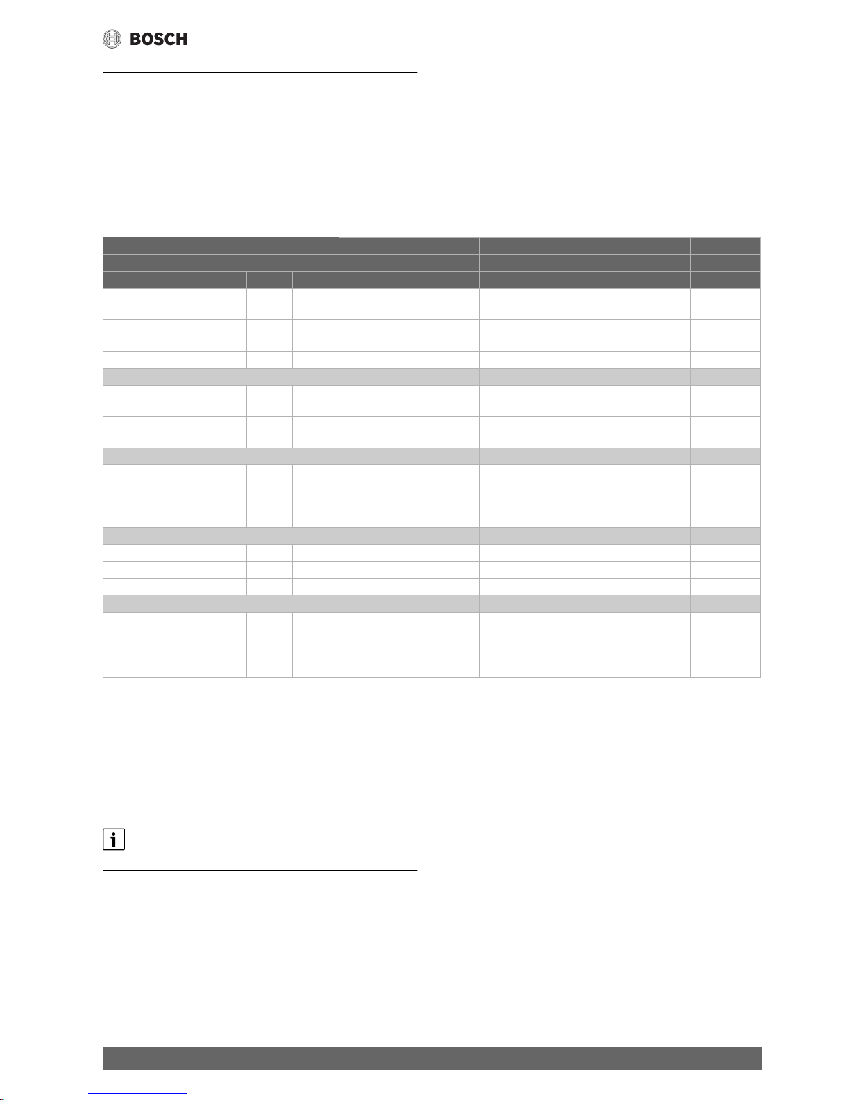
The following product data satisfy the requirements of the EU Regulations No. 811/2013, No. 812/2013, No. 813/2013 and No. 814/2013
supplementing Directive 2010/30/EU.
Table 2 Product data for energy consumption
2.3 Water quality (fill and top-up water)
▶ For information regarding the water quality, see the enclosed
operator's log "Water quality requirements for heat sources made
from aluminium".
Do not use softened water as fill and top-up water.
2.4 Product overview
The Condens 7000 F is a floor standing condensing boiler with an
aluminium heat exchanger.
Right-hand version 8732909990 8732909991 8732909992 8732909993 8732909994 8732909995
Left-hand version 8732909996 8732909997 8732909998 8732909999 8732910000 8732910001
Product data Symbol Unit
Product type – – Condens
7000 F-75
Condens
7000 F-100
Condens
7000 F-150
Condens
7000 F-200
Condens
7000 F-250
Condens
7000 F-300
Floor standing condensing
boiler
– – Yes Yes Yes Yes Yes Yes
Nominal heat output P
rated
kW 69 93 140 186 233 280
Available heat output
At rated output and hightemperature operation
1)
1) High temperature operation means a return temperature of 60 °C at the boiler inlet, and a flow temperature of 80 °C at the boiler outlet.
P
4
kW 69.4 93.0 139.8 186.2 233.1 280.0
At 30 % of rated output and
low-temperature operation
2)
2) Low temperature operation means a return temperature (at the boiler inlet) of 30 °C for floor standing condensing boilers, of 37 °C for floor standing boilers,
and 50 °C for other boilers
P
1
kW 23.1 31.0 46.5 62.1 77.7 93.0
Useful efficiency
At rated output and hightemperature operation
1)
4
% 88.3 88.1 88.1 88.3 88.2 88.3
At 30 % of rated output and
low-temperature operation
2)
1
% 97.8 98.0 97.7 98.1 98.0 97.7
Auxiliary power consumption
At full load el
max
kW 0.083 0.156 0.250 0.234 0.298 0.336
At part load el
min
kW 0.028 0.032 0.046 0.048 0.049 0.057
In standby mode P
SB
kW 0.009 0.009 0.009 0.009 0.009 0.009
Other data
Standby heat loss P
stby
kW 0.161 0.161 0.183 0.247 0.261 0.298
Energy consumption of the
ignition flame
P
ign
kW – – – – – –
NOx emissions NOx mg/kWh 41 49 34 36 32 36
Page 6
Product Information
Condens 7000 F – 6720871579 (2018/07)
6
2.4.1 Product Description
The main Condens 7000 F components are:
• Control unit
• Boiler block
• Appliance frame and casing
• Gas burner
The control unit monitors and controls all electrical boiler components.
The boiler block transfers the heat generated by the burner to the
heating water. The thermal insulation reduces the radiation and standby
losses.
The control unit enables the standard operation of the heating system.
For this, it makes the following functions available, including:
• Switching the heating system on/off
• Setting the DHW temperature and the maximum boiler temperature
in heating mode
• Status display
This floor standing boiler can be operating via the CC 8313 or MX25
control unit.
Many additional functions that enhance control and operating
convenience as well as information on the heating system settings are
described in the corresponding Technical documentation of the
installed control unit.
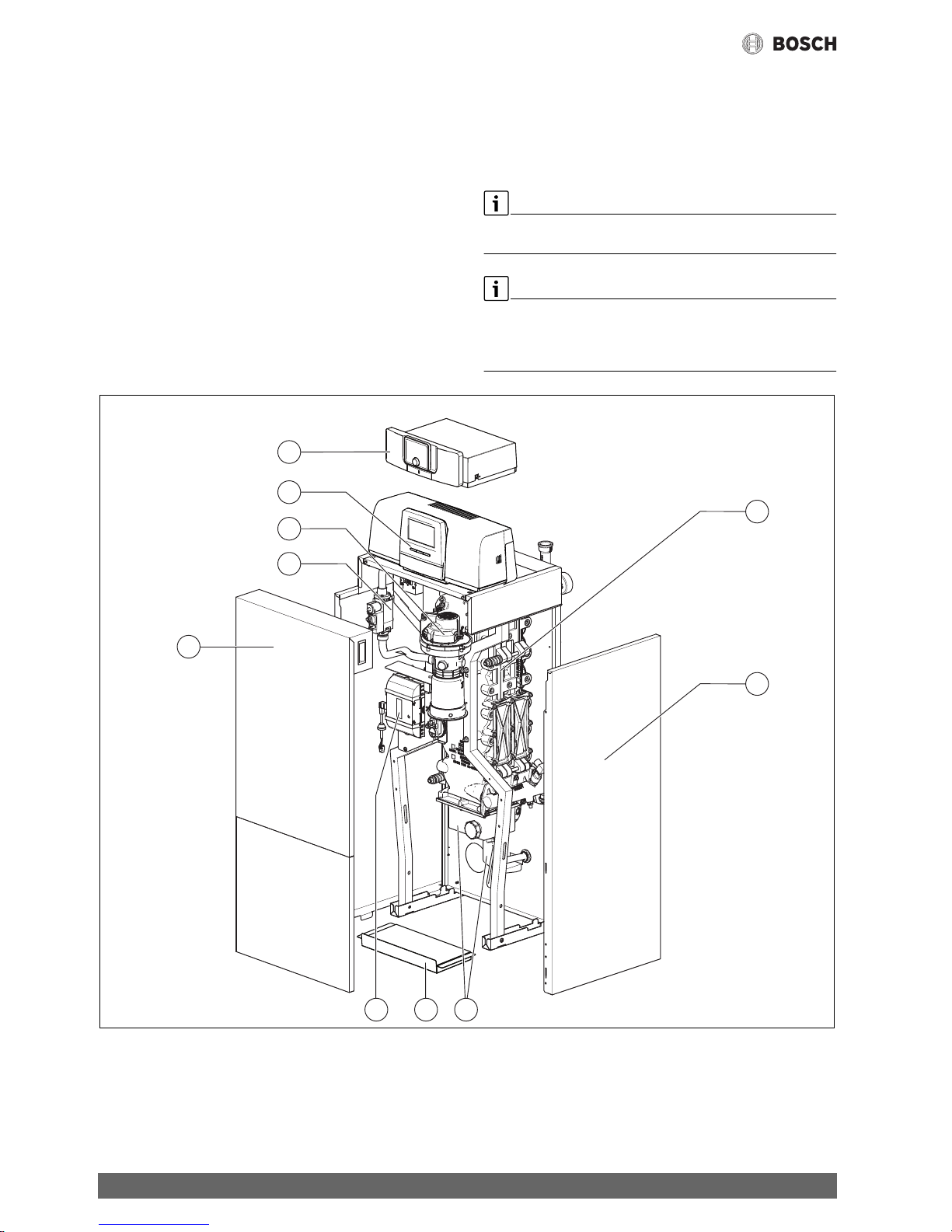
Fig. 1 Condens 7000 F, 75...100 kW main components (shown: right-hand version; cleaning cover and flow and return are located on the right)
[1] Boiler front panel (2-part)
[2] Gas valve
[3] Gas burner with burner rod
[4] Control unit CC 8313 (optional)
[5] MX25 control unit (optional)
[6] Boiler block with thermal insulation
[7] Boiler casing
[8] Condensation catch pan and siphon
[9] Bottom panel
[10] Burner control unit
0010014182-001
6
7
4
5
3
2
1
810 9
Page 7

Product description of optional control units
7
Condens 7000 F – 6720871579 (2018/07)
Fig. 2 Condens 7000 F, 150...300 kW main components (shown: right-hand version; cleaning cover and flow and return are located on the right)
[1] Boiler front panel (2-part)
[2] Gas valve
[3] Gas burner with burner rod
[4] Control unit CC 8313 (optional)
[5] MX25 control unit (optional)
[6] Boiler block with thermal insulation
[7] Boiler casing
[8] Condensation catch pan and siphon
[9] Bottom panel
[10] Burner control unit
The right-hand versions of the boiler are shown. In this case the cleaning
cover and the flow and return are located on the right.
In the left-hand version, the cleaning cover and flow and return are
located on the left.
2.4.2 The heating system is operated and monitored via App
or Web Portal
We offer, in combination with the relevant control unit, a comprehensive
range of products for monitoring, diagnosis and control of the floor
standing boiler via mobile terminal devices, PC or tablet.
3 Product description of optional control units
3.1 Product description of optional control units
The Condens 7000 F is equipped with a control unit that was assigned
when ordering.
A brief description of the optional control units follows. Additional
functions that enhance control and operating convenience as well as
information on the heating system settings are described in the
corresponding Technical documentation of the installed control unit.
3.2 Switching on the boiler at the control unit
▶ To commission the control unit, observe the technical
documentation for the specific control unit.
To avoid frequent cycling of the burner and to ensure efficient operation,
the heating curve should generally be set as low as possible.
0010014184-001
9
6
7
4
5
3
2
1
810
Page 8

MX25 control unit
Condens 7000 F – 6720871579 (2018/07)
8
4 MX25 control unit
4.1 MX25 control unit
Fig. 3 Control unit MX25 with user interface – control elements
[1] Main power switch
[2] Appliance fuse 6.3 A
[3] fav key (favourites functions)
[4] man key (manual operation)
[5] auto key (automatic mode)
[6] menu key (to call up menus)
[7] info key (info menu and help)
[8] Back key
[9] Network connection
(RJ45, only available with IP inside control units)
[10] Selector
[11] Flue gas inspector, reset and emergency operation key
[12] Status-LED
[13] Service key connection
The MX25 control unit enables the standard operation of the
heating system.
The following functions are available for this:
• Activation of chimney sweep mode
• Status displays for boiler and burner operation
• Reset of locking faults
• Activation of emergency operation (manual operation)
The user interface offers many additional functions for conveniently
controlling the heating system via the CW 400/CW 800 user interface or
the CR 100 and CR 10 (available separately).
0010004473-002
1 543 8
11 10
9
13 12
762
Page 9

MX25 control unit
9
Condens 7000 F – 6720871579 (2018/07)
4.2 Overview of control elements
If the display lighting is off, pressing any control element for the first time
activates the lighting only. The descriptions of the steps to be carried out
by the operator in these instructions always assume that the lighting is
activated. If no control element is actuated, the lighting turns off
automatically.
Fig. 4 Control elements
[1] fav key – Press briefly to call up and hold pressed to configure
favourites functions
[2] man key – Press briefly to activate manual operation
and hold pressed to set duration for manual operation
[3] auto key – Activate automatic mode
[4] menu key – Press briefly to open the main menu
and hold pressed to open the service menu
[5] info key – Displays the info menu for information
about the current selection
[6] Back key – Returns to previous menu or discards a value
(press briefly); returns to the standard display (hold down)
[7] Control knob – Selects (turn) and Confirms (press)
4.3 Switching on the boiler
▶ Switching on the boiler at the ON/OFF switch [1].
The display lights up and shows the appliance temperature after a
short time.
Fig. 5 Main power switch
[1] Main power switch
4.4 Switching the heating on or off
NOTICE:
Risk of damage to the system from frost!
When heating mode is switched off and in summer mode, only device
frost protection exists.
▶ Observe the need for frost protection if there is a risk of frost.
▶ Open Main menu.
▶ Select and confirm the Heat source menu.
▶ Select and confirm Heating.
▶ Select and confirm On or Off.
Fig. 6 Switching heating on
▶ To select manual summer mode, go to the menu Main menu >
Heating > Sum./wint. changeover and select the setting Sum./
wint. changeover under the menu item Permanently summer.
The heating is off and DHW heating is active in summer mode.
For more information on summer mode see the technical
documentation of the user interface.
0010005432-001
auto
man
fav
menu
info
5
6
7
4
2
3
1
0010004475-001
1
0010005615-001
Page 10

CC8313 control unit
Condens 7000 F – 6720871579 (2018/07)
10
5 CC8313 control unit
5.1 Control elements of the control unit and the user interface
Fig. 7 Control elements
[1] Touch screen
[2] Activation Code (registration code)
[3] Reset button (e.g. high limit safety cut-out, SAFe)
[4] Flue gas inspector key (for flue gas test)
[5] Manual operation key
[6] USB interface (e.g. for service purposes)
[7] LED status display
[8] Type plate
[9] F1-, F2 circuit breaker
[10] Appliance on/off switch
5.2 Function buttons and system status
Function buttons
The function buttons enable
• Manual operation
• Flue gas test
• Reset (e.g. high limit safety cut-out, SAFe)
System status, function status, component status
The status of the system, the functions and system components is
displayed via the Function status display ( Fig. 9, [1], page 12), the
System components status display ( Fig. 9, [15], page 12) and the
LED status display ( Fig. 7, [7], page 10):
• Green = system in automatic mode
• Yellow = system in manual mode, Flue gas testFlue gas test,
Service displayService display or Blocking faultBlocking fault
SAFe
• Yellow flashing = Control unit couplingControl unit coupling
• Red = FaultFault
5.2.1 ResetReset key
When the key is pressed the locking fault is unlocked and the
functions are reset (e.g. following triggering of the high limit safety
cut-out or resetting of the SAFe).
To unlock a function:
▶ Key Hold down for 2 seconds.
0010005509-001
1
3 26 45
7
9
10
8
reset
rese
t
rese
t
rese
t
Page 11

CC8313 control unit
11
Condens 7000 F – 6720871579 (2018/07)
5.2.2 Flue gas inspector key (flue gas test)
WARNING:
Risk of scalding from hot water!
Setting the set temperature > 60 °C creates a risk of scalding.
▶ Do not draw off DHW unmixed.
To perform the flue gas test:
▶ Observe the relevant national requirements for limiting flue losses
from the heating system.
The flue gas test is switched on if required at the heat source
( Technical documentation of heat source) or at the control unit.
▶ Ensure heat consumption within the heating system.
▶ Starting from the initial position, hold the key down for several
seconds.
The flue gas test starts immediately.
The parameters for defining the conditions under which the flue gas
test is carried out are shown in the display.
▶ Setting parameters (e.g. modulation).
▶ Tap Save.
The heat source is operated at the set output.
If a preset parameter (e.g. minimum boiler output) is exceeded or
undercut when making the adjustment, a warning message appears that
must be confirmed. The parameter remains at the previous value.
To exit the view:
▶ Tap cancel.
The flue gas test continues.
Fig. 8 Flue gas test
[1] Save
[2] Cancel
[3] Modulation
The LED status display ( Fig. 7, [7], page 10) lights up yellow during
the flue gas test and is accompanied by a constantly recurring pop-up
window.
To conclude the flue gas test:
▶ Press key again.
If the flue gas test is not ended manually, it ends automatically after 30
minutes.
5.2.3 Key for manual operation, emergency operation
WARNING:
Risk of scalding from hot water!
Setting the set temperature > 60 °C creates a risk of scalding.
▶ Do not draw off DHW unmixed.
Key for manual operation
Press the key to ensure a manual operation if, for example, the user
interface has dropped out or the internal controller communication is
disrupted. The heat source heats continuously without setback at a
boiler temperature of 60 °C. The pumps and mixers of the heating
circuits, the DHW heating of the central module and the function
modules continue running normally. The LED status display lights up
yellow.
Manual operation
The manual operation operating mode can be set and adjusted for every
function separately.
▶ Observe the operating instructions of the control unit.
Emergency mode
The emergency operation is activated automatically if the user
interface is faulty or if communication with the control unit via the
internal BUS is interrupted.
During emergency operation, the heat source heats continuously
without setback at a boiler temperature of 60 °C. All pumps connected to
the central module (boiler circulation pump, pump of heating circuit 00,
DHW pump and DHW circulation pump) are switched on.
The SR mixing valve is de-energised and must be adjusted manually if
necessary. The installed function modules cannot be triggered by the
user interface BCT531 and do not work.
In emergency operation the LED status display lights up red.
5.3 Operating and display elements of the touch screen
The display and selectability of the menu items depends on which
modules are inserted and which settings have been made.
The following displays can be called up via the touch screen:
• Heat source in the system
• Heat consumers and heat distributors in the system
• Monitor data
• Setting parameters for commissioning and system optimisation.
These parameters are protected by a key code.
0010009474-001
77
3
2
1
Page 12

CC8313 control unit
Condens 7000 F – 6720871579 (2018/07)
12
Fig. 9 Operating and display elements
[1] Display of system, subsystem or function
[2] Status display of active menu level
[3] Display of temperature set (set temperature)
[4] Display of operating mode set
[5] Display of time program set
[6] Display of Internet connection
[7] Display of system components
[8] Advanced functions for heating circuit, DHW
[9] Display of time
[10] Press field to switch between display types on the display
[11] Information menu
[12] Press field to go back to the previous level/screen
[13] Press field to return to the system overview
[14] Advanced functions of the heat source
[15] Status display of system components
The symbols used are listed in Fig. 7 on page 10, accompanied by an
explanation.
5.4 Operating the appliance
5.4.1 Control system
The display and operation is organised in several menu levels. These can
be accessed by tapping the corresponding symbol. Several menu levels
can only be accessed by contractors. If an arrow is displayed on the right
or left of the selected menu ( Fig. 9, page 12) additional menu items
are available. The corresponding status of the system, part of the
system, function or system components can be identified from the
individual images displayed.
Further information:
• Menu structure Chapter 3.1, from page 7
• Functions Chapter 3.1, from page 7
• Explanation of symbols and keys Chapter 3.1, from page 7
Tap and swipe the touch screen to navigate through the menu levels and
operate the functions.
To go back to the previous level/screen:
▶ Tap symbol.
12:00
50 °C
on/o
30 %
1 2 3 4 5 6
9
7
8
10111213
14
15
0010005510-001
Page 13

CC8313 control unit
13
Condens 7000 F – 6720871579 (2018/07)
5.4.2 Switch on and enable control unit
▶ Switch on control unit at ON/OFF switch ( Fig. 7, [10], page 10).
The standard display appears following initialisation of the control
unit, or if there has been no user activity at the display for some time.
Fig. 10 Standard display
[1] Boiler Temperature
[2] Continue to overview
The boiler temperature is displayed and the display is disabled in the
standard display. To reduce the current consumption of the
control unit, the display changes to sleep mode after several minutes.
When this happens the display becomes darker.
To activate the display:
▶ Tap the display.
To enable the display:
▶ Tap Continue to overview.
The system name of the control unit series appears briefly after the
display is enabled. The start page is then displayed with the system
overview.
To display the system overview:
▶ Tap the display.
Fig. 11 System Overview
5.4.3 Lock screen
The main menu can be protected from unauthorised access using a
4-digit password. The block can only be set up and removed by
customer service.
If the display remains untouched for a longer period, the main menu is
disabled. The password is requested the next time the display is
touched.
If the password is lost the block can only be removed by customer
service.
5.4.4 Calling up menu levels or functions
To call up individual menu levels or select functions:
▶ Tap the corresponding position on the display with your finger.
Fig. 12 Calling up a menu level or function
[1] Heat production
[2] Status display
[3] System
[4] Fault history
The next menu level or function is displayed.
Kesseltemp. 75°
1
2
0010007852-001
0010009266-001
12:00
0010006521-001
12:00
321
4
Page 14

CC8313 control unit
Condens 7000 F – 6720871579 (2018/07)
14
Menu levels
If several menus or functions are available at one level:
▶ Tap the corresponding position (function) on the display with your
finger.
Fig. 13 Heating circuit overview (example)
[1] System > Control unit 01
[2] Domestic hot water
[3] Heating circuit 03
[4] Heating circuit 01
[5] Heating circuit 04
[6] Heating circuit 02
[7] Heating circuit 05
[8] Heating circuit 07
[9] Heating circuit 06
To select a different function within a menu level:
▶ Tap the right or left arrow on the display with your finger.
-or-
▶ Swipe to the left or right across the display with your finger.
Fig. 14 Scrolling
-or-
▶ Swipe your finger across the display.
Fig. 15 Wipe
Display of heating circuits
Designations are allocated to the heating circuits depending on the slot
of the heating circuit module. The heating circuits are numbered
according to the sequence of slots. This means that the heating circuits
at slot 1 are displayed as heating circuit 01 and 02. The heating circuits
at slot 2 are displayed as 03 and 04. If a different module is inserted at a
slot, these heating circuit numbers are omitted. If the heating circuit has
been given a name, this is displayed.
5.4.5 Calling up submenus
Observe technical documentation of the installed control unit.
5.4.6 Information menu
To display information about the installation or the system:
▶ Tap symbol.
▶ Tap the required area in the Info menu.
Fig. 16 Overview of Info menu
Depending on the area, the following information is e.g. displayed:
• Statuses of safety equipment
• Temperatures
• Operating modes
• Hours run
0010006525-001
12:00
1 2 3 4
89
5 6 7
0010006536-001
12:00
50 °C
on/o
30 %
0010006537-001
12:00
50 °C
on/o
30 %
0010009883-001
12:00
i
Page 15

Commissioning
15
Condens 7000 F – 6720871579 (2018/07)
6 Commissioning
6.1 Checking the operating pressure, topping up the
heating water and venting the system
6.1.1 Checking the operating pressure
Your heating contractor will have set the red needle of the pressure
gauge [1] to the required operating pressure (at least 1 bar) and will
have recorded this value in table 8, page 14.
▶ Check that the pressure gauge needle [2] is within the green
band [3}.
▶ If the pressure gauge needle drops below the green band, top up the
heating water.
Fig. 17 Pressure gauge for sealed systems
[1] Red needle
[2] Pressure gauge needle
[3] Green marking
Table 3 Operating pressure (entered by the heating contractor)
6.1.2 Topping up the heating water and venting the system
CAUTION:
Health risk through contaminated drinking water!
▶ Obser ve all country-specific regulations and standards regarding the
prevention of drinking water contamination.
▶ In Europe, observe standard EN 1717.
NOTICE:
Material damage due to thermal stresses!
When topping up a hot boiler with cold heating water, thermal
stresses can lead to cracking due to internal stress.
▶ Only fill the heating system when cold. Maximum flow
temperature 40 °C.
NOTICE:
System damage due to frequent topping up!
If you have to top up the heating water frequently, the heating system
may suffer damage through corrosion or scaling, depending on the water
quality.
▶ Ask a certified heating contractor if the local water can be used
untreated or whether it needs to be treated.
▶ Notify your heating contractor if you frequently need to top up your
heating system.
Topping up heating water is different for individual heating systems.
Therefore, ask your approved contractor to advise you accordingly.
The refill quantities must be documented in the operator's log.
6.2 Switching on the heating system
Observe technical documentation of the installed control unit.
Before switching on (Chapter 3.1), ensure that:
• the operating pressure is high enough,
• the fuel supply has been turned on at the main shut-off valve, and
• the heating system emergency stop switch is switched on.
7 Shutting down the heating system
7.1 Shutting down the heating system via the control unit
NOTICE:
Frost damage!
If the heating system is not standing in a frost-proof room and is not in
operation, it may freeze up when exposed to frost. In summer mode or if
heating mode is blocked, only the device frost protection remains active.
▶ Leave the heating system switched on at all times whenever possible,
and set the flow temperature to at least 30 °C,
-or-
▶ Protect the heating system against frost by having the heating and
DHW pipes drained by a contractor from the lowest point.
▶ Shutting down the heating system via the ON/OFF switch at the
control unit (Chapter 3.1).
7.2 Shutting down the heating system in an emergency
Only use the boiler room circuit breaker or heating system emergency
stop switch to switch off the heating system in an emergency.
▶ Never risk your own life. Your own safety is paramount.
▶ Close off the fuel supply installed on site.
▶ Isolate the heating system from the mains power supply via the
heating system emergency stop switch or the main circuit breaker.
Operating pressure
Set operating pressure (optimum
value) _____________ bar
6 720 615 876-59.2T
3
2
1
Page 16

Environmental protection/disposal
Condens 7000 F – 6720871579 (2018/07)
16
8 Environmental protection/disposal
Environmental protection is a fundamental corporate strategy of the
Bosch Group.
The quality of our products, their economy and environmental safety are
all of equal importance to us and all environmental protection legislation
and regulations are strictly observed.
We use the best possible technology and materials for protecting the
environment taking account of economic considerations.
Packaging
Where packaging is concerned, we participate in country-specific
recycling processes that ensure optimum recycling.
All of our packaging materials are environmentally compatible and can be
recycled.
Used appliances
Used appliances contain valuable materials that can be recycled.
The various assemblies can be easily dismantled. Synthetic materials are
marked accordingly. Assemblies can therefore be sorted by composition
and passed on for recycling or disposal.
Used electrical and electronic appliances
Electrical or electronic devices that are no longer
serviceable must be collected separately and sent for
environmentally compatible recycling (in accordance with
the European Waste Electrical and Electronic Equipment
Directive).
To dispose of old electrical or electronic devices, you
should use the return and collection systems put in place in the country
concerned.
Batteries must not be disposed together with your household waste.
Used batteries must be disposed of in local collection systems.
9 Inspection and maintenance
9.1 What makes regular service important?
Heating systems should be regularly serviced for the following reasons:
• To maintain a high level of efficiency and to operate the heating
system economically (low fuel consumption)
• To achieve a high level of operational reliability
• To maintain the cleanest possible combustion
NOTICE:
Material damage due to a lack of or incorrect cleaning and service.
▶ Have the heating system inspected, maintained and cleaned once a
year by a certified heating contractor.
▶ We recommend you enter a contract covering an annual inspection
and demand-based maintenance.
9.2 Cleaning and care
To clean the boiler:
▶ Do not use abrasive or aggressive cleaning agents.
▶ Clean the casing with a damp cloth (soapy solution).
10 Troubleshooting
10.1 Recognising the operating condition and clearing
faults
NOTICE:
Frost damage!
If the heating system is not standing in a frost-proof room and is not in
operation, it may freeze up when exposed to frost. In summer mode or if
heating mode is blocked, only the device frost protection remains active.
▶ Leave the heating system switched on at all times whenever possible,
and set the flow temperature to at least 30 °C,
-or-
▶ Protect the heating system against frost by having the heating and
DHW pipes drained by a contractor from the lowest point.
If a fault has developed, the fault code flashes on the control unit display.
For more information on rectifying the problem or on possible faults,
refer to the corresponding technical documentation of the installed
control unit.
If the fault cannot be cleared:
▶ Note down the fault message and notify a heating contractor.
Page 17

Page 18

Page 19

Page 20

Bosch Thermotechnik GmbH
Sophienstrasse 30-32
D-35576 Wetzlar
www.bosch-industrial.com
 Loading...