

Bosch Condens 2000F30 Regular, Condens 2000F16 Regular, Condens 3000F30 System, Condens 2000F42 Regular, Condens 3000F16 System Installation, Commissioning And Servicing Instruction Manual
Page 1
Installation, Commissioning and Servicing Instruction manual
Floor-standing gas-fired condensing appliance
Condens
6720809859-00.1Wo
2000F16, 30, 42 Regular boiler/3000F 16, 30 System boiler
6 720 816 930 (2015/04)
Page 2

Contents
Condens – 6720816930 (2015/04)
2
Contents
1 Key to symbols and safety precautions . . . . . . . . . . . . . . . . . . . 3
1.1 Key to symbols . . . . . . . . . . . . . . . . . . . . . . . . . . . . . . . . . . 3
1.2 Legislation and regulations . . . . . . . . . . . . . . . . . . . . . . . . 3
2 Appliance information . . . . . . . . . . . . . . . . . . . . . . . . . . . . . . . . . 4
2.1 General information . . . . . . . . . . . . . . . . . . . . . . . . . . . . . 4
2.2 Intended use . . . . . . . . . . . . . . . . . . . . . . . . . . . . . . . . . . . 4
2.3 Declaration of conformity . . . . . . . . . . . . . . . . . . . . . . . . . 4
2.4 Type plate . . . . . . . . . . . . . . . . . . . . . . . . . . . . . . . . . . . . . 4
2.5 Type overview . . . . . . . . . . . . . . . . . . . . . . . . . . . . . . . . . . 4
2.5.1 Electrical supply . . . . . . . . . . . . . . . . . . . . . . . . . . . . . . . . 4
2.5.2 Gas supply . . . . . . . . . . . . . . . . . . . . . . . . . . . . . . . . . . . . . 4
2.6 Dimensions and description . . . . . . . . . . . . . . . . . . . . . . . 5
2.7 Regular boiler layout and components . . . . . . . . . . . . . . . 6
2.8 Regular boiler wiring diagram . . . . . . . . . . . . . . . . . . . . . . 7
2.9 Regular boiler Technical data . . . . . . . . . . . . . . . . . . . . . . 8
2.10 Gas type and installation type . . . . . . . . . . . . . . . . . . . . . 9
2.11 Output power reduction due to altitude . . . . . . . . . . . . . . 9
2.12 System boiler layout and components . . . . . . . . . . . . . 11
2.13 System boiler wiring diagram . . . . . . . . . . . . . . . . . . . . 12
2.14 System boiler Technical data . . . . . . . . . . . . . . . . . . . . 13
3 Regulations . . . . . . . . . . . . . . . . . . . . . . . . . . . . . . . . . . . . . . . . 15
3.1 Country specific regulations . . . . . . . . . . . . . . . . . . . . . 15
3.2 Approvals and notifications . . . . . . . . . . . . . . . . . . . . . 15
3.3 Quality of the heating water . . . . . . . . . . . . . . . . . . . . . 15
3.4 Connection to combustion air and flue gas systems . . 15
3.5 Room air dependent operation . . . . . . . . . . . . . . . . . . . 15
3.6 Flue gas systems type Bxx . . . . . . . . . . . . . . . . . . . . . . 15
3.7 Flue gas systems type Cxx . . . . . . . . . . . . . . . . . . . . . . 15
3.8 Combustion air quality . . . . . . . . . . . . . . . . . . . . . . . . . 15
3.9 Disposal . . . . . . . . . . . . . . . . . . . . . . . . . . . . . . . . . . . . . 16
3.10 Inspection, service and maintenance . . . . . . . . . . . . . 16
4 Pre-installation . . . . . . . . . . . . . . . . . . . . . . . . . . . . . . . . . . . . . 16
4.1 Cleaning primary systems . . . . . . . . . . . . . . . . . . . . . . . 16
4.2 Hydraulic connections . . . . . . . . . . . . . . . . . . . . . . . . . 16
4.2.1 Connecting flow and return . . . . . . . . . . . . . . . . . . . . . 16
4.2.2 Expansion vessel and drain valve . . . . . . . . . . . . . . . . . 17
4.3 Water systems and pipework . . . . . . . . . . . . . . . . . . . . 17
4.4 Condensate drain . . . . . . . . . . . . . . . . . . . . . . . . . . . . . 17
4.4.1 To remove the condensate trap . . . . . . . . . . . . . . . . . . 17
4.5 Boiler location and clearances . . . . . . . . . . . . . . . . . . . 17
4.5.1 Installation . . . . . . . . . . . . . . . . . . . . . . . . . . . . . . . . . . . 17
4.5.2 Installations and servicing clearances: . . . . . . . . . . . . 17
5 Installation . . . . . . . . . . . . . . . . . . . . . . . . . . . . . . . . . . . . . . . . . 18
5.1 Unpacking the boiler . . . . . . . . . . . . . . . . . . . . . . . . . . . 18
5.2 Boiler room requirements . . . . . . . . . . . . . . . . . . . . . . . 18
5.2.1 Installing the levelling feet . . . . . . . . . . . . . . . . . . . . . . 18
5.2.2 Positioning the appliance . . . . . . . . . . . . . . . . . . . . . . . 19
5.3 Mounting the boiler and flue opening . . . . . . . . . . . . . . 19
5.4 Flue options . . . . . . . . . . . . . . . . . . . . . . . . . . . . . . . . . . 20
5.5 Vertical flues . . . . . . . . . . . . . . . . . . . . . . . . . . . . . . . . . 21
6 Electrical . . . . . . . . . . . . . . . . . . . . . . . . . . . . . . . . . . . . . . . . . . . 23
6.1 Electrical . . . . . . . . . . . . . . . . . . . . . . . . . . . . . . . . . . . . 23
7 Commissioning . . . . . . . . . . . . . . . . . . . . . . . . . . . . . . . . . . . . . 24
7.1 Pre-Commissioning checks . . . . . . . . . . . . . . . . . . . . . 24
7.2 Filling the system and checking for leaks . . . . . . . . . . . 24
7.3 Water treatment . . . . . . . . . . . . . . . . . . . . . . . . . . . . . . 25
7.4 Starting the appliance . . . . . . . . . . . . . . . . . . . . . . . . . . 25
7.5 Checking gas inlet pressure . . . . . . . . . . . . . . . . . . . . . 26
7.5.1 Measuring the inlet pressure . . . . . . . . . . . . . . . . . . . . 26
7.5.2 Checking the gas rate . . . . . . . . . . . . . . . . . . . . . . . . . . 26
7.6 Finishing commissioning . . . . . . . . . . . . . . . . . . . . . . . 26
7.7 Commissioning checklist . . . . . . . . . . . . . . . . . . . . . . . 27
8 Thermal disinfection . . . . . . . . . . . . . . . . . . . . . . . . . . . . . . . . . 28
8.1 Perform thermal disinfection . . . . . . . . . . . . . . . . . . . . 28
8.2 Thermal disinfection for system with a hot water tank 28
9 Operating the appliance . . . . . . . . . . . . . . . . . . . . . . . . . . . . . . 29
9.1 Controls overview . . . . . . . . . . . . . . . . . . . . . . . . . . . . . 29
9.2 Screen display . . . . . . . . . . . . . . . . . . . . . . . . . . . . . . . . 29
9.3 Appliance on/off switch . . . . . . . . . . . . . . . . . . . . . . . . 29
9.4 Heating mode . . . . . . . . . . . . . . . . . . . . . . . . . . . . . . . . 30
9.4.1 Heating mode on/off . . . . . . . . . . . . . . . . . . . . . . . . . . . 30
9.4.2 Set the maximum flow temperature . . . . . . . . . . . . . . . 30
9.5 Setting the DHW . . . . . . . . . . . . . . . . . . . . . . . . . . . . . . 31
9.5.1 DHW on/off . . . . . . . . . . . . . . . . . . . . . . . . . . . . . . . . . . 31
9.5.2 Setting the DHW temperature . . . . . . . . . . . . . . . . . . . 31
9.6 Control unit setting . . . . . . . . . . . . . . . . . . . . . . . . . . . . 31
9.7 Summer mode ON/OFF . . . . . . . . . . . . . . . . . . . . . . . . 32
9.8 Setting frost protection . . . . . . . . . . . . . . . . . . . . . . . . 32
10 Servicing and spares . . . . . . . . . . . . . . . . . . . . . . . . . . . . . . . . . 33
10.1 Inspection and service . . . . . . . . . . . . . . . . . . . . . . . . . 33
10.2 Service function . . . . . . . . . . . . . . . . . . . . . . . . . . . . . . 33
10.2.1 Selecting service menus . . . . . . . . . . . . . . . . . . . . . . . . 33
10.2.2 Selecting the Information menu . . . . . . . . . . . . . . . . . . 34
10.2.3 Selecting menu 1 . . . . . . . . . . . . . . . . . . . . . . . . . . . . . . 34
10.2.4 Selecting menu 2 . . . . . . . . . . . . . . . . . . . . . . . . . . . . . . 34
10.2.5 Selecting menu 3 . . . . . . . . . . . . . . . . . . . . . . . . . . . . . . 36
10.2.6 Selecting the Test menu . . . . . . . . . . . . . . . . . . . . . . . . 36
10.2.7 Setting the boiler to maximum output . . . . . . . . . . . . . 37
10.3 Flue integrity . . . . . . . . . . . . . . . . . . . . . . . . . . . . . . . . . 37
10.4 Service inspection - Component access . . . . . . . . . . . 37
10.4.1 Control panel - Service position . . . . . . . . . . . . . . . . . . 38
10.5 Checking the gas inlet pressure . . . . . . . . . . . . . . . . . . 38
10.6 Fan pressure test . . . . . . . . . . . . . . . . . . . . . . . . . . . . . 38
10.7 Flue gas analysis . . . . . . . . . . . . . . . . . . . . . . . . . . . . . . 39
10.8 Setting the air/gas ratio . . . . . . . . . . . . . . . . . . . . . . . . 40
10.9 Cleaning the heat exchanger . . . . . . . . . . . . . . . . . . . . 40
10.10 Inspection and servicing checklist . . . . . . . . . . . . . . . . 42
10.11 Demand dependant maintenance . . . . . . . . . . . . . . . . 44
11 Replacement parts . . . . . . . . . . . . . . . . . . . . . . . . . . . . . . . . . . 45
11.1 Replacement parts . . . . . . . . . . . . . . . . . . . . . . . . . . . . 45
11.1.1 Access to components . . . . . . . . . . . . . . . . . . . . . . . . . 45
11.1.2 Fan assembly . . . . . . . . . . . . . . . . . . . . . . . . . . . . . . . . . 46
11.1.3 Sensors . . . . . . . . . . . . . . . . . . . . . . . . . . . . . . . . . . . . . 47
11.1.4 To remove the condensate trap . . . . . . . . . . . . . . . . . . 47
11.1.5 Gas Valve . . . . . . . . . . . . . . . . . . . . . . . . . . . . . . . . . . . . 47
11.1.6 Primary Heat Exchanger . . . . . . . . . . . . . . . . . . . . . . . . 48
12 Fault finding and dianostics . . . . . . . . . . . . . . . . . . . . . . . . . . 49
12.1 Status codes and faults . . . . . . . . . . . . . . . . . . . . . . . . . 49
12.2 Troubleshooting . . . . . . . . . . . . . . . . . . . . . . . . . . . . . . 49
12.3 Information and service menus . . . . . . . . . . . . . . . . . . 49
12.3.1 Selecting the information menu . . . . . . . . . . . . . . . . . . 51
12.3.2 Selecting service menus . . . . . . . . . . . . . . . . . . . . . . . . 52
12.3.3 Menu 1 - System parameters . . . . . . . . . . . . . . . . . . . . 52
12.3.4 Menu 2 - Boiler parameters . . . . . . . . . . . . . . . . . . . . . 52
12.3.5 Reset to factory settings . . . . . . . . . . . . . . . . . . . . . . . . 53
12.3.6 Menu 3 - Boiler maximum & minimum limits . . . . . . . . 53
12.3.7 Using the test menu . . . . . . . . . . . . . . . . . . . . . . . . . . . 54
12.4 Fault codes . . . . . . . . . . . . . . . . . . . . . . . . . . . . . . . . . . 56
Page 3
Key to symbols and safety precautions
Condens – 6720816930 (2015/04)
3
1 KEY TO SYMBOLS AND SAFETY PRECAUTIONS
1.1 Key to symbols
Warnings
The following keywords are defined and can be used in this document:
• NOTICE indicates a situation that could result in damage to property
or equipment.
• CAUTION indicates a situation that could result in minor to medium
injury.
• WARNING indicates a situation that could result in severe injury or
death.
• DANGER indicates a situation that will result in severe injury or
death.
Appliance operation:
This appliance can be used by children aged from 8 years and above and
persons with reduced physical, sensory or mental capabilities or lack of
experience and knowledge if they have been given supervision or
instruction concerning use of the appliance in a safe way and understand
the hazards involved. Children shall not play with the appliance.
Cleaning and user maintenance shall not be made by children without
supervision.
Important information
Additional symbols
Symbols used in the manual
Please read these instructions carefully before starting installation.
If you smell gas
A gas leak could potentially cause an explosion. If you smell gas, observe
the following rules.
▶ Prevent flames or sparks:
– Do not smoke, use a lighter or strike matches.
– Do not operate any electrical switches or unplug any equipment.
– Do not use the telephone or ring doorbells.
▶ Turn off the gas at the meter or regulator.
▶ Open windows and doors.
▶ Warn your neighbours and leave the building.
▶ Prevent anyone from entering the building.
▶ Well away from the building, call the Emergency Services.
▶ L.P.G. boilers: Call the supplier’s number on the side of the gas tank.
Combustion and corrosive materials
Do not store or use any combustible materials (paper, thinners, paints
etc.) inside or within the vicinity of the appliance.
Chemically aggressive substances can corrode the appliance and
invalidate any warranty.
Fitting and modification
Flue systems must not be modified in any way other than as described in
the fitting instructions. any misuse or unauthorised modifications to the
appliance, flue or associated components and systems could invalidate
the warranty. The manufacturer accepts no liability arising from any
such actions, excluding statutory rights.
Servicing
Advise the user to have the system serviced annually by a competent
registered engineer. Approved spares must be used to help maintain the
economy, safety, and reliability.
Central heating water
Artificially softened water must not be used to fill the central heating
system.
1.2 Legislation and regulations
Installation regulations
The appliance must be installed by a competent person in accordance
with all the legislation and regulations that are in force at the time of
installation, paying particular attention to any provisions or regulations
made by the local authorities.
Warnings in this document are identified by a warning
triangle printed against a grey background.
Keywords at the start of a warning indicate the type and
seriousness of the ensuing risk if measures to prevent
the risk are not taken.
This symbol indicates important information where
there is no risk to people or property.
Symbol Explanation
▶ Step in an action sequence
Cross-reference to another part of the document
• List entry
– List entry (second level)
Domestic Hot Water
Central Heating
Hot Water Storage Cylinder
Domestic Cold Water Supply
Gas Supply
Ø Diameter
Equal to or less than
Equal to or greater than
< Less than
> Greater than
NG Natural Gas
LPG Liquid Petroleum Gas
CH Central Heating
DHW Domestic Hot Water
DCW Domestic Cold Water
PRV Pressure Relief Valve
NTC Negative Temperature Coefficient (sensor)
IP Ingress Protection
RCD Residual Current Device
TRV Thermostatic Radiator Valve
Table 1 Abbreviations use in this manual
Page 4

4 | Appliance information
Product Name6 720 ... ... (YYYY/MM)
2 Appliance information
2.1 General information
Boiler features and checklist
• Pre-wired and pre-plumbed
• Galvanised steel inner frame
• Bosch EMS control system
• Automatic ignition
• Direct burner ignition electrodes
• Built-in frost protection
• Built-in fault finding diagnostics
• Modulating automatic gas valve
• Combustion air fan with speed regulator
• CH temperature sensor and control
• Flue gas overheat sensor
Fig. 1 Standard package
2.2 Intended use
These appliances may only be used in a closed loop hot water central
heating system.
Any other purpose is considered improper use. Any damage resulting
from misuse is excluded from the manufacturer’s guarantee.
The commercial or industrial use of the appliance to produce process
heat is not permitted.
Only use genuine gas from official gas suppliers.
Ensure the appliance is operated within the limits on the data label and
parameters in this manual.
2.3 Declaration of conformity
This product, in design and operation, conforms to the European
Directives and supplementary national requirements.
Compliance is demonstrated by the CE marking.
You can request the declaration of conformity of the product. To do so,
send your request to the address on the back of the manual.
The appliances meet the requirements for gas-fired condensing boilers
in terms of energy saving regulations.
The appliances are tested according to EN 677.
2.4 Type plate
The type label contains information on device performance, the
registration data and the serial number.
2.5 Type overview
KSBR units, heat only gas-fired condensing boilers with an integrated
circulating pump and optional 3-way valve for the connection of the hot
water tank.
KBR units, heat only, gas-fired condensing boilers without a circulating
pump or optional three way valve, for use in systems where this is
provided externally.
2.5.1 Electrical supply
• Supply: 230V - 50 Hz
• External “Quick blow” 3A fuse
• The appliance must be earthed
• IPX4D
• The wiring between the appliance and the electrical supply must
comply with the latest IEE wiring regulations that apply to wiring a to
a fixed appliance
• Any system connected to the appliance must not have a separate
electrical supply
2.5.2 Gas supply
• Boilers using Natural Gas (NG) must be connected to a governed
meter.
• Liquid Petroleum Gas (LPG) must be connected to a regulator.
• Installation and connection of the gas supply to the boiler must be in
accordance with country and local regulations.
• Under no circumstance should be size of the gas supply pipe be less
than DN20.
• The meter or regulator and pipe work to the meter must be checked,
by the gas supplier. This is to ensure that the equipment is in good
working order and can meet the gas flow and pressure requirements,
in addition to the demand from any other appliance being served.
CHECK LIST - LITERATURE PACK: Qty.
1 Installation, Commissioning and Servicing Instructions 1
Users Instructions
1
Table 2 Literature pack - checklist
CHECK LIST - INSTALLATION PACK: Qty.
2 PRV discharge pipe 1
3 Levelling feet 4
Table 3 Installation pack - checklist
6720809859-47.1Wo
1
2
3
K Floor standing appliance
S Built-in circulation pump & optional 3 way diverter valve
B Condensing technology
R Modulating burner
16 output up to 16 kiloWatts
30 output up to 30 kiloWatts
42 output up to 42 kilowatts
Table 4 Appliance designation
Page 5
Appliance information | 5
6 720 ... ... (YYYY/MM)Product Name
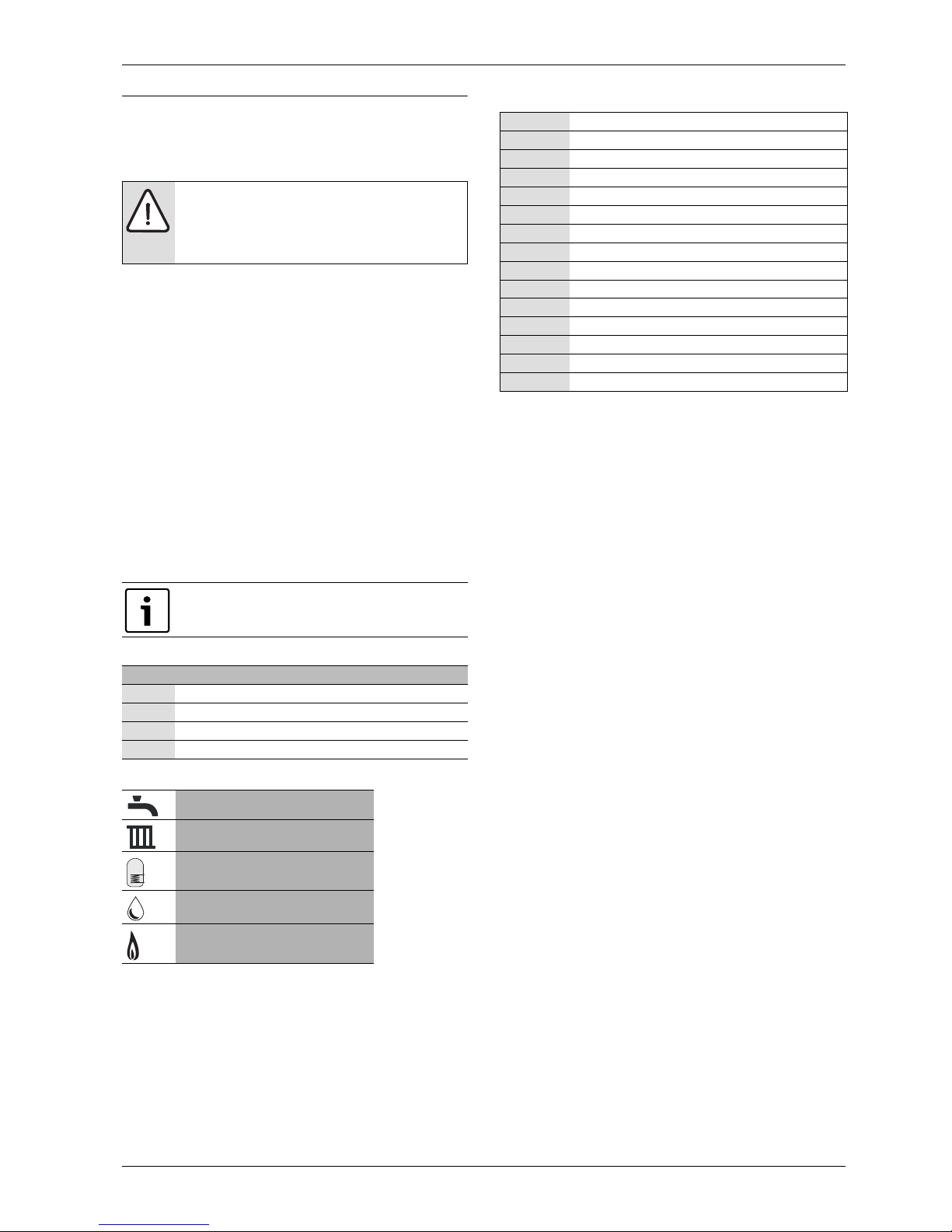
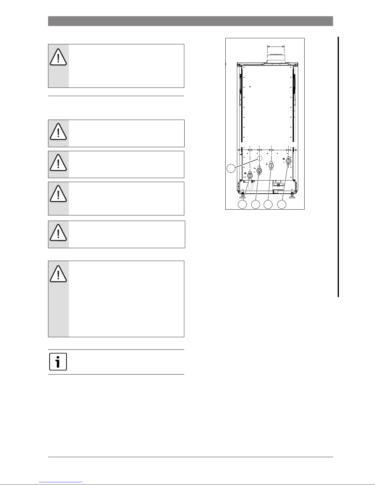
2.6 Dimensions and description
Fig. 2 Pipe work connector location
Regular boiler:
[1] Hot water flow (1”)
[2] Gas (3/4”)
[3*] Not used on the regular boiler
[4] Hot water return (1”)
[5] Condensate outlet
[6] 80/125 Flue outlet
System boiler:
[1] Heating and DHW flow (1”)
[2] Gas (3/4”)
[3*] DHW return (1”) (only if optional diverter valve kit is fitted)
[4] Heating return (1”)
[5] Condensate outlet
[6] 80/125 Flue outlet
1
6
2
3*
4
6720809859-10.1Wo
123*4
466
394
61
78 111
141 253
Ø80
Ø125
98
130
162
193
5
83
59
900 - 930
Page 6
6 | Appliance information
Product Name6 720 ... ... (YYYY/MM)
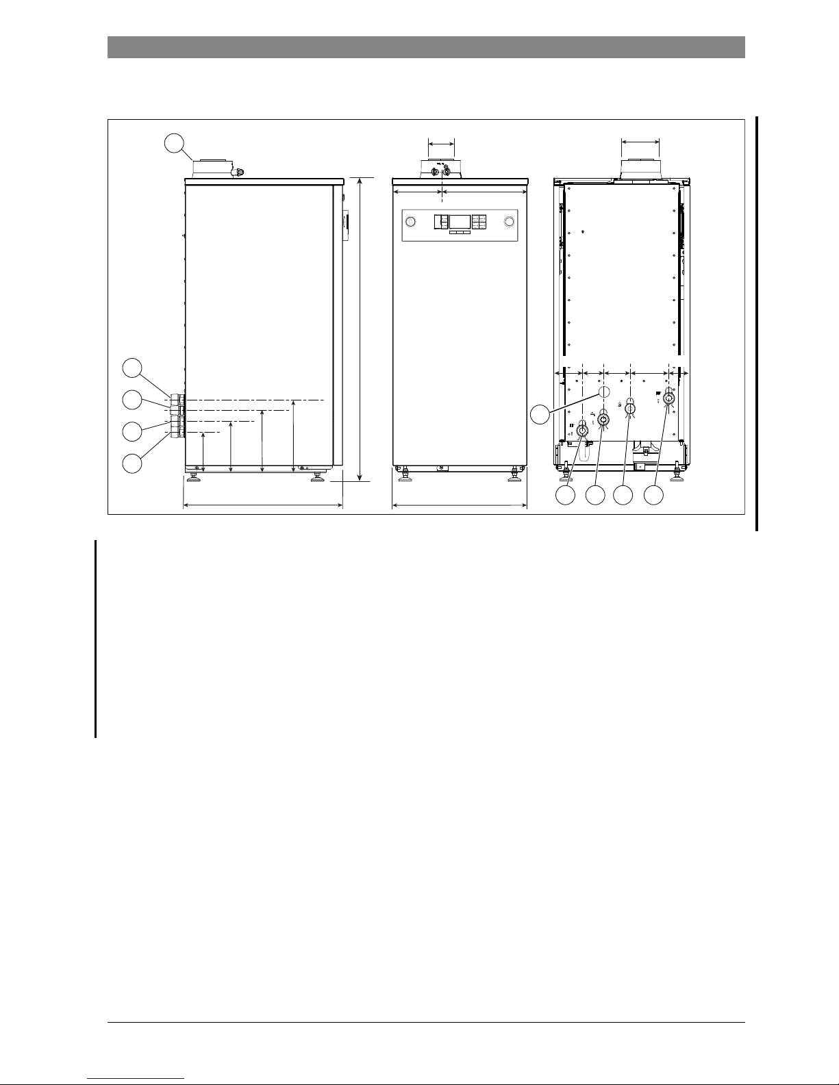
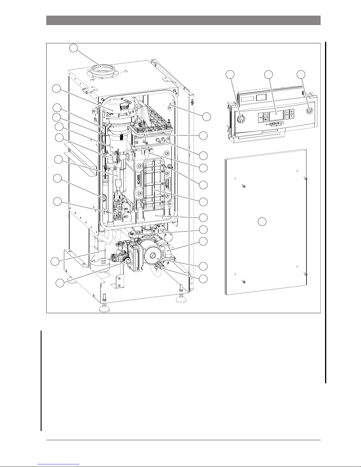
2.7 Regular boiler layout and components
Fig. 3 Component layout KBR
Legend to figure 3:
[1] Flue connector
[2] ON/OFF switch
[3] Display
[4] Pressure gauge
[5] Combustion chamber cover mounting bracket x 4
[6] Flame sense electrode
[7] Electrode assembly
[8] Flow temperature sensor
[9] High limit thermostat
[10] Heat exchanger inspection cover
[11] Condensate pan
[12] Pressure relief valve
[13] Drain cock
[14] Condensate trap
[15] Gas valve
[16] Flue overheat thermostat
[17] Air Intake pipes (30 and 42kW boilers only)
[18] Manual vent
[19] Pre-mix chamber
[20] Spark generator
[21] Fan
[22] Combustion chamber cover
2
14
16
12
10
11
15
9
8
7
6
21
5
18
20
19
43
6720809859-12.1Wo
13
17
1
22
Page 7
Appliance information | 7
6 720 ... ... (YYYY/MM)Product Name
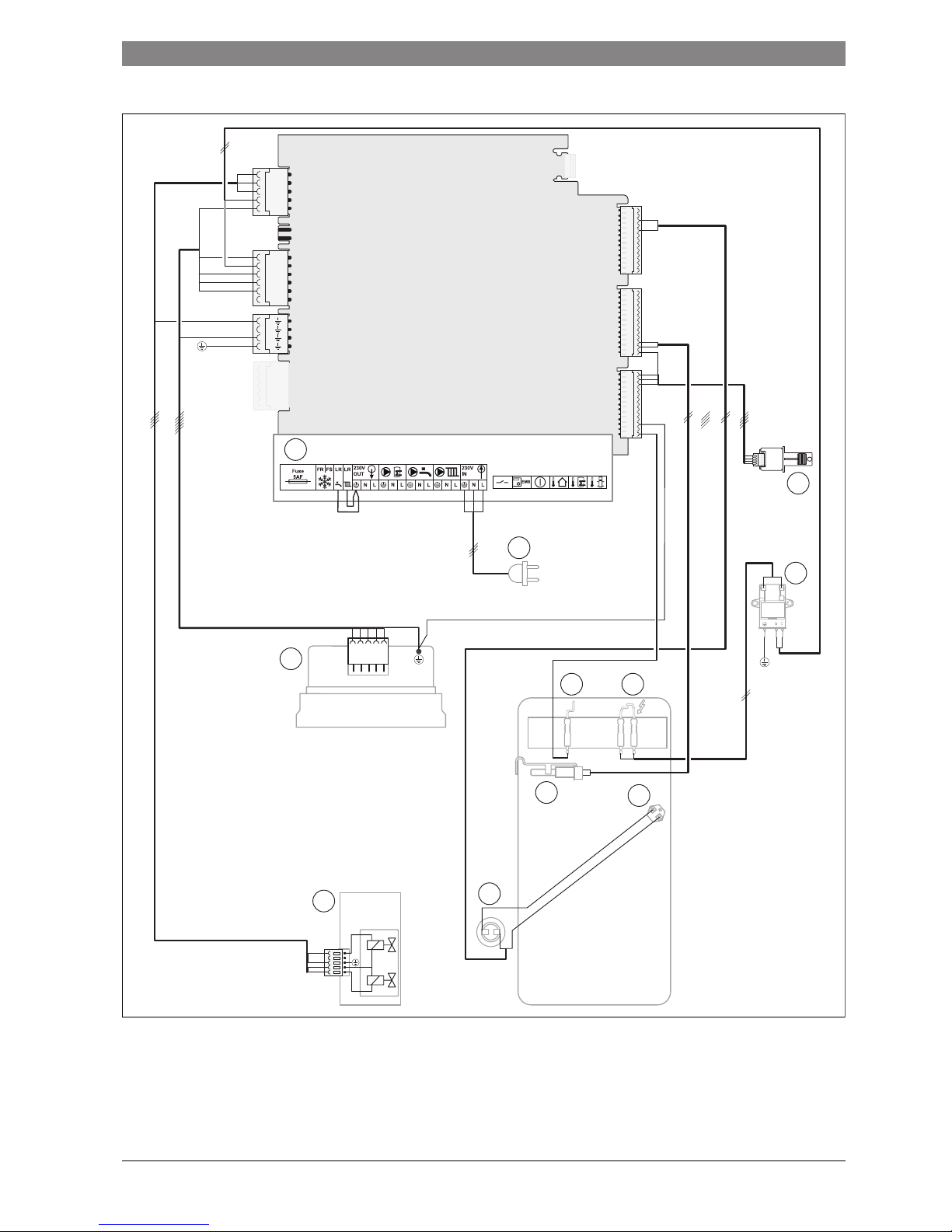
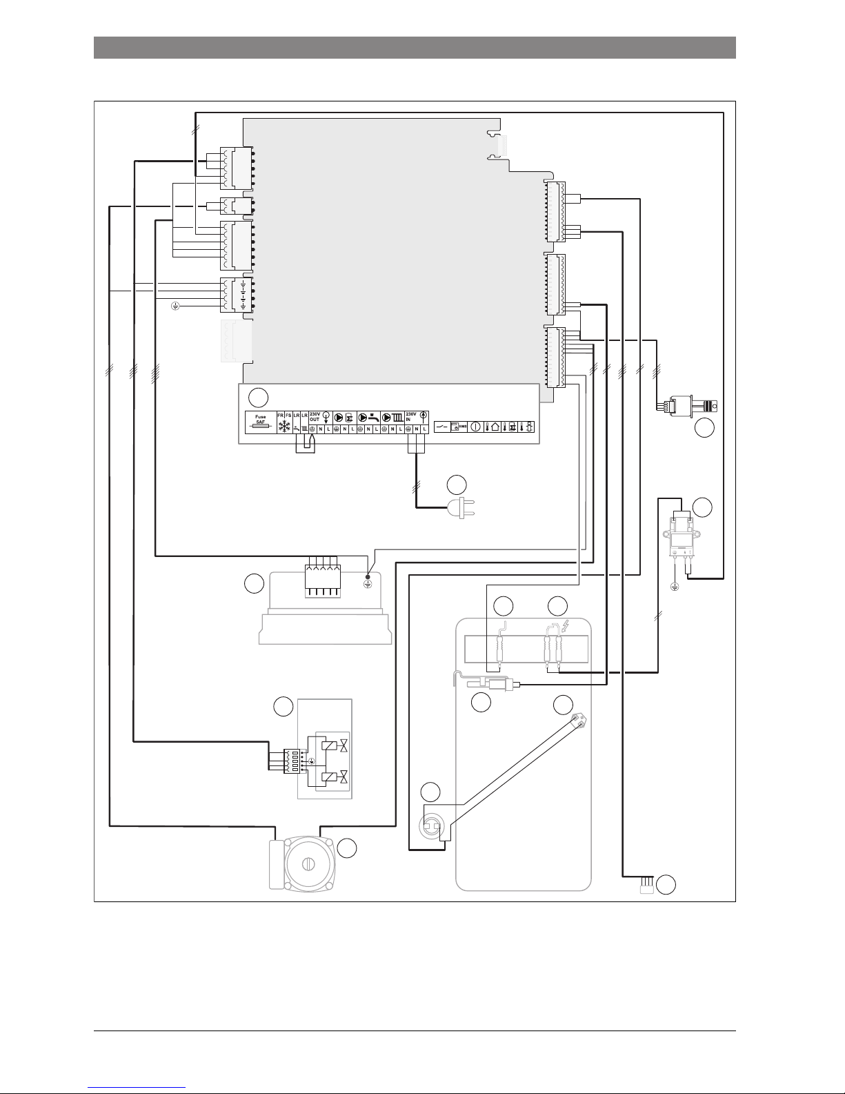
2.8 Regular boiler wiring diagram
Fig. 4
[1] Appliance terminal connector block
[2] Mains supply
[3] Heat control module (HCM)
[4] Spark generator
[5] Spark electrodes
[6] Flame sense electrode
[7] High limit thermostat
[8] Flow temperature sensor
[9] Flue overheat thermostat
[10] Gas valve
[11] Fan
L1
N
L2
N
N
1
11
3
4
2
9
7
56
8
10
6720809859-08.1Wo
Page 8
8 | Appliance information
Product Name6 720 ... ... (YYYY/MM)
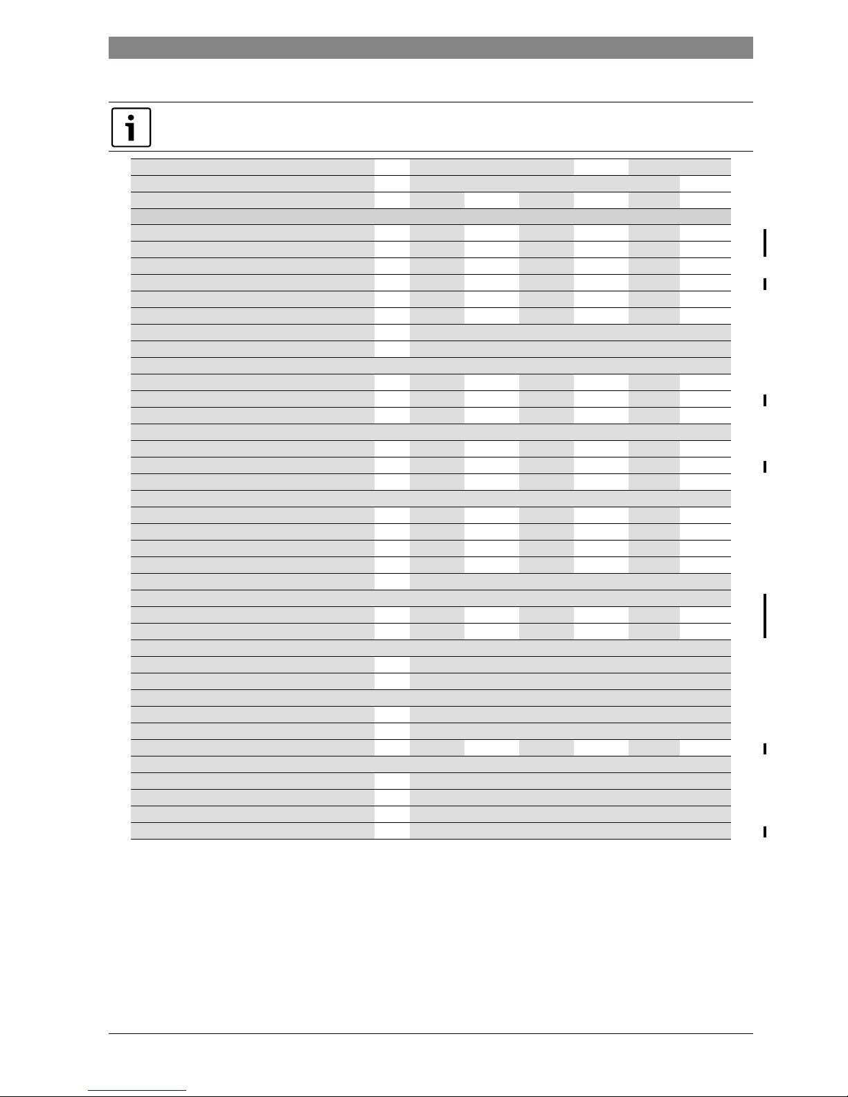
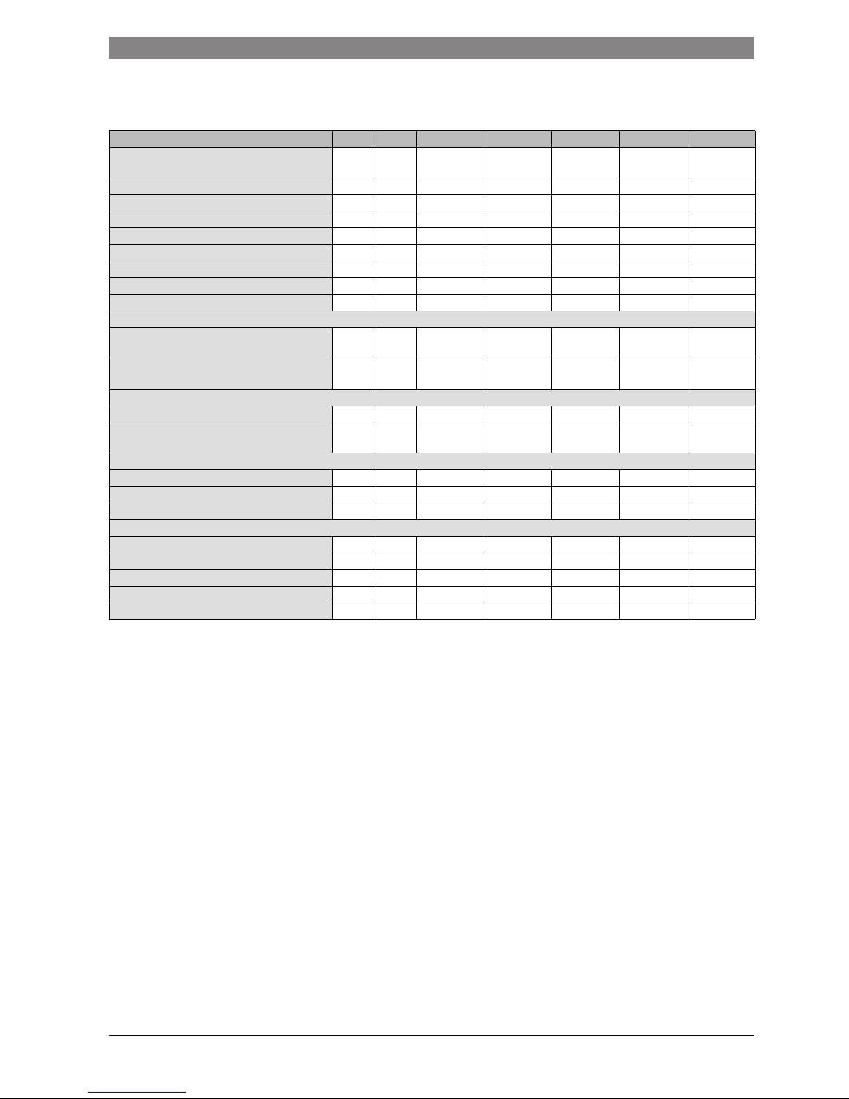
2.9 Regular boiler Technical data
All the technical data quoted in the table below refer to an appliance tested at sea level.
Power outputs are reduced due to altitude, refer to figures 5 and 6 for the percentage reduction power output due to altitude
DESCRIPTION Units Natural Gas Propane
16kW 30kW 42kW 16kW 30kW 42kW
Central Heating G20 G25 G20 G25 G20 G25 G31 G31 G31
Input/Output
Max. rated heat output net 50/30°C kW 17.00 13.90 31.70 26.00 39.80 32.60 15.80 31.70 41.00
Max. rated heat output net 80/60°C kW 15.30 12.60 30.10 24.67 38.10 31.20 14.60 30.10 38.40
Max. rated heat input net kW 16.00 13.10 30.90 25.30 39.00 32.00 16.00 30.90 39.00
Min. rated heat output net 50/30°C kW 3.80 3.10 8.00 6.60 10.10 8.30 6.40 11.52 13.50
Min. rated heat output net 80/60°C kW 3.50 2.90 7.00 5.60 9.40 7.70 5.70 10.20 12.50
Min. rated heat input net kW 3.70 3.10 8.00 6.60 10.30 8.40 6.30 10.80 13.50
Max. flow temperature °C 82
Max. permissible operating pressure bar 3.00
Gas flow rate - Max. 10 minutes from lighting
Natural Gas G20 m3/h 1.66 3.28 4.05
Natural Gas G25 m3h 1.54 3.17 3.92
Propane Gas G31 kg/h 0.61 1.27 1.65
Gas supply pressure
Natural Gas G20 mbar 20 20 20
Natural Gas G25 mbar 25 25 25
Propane Gas G31 mbar 37 37 37
Flue
Flue Gas Temp. 80/60°C, max/min °C 67/55 67/55 67/55 67/55 77/55 77/55 67/55 67/55 77/55
Flue Gas Temp. 40/30°C, max/min °C 43/25 43/25 43/25 43/25 43/25 43/25 43/25 43/22 43/25
CO2 level at max. rated heat output % 9.4 7.4 9.4 7.4 9.4 7.5 10.8 10.8 10.9
CO2 level at min. rated heat output % 8.6 6.9 8.6 6.9 9.4 7.4 10.4 10.4 10.8
NOx - classification class 555555555
Exhaust gas flow rate
Maximum g/s 6.8 6.8 13.3 13.3 17.2 17.2 6.7 12.8 16.2
Minimum g/s 1.7 1.7 3.4 3.4 4.1 4.1 2.6 6.2 7.9
Condensate
Max. condensation rate l/h 3.7
pH value, approx. 4.8
Electrical
Electrical power supply voltage AC...V 230
Frequency Hz 50
Max. power consumption (excluding external pumps) W 28 28 48 48 68 68 27 48 66
General Data
Appliance protection rating IP X4D
Permissible ambient temperatures °C -20 to +50
Nominal water capacity of appliance Itr 3.75
Weight (excluding packaging) kg 52
Table 5 Appliance technical data KBR
Page 9
Appliance information | 9
6 720 ... ... (YYYY/MM)Product Name
2.10 Gas type and installation type
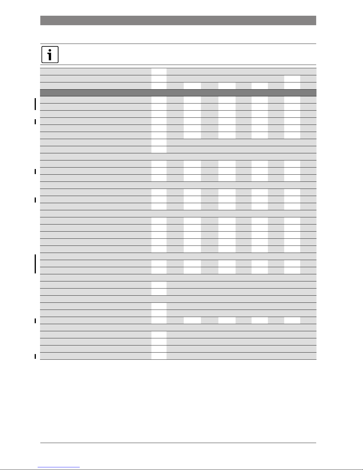
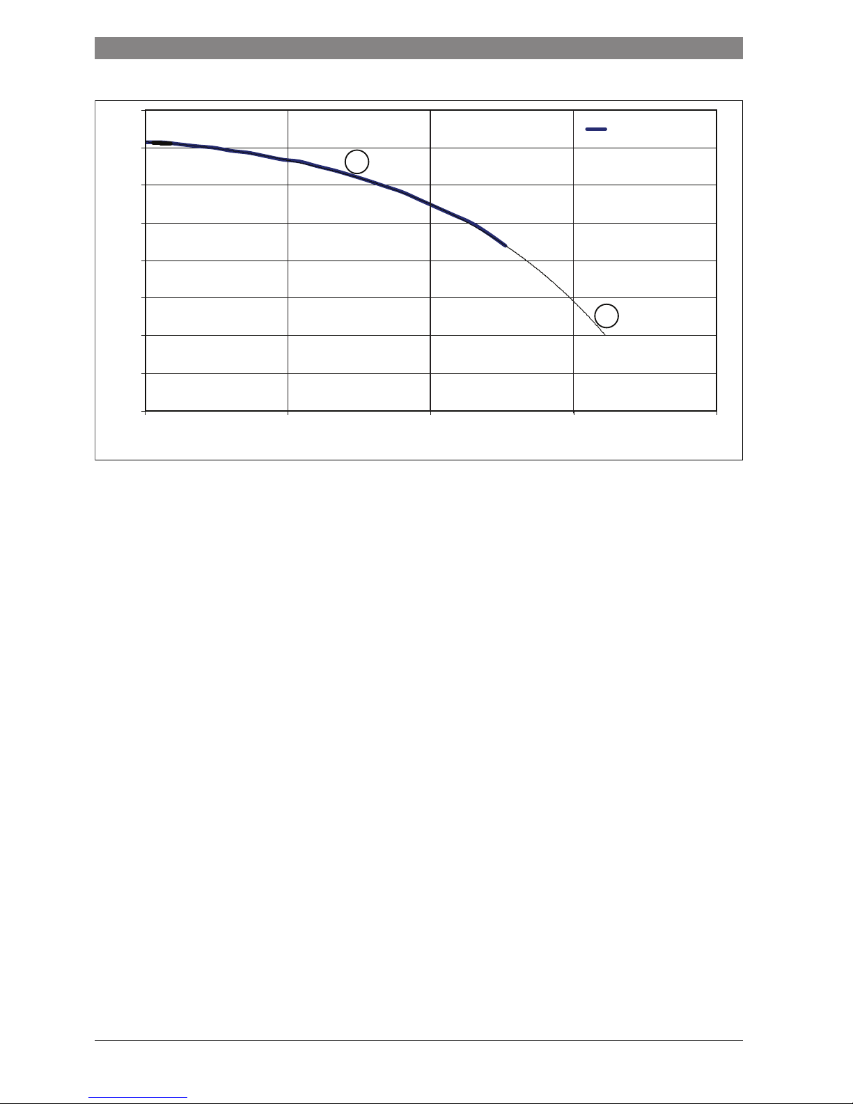
2.11 Output power reduction due to altitude
The graph in figure 5 below applies to all boiler sizes using natural gas, and the graph in figure 6 below applies to all boiler sizes using LPG.
The power output of the boilers quoted in tables 5 and 8 are reduced due to the altitude of the installation, refer to the graphs below for the percentage
output reduction.
Output power reduce on natural gas boilers due to altitude
Fig. 5 Output reduction due to altitude for natural gas
[1] Percentage output at elevation
[2] Percentage estimated output at elevation
[A] Altitude in metres
[kW(%)] Percentage kiloWatt output
Country
Rated gas pressure (mbar)
Gas
category
Factory setting (gas family,
gas group and test gas)
Factory setting rated
gas pressure (mbar)
Installation typeNatural gas LPG
Austria AT 20 50 Cat II
2H 3P
G20 20 B
23, B23P, B33, C13X,
C
33X, C43X, C53X, C63X,
C
83X, C93X
France FR 20 37 Cat II
2E SI 3P
G20 20
Italy IT 20 37 Cat II
2H 3B/P
G20 20
Czech Republic CZ 20 37 Cat II
2H 3B/P
G20 20
Russia RU 13 37 Cat II
2H 3B/P
G20 20
Poland PO 20 37 Cat II
2H 3P
G20 20
Belgium BE 20/25 Cat II
2E
G20/25 20 B
23, B33, C13X, C33X,
C
43X, C53X, C83X, C93X
Belgium BE 37 Cat II
3P
G31 37
Table 6 Gas type and installations per country
Wobbe index (WS) (15C) gas group Gas group
12.5 to 15.2 kWh/m
3
Natural gas 2H
11.4 to 15.2 kWh/m
3
Natural gas 2E
9.5 to 12.5 kWh/m
3
Natural gas 2LL
20.2 to 24.3 kWh/m
3
LPG 3B/P
20.2 to 21.4 kWh/m
3
LPG 3P
Table 7 Test gas disclosures with code and gas group (EN437)
75%
80%
85%
90%
95%
100%
0 250 500 750 1000 1250 1500 1750 2000 2250 2500 2750 3000
kW (%)
A (Metres)
1
2
6720809859-75.1Wo
Page 10
10 | Appliance information
Product Name6 720 ... ... (YYYY/MM)
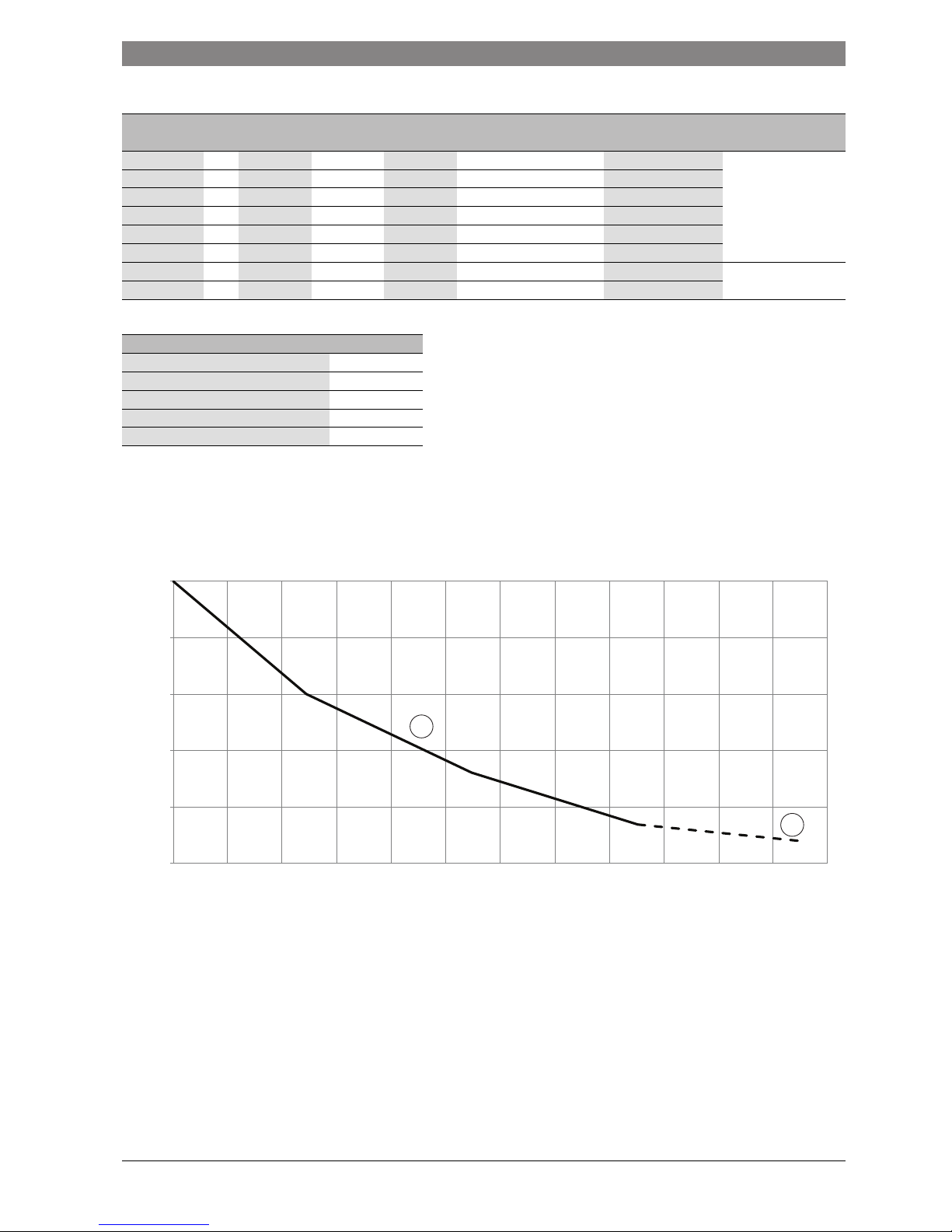
Output power reduce on LPG boilers due to altitude
Fig. 6 Output reduction due to altitude for LPG
Pressure loss in the system versus system flow
Fig. 7
[p( mbar)]Pressure loss in millibars
[F (litres/h)]Re-circulated quantity of water in litres per hour
75%
80%
85%
90%
95%
100%
0 250 500 750 1000 1250 1500 1750 2000 2250 2500 2750 3000
kW (%)
A (Metres)
1
2
6720809859-76.1Wo
0
50
100
150
200
250
300
350
400
450
500
550
600
0 300 600 900 1200 1500 1800 2100
P (mbar)
F (litres/h)
6720809859-88.1Wo
Page 11
Appliance information | 11
6 720 ... ... (YYYY/MM)Product Name
2.12 System boiler layout and components
Fig. 8 Component layout KSBR
Legend to figure 5:
[1] Flue connector
[2] ON/OFF switch
[3] Display
[4] Pressure gauge
[5] Combustion chamber cover mounting bracket x 4
[6] Flame sense electrode
[7] Electrode assembly
[8] Flow temperature sensor
[9] High limit thermostat
[10] Heat exchanger inspection cover
[11] Condensate pan
[12] Auto air vent
[13] Diverter valve assembly (only with option accessory kit)
[14] Pump
[15] Drain cock
[16] Pressure relief valve
[17] Condensate trap
[18] Gas valve
[19] Flue overheat thermostat
[20] Air Intake pipes (30 and 42kW boilers only)
[21] Manual vent
[22] Mixing device
[23] Spark generator
[24] Flue exhaust
[25] Fan
[26] Combustion chamber cover
20
1
2
19
15
14
13
12
10
11
18
17
16
9
8
7
6
25
5
24
22
23
21
43
6720809859-11.1Wo
26
Page 12
12 | Appliance information
Product Name6 720 ... ... (YYYY/MM)
2.13 System boiler wiring diagram
Fig. 9
[1] Appliance terminal connector block
[2] Mains electrical supply connector
[3] Heat control module (HCM)
[4] Spark generator
[5] Spark electrodes
[6] Flame sense electrode
[7] High limit thermostat
[8] Flow temperature sensor
[9] Diverter valve connection
[10] Pump
[11] Flue overheat thermostat
[12] Gas valve
[13] Fan
L1
N
L2
N
N
1
13
9
3
4
2
11
7
56
8
6720809859-07.1Wo
12
10
Page 13
Appliance information | 13
6 720 ... ... (YYYY/MM)Product Name
2.14 System boiler Technical data
All the technical data quoted in the table below refer to an appliance tested at sea level.
Power outputs are reduced due to altitude, refer to figures 5 and 6 for the percentage reduction in power output due to altitude
DESCRIPTION Units Natural Gas Propane
16kW 30kW 16kW 30kW
Central Heating G20 G25 G20 G25 G31 G31
Input/Output
Max. rated heat output net 50/30°C kW 17.00 13.90 31.70 26.00 15.80 31.70
Max. rated heat output net 80/60°C kW 15.30 12.60 30.10 24.67 14.60 30.10
Max. rated heat input net kW 16.00 13.10 30.90 25.30 16.00 30.90
Min. rated heat output net 50/30°C kW 3.80 3.10 8.00 6.60 6.40 11.52
Min. rated heat output net 80/60°C kW 3.50 2.90 7.00 5.60 5.70 10.20
Min. rated heat input net kW 3.70 3.10 8.00 6.60 6.30 10.80
Max. flow temperature °C 82
Max. permissible operating pressure bar 3.00
Gas flow rate - Max. 10 minutes from lighting
Natural Gas G20 m3/h 1.66 3.28
Natural Gas G25 m3/h 1.54 3.17
Propane Gas G31 kg/h 0.61 1.27
Gas supply pressure
Natural Gas G20 mbar 20 20
Natural Gas G25 mbar 25 25
Propane Gas G31 mbar 37 37
Flue
Flue Gas Temp. 80/60°C, max/min °C 67/55 67/55 67/55 67/55 67/55 67/55
Flue Gas Temp. 40/30°C, max/min °C 43/25 43/25 43/25 43/25 43/25 43/25
CO2 level at max. rated heat output % 9.4 7.4 9.4 7.4 10.8 10.8
CO2 level at min. rated heat output % 8.6 6.9 8.6 6.9 10.4 10.4
NOx - classification class 5
Exhaust gas flow rate
Maximum g/s 6.8 6.8 13.3 13.3 6.7 12.8
Minimum g/s 1.7 1.7 3.4 3.4 2.6 6.2
Condensate
Max. condensation rate l/h 3.7
pH value, approx. 4.8
Electrical
Electrical power supply voltage AC...V 230
Frequency Hz 50
Max. power consumption (including pump) W 97 97 116 116 95 116
General Data
Appliance protection rating IP X4D
Permissible ambient temperatures °C -20 to +50
Nominal water capacity of appliance Itr 3.75
Weight (excluding packaging) kg 54
Table 8 Appliance technical data KSBR
Page 14
14 | Appliance information
Product Name6 720 ... ... (YYYY/MM)
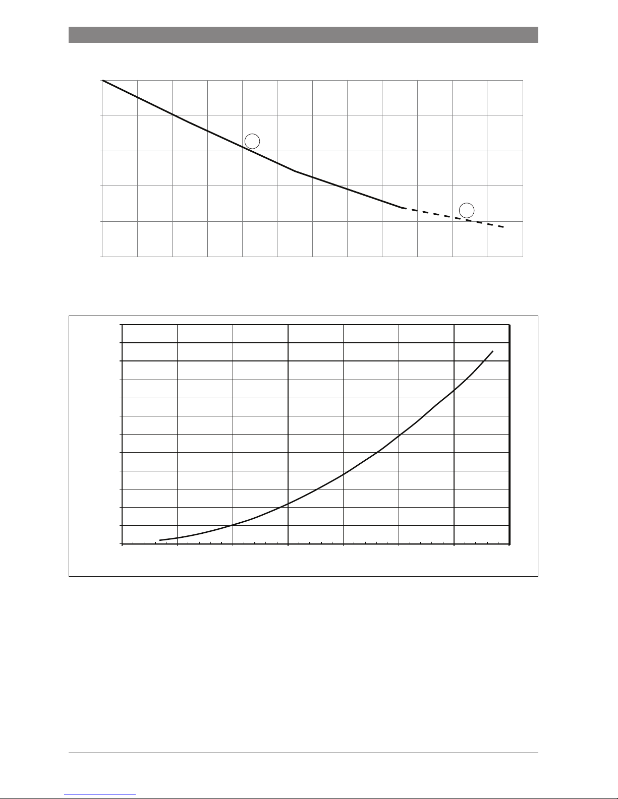
Pumphead versus Flow rate
Fig. 10
[APH] Available pump head
[FR] Flow rate
[1] Actual data
[2] Extrapolated data
0
1
2
3
4
5
6
7
8
0 500 1000 1500 2000
6720809859-87.1Wo
1
2
APH ( m wg)
FR (l/hr)
Pump (m wg)
Page 15
Appliance information | 15
6 720 ... ... (YYYY/MM)Product Name
2.15 Energy efficiency
The following product data satisfy the requirements of the EU Regulations No. 811/2013, No. 812/2013, No. 813/2013 and No. 814/2013
supplementing Directive 2010/30/EU.
Product data Symbol Unit 7731600026 7731600027 7731600028 7731600029 7713600030
Product type – – Condens
2000F 16 NG
Condens
2000F 30 NG
Condens
2000F 42 NG
Condens
3000F16 NG
Condens
3000F 30 NG
Condensing boiler – – Yes Yes Yes Yes Yes
Low temperature boiler – – No No No No No
B1 boiler – – No No No No No
Cogeneration space heater (CHP) – – No No No No No
Combination heater – – No No No No No
Rated heat output P
rated
kW 16 30.9 39 16 30.9
Seasonal space heating energy efficiency
s
% 9393929393
Energy efficiency class – – A A A A A
Useful heat output
At rated heat output and high temperature regime
1)
1) High temperature regime means 60 °C return temperature at heater inlet and 80 °C feed temperature at heater outlet.
P
4
kW 15.3 30.1 38.1 15.3 30.1
At 30 % of rated heat output and low temperature
regime
2)
2) Low temperature means for condensing boilers 30 °C, for low-temperature boilers 37 °C and for other heaters 50 °C return temperature (at heater inlet).
P
1
kW 3.5 7 9.4 3.5 7
Useful efficiency
At rated heat output & high temperature regime 1)
4
% 88.2 88.2 88.2 88.2 88.2
At 30 % of rated heat output & low temperature
regime
2)
1
% 98.9 97.6 97 98.7 97.6
Auxiliary electricity consumption
At full load el
max
kW 0.028 0.048 0.068 0.097 0.116
At part load el
min
kW 0.015 0.015 0.016 0.049 0.054
In standby mode P
SB
kW 0.0016 0.0016 0.0016 0.0016 0.0016
Other items
Standby heat loss P
stby
kW 0.059 0.059 0.059 0.076 0.076
Ignition burner power consumption P
ign
kW00000
Emissions of nitrogen oxides NOx mg/kWh 32 29 27 32 29
Annual energy consumption Q
HE
kWh - - - - Sound power level, indoors L
WA
dB(A) 47.9 54.9 52.6 47.9 52.6
Table 9 Product data for energy consumption according to the EU regulations no. 813/2013 and no. 813/2013
Page 16
16 | Regulations
Product Name6 720 ... ... (YYYY/MM)
3 Regulations
The boiler is designed to operated in conformity with the following
requirements:
• EN 677, EN 483, EN 15502
• EN 437
• Gas appliance directive 2009/142/EG
• Efficiency directive 92/42/EWG
• EMV directive 2004/108/EG
• Low voltage directive 2006/95/EG
3.1 Country specific regulations
For installation and operation, please refer to country specific standards
and regulations. Critical are:
• Local standards and regulations for siting the appliance
• Local standards and regulations for combustion air supply,
ventilation and connection to a flue gas system
• Regulations for connection to an electrical mains supply
• Regulations of the gas supplier for connecting a gas appliance onto
the local distribution network
• Standards and regulations for safety equipment on wet heating
systems
3.2 Approvals and notifications
• The installation of a gas boiler must be declared to, and approved by
the gas supplier.
• Please note, local regulations may require third party approval when
connecting to a flue gas system or drain condensate into the local
sewage system
• Where required, inform local representative (i.e. chimney sweeper)
before installing the boiler
3.3 Quality of the heating water
Use water to drinking water quality when filling and toping up the heating
system.
Unsuitable or contaminated water can lead to problems or damage of the
heat exchanger and water supply caused by i.e. sludge, corrosion and
scale build up.
Apply the following steps:
▶ Thoroughly flush the system before filling
▶ Water from wells and springs are not suitable as fill water
▶ Consider the total volume of scale introduced into the heating system
over its lifetime, by fill and top up water, and protect it against
damage with that in mind
▶ For systems with a volume 50litres/kW (i.e. when using buffer
vessels) the water must be treated. An approved solution is the full
removal of salts from the fill and top up water, achieving a
conductivity of 10
μsiemens/cm (= 10μS/cm).
Instead of a the water treatment solution you could install a means of
system separation (i.e. plate heat exchanger) directly after the
boiler.
▶ Please contact the manufacturer of the appliance for additional
inhibitors and anti freezes. Always refer to the manufacturer's advice
for filling and continuous maintenance when using these solutions.
3.4 Connection to combustion air and flue gas systems
• Always refer to the latest version of the applicable local standards
and regulations
• Further information about combustion air supply and connection to
flue gas systems can be found in chapter 5 in this manual.
• Also refer to the documentation supplied with the flue gas system.
3.5 Room air dependent operation
The boiler primarily operates as a “room air sealed” unit, however the
boiler can be operated as a “room air dependant” unit, if required.
Provide sufficient boiler room ventilation when operating the appliance
room air dependent
▶ Do not obstruct or block any ventilation openings
▶ Ventilation openings must always be kept clear
3.6 Flue gas systems type B
xx
Type B flue gas systems take combustion air from the boiler room. Flue
gas exits the appliance via the flue gas system. Special regulations apply
for installations of this type - comply with these requirements. Sufficient
combustion air must be available.
3.7 Flue gas systems type C
xx
Type C flue gas systems take combustion air from outside the building.
Flue gas exits the appliance via the flue gas system to the outside. To
ensure this, the combustion chamber door is air tight. Therefore always
ensure the combustion chamber door is closed when operating the
appliance room air sealed.
• Refer to the installation instructions of the flue gas system when
installing the appliance
3.8 Combustion air quality
To avoid corrosion, combustion air must be free from aggressive
substances (hydrogen halide, chlorines and fluorine).
3.9 Disposal
• Dispose any part of the heating system via an authorised facility
3.10 Inspection, service and maintenance
The heating system should be service regularly for the following reasons:
• To achieve and maintain a high efficiency and low fuel consumption
• To ensure operational safety
• To keep combustion clean and emissions low
Water quality is an important factor to increase the
efficiency, safety, reliability and availability of your
heating system.
DANGER: Risk to life from flue gas poisoning.
Insufficient combustion air supply can lead to flue gas
escaping.
▶ Ensure combustion air supply
▶ Supply and extract vents in doors, windows and
walls must not be closed off or reduced in size.
▶ Ensure a sufficient combustion air supply, also with
equipment installed afterwards: i.e. kitchen extract
fans and air conditioning units extracting air to the
outside
▶ Do not operate the appliance if combustion air
supply is insufficient.
NOTICE: Damage to boiler from contaminated
combustion air and contaminated air in the vicinity of
the appliance!
▶ Never operate the boiler in an dusty and chemically
aggressive environment i.e. spray painting, hair
dressing and farming facilities
▶ Never operate the boiler in places where using or
storing trichlorethane, hydrogen halide and other
aggressive chemical substances. These substances
can be contained in spray cans, various glues,
primers, paints and cleaning substances. In this case
always install the appliance room air sealed in a
hermetically sealed plant room with ventilation
directly to the outside.
Page 17
Pre-installation | 17
6 720 ... ... (YYYY/MM)Product Name
Service interval
4 Pre-installation
4.1 Cleaning primary systems
4.2 Hydraulic connections
4.2.1 Connecting flow and return
Fig. 11 Pipe work connector location
Regular boiler:
[1] Hot water flow (1”)
[2] Gas (3/4”)
[3*] Not use on the Regular boiler
[4] Hot water return (1”)
[5] Condensate outlet
System boiler:
[1] Heating and DHW flow (1”)
[2] Gas (3/4”)
[3*] DHW return (1”) (only if optional diverter valve kit is fitted)
[4] Heating return (1”)
[5] Condensate outlet
NOTICE: Damage to the system caused by a lack of or
insufficient cleaning and servicing.
▶ Get the heating system inspected at least annually by
an authorised heating engineer
▶ Carry out a service as required. Carry out any repairs
immediately to avoid any damage to the system
NOTICE: Before installation
▶ All the following Pre-Installation sections must be
read and requirements met before starting boiler or
flue installations.
CAUTION: MAINS POWER
▶ ISOLATE THE MAINS SUPPLIES BEFORE STARTING
ANY WORK AND OBSERVE ALL RELEVANT SAFETY
PRECAUTIONS.
NOTICE: Protect the boiler
▶ Debris from the system can damage the boiler and
reduce efficiency.Failure to comply with guidelines
for the use of water treatment with the appliance will
invalidate the appliance warranty.
WARNING: Sealing agents
▶ The addition of sealing agents to the system water is
not permitted, this can cause problems with deposits
left in the heat exchanger.
NOTICE: Damage to property caused by leaking
connections:
▶ Ensure the pipes are installed without mechanical
strain onto the appliance connections
▶ Refurbish seals when loosening or removing
connection joints
▶ Check gaskets and connections for signs of damage
▶ We recommend the installation of a line strainer in
the system return to protect the heating system
▶ Fit isolating valves before and after the line strainer
to allow for servicing
Fit isolation valves in the flow and return to allow
servicing of the appliance
6720809859-10.1Wo
123*4
61
78 111
Ø125
5
83
59
Page 18

18 | Pre-installation
Product Name6 720 ... ... (YYYY/MM)
4.2.2 Expansion vessel and drain valve
Connect an expansion vessel
EN12828 requires and expansion vessel to be installed with the boiler.
▶ Install an expansion vessel in the return to the pump
Fill and drain connections
EN1717 requires a filling of the heating system with drinking water only
via a fixed connection between water supply and heating circuit.
▶ Fit an external filling link between the DCW and CH Flow on the
appliance
4.3 Water systems and pipework
Primary system plastic pipework
• Any plastic pipe work must have a polymeric barrier with 600mm
(minimum) length of copper connected to the boiler.
• Plastic pipe work used for under floor heating must be correctly
controlled with a thermostatic blending valve limiting the
temperature of the circuits to approximately 50°C. The pipe work
from the boiler to the blending valve must be in copper.
Primary system/connections/valves:
• Do not use galvanised pipes or radiators.
• All system connections, taps and mixing valves must be capable of
sustaining a pressure of 3 bar.
• Drain cocks are required at all the lowest points on the system.
• Air vents are required at all high points on the system.
4.4 Condensate drain
Ensure that the condensate trap has at least 250ml of clean water in it
before the boiler is run.
If the flue has not been fitted yet, the water can be poured down the inner
flue pipe. If the flue has already been fitted, the condensate trap will
have to be removed and filled.
4.4.1 To remove the condensate trap
▶ Release the hose clamp [1]
▶ Remove the screw retaining the trap [2]
▶ Pull the trap down to remove the trap from boiler
▶ Pour 250ml of clean water into the top of the trap
▶ Re-fit the trap to the boiler
Fig. 12 Condensate trap
▶ Install condensate neutralisation systems (optional accessory) in line
with the installation instructions
▶ Ensure that the condensate pipework leading away from the
appliance falls away towards the drainage point
▶ Connect into the sewage system based on national and local
standards and regulations
4.5 Boiler location and clearances
4.5.1 Installation
• This boiler is only suitable for installing internally within a property at
a suitable location onto a fixed rigid non-combustible surface at least
the same size as the boiler and capable of supporting the boiler
weight.
• The boiler is not suitable for external installation unless a suitable
enclosure is provided.
4.5.2 Installations and servicing clearances:
The dimensions below are the minimum space required to install,
service and perform maintenance on the boiler only.
Fig. 13 Installation clearances
[1] 1900mm
[2] 2500mm
[3] 2000mm
[4] 70mm
DANGER: Danger to life by poisoning from escaping flue
gas. Flue gas can escape if condensate trap is not filled
with water or connections are not sealing properly.
▶ Fill the siphon with water
NOTICE: Additional advice on draining condensate
▶ Any condensate in the appliance and the flue gas
system must be drained in an appropriate manner
(flue gas system must have sufficient fall towards the
appliance)
▶ Comply with country specific standards and
regulations when connecting the condensate into the
sewage system
▶ Comply with local regulations
Condensate neutralisation systems are available as an
accessory.
6720809859-77.1Wo
2
1
6720809859-09.1Wo
1
2
3
4
Page 19
INSTALLATION | 19
6 720 ... ... (YYYY/MM)Product Name
5 INSTALLATION
5.1 Unpacking the boiler
Unpacking:
1. Undo the ties securing the carton
If a sharp implement is used, care must be taken not to pierce the
carton or cause injury.
2. Before removing the carton it is advised that the top flaps are opened
and the ancillary items (A, B, & C) are removed and set to one side.
3. The carton can now be lifted off the boiler.
▶ Remove the plastic bag protecting the boiler surfaces and place
safely away from the working area.
General handling guidelines:
▶ Lift only a manageable weight, or ask for help.
▶ When lifting, bend the knees, and keep the back straight and feet
apart.
▶ Do not lift and twist at the same time. Lift and carry items close to the
body
▶ Wear protective clothing and gloves to protect from any sharp edges
Fig. 14 Unpacking
[A] Literature pack
[B] PRV disposal pipe
[C] Levelling feet x4
5.2 Boiler room requirements
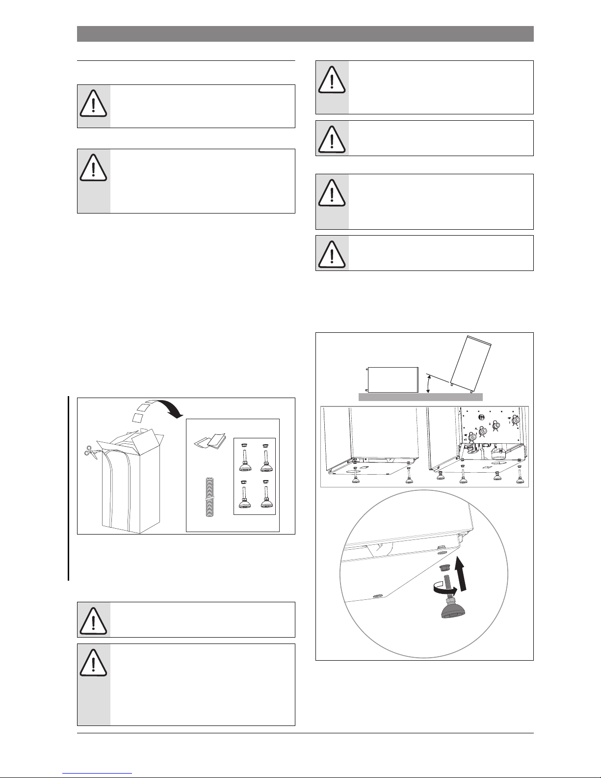
5.2.1 Installing the levelling feet
▶ Screw a levelling nut onto the threaded shaft of each of the feet
▶ Screw the threaded shaft into the base of the boiler at each corner as
indicated in figure 15
▶ Adjust the feet to be approximately the same length
▶ Level the boiler as described in section 5.2.2
Fig. 15 Fitting the feet
NOTICE: Boiler start up
▶ All the previous Pre-Installation sections must be
read and requirements met before starting boiler or
flue installation.
NOTICE: Boiler handling
▶ At all times the correct method for handling heavy
objects should be strictly observed.
▶ Take care not to damage the boiler panels or floor.
▶ The boiler may contain water due to factory testing
▶ Store the boiler in a dry area prior to installation
DANGER: Explosive and flammable materials
▶ Do not store flammable materials (paper, curtains,
clothing, primer, paint, …) in proximity to the boiler
NOTICE: Damage to the appliance from contaminated
combustion air
▶ Do not use any cleaners containing chlorine or
hydrogen halide (i.e. spray cans, primers, cleaners,
paint and glue)
▶ Don’t store or use these substances in the boiler
room
▶ Avoid the build up of dust
1
2
6720809859-94.1Wo
A
B
C
NOTICE: Damage from overheating.
Excessive ambient temperatures may cause damage to
the heating system.
▶ Ensure the ambient temperature is above 0 °C and
below 35 °C
NOTICE: Frost damage to the appliance
▶ Fit the boiler in a frost free room
CAUTION: Toppling hazard
Boiler will topple over if tilted passed 45 °
▶ Tilt the boiler to no more than 40 °
▶ Take care when tilting the boiler to fit levelling feet,
ideally two people are required to safely fit the feet.
NOTICE: Damage to boiler
▶ Do not lie the boiler down to fit the levelling feet
x4
6720809850-95.1Wo
<40
o
Page 20

20 | INSTALLATION
Product Name6 720 ... ... (YYYY/MM)
5.2.2 Positioning the appliance
The boiler must be adjusted to be level. This ensures air can escape from
the heat exchanger and condensate drains freely.
▶ Place boiler in its final location
▶ Release the locknuts on the boiler feet
▶ Adjust the boiler feet until the boiler is level vertically and
horizontally, check using a spirit level
▶ Secure in position with the locknuts
Fig. 16 Levelling the boiler
5.3 Mounting the boiler and flue opening
Safety
All relevant safety precautions must be undertaken. Protective clothing,
footwear, gloves and safety goggles must be worn as appropriate.
Running pipes behind the boiler
• The boiler should sit at least 70mm from the rear wall to allow enough
room for access to the pipe work.
• Do not cross a pipe over another.
Fig. 17 Pipe Connections
System boiler:
[1] Heating and DHW flow (1”)
[2] Gas (3/4”)
[3*] System boiler - DHW return (1”)
(only if optional diverter valve kit is fitted)
Regular boiler - Not used
[4] Heating return (1”)
[5] Condensate outlet
NOTICE: Damage caused by insufficient load bearing or
unsuitability of the boiler room floor
▶ Ensure the floor area is suitable for installing a boiler
and can take the “wet weight” of the appliance.
NOTICE: Damaged caused by mechanical strain on the
hydraulic and flue gas connections when adjusting the
position of the appliance.
▶ Do not apply any strain the connections when
adjusting the boiler position
CAUTION: Isolate the mains gas supply before starting
any work and follow all relevant safety precautions.
6720809859-79.1Wo
6720809859-48.1Wo
394
Ø80
Ø125
1
2
3*
4
466
98
130
162
193
900 - 930
C
82
C
L
1
2
3*
4
5
61
78 111
83
59
141253
L
Page 21

INSTALLATION | 21
6 720 ... ... (YYYY/MM)Product Name
Gas connections
Flue opening
5.4 Flue options
Fig. 18 Flue options
DANGER: Risk to life from explosion of flammable gases
▶ Work on components in contact with gas must only
be carried out by a competent and authorised
person.
▶ Comply with national and local standards and
regulations
▶ Only use approved methods of making gas tight
connections
Surplus water may be present due to factory testing.
Any horizontal flue sections must rise away from the
boiler by 52mm per metre to ensure that condensate
flows back into the boiler for safe discharge via the
condensate waste pipe.
CAUTION: Non accessible flue systems:
▶ Where a flue system is not going to be accessible,
provision must be made for service and inspection.
▶ Voids containing concealed flues must have at least
one inspection hatch no less than 300mm square.
▶ Flue joints within the void must not be more than 1.5
metres from the edge of the inspection hatch.
▶ Inspection hatches should be located at changes of
direction.
▶ If this is not possible, bends should be viewable from
both directions.
NOTICE: Effective flue lengths:
▶ each 90 ° bend used is equivalent to 2.0 metres of
straight flue
▶ each 45 ° bend used is equivalent to 1.0 metre of
straight flue
Maximum total
flue length L (mm)
Flue type
1 High level horizontal flue 11 000
2 High level horizontal flue with 2 x 90 ° bends 9 000
3 High level horizontal flue with 3 x 90 ° bends 7 000
4 Vertical balanced flue assembly 15 000
5 Vertical balanced flue with 2 x 90 ° bends 11 000
6 Vertical balanced flue with 2 x 45 ° bends 13 000
Table 10 Flue options
3
L
120 mm
120 mm
1
L
120 mm
2
L
6720809859-82.1Wo
Flat roof
300 mm
500 mm
Pitched
roof
4
L
5
L
6
L
120 mm
120 mm
Page 22

22 | INSTALLATION
Product Name6 720 ... ... (YYYY/MM)
5.5 Vertical flues
Room sealed flues C33 and C93
Fig. 19 C33 RSF flue
Fig. 20 C93 RSF flue
L
1
Ø110
Ø 80
Ø 80/125
6720809859-83.1Wo
A
C33
> 1m
L
Boiler
output
(kW)
L max
(metres)
L1 max
(metres)
Equivalent
length 93 ° flue
elbow (metres)
Equivalent length
15 ° and 45 ° flue
elbow (metres)
16 13 3 2 1
30 13 3 2 1
42 13 3 2 1
Table 11
L
1
Ø 80
L
Ø 80/125
A
6720809859-84.1Wo
> 1m
C93
L
Page 23

INSTALLATION | 23
6 720 ... ... (YYYY/MM)Product Name
Open flues B33
Fig. 21 Rigid B33 flue Fig. 22 Flexible B33 flue
L
1
Ø 80
A
Ø 80/125
> 1m
6720809859-85.1Wo
L
B33
Boiler
output
(kW)
L max
(metres)
L1 max
(metres)
Equivalent
length 93 ° flue
elbow (metres)
Equivalent length
15 ° and 45 ° flue
elbow (metres)
16 13 3 2 1
30 13 3 2 1
42 13 3 2 1
Table 12
Ø 80/125
A
Ø 80
6720809859-86.1Wo
L
1
L
> 1m
B33
Page 24

24 | ELECTRICAL
Product Name6 720 ... ... (YYYY/MM)
6 ELECTRICAL
6.1 Electrical
Access to the electrical connections:
Remove the boiler front panel to gain access to electrical connections.
▶ Pull the top corners of the front panel away from the case until the
ball catches are released.
▶ Lift the panel off the lower brackets and set the panel safely aside.
Fig. 23 Electrical connections access
Access to electrical connections:
▶ Access to all wiring connections are via the Installer access cover at
the bottom front of the control panel. No access is required to other
parts of the control board.
▶ Release the three screws in the connections cover and remove the
cover.
Fig. 24
[1] Mains voltage connections
[2] Low voltage connections
[3] Cable retainers
Fig. 25 Mains voltage connections
Fig. 26 Low voltage connections
DANGER: Risk of fire from hot boiler components.
Hot boiler components can damage electrical cables.
▶ Ensure all electrical cables are in the correct cable
guides and away from hot boiler components
Run power cables separately from signal cables.
Interference from power cables can induce spurious
faults on signal cables, ensure that there is at least
300mm separation from each other.
CAUTION: ISOLATE THE MAINS ELECTRICITY SUPPLY
BEFORE STARTING ANY WORK AND OBSERVE ALL
RELEVANT SAFETY PRECAUTIONS
▶ All electrical work must be carried out by a competent
and authorised person.
▶ All work must be in line with country specific and local
standard and regulations.
▶ The isolator must have contact separation of 3mm
minimum between poles. Any system connected to
the boiler must not have a separate electrical supply.
▶ External fuse 3 Amps.
▶ When stripping the wires ensure copper strands do
not fall into the control box.
6720809859-18.1Wo
Mains voltage terminal strip
1 External frost thermostat
2 230 V A.C. switched live inputs
3 230 V A.C. mains output
4 DHW charge pump
5 DHW circulation pump
6 CH circulation pump
7 Boiler 230 V A.C. mains supply
Table 13 Key to figure 25
Low voltage terminal strip
8 Input for external demand
9 EMS bus connections
10 External cut off switch (supplied with factory fitted link)
11 Outside sensor
12 DHW cylinder sensor
13 Low Loss Header sensor
Table 14 Key to figure 26
6720809859-16.1Wo
1
3
2
6720809859-15.1Wo
230V
IN
230V
OUT
FRFSLR
LR
LN
L
N
LN
LN
LN
1
2
3 4
5
6
7
6720809859-14.1Wo
EMS
8
9
10
11
12
13
Page 25

COMMISSIONING | 25
6 720 ... ... (YYYY/MM)Product Name
Cable retainer clamps
▶ Unclip the cable clamp [1}.
▶ Cut off the tapered cable entry [2] to suit the cable diameter.
Fig. 27 Cable entry
▶ Unscrew the cable retaining screw [3}.
Run the cable [4] through the cable clamp ensuring there is ample
cable to reach the connectors.
▶ Tighten the cable retaining screw [3] to secure the cable and replace
clamp into the control panel.
Fig. 28 Cable retainers
7 COMMISSIONING
7.1 Pre-Commissioning checks
1. Check that the service and water pipes are connected to the correct
points on the back of the boiler;
1 - CH flow (1”)
2 - Gas inlet (3/4”)
3* - DHW return (1”) System boiler with optional diverter valve kit only
4 - CH return (1”)
5 - Condensate out
Fig. 29 Pre-commissioning checks
2. Check all system and boiler drain points are closed.
3. Check the gas type specified on the identification plate matches that
of the gas supply.
▶ Turn on the main gas supply and purge the gas supply to the boiler
ensuring that the room is well ventilated.
▶ Test the gas supply for tightness.
4. Check the flue is correctly fitted and the connections are secure.
5. Check the condensate pipe work is correctly fitted and connected.
6. Refit cover onto the bottom clips and secure with the ball catches.
7.2 Filling the system and checking for leaks
Check the heating system for leaks to avoid problems during
commissioning and operation.
• Ensure good ventilation, ensure all isolating valves in the heating
circuits and radiation temperature regulating valves are fully open
• Open all automatic air vents
4
3
3
1
2
≥ 5mm
6720809529-92.1Wo
36-40mm
26-30mm
6-8mm
6-8mm
N
L
6720809529-92.1Wo
CAUTION: ISOLATE THE MAINS SUPPLIES BEFORE
STARTING ANY WORK AND OBSERVE ALL RELEVANT
SAFETY PRECAUTIONS.
NOTICE: If the boiler is not commissioned immediately
then, after successfully completing all of the checks and
any rectification work, shut off the gas supply and
electrically isolate the boiler.
NOTICE: Damage due to the ingress of air into the
system
▶ The appliance is only suitable for installation and
operation on pumped, sealed and pressurised
heating systems in line with EN12828.
▶ Do not connect onto gravity and/or open vented
systems
CAUTION: Risk to health from contaminated drinking
water:
▶ Comply with country specific standards and
regulations for avoiding contamination of drinking
water
▶ In Europe, also comply with EN 1717
6720809859-67.1Wo
1
2
3*
4
5
Page 26

26 | COMMISSIONING
Product Name6 720 ... ... (YYYY/MM)
▶ Open all the system and radiator valves.
▶ Turn on the water main stop cock.
Sealed System
1. Monitor the pressure gauge on the control panel of the appliance
2. Slowly fill the system via the external filling link
3. Set the pressure between 1 and 1.5 bar pressure.
Fig. 30 Setting the system pressure
▶ Close the external filling valve
▶ Check the pipe work and connections for leaks and rectify as
necessary
▶ Vent all radiators, retighten when completed.
If the test pressure drops off as a result of the air bleeding:
▶ Top up with domestic cold mains water
▶ Complete pressure test based on the local requirements
Once the pressure test is completed and no leaks are present:
▶ Set correct working pressure
7.3 Water treatment
7.4 Starting the appliance
Fig. 31
[1] Main on/off switch
[2] Diagnostic port (Service engineers only)
[3] DHW button
[4] Heating button
[5] Display
[6] Minus button
[7] Plus button
[8] ok button
[9] Back button
[10] Pressure gauge
[11] Service button
[12] Reset button
[13] Summer/Winter mode button
Switching the appliance on/off:
1. Turn on the mains power supply.
▶ Turn on any external controls.
▶ Set the TRV controls to maximum.
▶ Set the clock or programmer, if fitted, to continuously ON and the
room thermostat to maximum temperature.
2. Switch on the appliance with the ON/OFF switch on the control
panel.
The display lights up and initially shows the appliance temperature.
Fig. 32 Main power switch
NOTICE: Damage to property from overpressure during
pressure tests!
Pressure, control and safety devices may be damaged
by excessive pressure.
▶ After filling the system pressure test to the release
pressure of the safety valve
NOTICE: Damage caused by cracks from thermal shock!
Cracks can occur when toping up a warm heating system
with cold mains water. The boiler could start leaking.
▶ Only fill and top up the heating system when cold
(maximum flow temperature 40 °C)
▶ Comply with the requirements for water quality
Have a fixed connection between mains water supply
and filling point in line with EN 1717. Fit the appropriate
safety device.
NOTICE: Debris from the system can damage the boiler
and reduce efficiency. Failure to comply with the
guidelines for the use of water treatment with the
appliance will invalidate the appliance warranty.
NOTICE:
▶ The quality of the system water must be checked
regularly. Please contact the appliance manufacturer
for further guidance.
▶ The addition of sealing agents to the system water is
not recommended as this can cause problems with
deposits left in the heat exchanger.
20809859-78.1Wo
1.
2.
3.
Min
1 bar
1.5 bar
Max
NOTICE: Never run the appliance when the appliance or
system is empty or unpressurised.
The condensate trap fill program starts each time the
appliance is turned on. The appliance runs at minimum
output for about 15 minutes to fill the condensate trap.
The symbol . flashes until 15 minutes of burner
operation has been completed.
10
6 94 732 8
1113 12
reset
5
1
6720809978-01.1Wo
6 720 646 606-27.1O
Page 27

COMMISSIONING | 27
6 720 ... ... (YYYY/MM)Product Name
Setting the boiler to maximum output
3. Press the / button together with the button to enter the
“Chimney sweep mode” , the display shows the current flow
temperature and flashes the percentage heat output in the
alphanumeric display. The burner symbol will be shown in the
display.
Press the + or - buttons until the required percentage output is
displayed. Set the output to 100% initially.
Fig. 33 Operating the boiler
4. If the boiler fails to light, press the reset button until the reset line of
text displays. The device goes back into operation and the flow
temperature is displayed.
5. Press the button at any time to return to normal operation.
7.5 Checking gas inlet pressure
7.5.1 Measuring the inlet pressure
▶ Remove the front panel figure 23
▶ Remove the combustion chamber cover.
The inlet pressure to the appliance must be checked using the following
procedure:
Fig. 34 Inlet test point
▶ Close gas isolation valve.
▶ Slacken the screw in the inlet pressure test point and connect a
manometer.
▶ Open gas isolation valve.
▶ Measure the pressure with the boiler running at maximum output.
▶ Check the gas supply working pressure at the gas valve conforms to
values shown in table 15.
Gas pressure within the system
If the gas pressure, for your gas type, is below the minimum shown in
table 15, then this would indicate a problem with the pipe work or
connections within the system.
▶ If pressure is satisfactory press the button and the boiler will
return to normal operation.
▶ If left in the central heating boost mode the control will return to
normal operation after 30 minutes.
▶ Re-seal the screw in the gas inlet pressure test point.
7.5.2 Checking the gas rate
▶ The gas rate should be measured at the gas meter after 10 minutes
operation at maximum.
See technical data section at the front of this manual.
▶ Where a gas meter is not available (e.g. L.P.G.) the CO/CO
2
must be
checked to the units shown in section “Setting the air/gas ratio”.
▶ If pressure and gas rate are satisfactory press the button and the
boiler will return to normal operation.
– If left in the “Chimney sweep” mode the control will return to
normal operation after 30 minutes.
▶ Close the gas isolation valve.
▶ Remove the manometer.
▶ Re-seal the screw in the gas inlet pressure test point.
▶ Open the gas isolation valve.
▶ Ensure that there are no gas leaks.
▶ Replace the outer case.
7.6 Finishing commissioning
1. Refit and secure the inner combustion chamber cover with the four
screws removed earlier.
2. Locate the lower edge of the front panel onto the brackets and
engage ball catches into the receptors in each side panel.
HANDOVER:
▶ Complete the Commissioning checklist supplied.
▶ Set up the controls and show the user how to operate all the controls
shown in the User Guide.
▶ If appropriate instruct the customer how to repressurise the system.
▶ If the appliance is unused and exposed to freezing conditions, advise
the customer of the precautions necessary to prevent damage to the
boiler, system and building.
In the event of the appliance being inoperative, isolate the boiler and
drain the system and boiler.
7.7 Commissioning checklist
▶ After commissioning, confirm work carried out, enter values, sign
and date to complete.
The boiler will run at maximum output for 30 minutes
before switching back to normal operation.
Ensure inlet pressure is satisfactory with all other gas
appliances working.
6 720 619 605-16.1O
6720809859-89.1Wo
A
Gas type min.pressure (mbar) max. pressure (mbar)
G20 17 25
G25 22 30
G31 25 45
Table 15 Gas pressure range
NOTICE:
Do not continue commissioning until the correct gas
pressure is achieved.
At the time of commissioning, complete all relevant
sections of the Commissioning Checklist supplied.
Page 28

28 | COMMISSIONING
Product Name6 720 ... ... (YYYY/MM)
Commissioning Page Unit Values Comment
1 Fill the heating system and check for leaks
2 Record gas values
Wobbe index
Calorific value
kWh/m
3
3 Check gas supply for leaks
Bleed gas supply
4 Pressurise the heating system and record the value bar
5 Check the flue inlet and exhaust, and connections
6
7 Set the gas type, if required
8 Commission burner and controls
9 Measure and record gas supply pressure mbar
10 Measure flue gas values and record Full load Partial load
- Flue gas pressure Pa
- Flue gas temperature (gross) t
A
°C
- Air temperature t
L
°C
- Flue gas temperature (net) tA - t
L
°C
- CO2 or O2 content Vol. %
- Flue gas losses q
A
%
- CO content (air free) ppm
- Supply air CO2 or O2 content when operating room sealed Vol. %
11 Check for leaks during operation
12 Functional tests
Measure ionisation current
13 Refit casing panels
14 Inform homeowner and hand over documentation
15 Correct installation by approved installer Signature
16 Homeowner Signature
Table 16 Commissioning checklist
Page 29

THERMAL DISINFECTION | 29
6 720 ... ... (YYYY/MM)Product Name
8 THERMAL DISINFECTION
8.1 Perform thermal disinfection
General
To prevent Legionella bacterial contamination of the hot water system,
we recommend that a thermal disinfection is performed after a long
period of inactivity.
Some control systems have a preset programmed time interval for
thermal disinfection to be performed, see the operating instructions for
your control system.
Thermal disinfection treats the entire hot water system including the
extraction points.
8.2 Thermal disinfection for system with a hot water tank
Thermal disinfection via external controller
The thermal disinfection is in this case is performed via the external
controller, refer to the controller operating instructions
▶ Turn off all the hot water taps.
▶ Warn the occupants about the potential for scalding.
▶ Set any other pumps for continuous operation.
▶ Activate the Thermal disinfection at the maximum temperature via
the controller.
▶ Wait until the maximum temperature is reached.
▶ Run each hot water taps for at least 3 minutes at 70 °C, starting at the
one nearest to the boiler and working your way to the furthest outlet
▶ Set the circulation pump and control system back to normal
operation.
Thermal disinfection via built in controller
The Thermal disinfection is perform via the built-in controller and is
automatically started and ended.
▶ Turn off all hot water taps
▶ Warn the occupants about the potential for scalding
▶ Set any other pumps for continuous operation
▶ Activate the thermal disinfection via the service function 2.9L see
table 20 on page 35
▶ Wait until the maximum temperature is reached
▶ Run each hot water tap for at least 3 minutes at 70 °C, starting at the
tap nearest to the boiler and working your way to the furthest tap
▶ Set the other circulation pump back to normal operation
▶ Thermal disinfection is completed after the water was maintained at
70 °C for 35 minutes
To interrupt thermal disinfection
▶ Turn the device off and on again.
The appliance returns to normal into operation and the flow temperature
is displayed.
WARNING: Risk of scalding
Hot water can cause serious burns
▶ Perform thermal disinfection outside normal hot
water use times.
Drawing off hot water at too high a rate may mean that
the required temperature can not be achieved.
▶ Draw off only as much water as the appliance can
supply constantly at the disinfection temperature of
70 ° C.
Page 30

30 | Operating the appliance
Product Name6 720 ... ... (YYYY/MM)
9 OPERATING THE APPLIANCE
This manual only applies to the appliances listed on the front cover.
Depending on the control system fitted some function may be different.
The following option control systems can be used:
• EMS externally mounted programmer
9.1 Controls overview
Fig. 35
[1] Main on/off switch
[2] Diagnostic port (Service engineers only)
[3] DHW button
[4] Heating button
[5] Display
[6] Minus button
[7] Plus button
[8] ok button
[9] Back button
[10] Pressure gauge
[11] Service button
[12] Reset button
[13] Summer/Winter mode button
9.2 Screen display
Fig. 36 Display symbols
[1] DHW mode off
[2] DHW mode on
[3] Solar mode (not used on this appliance)
[4] Weather compensation (External sensor required)
[5] Chimney sweep mode
[6] Fault alert
[7] Service mode
[6 + 7] Maintenance mode
[8] Burner on
[9] Temperature units °C
[10] Confirmation
[11] Scroll up or down through the sub menus
[12] Alphanumeric display (e.g. Temperature)
[13] Text display
[14] Heating mode off
[15] Heating mode on
9.3 Appliance on/off switch
Initial switch on
▶ To switch on, use the main appliance on/off switch on the control
panel.
The display lights up and initially shows the appliance temperature.
Fig. 37 Main power switch
For more information refer to the manual of that
controller or programmer.
10
6 94 732 8
1113 12
reset
5
1
6720809978-01.1Wo
The condensate trap fill program starts each time the
appliance is turn on. The appliance runs at minimum
output for about 15 minutes to fill the condensate trap.
The symbol . flashes until 15 minutes of burner
operation have been completed.
13 121415
2 3 4 876 95
11
6 720 619 605-12.1O
10
1
6 720 646 606-27.1O
Page 31

Operating the appliance | 31
6 720 ... ... (YYYY/MM)Product Name
Switching the appliance off
▶ To switch off: use the main appliance on/off switch on the control
panel. The display goes blank.
▶ If the appliance is to be taken out of service for a while: Check the
anti-freeze ( Section 9.8).
9.4 Heating mode
9.4.1 Heating mode on/off
▶ Press the Heating mode button repeatedly until the display
shows the Heating mode on symbol or the Heating mode off
symbol flashing.
Fig. 38 Heating display
▶ Press the + or – button to select Heating mode on or off:
– =Heating mode on
– = Heating mode off
▶ Press the ok button to save the setting.
The tick symbol will be displayed briefly.
Fig. 39 Heating mode display
The burner symbol is displayed when the there is a heating
demand.
9.4.2 Set the maximum flow temperature
The maximum flow temperature can be set between 30 °C and 82 °C
1)
.
The current flow temperature appears on the display.
When in the Heating mode:
▶ Press the button.
The display shows the flashing maximum flow temperature and the
Heating mode symbol is displayed.
Fig. 40 Maximum flow temperature
▶ Press the + or – button to set the desired maximum flow
temperature.
▶ Press ok to save the setting.
The tick symbol is displayed briefly to confirm that the setting
has been saved.
Fig. 41 Setting the maximum flow temperature
The controller has a pump anti-seize function for when
the pump is inactive for a long period of time, the pump
is run periodically to prevent it seizing. If the controller is
turned off, then this function is inactive.
NOTICE: Risk of the system freezing
When the heating is turned off, only the appliance is
protected from frost.
▶ Check the anti-freeze if there is at risk of freezing
( Page 33).
No heating will occur if the Heating mode has been set to
off.
6 720 619 605-15.1O
6 720 619 605-14.1O
1) The maximum value can be reduced by the service technician.
For under-floor heating be aware of the maximum flow
temperature.
Flow temperature
(approx.)
Example
50 °C Under-floor
75 °C Radiators
82 °C Convection
Table 17 Maximum flow temperatures
6 720 619 605-13.1O
6 720 619 605-14.1O
Page 32

32 | Operating the appliance
Product Name6 720 ... ... (YYYY/MM)
9.5 Setting the DHW
9.5.1 DHW on/off
▶ Press the button repeatedly until the symbol or the
flashing is displayed.
Fig. 42 DHW display
▶ Press + or – button to set the desired hot water use:
– = DHW mode
– + Eco = Eco mode
– = DHW mode off
▶ Press ok to save the setting.
The tick symbol is displayed briefly to confirm that the setting
has been saved.
Fig. 43 Eco mode setting
The burner symbol is displayed when there is a DHW demand.
DHW or Eco mode?
• DHW mode
If the temperature in the hot water tank falls by more than 5 K (° C)
below the set temperature, the hot water tank is heated back up to
the set temperature. The control then switches back into heating
mode.
• Eco mode
If the temperature in the hot water tank falls by more than 10 K (° C)
below the set temperature, the hot water tank is heated back up to
the set temperature. The control then switches back into heating
mode.
9.5.2 Setting the DHW temperature
▶ DHW or Eco mode, ( section 9.5).
– Press the button.
The set DHW temperature flashes.
Fig. 44
▶ Press the + or – button, to select the desired DHW temperature, set
between 40 and 60 °C.
▶ Press the ok button to save the setting.
The tick symbol is displayed briefly, to confirm that the setting
has been saved.
Fig. 45
9.6 Control unit setting
Some of the features described in this section change when connected
to another control unit (e.g. FW100), some of those features are:
• communication with the control unit and base controller
• setting parameters
No hot water will be available if the DHW mode has been
set to off.
6 720 619 605-18.1O
6 720 619 605-19.1O
It is recommend that the temperature is set to at least
55 °C to prevent bacterial contamination, such as
Legionella.
Control unit instructions
The instructions will show you how to:
▶ set the mode and the heating curve using feedback
from an outside temperature sensor.
▶ set the room temperature.
▶ heat economically and save energy.
6 720 619 605-20.1O
6 720 619 605-19.1O
Page 33

Operating the appliance | 33
6 720 ... ... (YYYY/MM)Product Name
9.7 Summer mode ON/OFF
In the Summer mode the heating is turned off but the power to the
appliance and control system are maintained and the DHW mode is on.
Summer mode switch:
▶ Press the / button repeatedly until the display shows the
symbol flashing.
Fig. 46
▶ Press the ok button to save the setting.
The tick symbol is displayed briefly to confirm the setting.
Fig. 47
Summer mode setting:
▶ Press the / button repeatedly until the display shows the
symbol flashing.
▶ Press the ok button to save the setting.
The tick symbol is displayed briefly to confirm the setting.
For more information, refer to the control system manual.
9.8 Setting frost protection
Heating system frost protection:
▶ Set the maximum flow temperature to 30 °C ( Section 9.4.2).
-or- turn the appliance off:
▶ Drain the heating system down.
For more information please refer to the control system manual.
Cylinder frost protection:
Even when the DHW mode is switched off the cylinder is protected
against frost damage.
▶ Set the DHW mode to off( Section 9.5.1).
NOTICE: Risk of freezing. In summer mode only the frost
protection devices are active.
▶ Frost protection ( Page 33).
6 720 619 605-21.1O
6 720 619 605-17.1O
Page 34

34 | Servicing and spares
Product Name6 720 ... ... (YYYY/MM)
10 SERVICING AND SPARES
10.1 Inspection and service
• To ensure the continued efficient operation of the appliance it must
be checked at regular intervals.
• The frequency of servicing will depend upon the particular
installation conditions and usage however, an annual service is
recommended.
• The extent of the service required by the appliance is determined by
the operating condition of the appliance when tested by fully
qualified engineers.
Inspection
1. Check that the terminal and the terminal guard, if fitted, are clear and
undamaged.
2. Check all the joints and connections in the system and remake any
that show signs of leakage. Refill and re-pressurise if applicable as
described in Commissioning.
3. Operate the appliance and take note of any irregularities. Call up the
last fault stored by the controller, Service Function ‘i2’.
Refer to Fault Finding on page for rectification procedures.
10.2 Service function
The Service menu provides you with service functions for editing and
testing of many of the appliance’s functions.
The service menu is divided into five sub-menus:
• Info menu for reading out values
• Menu 1, for setting service functions of the first level
• Menu 2, for setting service functions of the second level
• Menu 3, for setting service functions of the third level
• Test menu for manually adjusting device functions for test purposes
Fig. 48
[1] Mode symbol, either Heating or DHW
[2] Alphanumeric display
[3] Service symbol
[4] Plus button (scroll up)
[5] ok button (confirm selection, store value)
[6] Back button (leave the service function without saving)
[7] Minus button (scroll down)
[8] Scroll function indicators
[9] Service button
[10] Text line
10.2.1 Selecting service menus
The description can be found at the beginning of each section about the
various menus.
To access the various menus see:
▶ Menu info (see section 10.2.2)
▶ Menu 1 (see section 10.2.3)
▶ Menu 2 (see section 10.2.4)
▶ Menu 3 (see section 10.2.5)
▶ Test menu (see section 10.2.6)
Press the + or - button to scroll the menu area.
The text line [10] displays the service function and the alphanumeric
display [2] shows the value of this service function.
Setting the value:
▶ Press the ok button, in the service function, to change the value.
▶ The value flashes in the alphanumeric display.
▶ Press the + or - button to select the desired value.
▶ Press the ok button again to save the setting.
After successfully storing the changed value, a tick symbol will appear
momentarily in the display.
The control will automatically exit the service level after 15 minutes of
inactivity.
CAUTION: Mains supplies:
▶ Turn off the gas supply and isolate the electrical
mains supply before starting any work on the
appliance and observe all relevant safety
precautions.
CAUTION: Component replacement:
▶ After replacement of a gas related component,
where a gasket or seal has been disturbed or
replaced, check for gas tightness using a gas sniffer/
analyser.
▶ Also after re-assembly, carry out the following
checks:
Fan pressure in section 10.6,
Flue gas analysis in section 10.7.
NOTICE: Service work
▶ Service work must be carried out by a competent
registered engineer!
NOTICE: CO/CO2 ANALYSER
▶ Service work must not be attempted if a calibrated
CO/CO
2
analyser and manometer is not available.
NOTICE: Any service work must be carried out by
qualified, competent and registered engineers.
▶ After servicing, complete the relevant Service
Interval Record.
▶ A service must NOT be attempted if a CO/CO
2
analyser is NOT available.
An up and down arrow combination means you can scroll
up and down through the menu.
A double up or double down arrow means you can only
scroll up or down through the menu.
4
3
1
2
5
9
10
7
8
6
720809859-49.1Wo
Page 35

Servicing and spares | 35
6 720 ... ... (YYYY/MM)Product Name
10.2.2 Selecting the Information menu
The Information Menu is a “read only”menu. Information about the boiler
is displayed here, some of the values are updated in real time to give the
current status of the boiler.
The menu backlight turns off after 30 seconds of inactivity and all menus
time-out after two minutes of inactivity and the display returns to the
normal operation display.
Double up or down arrows indicate that the menu can only be scrolled up
or down, an up and down arrow combination indicates position in the
menu where options can be scrolled either up or down.
To enter Information menu:
▶ Press the button
▶ Press the + or - buttons to scroll through the Information menu
10.2.3 Selecting menu 1
To display a service function in this menu:
▶ Press the button and the ok button simultaneously until in the
text line Menu 1 is displayed.
▶ Press the ok button to confirm your selection.
▶ Press the + or - buttons to scroll through the menu area.
10.2.4 Selecting menu 2
To display a service function in this menu:
▶ Press the button and the ok button simultaneously until in the
text line Menu 1 is displayed.
▶ Select menu 2 with the + button.
▶ Press the ok button to confirm your selection.
▶ Press the + or - buttons to scroll through the menu area.
Service functions Comments
i1 Current operating
state
Every operation and mode of the boiler
has a related boiler status code.
The boiler status code is displayed on the
screen as a three figure number.
Refer to Status code table on page 51
i2 Operating code for
the last error
This can be viewed during normal
operation. Displays the last diagnostic
code with boiler status code.
i3 Maximum shared
heating
Setting of service function 2.1A
i4 Maximum shared
power (Hot water)
Setting of service function 2.1b
i7 Flow temperature The actual control system supply
temperature required
i8 Ionisation current When the burner is running:
• 2 micro Amp = OK
• < 2 micro Amp = faulty
With burner off:
• < 2 micro Amp = OK
• 2 micro Amp = faulty
i9 Temperature at
temperature flow
sensor
This is the actual temperature from the
main heat exchanger displayed in real
time.
i12 DHW temperature The hot water set temperature
i13 Temp. at the storage
tank temp. sensor
only with attached hot water tank
i15 Current outside
temperature
Only displayed when an external
temperature sensor system is connected.
i16 Actual system pump
modulation
Display in % of pump modulation (system
boiler only)
i17 Current heating Display in % of maximum rated heat output
in heating mode
1)
1) During the water heating, values greater that 100% are displayed in menu 1
i18 Current fan speed Display in revolutions per second (Hz)
i20 Software version
circuit board 1
Firmware version of the main control
board.
i21 Software version
circuit board 2
Firmware version of the fascia control
display board
i22 Code plug number The last three digits of the code plug
(HCM) are displayed
i23 HCM version Version of the code plug (HCM) is
displayed
Table 18 Information menu
Service function Possible settings
1.W1 Weather compensation 0 = off,
1 = on
1.W2 Weather compensation, point A @ -10 °C °C (default 90 °C)
1.W3 Weather compensation, point B @ 20 °C °C (default 20 °C)
1.W4 Weather compensation, Automatic
Winter/Summer switch point
°C
(default 16 °C)
1.W5 System frost protection 0 = off,
1 = on
1.W6 System frost protection temperature °C (default 5 °C)
1.7d Open shunt sensor input 0 = None,
1 = at the boiler,
2 = at the module
Table 19 Menu 1
Service function Possible settings
2.1A Maximum heat
output
Some gas utilities require a
performance-based basic price.
The heat output can be limited to
between the minimum rated output
and maximum rated output for specific
heating requirements.
Default setting is the maximum rated
output.
▶ Adjust the heat output in kW.
▶ Compare the gas flow rate with the
data tables 5 & 8. In case of any
deviations, correct the setting.
2.1b Maximum DHW
performance
The heat output can be limited to
between the minimum rated output
and maximum rated output for specific
heating requirements.
Default setting is the maximum DHW
output.
▶ Adjust the heat output in kW.
▶ Compare the gas flow rate with the
data table 5 & 8. In case of any
deviations, correct the setting.
2.1C Pump head selection The pump speed and modulation
behaviour is controlled by this setting
to always modulate based on the
burner power.
0: Pump modulates depending on
burner power
Setting fixed to always be 0
Table 20 Menu 2
Page 36

36 | Servicing and spares
Product Name6 720 ... ... (YYYY/MM)
2.1E Pump energy saving
mode
The pump is automatically adjusted by
the control system.
• 4: ON - heating systems with
weather-compensated modulate
the pump down. The pump is only
switched on when needed.
• 5: OFF - The flow temperature
controller controls the pump. When
heat is required the pump and
burner are turned on.
Default setting is 5
2.1F Hydraulic system
configuration
System configuration, allows you to
specify which components in the
heating system. Possible settings are:
0: Central Heating pump and 3-way
valve (internal)
1: Central Heating pump (internal) and
three-way valve (external)
2: Central Heating pump (internal) and
storage tank charging pump (external)
Default is 0 for a System boiler
Default is 2 for a Regular boiler
2.1L Pump operating
mode
Allows the setup of systems with or
without a low loss header:
0: Pump operates as a heating circuit
pump
1: Pump operates as a boiler circuit
pump
Default is 0
2.2A Pump blocking time
for an external 3-way
diverter valve
The internal pump is blocked until the
external three-way diverter valve has
reached its end position.
Setting range 0 - 6 × 10 seconds.
Default setting is 0 (seconds).
2.2C Air purge mode This feature can be selected to purge
the system and boiler of air.
0 = off,
1 = auto
2 = on continuously
Default is 1
As long as the venting function is
active, the icon blinks.
2.2d Thermal disinfection This service feature enables the
heating of hot water at 70 °C. Heating
occurs only while water is drawn.
Possible settings are:
• 0: Thermal disinfection is not active
• 1. Thermal disinfection active basic
setting is 0 (not active)
Thermal disinfection is not displayed
▶ set it back to 0 after thermal
disinfection service function.
2.2H Hot water system When connecting a storage tank
temperature sensor to the boiler, the
function must be enabled.
Possible settings are:
• 0: No hot water tank connected
• 8: Hot water tank connected
Default setting is 0
Service function Possible settings
Table 20 Menu 2
2.2J Storage priority Possible settings:
• 0: - Storage priority; the storage
tank is heated to temperature first
and then the boiler switches to
heating mode
• 1: - When heat is required by the
storage tank, the boiler alternates
between heating and hot water
every ten minutes.
Default is 0
2.3b Anti-fast cycle time
for CH
This sets the amount of time between
stop and starts of the main heat
exchanger burner.
When connecting a weathercompensated control system, no
adjustment to the unit is required.
The control system optimises this
setting.
Setting range: 3 to 45 minutes.
Default setting is 10 minutes.
2.3C Anti fast cycle flow
temperature
hysteresis (negative
tolerance only)
This sets the temperature drop before
the burner re-starts, 6 K is the default.
This is used in conjunction with the
Anti fast cycle time.
When connecting a weathercompensated control system, no
adjustment to the unit is required.
The control system optimises this
setting.
The temperature interval determines
how much the flow temperature must
drop below the desired flow
temperature until the drop is
interpreted as a demand for heat.
It can be set in steps of 1 K.
The temperature interval can be set
from 0 to 30 K.
The default setting is 6 K.
2.4F Siphon fill program The siphon fill program ensures that
the condensate siphon is filled after
installation or after the boiler has been
switched off.
The siphon fill program is activated
when:
• the power is turned on
• the burner was not in operation for
at least 28 days
• when the boiler is switched from
summer into winter mode at the
next heat demand.
The siphon fill program remains in
effect for 15 minutes at low heat
output.
Possible settings are:
• 1: siphon fill program with low heat
output
• 0:. Siphon fill program is off (for
service use only)
Default is 1
The icon blinks, when the siphon
fill program is active.
▶ Set back to 1 after the
maintenance service function.
Service function Possible settings
Table 20 Menu 2
Page 37

Servicing and spares | 37
6 720 ... ... (YYYY/MM)Product Name
2.5F Service reminder When this function is set on the control
system, this service is not displayed.
Possible settings are:
• 0: not active
• 1-72, 1 to 72 months can be set
and after the expiry of this period,
the display shows the a service is
required.
Default is 0
2.7b 3-way valve in the
middle position
After saving the value 1, the 3-way
valve moves to the centre position.
The complete emptying of the water in
the system can be ensured allowing
the removal of the heat exchanger.
After 15 minutes, the value 0 is
restored automatically.
The middle position of 3-way valve is
not displayed.
2.7E Screed drying
function
This function only provided heat for
screed drying, the appliance does not
function as a central heating boiler, no
other settings are possible:
0: off
1: heating only on the device or
controller setting, i.e. all other heat
requirements are locked.
Default is 0
As long as the screed drying function is
active, the text line shows 7E
2.9F CH Pump delay time The CH pump delay time begins at the
end of heat demand.
Possible settings are:
• 0 to 60: Follow-up time in minutes
(1-minute increments)
• 24H: follow-up time 24 hours.
Default setting is 3 minutes.
2.9L Hot water cylinder
thermal disinfection
This feature enables the storage
cylinder to be heated to 70 °C.
Possible settings are:
• 0: Thermal disinfection is not active
• 1: Thermal disinfection active
Default setting is 0 (not active).
Thermal disinfection is not displayed.
The water is maintained at 70 °C for
35 minutes, to complete the thermal
disinfection.
Service function Possible settings
Table 20 Menu 2
2.CE Circulation pump
starts
Active only with activated circulation
pump (service function 2.CL).
This service feature allows you to set
how often the circulation pump is
running in an hour for 3 minutes.
Possible settings are:
1: 3 minutes on, 57 minutes off.
2: 3 minutes on, 27 minutes off.
3: 3 minutes on, 17 minutes off.
4. 3 minutes on, 12 minutes off.
5: 3 minutes on, 9 minutes off.
6: 3 minutes on, 7 minutes off.
7: Permanently on
Default setting is 2
2.CL Circulation pump This service function a connected
circulation pump is activated. Possible
settings are:
• 0: not active circulation pump
• 1: Circulation pump active
Default setting is 0
Service function Possible settings
Table 20 Menu 2
Page 38

38 | Servicing and spares
Product Name6 720 ... ... (YYYY/MM)
10.2.5 Selecting menu 3
To display a service function in this menu:
Press the button and the ok button simultaneously until in the text
line Menu 1 is displayed.
Select Menu 3 with the + button.
Press the button and the ok button simultaneously until in the text
line the first service function is displayed 3.xx.
Press the + or - buttons to scroll the through menu area.
10.2.6 Selecting the Test menu
To display a service function in this menu:
Press the button and the ok button simultaneously until in the text
line Menu 1 is displayed.
Select the Test menu with the + button.
Press the ok button to confirm your selection.
Press the + or - buttons to scroll through the menu area.
10.2.7 Setting the boiler to maximum output
4. Press the / button together with the button to enter the
“Chimney sweep mode”, the display shows the current flow
temperature and flashes the percentage heat output in the
alphanumeric display. The burner symbol will be shown in the
display.
Press the + or - buttons until the required percentage output is
displayed. Set the output to 100% initially.
Fig. 49 Operating the boiler
5. If the boiler fails to light, press the reset button until the reset line of
text displays. The device goes back into operation and the flow
temperature is displayed.
6. Press the button at any time to return to normal operation.
10.3 Flue integrity
The integrity of the flue system and performance of the boiler can be
checked via the flue turret sample points.
Fig. 50 Flue turret
[1] Flue gas sample point
[2] Air inlet sample point
With the boiler case on and the boiler running at maximum output (refer
to section “Setting the boiler to maximum”).
▶ Insert the analyser probe into the air intake sample point [2].
▶ Ensure that the probe reaches the centre of the air intake, adjust the
cone on the probe so that it seals the sample point and correctly
positions the end of the probe.
▶ Allow the readings to stabilise and check that:
–O
2
is equal to, or greater than 20.6%.
Service function Possible settings
3.1A Upper limit of
maximum heating
power for 2.1A
This service feature allows the
service technician, the setting for the
maximum heat output (service
function 2.1A) limit. Default setting
is the maximum rated output.
3.1b Upper limit of the
maximum power (hot
water) for 2.1b
This service feature allows the
service technician the setting for the
maximum heating (hot water, service
function 2.1b) limit. Default setting
is the maximum heat output hot
water.
3.2b Upper limit of the flow
temperature
The maximum flow temperature can
be adjusted between 30 °C and
82 °C. It limits the setting at the
operating level Default:. 82 °C
3.3b Minimum nominal
heat output (heating
and hot water)
The heating and hot water output can
be set as a percentage to any value
between the minimum and maximum
rated output. Default setting is the
minimum nominal heat output
(heating and hot water), it is
depending on the device.
Table 21 Menu 3
Service functions Possible settings
t01 Igniter test
Checking the igniter
spark
The igniter will spark without gas
supply for a maximum of 2 minutes,
otherwise the ignition transformer
will be damaged. The spark will be
audible if the igniter is OK.
Possible settings are:
0 = off
1 = on - default is 0
t02 Fan test
Checking the fan
operation
The fan will run without gas supply or
ignition.
Possible settings are:
0 = off
1 = on - default is 0
Table 22 Test menu
t03 Pump test.
Checking the pump
operation.
(internal and external
pumps)
The pump will run for a maximum of
45 seconds. If the pump is OK then
the pump will be heard running.
Possible settings are:
0 = pump off
1 = pump on - default is 0
t04 Checking the internal
3-way diverter valve
Possible settings are:
0 = off
1 = on - DHW - default is 0
The boiler will run at maximum output for 30 minutes
before switching back to normal operation.
Service functions Possible settings
Table 22 Test menu
6 720 619 605-16.1O
2
1
6720809859-22.1Wo
Page 39

Servicing and spares | 39
6 720 ... ... (YYYY/MM)Product Name
– CO2 is less than 0.2%
▶ If the readings are outside these limits then this indicates that there
is a problem with the flue system or combustion circuit, e.g. missing
or dislodged seals
Fig. 51 Flue integrity test
10.4 Service inspection - Component access
Remove the boiler front panel to gain access to components.
▶ Pull the top corners of the front panel away from the case until the
ball catches are released.
▶ Lift the panel off the two lower brackets and set the panel aside.
▶ Lower the control panel into the service position.
▶ Remove the four screws securing the combustion chamber cover and
remove to gain access to the components.
Fig. 52 Component access
10.4.1 Control panel - Service position
To lower the control panel into the service position, remove one top
screw [1] from each side of the mounting bracket, loosen the bottom
screws slightly and pivot the panel forward. The control panel is
supported at approximately 100 °.
Fig. 53 Control panel to the service position
10.5 CHECKING THE GAS INLET PRESSURE
▶ Refer to section 7.5 and check that the gas working pressures in the
system conform to within the figures shown below:
6720809859-23.1Wo
NOTICE: Gas inlet pressure
▶ Ensure that the gas pressure is satisfactory with all
other gas appliances working.
▶ Do not continue with the other checks if the correct
gas pressure can not be achieved.
6720809859-18.1Wo
1
6720809859-19.1Wo
Page 40

40 | Servicing and spares
Product Name6 720 ... ... (YYYY/MM)
10.6 Fan pressure test
▶ Remove the bung from the fan pressure test point
Fig. 54 Fan pressure test point and cover
▶ Connect a manometer to the fan pressure test point, (1).
▶ Set the boiler to maximum output.
▶ After measurement replace test point cover.
Fig. 55 Fan control pressure test
With the combustion air intake pipe fitted and the boiler running at
maximum output, measure the fan pressure:
▶ The pressure will read negative, refer to the chart in figure 56 below.
Fig. 56 Fan control pressure readings
▶ If the manometer reading is in the white area of the chart the heat
exchanger/exhaust path/trap does not require attention.
▶ If the manometer reading is in the black area of the chart then carry
out the following checks:
– Check that the condensate trap is not blocked.
– Check the exhaust paths for restrictions.
– Clean the heat exchanger with a suitable cleaning tool, refer to
section 10.9 - Cleaning the heat exchanger
▶ Re-check the fan pressure readings.
If the boiler, after completing the above checks, fails the fan pressure
test then contact your technical help-line for advice.
▶ After the measurements are taken switch the boiler off.
▶ Remove the combustion air intake pipe.
▶ Disconnect the manometer and replace the test point cover.
▶ Replace the combustion air intake pipe.
10.7 Flue gas analysis
Combustion test
▶ Connect the flue gas analyser to the flue gas sampling point (1) as
shown in the figure below.
▶ Ensure that the probe reaches the centre of the flue gas exhaust,
adjust the cone on the probe so that it seals the sample point and
correctly positions the end of the probe.
Fig. 57 Flue turret
[1] Flue gas sample point
[2] Air inlet sample point
Gas type
minimum pressure
(mbar)
maximum pressure
(mbar)
G20 17 25
G25 22 30
G31 25 45
NOTICE: Fan pressure test
▶ The boiler must be run at maximum output for the
fan pressure test.
6720809859-05.1Wo
6720809859-24.1Wo
NOTICE: Combustion testing
▶ Combustion testing must be carried out by a
competent person. Testing must not be attempted
unless the person carrying out the combustion check
is equipped with a calibrated Combustion Analyser
conforming to BS 7927 and is competent in its use.
NOTICE: Gas inlet pressure
▶ Ensure that the gas inlet pressure has been checked
and is satisfactory, refer to section 7.5
6720809859-26.1Wo
FAN PRESSURE TEST
Clean the Heat Ex.
Heat Ex. ok
0
-6
-5
-4
-3
-2-1
-8
-7
mbar
NG Boilers
42kW:
30kW:
16kW:
- 4.8
- 5.3
- 5.2
0
-6
-5
-4
-3
-2-1
-8
-7
mbar
LPG Boilers
42kW:
30kW:
16kW:
- 5.3
- 5.6
- 4.7
2
1
6720809859-22.1Wo
Page 41

Servicing and spares | 41
6 720 ... ... (YYYY/MM)Product Name
▶ Press the / button together with the button to enter the
“Chimney sweep mode” , the display shows the current flow
temperature and flashes the percentage heat output in the
alphanumeric display. The burner symbol will be shown in the
display.
Press the + or - buttons until the required percentage output is
displayed. Set the output to 100% initially.
– The boiler will ramp up to maximum output in approximately
30 to 35 seconds.
▶ Run the boiler at maximum output for at least 10 minutes.
▶ Check the CO/CO
2
readings against the information in table 23.
Fig. 58
▶ Check CO is less than 200ppm.
▶ Set the boiler to minimum power.
– The boiler will take 30 to 35 seconds to ramp down to minimum
output.
– Allow the boiler to stabilise at minimum output.
▶ Check the CO/CO
2
readings against the information in table 23.
▶ Check that the CO is less than 200ppm.
▶ Return the boiler to maximum and re-check the CO/CO
2
.
– The boiler will take approximately 30 to 35 seconds to ramp up to
maximum output.
– Allow the boiler to stabilise at maximum output.
▶ If correct, press the button and the boiler will return to normal
operation.
▶ Re-assemble and refit boiler case.
10.8 Setting the air/gas ratio
If the CO2 maximum or minimum value are incorrect, the gas valve can be
adjusted as follows:
▶ Set the boiler to maximum output
▶ Remove the plastic dust cover [1]
▶ Using a flat blade screwdriver adjust the maximum CO
2
setting [2]
with reference to table 23, turn clockwise to reduce or
anti-clockwise to increase the setting.
▶ Set the boiler to minimum output
▶ Measure the CO
2
value, it should be at the figure for minimum output
shown in table 23
▶ It not, remove the brass dust cap [3] from the minimum adjuster
▶ Using a 4mm Allen key to adjust the minimum setting [4] on the gas
valve until it is correct, turn clockwise to increase and anti-clockwise
to decrease the setting
▶ Return the boiler to maximum output and check the CO
2
value
▶ If this is correct, then return the boiler to normal operation
▶ Remove the manometer from the flue gas sample point
▶ Replace the flue gas sample point cap
▶ Replace the brass dust [3] cover on the minimum adjuster [4]
▶ Fit a new plastic dust cover [1] on the maximum adjuster [2]
Fig. 59 CO
2
adjustment
[1] Maximum adjuster plastic dust cover
[2] Maximum adjustment
[3] Minimum adjuster brass dust cover
[4] Minimum adjustment
If the CO
2
is still out of tolerance then please check the:
▶ gas inlet pressure
▶ gas rate
▶ fan pressure
▶ flue and air intake, plus any blockages in the condensate disposal
NOTICE: Minimum CO
2
▶ The minimum CO2 reading must be at least 0.1 lower
that the maximum CO
2
reading.
GAS TYPE
CO2 max % setting CO2 min % setting
G20 Natural Gas (42kW) 9.5 (+0.4/ -0.0) 9.4 (+0.4/ -0.0)
G20 Natural Gas (16 & 32kW) 9.4 (+0.4/ -0.0) 8.6 (+0.4/ -0.0)
G25 Natural gas (42kW) 7.6 (+0.4/ -0.0) 7.5 (+0.4/ -0.0)
G25 Natural Gas (16 & 32kW) 7.5 (+0.4/ -0.0) 6.9 (+0.4/ -0.0)
G31 LPG (42kW) 10.9 (+0.4/ -0.0) 10.8 (+0.4/ -0.0)
G31 LPG (16 & 32kW) 10.8 (+0.4/ -0.0) 10.5 (+0.4/ -0.0)
CO - less than 200 ppm (0.002 ratio)
Table 23 CO/CO
2
settings
6720809859-25.1Wo
The control will return to normal operation after 30
minutes or press the button.
The CO2 should be measured 10 minutes after setting
the boiler to maximum
6720809859-62.1Wo
3
1
4
2
Page 42

42 | Servicing and spares
Product Name6 720 ... ... (YYYY/MM)
▶ gas way for leaks or obstructions
▶ the condition of burner,
After all checks have been and the CO
2
is still out of tolerance then the
gas valve must be replaced.
10.9 Cleaning the heat exchanger
If the Heat Exchanger requires cleaning:
An accessory kit is available (No. 840) specifically designed for cleaning
the heat exchanger. If required order 7 719 001 996.
1. Remove the cleaning access cover [1], seal [2] and metal plate [3]
securing it, if present.
2. Unscrew the condensation trap cap and place a suitable container
underneath.
3. Loosen any deposits in the heat exchanger from top to bottom using
the cleaning blade [4].
▶ Clean the heat exchanger from top to bottom using the brush [5].
▶ Refit the “cleaning” access cover in reverse order using a new seal
[2], hand tighten screws and then use a spanner to tighten a further
half turn.
▶ After re-assembly check that the CO/CO
2
levels are as described in
the section “Setting the air/gas ratio”.
Fig. 60 Cleaning the heat exchanger
[1] Inspection cover
[2] Inspection cover seal
[3] Back plate (if fitted)
[4] Cleaning blade
[5] Cleaning brush
To clean the burner
▶ Check that the boiler is completely isolated from the gas supply.
1. Remove the clips [1], castellated nuts [2] and springs [3] from the
studs.
▶ Unscrew and remove the two hexagon headed nuts [4] securing the
fan.
▶ Remove the nut [5] from the rear stud [6].
Remove the burner head [7].
2. Remove the burner and clean the components.
Do not use a wire brush.
Fig. 61
[1] Clips
[2] Castellated nuts
[3] Washers/Springs
[4] Hex head nuts
[5] Rear nut
[6] Spacer
Re-assembly of the burner cover
▶ Re-assemble the burner in reverse order using a new seal [8].
▶ Insert the burner cover under the rear securing bolt and tighten
down.
▶ Assemble the washers/ spring [3], and castellated nut [2], refer to
figure 62, on to the studs [11] to secure the burner cover to the heat
exchanger.
▶ Using a 10mm spanner, tighten the castellated nuts [2] until the
burner cover bottoms out on the heat exchanger.
▶ The nuts will stop turning at this point, do not overtighten.
▶ If necessary, back the nuts off slightly until the hole for the clip [1] is
visible.
▶ Insert the clips [1] and secure.
▶ After re-assembly check that the CO/CO
2
levels are as described in
the section “Setting the air/gas ratio”.
WARNING: Cleaning access cover
▶ Do not remove the cover unless a new gasket is
available for re-assembly.
NOTICE: After completing the appliance service the
CO/CO
2
must be checked and set to the limits in the
section “AIR/GAS RATIO”.
6720809859-01.1Wo
2
3
1
5
4
WARNING: Burner
▶ Do not remove the burner unless a new gasket is
available for re-assembly.
NOTICE: Burner gasket seal
▶ Always replace the burner seal with a new one when
the joint has been disturbed.
6720809859-02.1Wo
1
1
5
6
2
2
3
4
Page 43

Servicing and spares | 43
6 720 ... ... (YYYY/MM)Product Name
Fig. 62 Burner removal
[1] Clip
[2] Castellated nuts
[3] Washers/Springs
[5] Rear nut
[6] Spacer and washer
[7] Burner head
[8] Seal
[9] Rear stud
[10] Burner
[11] Front studs
For sealed systems only:
Electrical wiring
▶ Check the electrical wiring for physical damage and replace any
damaged wires.
To check the flap valve in the fan intake
▶ Refer to page 48 for access to the fan intake.
▶ Carefully withdraw the flap valve from fan intake tube and check for
soiling and splits, clean or replace as required.
▶ Take care when refitting the flap valve, the flaps must open upwards
into the fan in take tube.
▶ After re-assembly check CO/CO
2
levels as described in the section
“Setting the air/gas ratio”.
To clean the condensate trap
Refer to figure 70 on page 49 to remove the trap
▶ Remove the condensate pipe [1]
▶ Remove the screw retaining the trap [2]
▶ Pull the trap down to remove from the boiler
▶ Remove the bottom cap [3] and empty the condensate and flush out
5
6
7
8
10
1
2
3
9
11
6720809859-28.1Wo
Page 44

44 | Servicing and spares
Product Name6 720 ... ... (YYYY/MM)
10.10 Inspection and servicing checklist
The inspection and maintenance records also serve as a master copy.
▶ Sign and date the completed inspection record.
Inspection and servicing Page Full load Partial load Full load Partial load
1 Visual and functional check of the heating system
2 Check gas and water bearing components for:
- Leaks
- Visible corrosion
- Deterioration or damage
3 Check the system water pressure
Check the expansion vessel pressure
Check the operating pressure
4 Isolate the boiler and check:
- the burner and heat exchanger for contamination
5 - condensate trap
6 - ignition system
7 Check the gas supply
8 Check the flue intake and exhaust, and connections
9 Record readings:
- Flue gas pressure
- Flue gas temperature (gross) t
A
- Air temperature t
L
- Flue gas temperature (net) tA - t
L
- CO2 or O2 content
- Flue gas losses q
A
- CO content (air free)
10 Carry out functional test
- Check and record ionisation current
11 Check for water leaks during operation c
12 Check the controller settings (refer to controller manual)
13 Final checks
Confirm correct inspection
Company stamp / date / signature
Table 24 Inspection and service checklist
Page 45

Servicing and spares | 45
6 720 ... ... (YYYY/MM)Product Name
If the inspection, a state is detected, the maintenance requires, these operations must be carried out as required.
Full Load Partial load Full load Partial load Full load Partial load Full load Partial load
1
2
3
4
5
6
7
8
9
10
11
12
13
Table 25 Inspection and Service checklist continued
Page 46

46 | Servicing and spares
Product Name6 720 ... ... (YYYY/MM)
10.11 Demand dependant maintenance
Page Date Date
1 Turn off heating system
2 Clean burner and heat exchanger
3 Replace burner gasket
4 Replace electrode set
c
5 Clean condensate trap/siphon
6 Functional check
Confirm correct inspection
Company stamp / date / signature
Table 26
Date Date Date Date
1
2
3
4
5
6
Confirm correct inspection
Company stamp / date / signature
Table 27 Demand dependent maintenance
Page 47

REPLACEMENT PARTS | 47
6 720 ... ... (YYYY/MM)Product Name
11 REPLACEMENT PARTS
11.1 Replacement parts
Draining the appliance:
▶ Turn off the system heating flow and return stop cocks - external to
boiler.
▶ Using a suitable hose, attach one end to the drain tap on the boiler
return elbow and lead the other end of the hose to an external drain
point.
▶ Fully open the drain tap on the boiler return elbow.
▶ Close the drain tap when the flow from the appliance has stopped
and remove the hose.
11.1.1 Access to components
Remove the boiler front panel to gain access to components.
▶ Pull the top corners of the front panel away from the case until the
ball catches are released.
▶ Lift the panel off the two lower brackets and set the panel safely
aside.
▶ Lower the control panel into the service position.
▶ Remove the four bolts securing the combustion chamber cover and
remove to gain access to the components.
Fig. 63 Component access
Control panel access
To lower the control panel into the service position, remove top screw
[1] from each side of the mounting bracket, loosen the bottom screws
slightly and pivot the panel forward. The control panel will be supported
at approximately 100 ° by the mounting bracket.
Fig. 64 Control panel to the service position
CAUTION: Mains supplies
▶ Turn off the gas supply and isolate the mains
electrical supply before starting any work and
observer all relevant safety precautions.
▶ Drain the boiler/system where necessary and protect
any electrical equipment from water ingress during
component replacement.
NOTICE: Gaskets
▶ Refit or replace any components removed from the
appliance in the reverse order using new gaskets/'O'
rings/sealant/heat transfer paste where necessary.
▶ Any 'O' ring or gasket that appears damaged must be
replaced. Always check that any electrical
connections are correctly made and that all screws
are tight.
NOTICE: REPLACEMENT OF COMPONENTS
▶ ALWAYS CHECK FOR GAS TIGHTNESS WHERE
RELEVANT AND CARRY OUT FUNCTIONAL
CHECKS AS DESCRIBED IN THE COMMISSIONING
SECTION
NOTICE: Service
▶ Any service work must be carried out by a competent
registered engineer.
▶ After re-assembly the combustion must be checked
using the procedure in the section “Setting the air/
gas ratio”. Measurement and setting of the gas ratio
must not be attempted unless the person is equipped
with a calibrated combustion analyser and is
competent in its use.
A small quantity of water may remain in some
components even after the appliance has been drained.
Protect any electrical components when removing items
from the water circuits.
6720809859-18.1Wo
1
6720809859-19.1Wo
Page 48

48 | REPLACEMENT PARTS
Product Name6 720 ... ... (YYYY/MM)
Fuse
▶ Release the three screws [1] securing the installer cover.
▶ The spare fuse [2] is located in the inside of the right hand corner of
the cover.
▶ The fuse holder [3] is located at the top left hand corner of the
terminal block.
Fig. 65
PCB access
▶ Unclip the covers [1] and [2].
▶ Disconnect all electrical connections from the control.
▶ Remove the screws [3] retaining the rear panel of the control and
remove the panel.
▶ After re-assembly check that the CO/CO
2
levels are as described in
the section “Setting the air/gas ratio”.
Fig. 66
11.1.2 Fan assembly
Refer to figure 67
On all models, except the 16kW versions, the air intake pipes will have to
be removed:
▶ Remove the air intake pipes from the mixing chamber, pull down to
disengage and remove.
▶ Undo lower pipe union on gas pipe [1].
▶ Push the pipe [6] up into the mixer assembly [5] until the pipe clears
the valve connection.
▶ Pull the pipe [6] towards you, away from the gas valve and slide the
pipe out of the mixer unit.
▶ Remove fan lead and earth connector.
The earth connector has a positive clip fixing.
▶ Remove fixing screws [2] attaching fan to the burner cover [3].
▶ Remove fan [4] and mixer unit [5].
▶ Twist mixer unit [5] to separate from the fan (assembly [4].
▶ After re-assembly check that the CO/CO
2
levels are as described in
the section “Setting the air/gas ratio”.
Fig. 67 Fan removal - 42kW version shown
Flap Valve:
Refer to figure 68
On all models, except the 16kW versions, the air intake pipes will have to
be removed:
▶ Remove the air intake pipes from the mixing chamber, pull down to
disengage and remove.
▶ Undo the lower pipe union on the gas pipe [1].
▶ Push the pipe [6] up into the mixer assembly [5] until the pipe clears
the valve connection.
▶ Pull the pipe [6] towards you, away from the gas valve and slide the
pipe out of the mixer unit.
▶ Twist mixer unit [5] to separate from the fan assembly[4].
▶ Remove flap valve [7] from within fan assembly [4] and replace.
▶ After re-assembly check that the CO/CO
2
levels are as described in
the section “Setting the air/gas ratio”.
Fig. 68 Flap valve removal
3
1
2
6720809859-43.1Wo
6720809859-21.1Wo
1
2
3
3
Ensure the flap valve is fitted correctly with rubber flap
upwards.
6720809859-36.1Wo
2
3
4
5
7
1
5
4
6
7
6720809859-38.1Wo
Page 49

REPLACEMENT PARTS | 49
6 720 ... ... (YYYY/MM)Product Name
11.1.3 Sensors
▶ Check that the appliance is electrically isolated.
Flow temperature sensor [1]:
▶ Remove the connector.
▶ Release the sensor clip and withdraw the sensor.
▶ Apply heat transfer paste to the replacement sensor.
Safety temperature limiter [2]:
▶ Remove the connectors.
▶ Unscrew the sensor.
Flue Temperature limiter [3]:
▶ Remove the connector.
▶ Using a small terminal screwdriver, prise the sensor and grommet
from the plastic housing. Take care not to damage the plastic
housing.
Fig. 69 Sensors
11.1.4 To remove the condensate trap
▶ Release the hose clamp [1]
▶ Remove the screw retaining the trap [2]
▶ Pull the trap down to remove the trap from boiler
▶ Remove the end cap [3] and empty the condensate into a suitable
container
Fig. 70 Condensate trap
11.1.5 Gas Valve
▶ Check that the gas cock is turned off.
▶ Remove the air intake pipes, if fitted, pull down from the mixer
assembly to remove.
▶ Undo the union on top of the gas valve [1], within the inner casing.
▶ Push the pipe up into the mixer assembly until the pipe clears the
valve connection.
▶ Pull the pipe towards you, away from the gas valve and slide the pipe
out of the mixer unit.
▶ Remove the solenoid connections [2] at the side of the gas valve.
▶ Remove the two screws [3] securing the gas valve to the chassis
▶ Release the gas inlet union [4] at the valve inlet under the inner
casing.
▶ Remove the gas valve.
▶ Transfer the inlet pipe assembly to the new gas valve.
▶ Insert the end of the gas pipe into the mixer unit.
▶ Ensure that the bonded washer is in good condition, replace if
necessary, and fit between the gas valve and gas union.
▶ Locate the bottom of the gas valve onto the gas inlet union [4] and
hand tighten.
▶ Refit the screws the screws [3], removed earlier, to secure the gas
valve to the chassis.
▶ Tighten the gas union with the appropriately sized spanner
▶ Refit the air intake pipes, if required, push up into the mixer unit.
▶ Reconnect the solenoid plug onto the side of the gas valve.
▶ Check for gas tightness when the new gas valve has been fitted.
▶ Re-check the combustion performance.
▶ After re-assembly check the CO/CO
2
levels are as described in the
section “Setting the air/gas ratio”.
Fig. 71 Gas valve
1
2
3
6720809859-37.1Wo
6720809859-63.1Wo
2
3
1
1
2
4
3
6720809859-39.1Wo
Page 50

50 | REPLACEMENT PARTS
Product Name6 720 ... ... (YYYY/MM)
11.1.6 Primary Heat Exchanger
Electrode assembly:
▶ Switch off the master switch.
▶ Isolate the appliance from the power supply.
▶ Move the control panel into the service position, refer to
section 10.4.1.
▶ Release the four screws to remove the inner case door.
▶ Remove the leads from the electrodes.
▶ Unscrew the two fixing screws [2] and remove the electrode
assembly [1], that includes the gasket [3] and heatshield [4].
▶ Replace and re-connect the assembly taking care not to mislay the
inspection window.
▶ After re-assembly check that the CO/CO
2
levels as described in the
section “Setting the air/gas ratio”.
Burner:
▶ Check that the gas cock is turned off and the master switch is in the
OFF position.
▶ Isolate the appliance from the power supply.
▶ Remove the clips, castellated nuts and springs [5] from the studs
[6].
▶ Unscrew and remove the two hexagon screws [7] securing the fan.
▶ Remove nut and washer [8] from the rear stud [9].
▶ Remove the burner cover plate [10].
▶ Remove the burner [11].
▶ Re-assemble the new burner in reverse order.
▶ Replace the burner seal [12] with a new one.
▶ Refer to the section “Re - assembly of the burner cover” on page 42.
▶ After re-assembly check that the CO/CO
2
levels as described in the
section “Setting the air/gas ratio”
Primary heat exchanger:
▶ Isolate the appliance from the power supply.
▶ Turn off all the isolation valves.
▶ Drain down the appliance.
▶ Move the control panel into the service position, refer to
section 10.4.1.
▶ Remove the inner case door.
▶ Remove the fan assembly, gas mixing tube, refer to section 11.1.2.
▶ Disconnect and remove the sensors connected to heat exchanger,
refer to section 11.1.3.
▶ Remove the condensate trap, refer to section 11.1.4.
▶ Remove the internal flue elbow [13] and tube from the boiler sump.
▶ Disconnect the return pipe union clip [14] at the base of the boiler
heat exchanger and disconnect the pipe.
▶ Remove the plastic nut [15] from the base of the inner casing.
▶ Disconnect the flow pipe [16] at the union on the heat exchanger.
▶ Remove the heat exchanger from the inner casing.
▶ Ensure that heat conductive paste is used on the sensors when
refitting.
▶ Check the seals and replace if necessary.
▶ After re-assembly check that the CO/CO
2
levels are as described in
the section “Setting the air/gas ratio”.
Fig. 72 Primary heat exchanger
Fig. 73 Primary heat exchanger removal
WARNING: Burner
▶ Do not remove the burner unless a new gasket is
available for re-assembly.
4
6
9
2
11
12
10
5
7
3
1
14
15
13
16
8
6720809859-40.1Wo
14
15
6720809859-41.1Wo
Page 51

FAULT FINDING AND DIAGNOSTICS | 51
6 720 ... ... (YYYY/MM)Product Name
12 FAULT FINDING AND DIAGNOSTICS
12.1 Status codes and faults
The controller monitors all safety, regulation and control components.
Each operating state of the device is supported by a unique status code,
each fault by a fault code.
Detailed troubleshooting is possible using the following tables.
The operation and fault displays are shown as follows:
• Status codes, these show operating states during normal operation
– Status codes can be read during operation using the info menu
(service function i01)
• Blocking faults cause a temporary shutdown of the appliance. The
appliance restarts as soon as the blocking fault has been removed or
rectified.
– Display of blocking faults are with error code and status code
appears on the screen.
• Locking faults are system errors which cause the appliance to
shutdown. The appliance will only restart after a manual intervention
or a reset.
– Locking errors are with error codes and status code flash on the
display.
Fig. 74
[1] Alphanumeric fault code
[2] Service menu function
[3] Status/cause code
12.2 Troubleshooting
12.3 INFORMATION AND SERVICE MENUS
STATUS CODES
During normal boiler operation various Status codes can be displayed by
pressing the button.
The first screen of the Information menu displays the current Status
code, this will change as the boiler runs through the various modes and
sequences.
These are not always faults, but just provide information concerning the
current status of the boiler.
DANGER: Explosion!
▶ Turn the gas supply off before working on gas related
components.
▶ After replacing gas components, seals and gaskets
check for gas tightness using a gas sniffer/analyser.
DANGER: Poisoning!
▶ Check for gas tightness using a gas sniffer/analyser
on gas and flue components.
DANGER: Electric shock!
▶ Before working on the electrical components
disconnect the electrical mains (230 V ac) and
secure against unintentional re-connection.
1
2 3
6 720 619 605-33.1O
WARNING: Scalding!
Hot water can cause serious burns.
▶ Drain the appliance before working on water-
carrying parts.
NOTICE: Water leaks
Water can damage the controller.
▶ Protect from water leaks by covering the controller.
Status
codes
Fault
codes
200 CH System is being heated
201 DHW system is being heated
202 Anti rapid cycle mode
203 System stand by
204 System waiting, primary flow temperature above
setpoint
205 Waiting for airflow
207 CE System pressure too low
208 Test mode active due chimney switch
210 E9 Flue-gas thermostat activated
211 TTB opened (thermal kickback device)
212 Safety or flow temperature rises too fast
213 D4 Temperature difference between supply and return
exceeding limit
214 C7 Fan not running
215 C6 Fan running too fast
216 C6 Fan running too slow
217 C7 No airflow after defined period of time
218 E5 Flow temperature too high
219 E9 Safety sensor temperature too high
220 E9 Safety sensor shorted
221 E9 Safety sensor disconnected
222 E2 Flow sensor shorted
223 E2 Flow sensor disconnected
224 E9 MAX thermostat activated
225 Difference between flow and safety exceeding limit
(bi-sensor only)
227 EA No ionisation detected after ignition
228 F7 Ionisation current detected before burner-start
229 EA Loss of ionisation signal during operation
230 EA Ionisation signal out of bounds
231 FD Mains power error - electrical power interruption
232 D3 external cut-off switch activated
233 9U HCM problem
234 EA Gas valve coil disconnected
237 C4 Airflow present during last 24 hours - fan running
continuously
238 F0 Gas valve error
Page 52

52 | FAULT FINDING AND DIAGNOSTICS
Product Name6 720 ... ... (YYYY/MM)
239 F0 Watchdog relay error
240 D1 Return sensor shorted
241 D1 Return sensor disconnected
242 to
256
F0 Internal error call Bosch technical help-line
257 b7 Internal error - replace control board
258 &
259
F0 Internal error call Bosch technical help-line
260 No temperature rise after burner start
261 EA First Safety timing error
262 &
263
F0 Internal error call Bosch technical help-line
264 C1 Airflow stopped during operation
265 Stand-by mode forced due to energy transfer limit
266 CE No pressure variation detected after switching pump
267 F0 Watchdog time out error
268 Component test mode
269 EA Ignition device activated too long
270 Power up mode
271 D4 Temperature difference between flow and safety
sensor exceeding limit
272 F0 Internal error
273 C4 Airflow present during last 24 hours
274 Ionisation signal present during last 24 hours
276 E9 Flow temperature exceeded 95°
277 E9 Safety sensor temperature exceeded 95°
278 F0 Sensor test failed
279 F0 AD converter error, unstable measurement
280 F0 Recycle timing error
281 A1 Pump stuck or running in air
282 H5 No feedback from pump
283 Burner starting
284 Gas valve(s) opened, first safety time started
285 E9 Return temperature exceeded 95°C
286 D1 Return temperature too high
287 F0 Ionisation sensor shorted
288 CF Water pressure sensor not connected or short-circuit
to supply
289 CF Water pressure sensor not connected or short-circuit
to ground
290 F0 AD converter reference error
305 Anti fast cycle mode
306 FA Ionisation detected after burner stop
307 Pump stuck
308 Pump running in air
309 CH & DHW system are being heated
310 CUS communication error
311 CUS locked
312 CUS blocked
313 CUS reported error condition
314 Mains disconnected during super lockout
315 Several times lack of water flow
316 E9 Flue gas sensor temperature too high
317 A3 Flue gas sensor shorted
318 E9 Flue gas sensor disconnected
Status
codes
Fault
codes
321 Self-test of flue gas supervision
322 Code error
323 A8 EMS communication error
324 DHW-NTC defect
325 DHW-NTC not correctly installed
326 Storage-NTC defect
327 Reset-key stuck or short-circuit
328 Internal error
329 CE No pressure variation detected after switching pump
332 E5 Supply sensor exceeded 110°C
333 Start temporarily not allowed due to flow error on CH
338 F0 Too many short burner starts without confirmation of
water flow
341 D4 CH: supply and/or return temperatures rising too fast
342 D4 HW: supply temperature rising too fast
343 ED CH: flue gas temperature rising but supply
temperature not
344 ED HW: flue gas temperature rising but supply
temperature not
345 EF Supply and/or return temperatures do not change
after burner start
346 EC Flue gas temperature rising too fast
347 E3 Return temperature higher than supply temperature
(some time after burner start)
348 EE HW: supply temperature too hot
349 EF CH: Boil Detect, large delta T despite minimum
burner load
350 E2 Flow sensor shorted 351 'E2' Flow sensor
disconnected
353 -- Burn temporarily blocked due to no 20 minute
continuous OFF time in last 24 hours.
354 Overpressure setting erased
357 Primary Heat Exchanger air venting program active -
approximately 100 seconds
358 Three way valve kick
359 DHW outlet temperature too hot
364 FA Gas valve EV2 leak test failed
365 Fb Gas valve EV1 leak test failed
372 Temporarily ignoring CH requests to limit
temperatures of the appliance components
373 8C SuperLock caused by too frequent thermostat
overheat detections during burning
374 8C SuperLock caused by too frequent ionisation loss
during burning
375 E4 Preheat sensor on DHW inlet Short Circuit
376 E4 Preheat sensor on DHW Inlet Open Circuit
380 Inlet temperature greater than DHW Outlet Set point
800 CC Outdoor sensor defect
808 A7 Domestic hot water sensor defect
810 Domestic hot water remains cold
828 Water pressure sensor defect
Status
codes
Fault
codes
Page 53

FAULT FINDING AND DIAGNOSTICS | 53
6 720 ... ... (YYYY/MM)Product Name
12.3.1 Selecting the information menu
The Information Menu is a "read only" menu. Information about the boiler
is displayed here, some of the values are updated in real time to give the
current status of the boiler.
All menus time-out after two minutes and the display returns to the
normal operation display, the display backlight turns off after another
30 seconds.
Double up or down arrows indicate that the menu can only be scrolled up
or down, an up and down arrow combination indicates position in the
menu where options can be scrolled either up or down.
To enter Information menu:
1. Press the button to enter the information menu.
▶ A three figure boiler status code will be displayed along side the
information menu number. Refer to status code table on page 51 for
a description of the boiler status codes.
2. Use the plus and minus buttons to scroll through the menu items.
▶ Press the button again to exit the Information menu.
Fig. 75 Accessing the Information menu
Service functions Comments
i1 Current operating
state
Every operation and mode of the boiler
has a related boiler status code.
The boiler status code is displayed on the
screen as a three figure number.
Refer to Status code table on page 51
i2 Operating code for
the last error
This can be viewed during normal
operation. Displays the last diagnostic
code with boiler status code.
i3 Maximum shared
heating
Setting of service function 2.1A
i4 Maximum shared
power (Hot water)
Setting of service function 2.1b
i7 Flow temperature The actual control system supply
temperature required
Table 28 Information menu
6720809859-53.1Wo
°C
°F
i 1 203
1.
2.
°C
°F
Info
i8 Ionisation current When the burner is running:
• 2 micro Amp = OK
• < 2 micro Amp = faulty
With burner off:
• < 2 micro Amp = OK
• 2 micro Amp = faulty
i9 Temperature at
temperature flow
sensor
This is the actual temperature from the
main heat exchanger displayed in real
time.
i12 DHW temperature The hot water set temperature
i13 Temp. at the storage
tank temp. sensor
only with attached hot water tank
i15 Current outside
temperature
Only displayed when an external
temperature sensor system is connected.
i16 Actual system pump
modulation
Display in % of pump modulation (system
boiler only)
i17 Current heating Display in % of maximum rated heat output
in heating mode
1)
i18 Current fan speed Display in revolutions per second (Hz)
i20 Software version
circuit board 1
Firmware version of the main control
board.
i21 Software version
circuit board 2
Firmware version of the fascia control
display board
i22 Code plug number The last three digits of the code plug
(HCM) are displayed
i23 HCM version Version of the code plug (HCM) is
displayed
1) During the water heating, values greater that 100% are displayed in menu 1
Service functions Comments
Table 28 Information menu
Page 54

54 | FAULT FINDING AND DIAGNOSTICS
Product Name6 720 ... ... (YYYY/MM)
12.3.2 Selecting service menus
1. Press and hold and ok buttons together for one second, the
display will show Menu 1.
Double up or down arrows indicate that the menu can only be scrolled up
or down, an up and down arrow combination indicates position in the
menu where options can be scrolled either up or down.
2. Scroll up and down through the menus with the plus and minus
buttons on the right hand side of display.
Fig. 76 Service menu selection
12.3.3 Selecting menu 1
To display a service function in this menu:
▶ Press the button and the ok button simultaneously until in the
text line Menu 1 is displayed.
▶ Press the ok button to confirm your selection.
▶ Press the + or - buttons to scroll through the menu area.
12.3.4 Menu 2 - Boiler parameters
1. Select Menu 2 via the plus and minus buttons.
2. Press and hold the ok button for one second to enter Menu 2.
This menu lists the boiler parameters, which can be adjusted in this
menu.
To modify setting, select the desired menu option (refer to table 30) and
press the ok button, the option will flash.
Adjust the parameter using the plus and minus arrow buttons and press
the ok button to confirm.
A will display for three seconds to confirm the
update of the new value.
If the setting is confirmed please record the saved value in the empty box
next to the relevant setting in Table 30.
The same process is used for adjusting all Menus 1, 2, 3 and Test.
Fig. 77 Menu 2 selection
6720809859-54.1Wo
°C
°F
Menu 1
°C
°F
Menu 1
°C
°F
Menu 2
°C
°F
Menu 3
°C
°F
Test
1.
1.
2.
°C
°F
Eco
Service function Possible settings
1.W1 Weather compensation 0 = off,
1 = on
1.W2 Weather compensation, point A @ -10 °C °C (default 90 °C)
1.W3 Weather compensation, point B @ 20 °C °C (default 20 °C)
1.W4 Weather compensation, Automatic
Winter/Summer switch point
°C
(default 16 °C)
1.W5 System frost protection 0 = off,
1 = on
1.W6 System frost protection temperature °C (default 5 °C)
1.7d Open shunt sensor input 0 = None,
1 = at the boiler,
2 = at the module
Table 29 Menu 1
6720809859-55.1Wo
°C
°F
°C
°F
Menu 2
2.2C
2.
1.
Page 55

FAULT FINDING AND DIAGNOSTICS | 55
6 720 ... ... (YYYY/MM)Product Name
12.3.5 Reset to factory settings
To reset any or all changes made in menu 2 back to the factory defaults
setting:
1. Press and hold the , ok and plus button for at lest five seconds.
The screen will then display code 8E with the spanner symbol.
2. Press the reset button and “Reset” will be displayed with the tick
symbol for three seconds.
After three seconds the screen will revert to the normal operation
screen.
Fig. 78 Reset sequence
12.3.6 Menu 3 - Boiler maximum & minimum limits
The menu shows the boiler's minimum and maximum limits. Which can
be adjusted in this menu.
The boiler will revert to adjusted settings in Menu 3 following a power
interruption.
Menu 3 cannot be factory re-set.
1. Select menu 3 via the plus and minus scroll buttons.
2. Press and hold the ok button for at least 5 seconds to enter Menu 3.
To modify setting, select desired menu option (refer to table 31) via the
plus and minus buttons and press the OK button, the option will flash.
Adjust the parameters using the plus and minus buttons and press the
ok button to confirm.
A symbol will be displayed for three seconds to confirm the update
of the new value.
Para
No.
Parameter Description Updated
value
2.1A Maximum power CHRange rate the CH of the boiler.
Adjustment in kW.
2.1b Maximum DHW
performance
The heat output can be limited
to between the minimum rated
output and maximum rated
output for specific heating
requirements.
Default setting is the maximum
DHW output.
▶ Adjust the heat output in
kW.
▶ Compare the gas flow rate
with the data table 5 & 8. In
case of any deviations,
correct the setting.
2.1C Pump head
selection
The pump speed and
modulation behaviour is
controlled by this setting to
always modulate based on the
burner power.
0: Pump modulates depending
on burner power
Setting fixed to always be 0
2.1E Pump energy
saving mode
4 = mode ON,
5 = mode OFF
2.2C Air purge mode This feature can be selected to
purge the system and boiler of
air. 0 = off, 1 = auto, 2 = on
2.3B Anti fast cycle time
for CH
This sets the amount of time
between stop and starts of the
main heat exchanger. The
default is 10 minutes, the range
is 3 to 45 minutes.
2.3C Anti fast cycle flow
temperature
hysteresis
(negative tolerance
only)
This sets the temperature drop
before the burner re-starts, 6 K
is the default. This is used in
conjunction with the “Anti fast
cycle time”
The range is from 2 to 15K in
1K steps.
2.5F Service reminder
time
Between 1 and 72 months can
be set
2.9F Pump post purge
time for CH
The default pump overrun time
is 3 minutes. This can set
between 3 and 30 minutes. The
actual time will be affected by
the Pump Energy Saving mode.
2.9L Hot water cylinder
thermal
disinfection
This feature enables the
storage cylinder to be heated to
70 °C.
Possible settings are:
• 0: Thermal disinfection is
not active
• 1: Thermal disinfection
active
Default setting is 0 (not active).
Thermal disinfection is not
displayed.
The water is maintained at 75
°C for 35 minutes, to complete
the thermal disinfection.
Table 30 Menu 2 parameters
NOTICE: Menu 3
▶ Any changes made in Menu 3 are not reset via these
actions.
°C
Eco
°C
°F
°C
°F
Reset
°C
°F
Eco
reset
ok
++
6720809859-56.1Wo
≈
5 s
5 s
≈
3 s
3 s
1.
2.
+
Page 56

56 | FAULT FINDING AND DIAGNOSTICS
Product Name6 720 ... ... (YYYY/MM)
Fig. 79 Menu 3 selection
12.3.7 Using the test menu
This menu enables the testing of the functionality of components in an
ON/OFF mode.The duration of each test is up to 60 seconds.
1. Select menu TEST via the plus and minus buttons.
2. Press the ok button for one second to enter TEST.
Fig. 80 Selecting test menu
Selecting a test component
Refer to table 32 and use the plus and minus buttons to scroll through
the various test options.
Fig. 81 Scroll through test options
3.1A Maximum heating
output
The maximum heating output in kW
can be set here. The output can be
down rated.
Note: When maximum boiler output
is required for CO/CO
2
testing, this
parameter is ignored and full power
is delivered for the duration of the
test.
3.1b Upper limit of the
maximum power (hot
water) for 2.1b
This service feature allows the
service technician the setting for the
maximum heating (hot water,
service function 2.1b) limit. Default
setting is the maximum heat output
hot water.
3.2B Maximum flow
temperature
This limits the upper flow
temperature of the central heating
knob. Which is 82 °C as a maximum.
This can be down rated.
3.3D Minimum boiler power
for both heating and
hot water.
This sets the minimum output, for
example 3kW.
Table 31 Menu 3 parameters
6720809859-57.1Wo
°C
°F
°C
°F
Menu 3
3.3D kW
1.
2.
6720809859-58.1Wo
°C
°F
°C
°F
Test 1
t01
1.
2.
6720809859-59.1Wo
°C
°F
t01
1.
Page 57

FAULT FINDING AND DIAGNOSTICS | 57
6 720 ... ... (YYYY/MM)Product Name
Testing the component
▶ Select a component to test.
▶ Press the ok button, the value 0 will flash.
▶ Use the plus button to change the value to a flashing 1.
▶ Press ok to confirm the change, the value 1 will stop flashing and a
will displayed for 3 seconds.
The test will run for 30 to 60 seconds unless the value is changed back
to 0 before that time, the test may take 10 seconds to start.
Fig. 82 Testing component
Resetting the test component
After completing the test:
▶ Press the ok button, the value 1 will flash.
▶ Press the minus arrow button, the value will change to a flashing 0.
▶ Press ok to confirm the change, a will display for 3 seconds.
Fig. 83 Resetting test
°C
°F
°C
°F
t01
t01
°C
°F
t01
6720809859-60.1Wo
Test
Note that it could be up to 10 seconds after the button is
pressed before the selected component responds.
t1 Igniter test.
Checking the igniter
spark.
The igniter will spark for a maximum
of 30 seconds. The spark will be
audible if the igniter is OK.
t2 Fan test.
Checking the basic fan
operation.
The fan will run for a maximum of 30
seconds. If the fan is OK then the fan
will be heard running.
t3 Pump test.
Checking the basic pump
operation.
The pump will run for a maximum of
45 seconds. If the pump is OK then
the pump will be heard running.
t4 Three way valve test.
Test the operation of the
diverter valve.
When 1 is selected via the test menu
the diverter valve will move to the
DHW position. When 0 is selected
the valve will move to CH position.
t6 Ionisation oscillator test.
Tests the flame detection
circuit.
Ionisation circuit is switched on. An
A.C. voltage of approximately 150
Volts can be measured between the
ionisation probe and earth.
Table 32 Test menu
°C
°F
°C
°F
t01
t01
°C
°F
t01
6720809859-61.1Wo
Page 58

58 | FAULT FINDING AND DIAGNOSTICS
Product Name6 720 ... ... (YYYY/MM)
12.4 FAULT CODES
Should a fault develop with this boiler (or the system), the boiler will
enter a locking or blocking condition, and fault code information will be
generated as described in this section.
Locking errors
Locking error The boiler display will flash a warning triangle and fault code. At the same time a (static) cause code will also be displayed.
Manual intervention is required following clearance of the fault:
▶ Press the reset button on the boiler fascia
Blocking error The boiler will stop operating with no fault data displayed. The cause code, in the info menu, is accessed by pressing the
spanner/return button. The condition will clear automatically when the associated fault clears e.g. waiting for an area to cool.
In some cases a blocking error has a defined time duration prior to changing to a locking condition.
Fault code Alpha numeric number indicating the fault group
Cause code Three digit number. During a blocking error (or normal operating status) it is not displayed, but accessed in the info menu via
the spanner/return button. During a locking error the cause code flashes on the display.
Fault
codes
Cause
codes
Description Reset type Possible cause
9U 233 HCM (Heat Control Module) Reset button Problem with the code plug
b7 257 Internal error Replace control board.
C6 215 Fan problem Reset button Fan running too fast
216
Fan problem Reset button Fan running too slow
C7 214 Fan problem Reset button Fan not running
217
No airflow after a defined period of time Reset button Fan not running or airflow blocked
D1 240 Return sensor error Reset button Sensor wet or damaged (the boiler will block for 300 seconds before
this condition).
241
Return sensor error Reset button Sensor disconnected or damaged (the boiler will block for 300
seconds before this condition).
286
Return temperature too high Reset button Boiler overheat
E2 222 Flow sensor short circuit Reset button Flow sensor shorted or damaged.
223
Flow sensor open circuit Reset button Flow sensor disconnected or damaged.
E5 218 Flow temperature too high Reset button Primary flow sensor overheated
332
Primary flow sensor has exceeded
110 °C
Reset button Primary flow sensor overheated
E9 219 Safety sensor temperature too high Reset button The main heat exchanger has overheated.
Maximum temperature 105C °
220
Safety sensor short circuit Reset button Maximum temperature sensor on the main heat exchanger has failed.
221
Safety sensor open circuit Reset button Maximum temperature sensor on the main heat exchanger has not
been recognised.
224
Max temperature thermostat activated Reset button Flue gas thermostat overheat
EA 227 No flame detected after ignition Reset button Failure of five ignition attempts. The boiler waits 30 seconds before
another attempt is made.
229
Loss of flame signal during operation Reset button An established flame has been extinguished.
This could be caused by:
• moisture in the sump, due to a blocked sump/condensate trap.
• a strong wind into the flue.
234
Gas valve error Reset button Gas valve coil disconnected
261
Ignition timing error Reset button Flame not established during the first 4 seconds ignition period.
Table 33 Locking fault and cause code listing
Page 59

FAULT FINDING AND DIAGNOSTICS | 59
6 720 ... ... (YYYY/MM)Product Name
Blocking errors
F0 237 -
239
242 -
256
258
259
262
263
267
272
279
290
Internal error Call your Technical help line
278 Sensor test failed Reset button On power up all safety sensors are checked.
Check has failed.
280 Recycle time error Reset button After the burner has stopped, the recycle mode purges gas from the
heat exchanger before attempting to burn again. The software has 3.1
seconds to intervene before the boiler goes into this fault condition.
338 Too many short burner starts without
confirmation
Reset button There is an error where the pump is not detecting water.
F7 228 Flame error Reset button False flame. Flame detected before burner start.
328 Internal error Replace control board
FA 306 False flame error Reset button Flame detected after burner stop
FD 231 Mains power error Reset button Electrical power interruption.
FA 364 Gas valve EV2 leak test failed Reset button Gas valve leak.
Fb 365 Gas valve EV1 leak test failed Reset button Gas valve leak.
Fault
code
Cause
code
Description Possible cause
A1 281 Pump stuck or running in air Little or no water in the system.
C1 264 Airflow stopped during operation Fan has stopped.
C4 273 Airflow present during last 24 hours Fan has been running continuously during the past 24 hours.
D1 240 Return sensor short circuit Wet sensor. Blocking for 300 seconds before going to Locking error ( table 33).
241
Return sensor disconnected Blocking for 300 seconds before going to Locking error ( table 33).
D4 271 Temperature difference between flow and
safety sensors exceeds limit
The temperature of the primary flow and the safety sensor on the primary heat
exchanger should be within 15 °C of each other.
E9 224 MAX thermostat activated Flue gas thermostat overheat.
276
Flow temperature exceeds 95 °C Primary overheat - boiler waits for temperature to reduce; if not it becomes a
Locking error.
277
Safety temperature exceeds 95 °C Main heat exchanger safety sensor overheat - boiler will wait for the temperature to
reduce; if not it becomes a Locking error 219.
285
Return temperature exceeds 95 °C The boiler will stop the burn and wait to see if it cools down. If after 2 seconds
there is an increase in temperature the boiler will go to Locking error 286.
EA 227 No ionisation detected after ignition No flame is detected. The boiler will block during 4 attempts before going to
Locking fault.
EF 349 Central heating, boil detect.
Large delta T despite minimum burner.
The boiler is operating at minimum burner load and there is a greater than 18°C
Flow & Return temperature difference.
No
code
212 Safety or flow temperature rises too fast Air lock or reduced water content.
213
Temperature difference between supply and
return exceeding limit
Air lock or reduced water content.
260
No temperature rise after burner starts Sensor disconnected or no water content.
380
Inlet DHW temperature higher than the DHW
outlet temperature.
The output is blocked until the inlet temperature drops below the output
temperature.
Table 34 Blocking codes
Fault
codes
Cause
codes
Description Reset type Possible cause
Table 33 Locking fault and cause code listing
Page 60

60 | FAULT FINDING AND DIAGNOSTICS
Product Name6 720 ... ... (YYYY/MM)
Page 61

FAULT FINDING AND DIAGNOSTICS | 61
6 720 ... ... (YYYY/MM)Product Name
Page 62

 Loading...