

Page 1
Heat pump
6720804054-00.1V
Compress 3000 DW FI
HP 270-2...
Installation and operating instructions
Please read the installation instructions before installing the appliance!
Please read the operating instructions before commissioning the appliance!
Please observe the safety instructions in the operating instructions!
The installation location must meet the requirements for sufficient ventilation!
Installation must only be carried out by an authorised contractor!
6 720 809 134 (2013/09) EN
Page 2

2 | Contents
Contents
1 Key to symbols and safety instructions . . . . . . . . . . 3
1.1 Key to symbols . . . . . . . . . . . . . . . . . . . . . . . 3
1.2 Safety instructions . . . . . . . . . . . . . . . . . . . . 3
2 Standard delivery . . . . . . . . . . . . . . . . . . . . . . . . . . . . 5
3 About the appliance . . . . . . . . . . . . . . . . . . . . . . . . . . 5
3.1 Intended use . . . . . . . . . . . . . . . . . . . . . . . . . 5
3.2 Type overview . . . . . . . . . . . . . . . . . . . . . . . . 5
3.3 Data plate . . . . . . . . . . . . . . . . . . . . . . . . . . . . 5
3.4 Description of appliance . . . . . . . . . . . . . . . . 5
3.5 Dimensions and minimum clearances . . . . . 6
3.6 Appliance layout . . . . . . . . . . . . . . . . . . . . . . 7
3.7 Wiring diagram . . . . . . . . . . . . . . . . . . . . . . . 8
3.8 Safety, control and protection devices . . . . 8
3.8.1 High Pressure Switch . . . . . . . . . . . . . . . . . . 8
3.8.2 High limit safety cut-out . . . . . . . . . . . . . . . . 8
3.8.3 Temperature sensor for air inlet . . . . . . . . . . 8
3.9 Corrosion protection . . . . . . . . . . . . . . . . . . . 8
3.10 Technical properties . . . . . . . . . . . . . . . . . . . 9
4 Transport and storage . . . . . . . . . . . . . . . . . . . . . . . . 10
5 Installation . . . . . . . . . . . . . . . . . . . . . . . . . . . . . . . . . 10
5.1 Installation location . . . . . . . . . . . . . . . . . . . 10
5.2 Installing the appliance . . . . . . . . . . . . . . . . 11
5.3 Connecting the ducts . . . . . . . . . . . . . . . . . 12
5.3.1 Open flue operation . . . . . . . . . . . . . . . . . . 12
5.3.2 Outdoor air operation . . . . . . . . . . . . . . . . . 12
5.4 Connecting the water pipes . . . . . . . . . . . . 12
5.5 Internal indirect coil connection . . . . . . . . . 13
5.6 Connecting the DHW circulation line . . . . . 14
5.7 Condensate hose connection . . . . . . . . . . . 14
5.8 DHW expansion vessel . . . . . . . . . . . . . . . . 14
5.9 Filling the cylinder . . . . . . . . . . . . . . . . . . . . 15
5.9.1 Water quality . . . . . . . . . . . . . . . . . . . . . . . . 15
8 Operation . . . . . . . . . . . . . . . . . . . . . . . . . . . . . . . . . . 17
8.1 Operation modes . . . . . . . . . . . . . . . . . . . . 18
8.2 Setting the domestic hot water
temperature . . . . . . . . . . . . . . . . . . . . . . . . .18
8.3 Main menu . . . . . . . . . . . . . . . . . . . . . . . . . . 18
8.4 "Prog" submenu - Operating modes . . . . . . 19
8.4.1 "Manual" operating mode . . . . . . . . . . . . . . 19
8.4.2 "P1", "P2" and "P3" operating modes . . . . 19
8.4.3 "Full" operating mode . . . . . . . . . . . . . . . . . 19
8.4.4 "OFF" operating mode . . . . . . . . . . . . . . . . 19
8.5 "Mode" submenu - Heating mode . . . . . . . . 20
8.5.1 Electrical heating mode . . . . . . . . . . . . . . . 20
8.5.2 "Heat pump" operating mode . . . . . . . . . . . 20
8.5.3 "Combi" operating mode . . . . . . . . . . . . . . 20
8.6 "Set" submenu - Settings . . . . . . . . . . . . . . 21
8.6.1 Date - Setting the temperature unit, date,
time and day of the week . . . . . . . . . . . . . . .21
8.6.2 Prog - Programming of the operating times 21
8.6.3 "Leg" - Automatic thermal disinfection . . . 23
8.6.4 « Duct » - use of ducts . . . . . . . . . . . . . . . . . 24
8.6.5 "Purg" - Drain . . . . . . . . . . . . . . . . . . . . . . . . 24
8.6.6 "Fset" - Default settings . . . . . . . . . . . . . . . 24
8.7 "Info" submenu - Information . . . . . . . . . . . 24
8.8 Fault diagnosis . . . . . . . . . . . . . . . . . . . . . . 25
8.9 Default settings . . . . . . . . . . . . . . . . . . . . . . 25
9 Environmental protection/Recycling . . . . . . . . . . . 25
10 Service . . . . . . . . . . . . . . . . . . . . . . . . . . . . . . . . . . . . 26
10.1 General inspections . . . . . . . . . . . . . . . . . . 26
10.2 Checking/replacing the magnesium anode 26
10.3 Cleaning . . . . . . . . . . . . . . . . . . . . . . . . . . . . 26
10.4 Condensate pipe . . . . . . . . . . . . . . . . . . . . . 26
10.5 Safety valve . . . . . . . . . . . . . . . . . . . . . . . . . 26
10.6 Refrigerant circuit . . . . . . . . . . . . . . . . . . . . 27
10.7 High limit safety cut-out . . . . . . . . . . . . . . . 27
10.8 Draining the cylinder . . . . . . . . . . . . . . . . . . 27
10.9 "Service" menu . . . . . . . . . . . . . . . . . . . . . . 27
6 Electrical connection . . . . . . . . . . . . . . . . . . . . . . . . 16
6.1 Appliance's electrical connection . . . . . . . . 16
7 Commissioning . . . . . . . . . . . . . . . . . . . . . . . . . . . . . . 17
7.1 Before commissioning . . . . . . . . . . . . . . . . 17
7.2 Switching the appliance on/off . . . . . . . . . . 17
6 720 809 134 (2013/09) Compress 3000 DW FII
11 Display . . . . . . . . . . . . . . . . . . . . . . . . . . . . . . . . . . . . . 28
11.1 Faults that are displayed . . . . . . . . . . . . . . 28
11.2 Display . . . . . . . . . . . . . . . . . . . . . . . . . . . . . 28
Page 3
1
Key to symbols and safety instructions
1.1 Key to symbols
Warnings
Warnings in this document are identified by
a warning triangle printed against a grey
background.
Keywords at the start of a warning indicate
the type and seriousness of the ensuing risk
if measures to prevent the risk are not taken.
The following keywords are defined and can be used in this
document:
• NOTICE indicates a situation that could result in damage to
property or equipment.
• CAUTION indicates a situation that could result in minor to
medium injury.
• WARNING indicates a situation that could result in severe
injury or death.
• DANGER indicates a situation that will result in severe injury
or death.
Important information
This symbol indicates important information
where there is no risk to people or property.
Additional symbols
Symbol Explanation
▶ Step in an action sequence
Cross-reference to another part of the document
• List entry
– List entry (second level)
Table 1
1.2 Safety instructions
Installation
▶ The appliance may only be installed by an authorised
contractor.
▶ Do not install the appliance in the following locations:
–outside
– in locations which promote corrosion
– in locations with a risk of frost
– in locations where there is a risk of explosion.
Key to symbols and safety instructions | 3
▶ Wait until the appliance is at the installation location to
remove it from its packaging.
▶ All water connections must be checked for tightness before
the appliance is connected to the power.
▶ Observe minimum clearances ( Fig. 6, page 11).
▶ The electrical connection must comply with the local
applicable regulations.
▶ Connect the appliance to an independent, earthed power
source.
▶ Install a safety valve at the appliance's cold water inlet.
▶ The drain line from the safety valve must be laid in a frost-
free location. It must remain open to the atmosphere and
always be kept in a sloped position.
Minimum and maximum water temperatures: 3 °C/80 °C
Minimum/maximum water pressure: 0.2 bar/2 bar below the
value of the installed safety valve
Risk of scalding at the hot water draw-off points
▶ When the appliance is in operation, temperatures in excess
of 70 °C can occur. To limit the temperature at the tap,
install a thermal DHW tempering valve.
Service
▶ The end customer is responsible for safety and
environmental compatibility during installation and service
work.
▶ The appliance may only be serviced by an authorised
contractor.
▶ Isolate the appliance from the power supply before
performing any service work.
Service and maintenance
▶ Maintenance may only be carried out by an authorised
contractor. Faulty maintenance may pose a danger to the
user and cause malfunctions in the appliance.
▶ Use only original spare parts.
▶ Have an authorised contractor perform an annual inspection
and service the appliance as needed.
▶ Any work involving cooling gas may only be carried out by
qualified contractors.
▶ Empty cylinders as described on page 27, chapter 10.8 if
necessary.
▶ Open the safety valve manually at least once a month to
ensure that it is functional.
▶ We recommend that you arrange a maintenance and
inspection contract with the manufacturer.
6 720 809 134 (2013/09)Compress 3000 DW FII
Page 4

4 | Key to symbols and safety instructions
Room/inlet air
Keep the inlet air free of contaminants. It must no t contain any
of the following substances:
• corrosive substances (ammonia, sulphur, halogen
products, chlorine, solvents)
• fatty or explosive substances
• aerosol concentrations
No other air inlet systems may be connected to the fan.
Refrigerant
▶ Please observe the applicable environmental regulations
when using and reusing refrigerant. Do not release it into the
environment! Use the refrigerant R134a. It is non flammable and does not damage the ozone layer.
▶ Before working on parts of the refrigerant circuit, remove
the refrigerant for safety reasons.
Please note that HFC-134a and PAG-ÖL are used during
service work. This is a chlorofluorocarbon and is rated with a
greenhouse potential of 1300 in the Kyoto Protocol.
Instructions to the customer
▶ Explain to the customer how the appliance works and how to
operate it.
▶ Advise the customer that he/she must not make any
modifications to the appliance or carry out any repairs on it.
Safety of electrical appliances for domestic use and similar
purposes
The following requirements apply in accordance with EN
60335-1 in order to prevent hazards from occurring when
using electrical appliances:
“This appliance may be operated by children aged 8 or over and
by people with full physical, sensory and mental capabilities
who have the necessary training and experience to use this
type of appliance. They must be supervised or instructed on
how to use the appliance safely and on the associated risks.
Children must not play with the appliance. Children must not
clean or service the appliance without supervision.”
“Damaged power cables must be replaced by the
manufacturer, the service department or a qualified contractor
in order to prevent hazards.”
6 720 809 134 (2013/09) Compress 3000 DW FII
Page 5
Standard delivery | 5
1
6720804054-13.1V
2
3
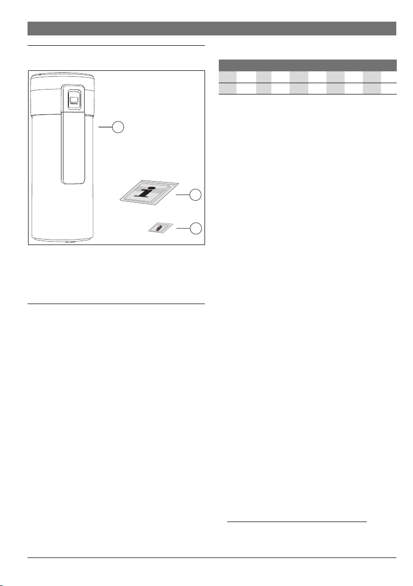
2 Standard delivery
Fig. 1
[1] Heat pump
[2] Set of printed documents for the appliance
[3] Condensate drain pipe
3 About the appliance
Appliances in the HP270... series are heat pumps which use
the energy in the ambient air for DHW heating.
3.1 Intended use
The appliance may only be used for DHW heating.
Using the boiler for any other purpose will be considered
incorrect use. Buderus accepts no liability for any damage
resulting from such use.
The appliance is not suitable for commercial or industrial
applications. It is approved for household use only.
3.2 Type overview
HP 270 -2 E 1FIIVs
HP 270 -2 E 0FIIVs
Table 2
[HP] Heat pump
[270] Cylinder capacity (in litres)
[-2] Version
[E] Electronic control
[1] Number of internal indirect coils in the cylinder
[F] Floor installation
[I] Indoor installation
[I] Air supply from inside
[V] Vertical installation
[S] Side connections
3.3 Data plate
The data plate is located on the rear side of the appliance.
There you will find details on the appliance performance, part
numbers, approval data, the coded date of manufacture (FD),
serial numbers and other specifications.
3.4 Description of appliance
Appliance for DHW heating with the following properties:
• Glass-lined steel cylinder with thermal insulation using CFCfree rigid polyurethane foam.
• Cylinder is corrosion-protected using internal magnesium
anode.
• The refrigerant and DHW circuits are completely separate.
• "Heat pump" operating mode stops automatically
inlet temperatures below -10 °C or over 35 °C.
• Upper limit pressure switch protects the refrigerant circuit.
• R134a used as the refrigerant.
• DHW temperatures between 30 °C and 70 °C (the default
setting for the DHW temperature is 50 °C).
1)
at air
1) chapter 8.5.2
6 720 809 134 (2013/09)Compress 3000 DW FII
Page 6
6 | About the appliance
6720804054-03.1V
670
25
94
331
630
735
1266
916
1835
350
700
735
445
160
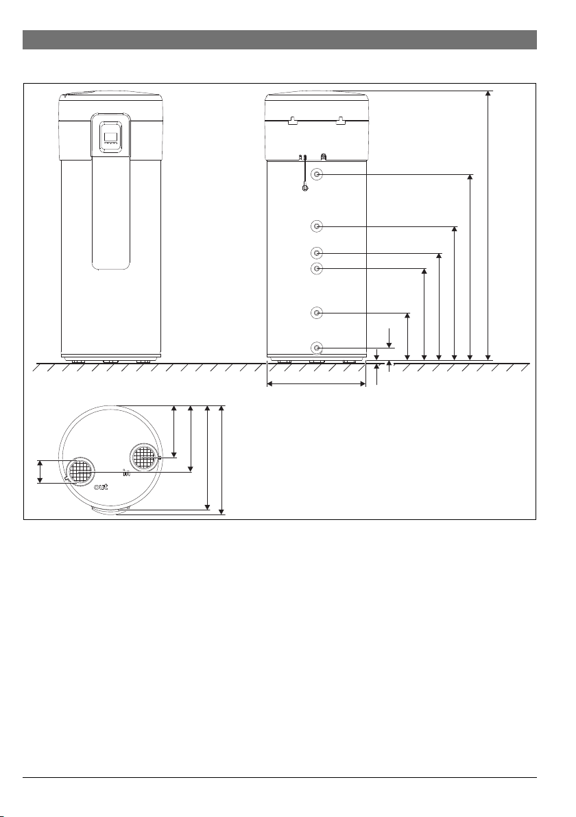
3.5 Dimensions and minimum clearances
Fig. 2 Appliance dimensions (in mm)
6 720 809 134 (2013/09) Compress 3000 DW FII
Page 7
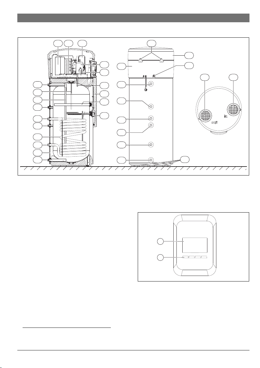
3.6 Appliance layout
1
2
4
3
6
11 12 13
18
24
25
16
17
3
1
5
23
21
15
22
14
19 20
6
10
9
5
4
7
2
8
6720804054-04.1V
26
6720804054-16.1V
1
2
Fig. 3 Heat pump
[1] Water inlet - G1"
[2] Internal indirect coil outlet - G1"
[3] Internal indirect coil inlet - G1"
[4] Sensor pocket for temperature sensor (data for solar
system or electric booster heater)
[5] DHW circulation line inlet - G3/4"
[6] Water outlet - G1"
[7] Internal indirect coil
[8] Thermal insulation
[9] Water inlet to condenser
[10] Water outlet from condenser
[11] Fan
[12] Evaporator
[13] Condenser (gas/water heat exchanger)
[14] Compressor
[15] Sensor pocket for DHW temperature sensor
[16] Magnesium anode
[17] Central heating resistor
[18] Adjustable feet (3x)
[19] Air outlet aperture
[20] Air inlet aperture
[21] Condensate outlet
[22] Circulation pump
1) model HP270-2E1... only
1)
1)
1)
About the appliance | 7
[23] Front protective covering
[24] Housing ring
[25] Housing lid
[26] Fastening for housing lid
Fig. 4 User interface
[1] Display
[2] Setting buttons
6 720 809 134 (2013/09)Compress 3000 DW FII
Page 8
8 | About the appliance
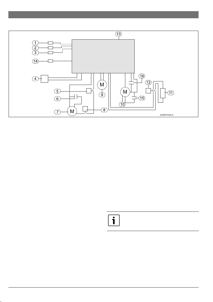
3.7 Wiring diagram
Fig. 5
[1] NTC temperature sensor for air inlet
[2] Flow NTC temperature sensor
[3] NTC temperature sensor in water inlet
[4] Power cable
[5] High Pressure Switch
[6] Electrical capacitor for compressor
[7] Compressor
[8] High limit safety cut-out for compressor
[9] Circulation pump
[10] Fan
[11] Resistor
[12] Resistor for high-limit safety cut-out
[13] Electronics box
[14] NTC temperature sensor (evaporator plates)
[15] Electrical capacitor for fan start
[16] Electrical capacitor for fan speed
3.8 Safety, control and protection devices
3.8.1 High Pressure Switch
If the operating pressure is outside of the recommended range,
the pressure switch switches off the appliance and displays a
fault ( chapter 11, page 28).
3.8.2 High limit safety cut-out
The high limit safety cut-out ensures that the water
temperature in the cylinder does not exceed the prescribed
limit. If the temperature limit is exceeded, the DHW heating
shuts down. The reset is performed manually by a certified
contractor.
3.8.3 Temperature sensor for air inlet
The temperature sensor measures the temperature of the inlet
air in the evaporator. If the measured value is outside the
operating temperature range, DHW heating automatically
switches from the "Combi" operating mode to "Electric booster
heater". If the appliance is in the "Heat pump" operating mode,
DHW heating is interrupted until the temperature returns to
within the permissible range.
3.9 Corrosion protection
The internal wall of the DHW cylinder is glass-lined (double
coating), making it neutral when in contact with water and
therefore suitable for potable water.
As an additional corrosion protection measure, the cylinder is
equipped with a magnesium anode. This must be inspected at
regular intervals and replaced if necessary.
The first inspection must take place 6
months after installation.
In regions with more corrosive water, safety measures (filter,
etc.) must be taken, and the magnesium anode must be
serviced more frequently.
6 720 809 134 (2013/09) Compress 3000 DW FII
Page 9
About the appliance | 9
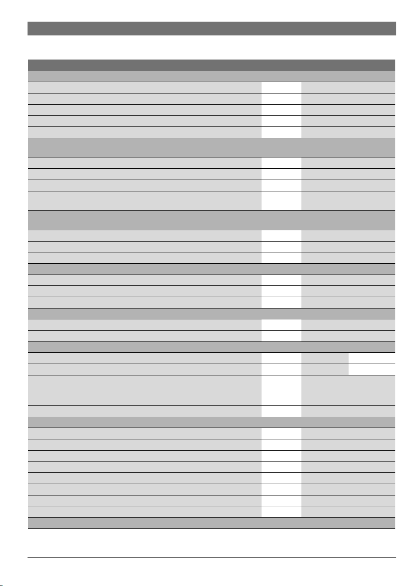
3.10 Technical properties
Unit HP270-2E0... HP270-2E1...
Heating output - in accordance with EN255-3, air temperature 20 °C, heating water from 15 °C to 45 °C
Output kW 1,7
Total heating output (including electric booster heater) kW 3,7
Performance coefficient (COP) – 4,3
Heat-up time h 5:00
Heat loss in 24h kWh/day 0,74
Heating output - in accordance with EN16147, XL cycle, air temperature 15 °C, heating water from 10 °C to 54 °C,
Tref > 52.5 °C
Performance coefficient (COP) – 3,20
Heat-up time h 8:48
Heat loss in 24h kWh/day 1,08
DHW volume, corresponds to water at a temperature of 40 °C, available after
heating
Heating output - in accordance with EN16147, XL cycle, air temperature 7 °C, heating water from 10 °C to 54 °C,
Tref > 52.5 °C
Performance coefficient (COP) – 2,79
Heat-up time h 10:38
Heat loss 24h kWh/day 0,97
Air inlet
Air flow rate (without/with pipework) - fan speed "SP1" m3/h 380/300
Air flow rate (without/with pipework) - fan speed "SP2" m3/h 490/300
Operating temperature °C -10 ... +35
Refrigerant circuit
Refrigerant R134a g 400
Maximum pressure bar 27
DHW
Cylinder capacity l 270 260
Area of heat exchanger (internal indirect coil) m
Maximum outlet temperature without/with electric booster heater °C 60/70
DHW volume per day, corresponds to a water temperature of 40 °C, air
temperature 20 °C, heating water from 15 °C to 60 °C
Maximum operating pressure bar/MPa 10/1
Electrical details
Mains power supply V ~230 (+10%/-10%)
Frequency Hz 50
Current rating (without/with electric booster heater) O 2.6/11.3
Max. rated consumption kW 0.6
Total heating output of the electric booster heater kW 2.0
Total max. rated consumption (including electric booster heater) kW 2.6
IP rating I
IP rating (without/with pipework) IP 21/24
General data
Table 3
l
2
l
372
-1.3
1200
6 720 809 134 (2013/09)Compress 3000 DW FII
Page 10
10 | Transport and storage
Unit HP270-2E0... HP270-2E1...
Sound pressure level with pipework (at a distance of 2 m) dB(A) 40
Dimensions, W x H x D mm 700 × 1835 × 735
Net weight (without packaging) kg 108 125
Table 3
Manual transport
4 Transport and storage
NOTICE: Damage caused by straps!
WARNING: Transport damage!
▶ Take care when handling the appliance.
▶ To avoid dropping and damaging the
appliance, do not pivot it.
NOTICE: Transport damage!
▶ To avoid transport damage, do not
remove the protective packaging. Wait
until the appliance is at the installation
location to remove the protective
packaging.
▶ Transport and set down the appliance
carefully. Jerky movements can damage
the internal glass-lined coating, the
components and their connections or the
external casing.
▶ Use suitable means of transport to bring
the appliance to the installation location
(special car, pallet truck, etc).
Straps can be placed around the cylinder in order to position
the appliance in its final location.
5 Installation
▶ The appliance may only be installed by an authorised
contractor.
▶ The heat pump installation must follow the applicable
regulations.
▶ Check that all pipe connections are intact and have not
shaken loose during transportation.
▶ Remove the front protective covering
( Fig. 3, [23]).
▶ Make sure that the straps do not scratch
or make indentations on the surface of the
appliance.
▶ Do not attach straps to the appliance
connections.
General information
The appliance is delivered on a single pallet and is protected
against transport damage by special packaging.
The appliance must be stored and transported vertically in its
original packaging
temperatures of -20 °C to +60 °C are permissible for storage
and transport.
1) Horizontal transportation is permitted over short distances,
provided that the conditions described above are fulfilled.
6 720 809 134 (2013/09) Compress 3000 DW FII
1)
and the cylinder must be empty. Ambient
5.1 Installation location
Please note the following when choosing the installation
location:
• The appliance must be installed in a dry, frost-free room.
The supply air temperature must be betw een -10 °C and
35 °C in order to optimise the appliance performance.
• The appliance must be installed on a sufficiently strong and
level surface.
• The air outlet and air inlet must not be in locations where
there is a risk of explosion cause by gas, steam or dust.
• Ensure that condensate drains correctly.
• The surf ace below the appliance must be strong enough (the
appliance weighs about 400 kg when the cylinder is filled,
NOTICE: Refrigerant leak!
▶ Only authorised contractors are
permitted to maintain and repair the
refrigerant circuit.
Page 11

Installation | 11
500
400
2200
430
6720804054-17.1V
with the weight distributed equally over its 3 adjustable
feet).
If the appliance only has one duct (inlet or
outlet duct), its operation may create
negative or positive pressure in the
installation room. If other burners are
already installed in the same place, please
bear in mind that the appliance requires a
clearance of at least 220 cm
and outlet in order to operate correctly.
Note: The clearance of 220 cm
2
for the air inlet
2
is required
for the correct functioning of the heat pump
only. In addition, you must ensure that the
burner has the necessary clearance.
To ensure faultless operation and easy access to all
components and connections for service and maintenance,
maintain the minimum clearances specified in Fig. 6.
▶ Assure correct positioning of all temperature sensors.
Fig. 7 Temperature sensor at the top of the cylinder
Fig. 6 Recommended minimum clearances (mm)
5.2 Installing the appliance
▶ Remove the foil and external protective packaging.
▶ Lift the appliance from its pallet and position it on its final
plinth.
▶ To correctly align the appliance at the installation location,
adjust the height of the adjustable feet.
Fig. 8 Temperature sensors (evaporator plates + air inlet)
To ensure that the system operates
faultlessly and the condensate drains
correctly, the appliance must be aligned
vertically. The appliance must not tilt more
than 1°, preferably in the direction of the
condensate drain.
6 720 809 134 (2013/09)Compress 3000 DW FII
Page 12

12 | Installation
L
2T
L
T1
L1
C1 C2
L2
L4
L3
L = L1+C1+L2
T1
L = L3+C2+L4
L=L +L
SP1: L 30m
T2
T1 T2
≤
2
1
NOTICE: Possible damage to external
casing!
▶ Do not tilt the appliance on his feet more
than 20°.
5.3 Connecting the ducts
The air inlet can be located in the installation room, in a
different room or outside. In the latter two cases, air inlet ducts
must be installed.
To ensure maximum appliance performance
and to prevent condensation forming on the
external duct walls, use thermally and
acoustically insulated ducts.
When choosing a room for the air inlet, observe the average air
temperature and required air flow rate ( Tab. 3). In order to
minimise air resistance, lay the air inlet and outlet ducts
(Ø 160 mm) as straight as possible.
The length (L
exceed the following values:
• 30 m at fan speed SP1
0.5 m duct 0.5 m
1m duct 1.0m
2 m duct 2.0 m
10 m hose 19.0 m
45° elbow 0.9 m
90° elbow 2.0 m
90° flexible curve 2.3 m
Weather grille 8 m 4m
Roof output 7 m 4m
Table 4
To ensure that condensate forming in the air inlet and air outlet
ducts drains from the appliance:
▶ Install air ducts horizontally or at a slight angle to the air inlet
and air outlet apertures on the top side of the appliance.
Installation with ducts
▶Activate “Duct” function ( page 24, chapter 8.6.4).
) of the air inlet and outlet ducts must not
eq
Air inlet
(IN)
Air outlet
(OUT)
L
eq
5.3.1 Open flue operation
If the heat pump is operated with air from the installation
location, the volume of the room must be at least 20 m
3
.
5.3.2 Outdoor air operation
If the pump is operated with outdoor air, the ducts must be
protected against the weather using the correct end pieces.
Fig. 9 Equivalent duct length (L)
[1] Air inlet
[2] Air outlet
L Fan speed
1)
Up to 30 m SP1
Table 5
1) chapter 8.6.4
5.4 Connecting the water pipes
Never close the water shut-off valve during
operation (Fig. 6, [4]).
6 720 809 134 (2013/09) Compress 3000 DW FII
Page 13

To prevent faults occurring due to sudden
pressure fluctuations in the supply:
▶ Fit a non-return valve and a pressure
control valve to the appliance supply.
NOTICE: Pipes can be damaged if treated
incorrectly.
▶ Do not allow pipes to become
contaminated during installation.
▶ If necessary, flush the pipes with water
prior to commissioning.
Prior to installation, thoroughly flush water
pipes as the water flow could be reduced by
contaminants and, in case of severe
contamination, be stopped completely.
▶ Fit a water filter to the water inlet.
NOTICE: Corrosion damage to the cylinder's
connections!
If the connections are made from copper:
▶ Use an isolation fitting for the hydraulic
connection
1)
. This extends the service
life of the magnesium anode.
1) Accessory not included in standard delivery
▶ Determine the nominal diameter of the room's water
installation. Please note the current water pressure and the
expected pressure loss.
▶ Carry out the water connection in accordance with the
applicable regulations. P lease observe the local regulations
on DHW installations.
▶ The water pipes can be rigid or flexible. To avoid corrosion,
take into account the behaviour of the materials used in the
pipe system and the connections.
To prevent heat loss and to ensure maximum appliance
performance:
▶ Thermally isolate the water connections.
Installation | 13
Safety valve
1)
▶ Fit the safety valve to the water inlet of the appliance.
If the water inlet pressure is higher than
8 bar - 80% of the allowable maximum value
(10 bar) -, install a reducing valve. The safety
valve is activated when the water pressure
exceeds the upper limit (
allowing water to drain off. A tundish
Tab.6, page15),
should
be provided for this purpose.
NEVER CLOSE OFF THE SAFETY VALVE
DRAIN.
Never install accessories between the safety
valve and the appliance water connection.
NOTICE:
The drain line from the safety valve must be
laid in a frost-free location. It must remain
open to the atmosphere and always be kept
in a sloped position.
5.5 Internal indirect coil connection
2)
The appliance is equipped with an additional internal indirect
coil which enables the solar system or boiler to provide
support.
When the water temperature in the cylinder re aches 80 °C, the
control switches off the support system. This prevents damage
to the refrigerant circuit in the heat pump and stops the high
limit safety cut-out from being activated.
WARNING: Risk of scalding!
Hot water can lead to severe scalding.
▶ Inform users of the danger of scalding and
always monitor the thermal disinfection
process. Install a thermostatic DHW
mixer.
If the internal indirect coil is not used:
▶ Seal off the internal indirect coil's inlet and outlet apertures
with plugs.
1) Accessory not included in standard delivery
2) HP270-2E1...model only
6 720 809 134 (2013/09)Compress 3000 DW FII
Page 14

14 | Installation
1.
2.
6720804054-11.1V
2
1
Water temperature sensor in cylinder
▶ Install DHW temperature sensor in the correct pipe
( Fig. 3, [4]).
▶ Insulate the pipe to prevent heat loss.
5.6 Connecting the DHW circulation line
Using circulation systems always reduces
efficiency.
With regard to the output, DHW circulation should only be used
when it is really needed. To reduce heat loss, circulation
systems which are connected to the DHW distribution system
must be controlled via a valve, time control or similar device.
5.7 Condensate hose connection
The condensate drain pipe is supplied
separately.
NOTICE: Damage to the appliance!
▶ Connect the condensate hose to the
condensate drain before installing the
part.
▶ Do not bend the condensate hose.
The condensate is drained on the rear side of the appliance.
▶ Connect the condensate hose to the
(Fig. 10, [1]).
▶ Connect the condensate hose to the collection area.
▶ Drain off condensate via a siphon drain (Fig. 10, [2]).
1)
condensate drain
Fig. 10 Condensate collection
[1] Condensate drain pipe
[2] Outlet siphon
5.8 DHW expansion vessel
1)
To prevent water loss from the safety valve, a
DHW expansion vessel can be installed.
▶ Install an expansion vessel at the water connection between
the cylinder and the safety assembly.
Tab. 6 serves as a reference for the selection of an expansion
vessel at a reference temperature of 60 °C. The capacity of the
expansion vessel must be selected subject to the water
pressure in the system.
1) Accessory not included in standard delivery
6 720 809 134 (2013/09) Compress 3000 DW FII
Page 15

Installation | 15
6720804054-12.1V
2
1
Capacity of the
expansion vessel
corresponding to the
switch-on pressure of
the safety valve
Cylinder
type
Safety
valve
(maximum
pressure)
Water
pressure
in the
system
212l
6bar
318l
425l
HP
270...
8bar
212l
312l
418l
212l
10 bar
312l
418l
Table 6
5.9 Filling the cylinder
NOTICE: Damage to the appliance!
▶ Prior to commissioning the appliance, fill
the cylinder with water and bleed the
system if necessary.
Automatic filling - systems with water pressure above 3 bar
▶ Open the water outlet valve and at least one hot water tap.
▶ Open the water inlet valve on the cylinder (Fig. 5, [4]).
The cylinder is filled.
▶ Do not close the hot water taps until the water f lows steadily
and is free from air bubbles.
The process of filling the cylinder is complete.
▶ Connect the appliance to the power supply via a separate
socket with an earth connection.
If the fault code "E09" appears on the display after a few
minutes, proceed as follows:
▶Fill manually.
Manual filling - systems with water pressure below 3 bar
▶ Open the water outlet valve and at least one hot water tap.
▶ Open the water inlet valve on the cylinder (Fig. 5, [4]).
The cylinder is filled.
▶ Do not close the hot water taps until the water f lows steadily
and is free from air bubbles.
▶ Connect the appliance to the power supply via a separate
socket with an earth connection.
▶ Set the selector switch on the heating pump (Fig. 11, [1]) to
"III".
Fig. 11 Heating pump
[1] Selector switch
[2] Air vent screw
▶ Select "Purg" operating mode ( page 24, chapter 8.6.5).
CAUTION: Risk of scalding!
▶ Ensure that draining water from the air
vent screw presents no risk to people or
property.
▶ Open the drain screw on the heating pump (Fig. 11, [2])
until the water flows steadily and without air bubbles.
▶ Close the drain screw on the heating pump.
▶ Wait around 5 minutes until the "Purg" operating mode has
finished.
▶ Set the selector switch on the heating pump to "I ".
The process of draining and filling the cylinder is complete.
If the fault code "E09" appears on the display after a few
minutes, proceed as follows:
▶ Clear the fault ( page 25, section "Resetting the fault
display").
▶ Refill manually.
5.9.1 Water quality
Inadequate water quality or contaminated water can damage
the appliance.
6 720 809 134 (2013/09)Compress 3000 DW FII
Page 16

16 | Electrical connection
Fig. 12 Water quality
Water treatment not required
(-0.5 < LSI < 1.5)
Water treatment required against scaling
(LSI > 1.5)
Water treatment required against corrosion
(LSI < -1.5)
Water treatment may be needed against corrosion
(-0.5 < LSI < -1.5)
LSI Langelier Saturation Index
Table 7
Please note that the Langelier saturation Index depends on the
water temperature and the above information considers two
extremes: 10 °C et 70 °C.
While corrosion is higher at low water temperature, scaling is
more important at higher water temperature.
In case of water hardness above 600 mg/l, the Langelier
saturation index must be determined to evaluate the necessity
for water treatment.
Notify certified contractor.
Water conductivity for sacrificial anodes
130 S/cm - 1500 S/cm
Table 8 Water conductivity
Do not use fully desalinated, distilled or
deionised water for this appliance type.
DANGER: Risk of electric shock!
▶ Isolate the appliance from the power
supply using the fuse or another electrical
protection device before carrying out any
work on electrical parts.
DANGER: Electric shock!
The electrical capacitor must discharge after
the appliance has been switched off.
▶ Wait at least 5 minutes.
DANGER:
To ensure compliance with all safety
requirements, defective power cables may
only be replaced by an authorised contractor.
All control, monitoring and safety equipment for this appliance
has been subjected to intense scrutiny and is ready for
operation.
The appliance is set at the factory to a power
supply of 230 V (single phase).
CAUTION:
Current protection!
▶T
The appliance is equipped with a cable for the mains
connection (1.5 m long) and is ready to be connected to a
socket (230 V AC/50 Hz).
For safety and maintenance purposes,
ensure that the socket is accessible after
installation.
Electric shock!
he control unit must have a separate
connection for the appliance with a 30 mA
safety switch and earth connection.
6 Electrical connection
The appliance may only be installed by an
authorised contractor.
6 720 809 134 (2013/09) Compress 3000 DW FII
6.1 Appliance's electrical connection
The electrical connection must meet the
current standards for electrical installations
in the country of use.
Page 17

Commissioning | 17
6720804054-16.1V
1
2
▶ The power connections must be as short as possible in order
to protect the system against overloading; for example,
during a storm.
▶ Connect the appliance to the power supply via a separate
socket with an earth connection.
7Commissioning
7.1 Before commissioning
NOTICE: Damage to the appliance!
After installing the appliance in its final
position, wait at least 30 minutes before
switching it on.
NOTICE: Do not start the appliance without
water!
▶ Only operate the appliance once it has
been filled with potable water.
▶ Check whether the cylinder is filled with water.
▶ Check all connections for tightness.
▶ Check the electrical connection.
7.2 Switching the appliance on/off
Switching ON
▶ The appliance must be connected to the power supply via a
separate socket with an earth connection.
For the first few seconds after switching on, the display will
not be activated.
Normal start
Time Activity
0 - 1 minutes Water temperature check (circulation pump in
operation)
1 - 2 minutes Wait mode
2 - 4 minutes Air temperature check (fan in operation)
> 4 minutes Compressor in operation
Table 9
Switching off
▶ Switch off the appliance at the power connection.
NOTICE: Damage to the appliance!
Minus temperatures can cause the water to
freeze.
▶ Do not interrupt the power supply. This
will ensure that the "frost protection"
function keeps working.
▶ Set the appliance to the "Off" operating
mode ( cha pter 8.4.4, page 19).
-or-
▶ Drain the appliance fully.
8Operation
Once the compressor has been started, the
appliance must run for at least 5 minutes
before it can be switched off again.
Fig. 13 User interface
[1] Display
[2] Selector keys
6 720 809 134 (2013/09)Compress 3000 DW FII
Page 18

18 | Operation
2 3
4
5
6
8
9
12
11
16
14
13
6720645393-10.1V
1 7
15
10
6720646160-13.1V
6720646160-14.1V
menu
-
ok
+
<3s
Fig. 14 Display
[1] Electrical heating mode
[2] DHW heating by heat pump
[3] External heating (solar or boiler)
[4] Information
[5] Input of adjustable parameters
[6] Error display
[7] Service menu selection
[8] Days of the week
[9] "Auto/Man" operation
[10] ON/OFF indicator
[11] "Prog" menu selection
[12] Setting the hour
[13] Runtime
[14] Power consumption
[15] Code for cylinder temperature sensors
[16] Frost protection
▶ Press the "+" or "-" button to set the desired value.
Fig. 15 Setting the temperature
▶ Press the "OK" button to confirm the setting.
The set value flashes until the setting is
confirmed.
If the setting is not confirmed within
10 seconds, the previously set value is
retained.
Once the temperature has been set, the
display indicates the water temperature in
the cylinder.
8.3 Main menu
Calling up the main m enu
▶ Press and hold the "Menu" button for max. 3 seconds.
8.1 Operation modes
" " symbol is displayed
Operating times as set (P1, P2 or P3).
" " symbol is displayed
Continuous operation (24 h/7 days) without time setting or in
"Full" operating mode.
8.2 Setting the domestic hot water temperature
The water temperature is set to 50 °C at the
factory.
6 720 809 134 (2013/09) Compress 3000 DW FII
Fig. 16 Calling up the main menu
Once you have called up the main menu, you can select the
following menus/submenus:
• Prog - Operating modes
–Manual
–P1
–P2
–P3
–Full
–Off
• Mode - H eat types
– "Electrical" operating mode
– "Heat pump" mode
– "Combi" operating mode
• Set - Settings
Page 19

Operation | 19
6720646160-37.1V
6720646160-08.1V
–Date
– Prog - Programming of the operating times
– Leg - Legionella program
–Duct - use of ducts
–Purg - Drain
– Fset - Default settings
• Info - Information
▶ Use the "+" or "-" button to select the required menu.
▶Confirm by pressing "ok".
To switch to the previous menu:
▶ Press the "Menu" button.
-or-
▶ Do not press any buttons for 15 seconds.
8.4 "Prog" submenu - Operating modes
You can set 7 different operating times in the "Prog" submenu.
•Manual
•P1
•P2
•P3
•Full
•Off
8.4.1 "Manual" operating mode
Selecting this operating mod e puts the appliance into
continuous operation in order to keep the temperature at the
set value for a longer period of time. The heat appliance can be
set in the main menu using the "Mode" function
( chapter 8.5).
"P2" and "P3" operating modes
Selecting this menu causes the appliance to run according to
the user-set operating times ( "P2" and "P3" operating times,
page 22).
8.4.3 "Full" operating mode
In this operating mode, two heat appliances are used at the
same time: the heat pump and the electric booster heater.
The appliance performance decreases in
"Full" operating mode. For this reason, it
must only be used when the water
temperature needs to be increased rapidly.
Fig. 18 "Full" operating mode
The water temperature can be set to between 30 °C and 70 °C.
Both heat appliances are used at the same
time until the desired temperature is
reached.
Only the electric booster heater is used at
temperatures above 60 °C.
The display shows "Full" until the desired
temperature is reached.
Fig. 17 "Manual" operating mode
8.4.2 "P1", "P2" and "P3" operating modes
"P1" operating mode
Selecting this menu causes the appliance to run according to
the factory-set operating times ( "P1" operating time,
page 22).
As soon as the set DHW temperature is reached, the appliance
switches from the "Full" operatin g mode back to the previously
set operating mode.
"Quick" activation of the "Full" operating mode
▶ Press and hold the "+" and "-" buttons for more than
3seconds.
8.4.4 "OFF" operating mode
In this operating mode, the appliance is switched off. If
necessary, the electric booster heater is switched on by itself
for the frost protection function.
6 720 809 134 (2013/09)Compress 3000 DW FII
Page 20

20 | Operation
6720646160-10.1V
6720646160-19.1V
6720646160-07.1V
6720646160-06.1V
6720646160-09.1V
Fig. 19 "OFF" operating mode
Frost protection
The electric booster heater starts up when the water
temperature in the cylinder falls to 5 °C and switches off again
when the temperature reaches 8 °C.
8.5 "Mode" submenu - Heating mode
3 different types of heating mode can be selected in the "Mode"
submenu.
• Electrical heating mode
• "Heat pump" operating mode
• "Combi" operating mode
8.5.2 "Heat pump" operating mode
Water heating is only guaranteed when the
inlet air temperature is between -10 °C and
35 °C.
Selecting this operating mode means that the heat pump is the
only heat appliance used.
Fig. 22 "Heat pump" operating mode
The water temperature can be set to between 30 °C and 60 °C.
At very low temperatures, the frost
protection function ( page 20) is
activated.
8.5.3 "Combi" operating mode
In this operating mode, two heat appliances are used
depending on the situation: the heat pump or the electric
booster heater.
Fig. 20 "Mode" function
8.5.1 Electrical heating mode
In this operating mode, the electric booster heater is the only
heat appliance used.
Fig. 23 "Combi" operating mode
The water temperature can be set to between 30 °C and 70 °C.
If the water temperature in the cylinder is
below 60 °C and the inlet air temperature is
between -10 °C and 35 °C, the heat pump is
the only heat appliance used. Otherwise, the
Fig. 21 Electrical heating mode
electric booster heater is switched on.
The water temperature can be set to between 30 °C and 70 °C.
6 720 809 134 (2013/09) Compress 3000 DW FII
Page 21

Operation | 21
6720646160-18.1V
6720646160-11.1V
6720646160-12.1V
6720646160-15.1V
8.6 "Set" submenu - Settings
You can set various parameters in the "Set" submenu:
•Date
• Prog - Operating times
•Leg - Legionella
•Duct - use of ducts
•Purg - Drain
• Fset - Default settings
Fig. 24 "Set" function
8.6.1 Date - Setting the temperature unit, date, time and day of the week
▶ Set the day of the week using the "+" or "-" button.
Fig. 26 Setting the weekday
▶ Confirm by pressing "OK".
The hour flashes on the display.
▶ Set the hour using the "+" or "-" button.
▶ Confirm by pressing "OK".
The minutes flash on the display.
▶ Set the minutes using the "+" or "-" button.
▶ Confirm by pressing "OK".
The process of setting the clock is complete.
8.6.2 Prog - Programming of the operating times
In the "Prog" submenu, you can set the operation period for the
heat pump.
Fig. 25 Setting the date
▶ Select the temperature unit using the "+" or "-" button.
▶Confirm by pressing "OK".
The year flashes on the display.
▶ Set the year using the "+" or "-" button.
▶Confirm by pressing "OK".
The month flashes on the display.
▶ Set the month using the "+" or "-" button.
▶Confirm by pressing "OK".
The day flashes on the display.
▶ Set the day using the "+" or "-" button.
▶Confirm by pressing "OK".
The day flashes on the display.
Monday is set as the first day of the week by
default. Depending on individual
requirements, the user can choose to set a
different day as the first day of the week.
Fig. 27 "Prog" function
The following menus can be called up in the "Prog" submenu:
• "P1" operating time (days 1 to 5)
• "P1" operating time (days 6 and 7)
• "P2" operating time (days 1 to 5)
• "P2" operating time (days 6 and 7)
• "P3" operating time (days 1 to 5)
• "P3" operating time (days 6 and 7)
6 720 809 134 (2013/09)Compress 3000 DW FII
Page 22

22 | Operation
6720646160-16.1V
6720646160-35.1V
6720646160-39.2V
6720646160-40.2V
6720646160-41.1V
"P1" operating time
The heat pump only goes into operation during the operating
times set at the factory. These cannot be changed:
Days 1 - 5: [00:00 06:00] and [16:00 19:00]
Days 6 - 7: [02:00 08:00]
Fig. 28 "P1" operating time
"P2" and "P3" operating times
The heat pump runs according to the operating times set by the
user.
Fig. 29 "P2" and "P3" operating times
Setting the operating times for "P2" and "P3"
4 operating times are set for each function:
•2 operating times for days 1 to 5
• 2 operating times for days 6 and 7
Setting the operating times
▶ Call up function "P2" or "P3" ( chapter 8.4).
▶Press "OK".
The start of the first operating time flashes.
▶ Set the start of the operating time using the "+" and "-"
buttons.
▶Press "OK".
The end of the first operating time flashes.
▶ Set the run time using the "+" and "-" buttons.
▶Press "OK".
The start of the second operating time flashes.
Fig. 31 Start of the second operating time
If the start of the second operating time is set
so that it is within the fi rst operating time, the
first operating time ends automatically when
the second operating time starts.
▶ Set the start of the second operating time using the "+" and
"-" buttons.
▶Press "OK".
The end of the second operating time flashes.
▶ Set the run time using the "+" and "-" buttons.
▶Press "OK".
The operating time for days 1 to 5 is saved.
Fig. 32 Start of the first operating time for days 6 and 7
▶ Repeat the steps above for the operating times for days 6
and 7.
Once you have set the second operating time f or days 6 and 7,
the process of setting the operating times is complete.
Fig. 30 Start of the first operating time
6 720 809 134 (2013/09) Compress 3000 DW FII
Page 23

Fig. 35 "Leg" function
6720646160-38.1V
1 2 3 4
6720804054-14.1V
6720646160-17.1V
Operation | 23
Fig. 33 Setting operating times
[1] Start of the first operating time
[2] End of the first operating time
[3] Start of the second operating time
[4] End of the second operating time
Deleting the operating time
▶ Set the start and end of the operating time to the same time.
The operating time is deleted.
If you do not wish to set a second operating time:
▶ Set the start and end of the second operating time to the
same time.
The display will show "--:--".
Fig. 34
" " symbol is displayed
During appliance operating time.
" " symbol is di splayed
Outside of appliance operating time.
8.6.3 "Leg" - Automatic thermal disinfection
The "Leg" function allows you to activate/deactivate thermal
disinfection. This process is used to kill bacteria and must be
performed by the user at least once a week.
This function is deactivated on the appliance
at the factory.
When the disinfection is activated, all other
settings are temporarily suspended.
WARNING: Risk of scalding!
Hot water can lead to severe scalding.
▶ Only schedule thermal disinfection for
periods outside normal usage times.
▶ Inform occupants of the building of the
danger of scalding and always monitor
the thermal disinfection process. Install a
thermostatic DHW mixer.
The disinfection takes max. 48 h. During the
first 24 hours, the appliance is in the "Combi"
operating mode. If it does not reach 70 °C,
the appliance switches to the "Full" operating
mode for the next 24 hours.
Activating the automatic "Leg" function
The DHW temperature is automatically set to
70 °C.
▶ Call up the "Leg" function and press "OK".
" " flashes on the display.
▶Press "+".
" " flashes on the display.
▶Press "OK".
The "Leg" function is activated and the first day of the week
flashes.
Set the day of the week for disinfection.
▶ Select the day using the "+" and "-" buttons.
▶Press "OK".
6 720 809 134 (2013/09)Compress 3000 DW FII
Page 24

24 | Operation
6720807839-01.1V
6720801967-02.1V
6720804054-10.1V
Set the time for disinfection.
▶ Select the time using the "+" and "-" buttons.
▶Press "OK".
As soon as the temperature reaches 70 °C, the appliance
switches back to the previously set operating mode.
Activating the manual "Leg" function
▶ Call up the "Leg" function and press "OK".
" " flashes on the display.
▶Press "OK".
The "Leg" function is active.
The DHW temperature is automatically set to
70 °C.
As soon as the temperature reaches 70 °C, the appliance
switches back to the previously set operating mode.
To repeat the disinfection process, you must
reactivate it.
Cancelling the "Leg" function.
▶ Call up the "Leg" function and press "OK".
" " flashes on the display.
▶ Press "+" until the display shows "LstP".
▶Press "OK".
The current Legionella program is cancelled.
▶ Press « + » or « - » to define the use of ducts:
– « dOFF » : installation without ducts
– « dON » : installation with ducts
▶Press «OK».
8.6.5 "Purg" - Drain
The "Purg" function can be used to drain water from the system.
Fig. 37 "Purg" function
Switching on the "Purg" function.
▶ Call up the "Purg" function and press "OK".
The pump is switched on.
The display indicates the time remaining until the draining
procedure is complete (in minutes).
After 5 minutes, the appliance reverts to the previously
selected operating mode.
8.6.6 "Fset" - Default settings
The "Fset" function can be used to restore the default settings.
This only ends the current program; the
weekly repetition is still active.
8.6.4 « Duct » - use of ducts
Fig. 38 "Fset" function
Switching on the "Fset" function
▶ Call up the "Fset" function and press "OK".
The display shows "Fset".
▶Press "OK".
After 10 seconds, the default settings are restored
( chapter 8.9).
Fig. 36 « Duct » function
Switching on the « Duct » function
▶ Select « Duct » function and press « OK ».
The display shows “dOFF”.
6 720 809 134 (2013/09) Compress 3000 DW FII
8.7 "Info" submenu - Information
With the "Info" function, it is possible to display the total
consumption for the last 30 days.
Page 25

Fig. 39 "Info" function
6720646160-36.1V
6720646160-42.1V
6720800765-04.1V
menu
-
ok
+
6720646160-21.1V
menu
-
ok
+
>3s
6720646160-37.1V
Displaying the consumption
▶ Call up the "Info" function and press "OK".
The display shows the total consumption (in kWh).
Resetting the consumption
The display shows the total consumption.
▶ Press "-".
"Del" flashes on the display.
Environmental protection/Recycling | 25
Resetting the fault display
▶ Press and hold the "OK" button for at least 3 seconds.
Fig. 42 Resetting the system
8.9 Default settings
After setting the temperature units and the time, the appliance
adopts the default settings.
• Heating mode: "Combi" ( chapter 8.5)
• Operating mode: "Manual" (chapter 8.4.1)
• Selected temperature: 50 °C
Fig. 40 "Del" function
▶Press "OK".
The counter is reset.
8.8 Fault diagnosis
The appliance is equipped with a system for fault diagnosis.
Malfunctions are displayed on the digital display by means of a
fault code ( Tab. 10, page 28) and a fault symbol ( Fig. 14,
[6]). The fault must be eliminate and the appliance
recommissioned before it is ready for use again. Chapter 11
gives an overview of the faults.
Fig. 41 Fault display with associate fault code
Fig. 43 Initial menu
9 Environmental protection/Recycling
Environmental protection is one of the fundamental company
policies of the Bosch Group.
Product quality, efficiency and environmental protection are
equally important objectives for us. We comply with all
environmental protection laws and regulations.
In order to protect the environment, we use the latest
technologies and the best materials whilst bearing in mind the
economic implications.
Packaging
Where packaging is concerned, we participate in the relevant
local recycling systems in order to ensure optimum recycling.
All of our packaging materials are environmentally friendly and
can be reused.
6 720 809 134 (2013/09)Compress 3000 DW FII
Page 26

26 | Service
6720800765-05.1V
Obsolete equipment
Used appliances contain materials that can be reused.
The assemblies are easy to separate and the types of plastic are
identified. In this manner the individual components are easily
sorted and added into the recycling and disposal systems.
10 Service
DANGER: Risk of electric shock!
▶ Isolate the appliance from the powe r
supply using the fuse or another
protection device before carrying out any
work on electrical parts.
NOTICE: Damage to the appliance!
▶ Do not shut off the water supply while the
appliance is in operation.
10.1 General inspections
Check the appliance regularly for faults.
▶ Keep the appliance and the installation location clean.
▶ Dust the system regularly using a damp cloth.
In this way, leaks can be identified and repaired at an early
stage.
▶ Check all connections regularly for tightness.
10.2 Checking/replacing the magnesium anode
The appliance is protected against corrosion
by a magnesium anode in the cylinder.
NOTICE: Damage to the appliance!
The magnesium anode must be installed
before commissioning the appliance.
NOTICE: Damage to the appliance!
Check the magnesium anode annually and
replace if required. Appliances operated
without this protection are excluded from
our warranty.
The internal wall of the DHW cylinder is coated with a double
glass lining. The coating is designed for normal quality water.
When using more corrosive water, the warranty only applies if
additional safety measures have been taken (e.g. the use of an
isolation fitting) and the magnesium anode is checked more
frequently.
To check the protective anode:
▶ Isolate the appliance from the power supply.
▶ Remove protective coverings.
WARNING: Risk of scalding!
▶ Before removing the magnesium anode,
drain about 75 litres of water from the
cylinder.
▶ Remove the magnesium anode.
Fig. 44 Checking the state of the magnesium anode
▶ Check the state of the magnesium anode and replace if
necessary.
10.3 Cleaning
▶ Check and clean the evaporator regularly.
▶ The air inlet and air outlet apertures must be unobstructed
and accessible.
▶ Check the air grille, air filter and air ducts regularly and clean
them if necessary.
10.4 Condensate pipe
▶ Disconnect the condensate hose from the condensate
drain.
▶ Check the drain and/or hose for contamination and clean if
necessary.
▶ Reconnect the condensate hose to the condensate drain.
10.5 Safety valve
▶ Open the safety valve at least once a month ( Fig. 45) to
ensure that it is functional.
6 720 809 134 (2013/09) Compress 3000 DW FII
Page 27

Service | 27
1
6720608467-18.2AL
2
6720646160-27.1V
2
1
▶ Push the reset button until it stops ( Fig. 46, [1]).
Fig. 45 Safety valve
[1] Safety valve
[2] Sequence
CAUTION: Risk of scalding!
▶ Ensure that draining water from the
safety valve presents no risk to people or
property.
10.6 Refrigerant circuit
NOTICE: Refrigerant leak!
▶ Maintenance work may only be carried
out on the refrigerant circuit (e.g. on the
compressor, condenser, evaporator,
expansion vessel, etc.) by a certified
contractor.
10.7 High limit safety cut-out
The appliance is equipped with an automatic safety facility.
This safety facility switches off the DHW cylinder in order to
prevent the risk of injury if the DHW cylinder water temperature
rises above a certain limit.
NOTICE: The high limit safety cut-out may
only be reset by a qualified contractor!
The high limit safety cut-out must be reset
manually, but only once the cause of the fault
has been eliminated.
Resetting the high limit safety cut-out
▶ Remove the front protective covering ( Fig. 3, [24]).
▶ Remove the protective cap from the resistor.
Fig. 46 Temperature control unit
[1] Reset button
[2] Temperature setting of the high limit safety cut-out.
After resetting, ensure that the temperature
controller is in the position shown in Fig. 46.
Do not damage the sealing.
10.8 Draining the cylinder
CAUTION: Risk of scalding!
Check the appliance's DHW temperature
before opening the safety valve.
▶ Wait until the water temperature has
dropped enough to prevent scalding and
other damage.
▶ Isolate the appliance from the power supply.
▶ Close the water shut-off valve at the cold water inlet and
open one DHW tap.
▶ Open the drain tap.
-or-
▶Open safety valve.
▶ Wait until the water stops flowing out of the safety valve
drain tap and the appliance has been completely drained.
10.9 "Service" menu
This menu is meant to assist the contractor
and may be used by the contractor only.
6 720 809 134 (2013/09)Compress 3000 DW FII
Page 28

28 | Display
11 Display
11.1 Faults that are displayed
Installation, service and maintenance may only be carried out by an certified contractor. The following table lists the fault codes and
their remedies.
Display Description Remedy
E01 Fault in the temperature sensor at the top of the cylinder Notify certified contractor
E02 Fault in the temperature sensor at the bottom of the cylinder Notify certified contractor
E03 Temperature sensor for air inlet not working Notify certified contractor
E04 Temperature in cylinder 80 °C If the problem persists after pressing "OK", notify a
E05 NTC temperature sensor (evaporator plates) not working Notify certified contractor
E06 Setting buttons hold down for longer than 30 seconds. Release buttons
E07 Accessory 7 736 501 8391) not (correctly) installed
E08 Accessory 7 736 501 8391) not (correctly) installed Notify certified contractor
E09 System emptied incorrectly
Water shortage (> 12h)
Fault in the pump
E10 Resistor not working
High limit safety cut-out not working
Temperature of high limit safety cut-out set to a lower value
than the appliance
E11 Fault in the fan
Pressure loss in the pipes
Leaks in refrigerant circuit
Fault in the compressor
Expansion valve not working
Drying filter not working
Table 10 Fault codes
1) Not available
certified contractor.
Notify certified contractor
Notify certified contractor
Clear the fault
Notify certified contractor
Notify certified contractor
Notify certified contractor
11.2 Display
Display Description Note
HOT Supply air temperature 35 °C System stops automatically in the "Heat pump" operating
COLD Supply air temperature -10 °C
Table 11 Display
6 720 809 134 (2013/09) Compress 3000 DW FII
mode if the air inlet temperature is below -10 °C or above
35 °C. General operating conditions are checked on an
hourly basis.
Page 29

Notes
| 29
6 720 809 134 (2013/09)Compress 3000 DW FII
Page 30

30 |
Notes
6 720 809 134 (2013/09) Compress 3000 DW FII
Page 31

Notes
| 31
6 720 809 134 (2013/09)Compress 3000 DW FII
Page 32

Bosch Thermotechnik GmbH
Junkersstrasse 20-24
D-73249 Wernau
www.bosch-thermotechnology.com
 Loading...