

Page 1
Air-Water Split Heat Pump
6 720 814 470-00.2I
VOGEL&NOOT
CLIMATE CONTROL SYSTEMS
Compress 3000 AW
230V 1N~ / 400V 3N~
Operating instructions
6 720 818 009(2015/07)
Page 2
2 | Table of Contents
VOGEL&NOOT
CLIMATE CONTROL SYSTEMS
Table of Contents
1 Key to symbols and safety instructions . . . . . . . . . . . . . . . . . . . 2
1.1 Key to symbols . . . . . . . . . . . . . . . . . . . . . . . . . . . . . . . . . 2
1.2 General safety instructions . . . . . . . . . . . . . . . . . . . . . . . . 3
2 General . . . . . . . . . . . . . . . . . . . . . . . . . . . . . . . . . . . . . . . . . . . . . . 3
2.1 Control unit . . . . . . . . . . . . . . . . . . . . . . . . . . . . . . . . . . . . 3
2.2 Use . . . . . . . . . . . . . . . . . . . . . . . . . . . . . . . . . . . . . . . . . . . 3
3 Overview of system . . . . . . . . . . . . . . . . . . . . . . . . . . . . . . . . . . . . 4
3.1 Description of the functions . . . . . . . . . . . . . . . . . . . . . . . 4
4 Overview of the most frequently used functions . . . . . . . . . . . 6
4.1 Changing the room temperature . . . . . . . . . . . . . . . . . . . 7
4.2 DHW settings . . . . . . . . . . . . . . . . . . . . . . . . . . . . . . . . . . . 7
4.3 Setting the operating mode . . . . . . . . . . . . . . . . . . . . . . . 8
4.4 Selecting a heating circuit for the standard display . . . . 8
4.5 Favourite functions . . . . . . . . . . . . . . . . . . . . . . . . . . . . . . 8
5 Maintenance . . . . . . . . . . . . . . . . . . . . . . . . . . . . . . . . . . . . . . . . . 9
5.1 Remove dirt and leaves . . . . . . . . . . . . . . . . . . . . . . . . . . . 9
5.2 Protective covers . . . . . . . . . . . . . . . . . . . . . . . . . . . . . . . 9
5.3 Evaporator . . . . . . . . . . . . . . . . . . . . . . . . . . . . . . . . . . . . . 9
5.4 Snow and ice . . . . . . . . . . . . . . . . . . . . . . . . . . . . . . . . . . . 9
5.5 Moisture . . . . . . . . . . . . . . . . . . . . . . . . . . . . . . . . . . . . . . . 9
5.6 Leakage tests . . . . . . . . . . . . . . . . . . . . . . . . . . . . . . . . . . . 9
5.7 Checking the safety valves . . . . . . . . . . . . . . . . . . . . . . . . 9
5.8 Particle filter . . . . . . . . . . . . . . . . . . . . . . . . . . . . . . . . . . . 9
5.9 Pressure switch and overheating protection . . . . . . . . 10
1 Key to symbols and safety instructions
1.1 Key to symbols
Warnings
Warnings in this document are identified by a warning
triangle printed against a grey background.
Keywords at the start of a warning indicate the type and
seriousness of the ensuing risk if measures to prevent
the risk are not taken.
The following keywords are defined and can be used in this document:
• NOTICE indicates a situation that could result in damage to property
or equipment.
• CAUTION indicates a situation that could result in minor to medium
injury.
• WARNING indicates a situation that could result in severe injury or
death.
• DANGER indicates a situation that will result in severe injury or
death.
Important information
This symbol indicates important information where
there is no risk to people or property.
Additional symbols
Symbol Explanation
▶ Step in an action sequence
Cross-reference to another part of the document
• List entry
– List entry (second level)
Table 1
6 Internet connection via integrated IP module . . . . . . . . . . . 12
7 Environment / disposal . . . . . . . . . . . . . . . . . . . . . . . . . . . . . . . 12
Technical terms . . . . . . . . . . . . . . . . . . . . . . . . . . . . . . . . . . . . . . . . . . 13
Compress 3000 AW6 720 818 009 (2015/07)
Page 3

General | 3
VOGEL&NOOT
CLIMATE CONTROL SYSTEMS
1.2 General safety instructions
These operating instructions are intended for the user of the heating
system.
▶ Read any operating instructions (heat pump, heating controls, etc.)
carefully before operation and keep them.
▶ Observe the safety instructions and warnings.
Intended use
This heat pump must only be used as a heat appliance in a sealed hot
water heating system for domestic purposes.
Any other use is considered inappropriate. Any damage that results from
such use is excluded from liability.
Safety of electrical appliances for domestic use and similar
purposes
The following requirements apply in accordance with EN 60335-1 in
order to prevent hazards from occurring when using electrical
appliances:
“This appliance can be used by children of 8 years and older, as well as
by people with reduced physical, sensory or mental capabilities or
lacking in experience and knowledge, if they are supervised and have
been given instruction in the safe use of the appliance and understand
the resulting dangers. Children must not play with the appliance.
Cleaning and user maintenance must not be performed by children
without supervision.”
“If the power cable is damaged, it must be replaced by the manufacturer,
its customer service department or a similarly qualified person, so that
risks are avoided.”
Inspection and maintenance
If there is a lack of cleaning, inspection or maintenance, or if these are
carried out incorrectly, this may result in material damage and/or
personal injury, including possible loss of life.
▶ Have work carried out only by an approved contractor.
▶ Have any defects rectified immediately.
▶ Have the heating system inspected once a year by an approved
contractor, and have any required maintenance or cleaning work
carried out.
▶ Have the heat source cleaned at least every two years.
▶ We recommend that you enter into a contract covering an annual
inspection and needs-based maintenance with an approved
contractor.
Modifications and repairs
Unprofessional modifications to the heat pump or other parts of the
heating system can result in injury and/or damage to property or
equipment.
▶ Have any work carried out only by an authorised contractor.
▶ Do not remove the casing of the heat pump.
▶ Do not modify the heat pump or other parts of the heating system in
any way.
2General
Compress 3000 heat pumps belong to a series of heating systems that
recover energy from the outdoor air for heating and DHW heating.
By reversing this process and removing heat from the heating water and
releasing it to the outdoor air, the heat pump can also be used for cooling
if necessary. To do this however, the heating system must be configured
for cooling mode.
In order to obtain a complete heating system, the heat pump which is set
up outdoors must be connected to an indoor unit in the building and in
some cases also to an existing external heat source, a boiler for example.
The indoor unit with integrated electric booster heater or external heat
source serve as auxiliary heating when the heat energy demand is
particularly high, e.g. if the outside temperature is too low for the heat
pump to operate effectively.
The heating system is controlled by a user interface which is located in
the indoor unit. The user interface controls the system using a range of
different settings for the heating, cooling, DHW and other operations.
The monitoring function switches the heat pump off in the event that
faults occur for example, as this prevents the main components being
damaged.
2.1 Control unit
The user interface in the indoor unit controls the heat production based
on the outdoor sensor values, possibly in combination with the room
controller (accessory). The temperature in the building is adapted
automatically, based on the outside temperature.
The user specifies the temperature of the heating system by setting the
required room temperature at the user interface or room controller.
Various accessories (e.g. swimming pool, solar and room controller) can
be connected to the indoor unit. Additional functions and setting options
therefore become available and can also be controlled via the user
interface. For more information on accessories, refer to the relevant
instructions.
2.2 Use
Following the installation and commissioning of the heat pump and
indoor unit, specific tasks must be performed at regular intervals. These
include checking whether alarms have been triggered and simple
maintenance tasks. These actions can normally be performed by the
user unassisted. However, if problems persist it may be necessary to
contact the system installer.
Room air
The air in the installation room must be free of combustible or chemically
aggressive substances.
▶ Do not use or store combustible or explosive materials (paper,
propellants, thinners, paints, etc.) within the vicinity of the
appliance.
▶ Do not use or store corrosive substances (solvents, adhesives,
chlorinated cleaning agents, etc.) within the vicinity of the appliance.
6 720 818 009 (2015/07)Compress 3000 AW
Page 4
4 | Overview of system
6 720 814 470-03.1l
VOGEL&NOOT
CLIMATE CONTROL SYSTEMS
3 Overview of system
The heating system consists of two parts: the heat pump outdoors and
the indoor unit with or without integrated electric booster heater in the
building (AWES/AWMS/AWMSS).
An external heat source can also be connected, in which case an existing
electric, gas-fired or oil-fired boiler (AWBS) can be used as the auxiliary
heater.
The heating systems are normally designed with one of these
alternatives in mind. However, as the system is highly flexible, countless
other configurations are possible.
3.1 Description of the functions
In a house with water based heating a difference is made between
heating water and domestic hot water (DHW). The heating water is for
radiators and floor coils and hot water is for showers and taps.
If the system contains a DHW cylinder, the user interface ensures that
DHW heating has priority over heating mode.
The heat pump switches off at an outside temperature of
approx. – 20 °C. The indoor unit or an external heat
source then take over the heating and DHW heating.
3.1.1 Heat pump (outdoor unit)
The heat pump has the task of recovering energy from the outdoor air
and transferring it to the indoor unit.
The heat pump is equipped with an inverter control, i.e. it varies the
speed of the compressor automatically so that precisely the required
amount of energy is supplied in each instance. The speed of the fan can
also be controlled and it regulates its speed according to the
requirements. This keeps the energy consumption as low as possible.
defrosting
Ice can form on the evaporator at low outside temperatures. If the layer
of ice becomes so thick that it impedes the flow of air through the
evaporator, an automatic de-icing process is initiated. As soon as all the
ice has melted, the heat pump reverts to normal mode.
At outside temperatures greater than +5 °C, defrosting takes place when
heating mode is active with an increased output rate of air via the fan. At
low outside temperatures, defrosting is achieved by reversing the flow
direction of the refrigerant in a circuit via a 4-way valve; this type of
defrosting is referred to as 'reverse circulation'.
Working principle
The principle of operation in heating mode is as follows:
• The fan draws air through the evaporator.
• The energy in the air causes the refrigerant to boil. The gas which
forms is routed to the compressor.
• The pressure of the refrigerant in the compressor increases and its
temperature rises. The heated gas is routed under pressure to the
condenser.
• In the condenser, the water in the heat transfer medium circuit
absorbs the energy in the gas. The gas cools down and reverts to
liquid.
• The pressure in the refrigerant falls as it is controlled via expansion
valves and it is then routed back to the evaporator. It changes back to
gas when it enters the evaporator.
• The hot water arriving in the indoor unit from the heat transfer
medium circuit is then routed to the building heating and DHW
heating.
3.1.2 Indoor unit
The purpose of the indoor unit is to distribute the heat from the heat
pump to the heating system and DHW cylinder. The speed of the pump
in the indoor unit is controlled so that it automatically reduces when
demand is low. The energy consumption falls as a result.
If the heat energy demand is higher at low outside temperatures, an
auxiliary heater may be required. Auxiliary heaters can be integrated or
external and are switched in or disconnected via the user interface in the
indoor unit. If the heat pump is in operation, the electric booster heater
only produces enough heat to make up the shortfall between the heat
pump output and the required heat. As soon as the heat pump is once
again producing the required output on its own, the auxiliary heater is
switched off automatically.
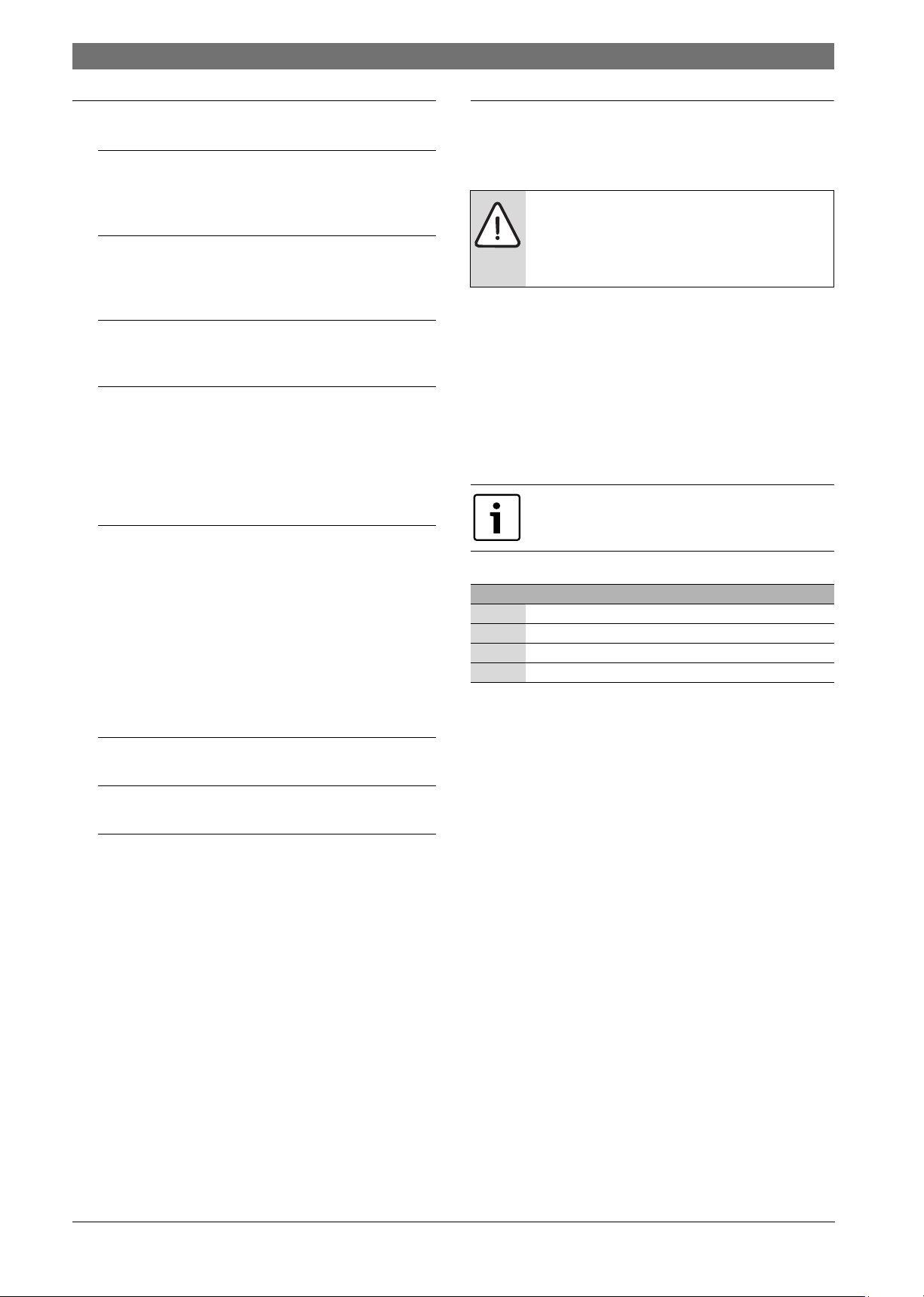
Internal unit AWMS/AWMSS
If the external heat pump is combined with the AWM indoor unit,
together they constitute a complete heating and DHW system as the
indoor unit contains a DHW cylinder. The changeover between heating
and DHW is effected by an internal 3-way valve. The integrated electric
booster heater in the indoor unit is started if required.
Fig. 1 Heat pump for outdoor unit, indoor unit AWMS/AWMSS with integrated DHW cylinder and electric booster heater
Compress 3000 AW6 720 818 009 (2015/07)
Page 5
Overview of system | 5
6 720 814 470-05.1l
VOGEL&NOOT
CLIMATE CONTROL SYSTEMS
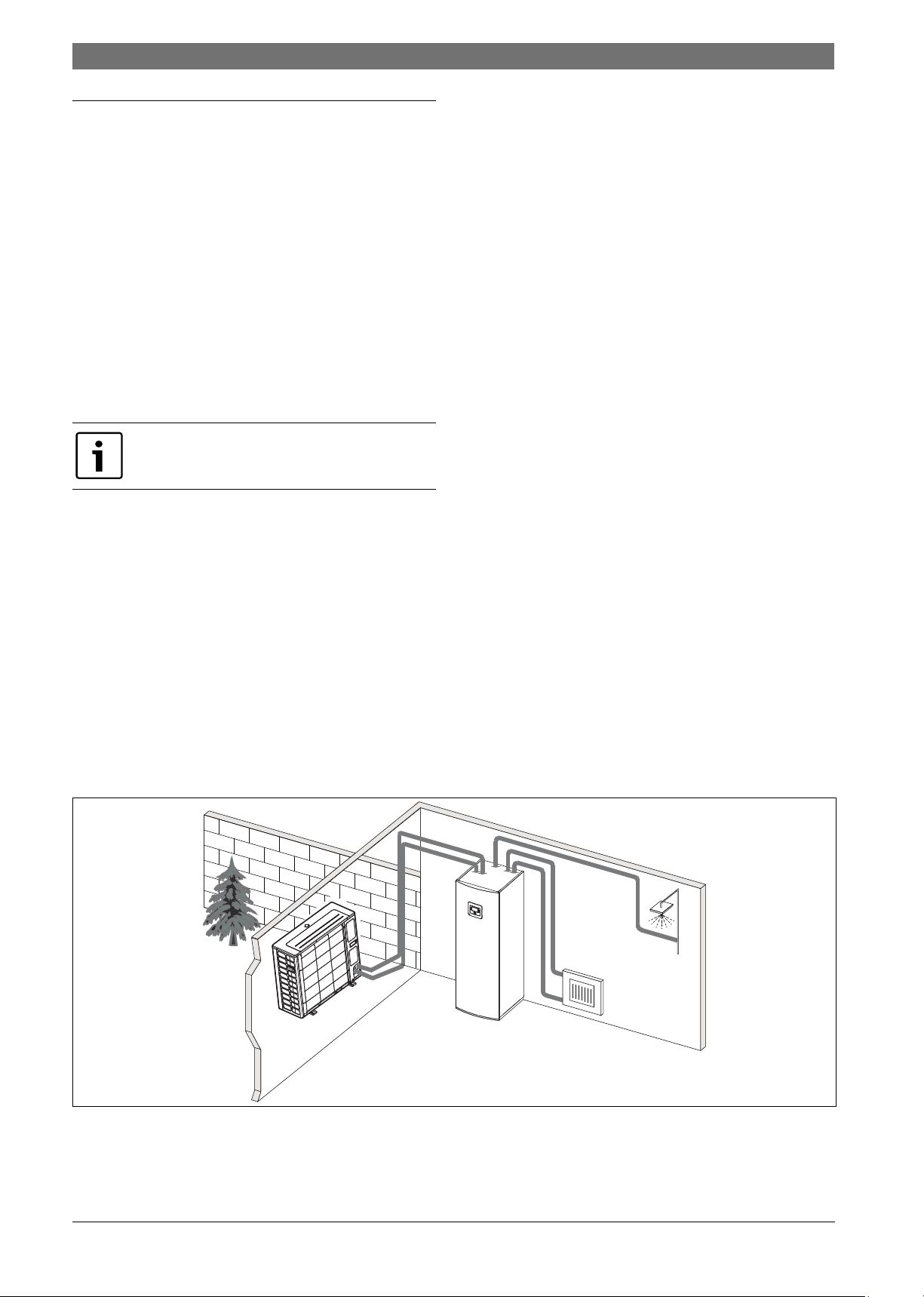
Indoor unit AWES
If the outdoor unit is combined with the indoor unit AWE and DHW is also
to be produced via the heat pump, an external DHW cylinder must be
connected. The changeover between heating and DHW is then effected
by an external 3-way valve. The integrated electric booster heater in the
indoor unit is started if required.
Fig. 2 Heat pump for outdoor unit, indoor unit AWE with electric booster heater and external DHW cylinder
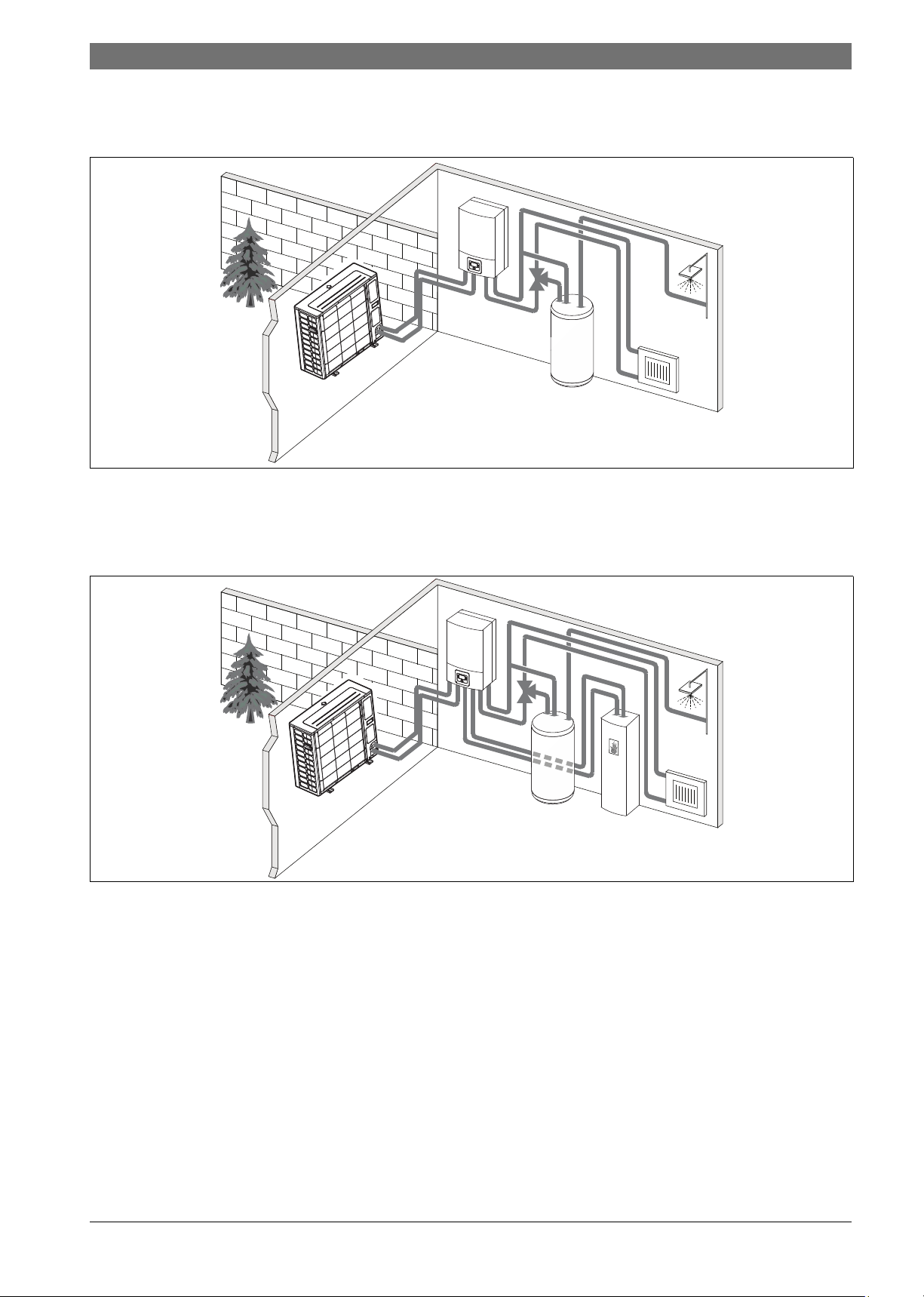
AWBS
If the outdoor unit is combined with the indoor unit AWB and DHW is also
to be produced via the heat pump, an external DHW cylinder must be
by an external 3-way valve. The indoor unit is equipped with a mixe r. This
controls the heat from the external auxiliary heater which can be started
from the indoor unit if required.
connected. The changeover between heating and DHW is then effected
6 720 814 470-04.1l
Fig. 3 Heat pump for outdoor unit, indoor unit AWB without electric booster heater, external DHW cylinder and external auxiliary heater
6 720 818 009 (2015/07)Compress 3000 AW
Page 6
6 | Overview of the most frequently used functions
fav
menu
info
VOGEL&NOOT
CLIMATE CONTROL SYSTEMS
4 Overview of the most frequently used functions
The user manual for the user interface contains a
comprehensive description of all functions and settings.
3
2
fav
1
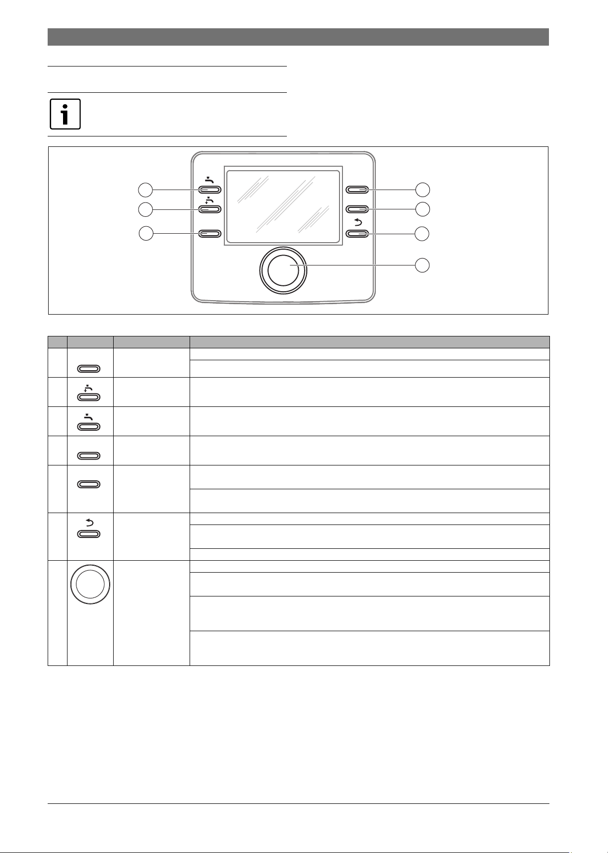
Fig. 4 Control elements
menu
4
info
5
6
7
6 720 810 300-01.1O
Item Element Designation Explanation
1 fav key ▶ Press to call up the favourite functions for heating circuit 1.
▶ Hold down to adjust the favourites menu to individual requirements.
2 extra DHW key ▶ Press to activate the extra-hot DHW function.
3 DHW key ▶ Press to select the DHW operating mode.
4 menu button ▶ Press to open the main menu.
5 Info key If a menu is open:
▶ Press to call up more information about the current selection.
If the standard display is active:
▶ Press to open the info menu.
6 Back key ▶ Press to return to the higher menu level or discard a changed value.
If the need for a service or a fault is displayed:
▶ Press to switch between standard display and fault display.
▶ Hold to switch from a menu to the standard display.
7 Control knob ▶ Turn to change a setting value (e. g. temperature) or select from among the menus or menu items.
If the lighting is switched off:
▶ Press to switch the lighting on.
If the lighting is switched on:
▶ Press to open a selected menu or menu item, confirm a set value (e.g. temperature) or a message or to close a pop-
up window.
If the standard display is active:
▶ Press to activate the input field for selecting the heating circuit in the standard display (only systems with at least
two heating circuits).
Table 2 Control elements
Compress 3000 AW6 720 818 009 (2015/07)
Page 7
Overview of the most frequently used functions | 7
6 720 812 775-05.1O
6 720 811 136-08.1O
6 720 811 136-10.1O
VOGEL&NOOT
CLIMATE CONTROL SYSTEMS
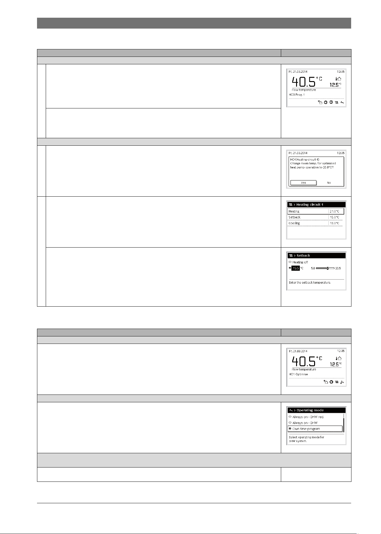
4.1 Changing the room temperature
Operating the appliance Result
If it is too cold or too warm for you today: Change the room temperature temporarily
Changing the room temperature until the next switching time
▶ Turn the selector to set the required room temperature.
The corresponding time slot is displayed in grey in the time program bar chart.
▶ Wait a few seconds or press the selector.
The user interface operates with the modified setting. The change applies until the next switching time in your heating
system time program is reached. After this, the time program settings are restored.
Undoing a temperature change
▶ Turn the selector until the corresponding time slot turns back to black in the time program bar chart and press the
selector.
The change is undone.
Automatic mode
If it is permanently too cold or too hot for you: set the required room temperature (e.g. for heating and setback mode)
▶ Activate optimised operation ( Chapter 4.3).
▶ Wait a few seconds or press the selector to close the pop-up window.
▶ Turn the selector to set the required room temperature.
▶ Wait a few seconds or press the selector. Press the selector to confirm the change in the pop-up window (or press the
back key to discard the change).
The room temperature that is currently valid is shown in a pop-up window in the lower part of the display.
The user interface operates with the modified settings.
Optimised operation
▶ Press the menu key to open the main menu.
▶ Press the selector to open the Heating/Cooling menu.
▶ Turn the selector to highlight the Temperature settings menu.
▶ Press the selector to open the menu.
▶ If two or more heating circuits are installed, turn the selector to highlight Heating circuit 1, 2, 3 or 4 and press the
selector.
▶ Turn the selector to mark Heating, Setback, Elevate or Cooling.
▶ Press the control knob.
▶ Turn the selector and press it to activate the required setting, e.g. for setback mode.
If the temperature control is activated:
▶ Turn and press the selector to set the temperature. The limits of the setting values for the temperatures are determined by
the settings for the other operating mode in each case.
The user interface operates with the modified settings. The settings are applied to all time programs for the heating
system (if two or more heating circuits are installed, it is only applied in the selected heating circuit).
Automatic mode
Table 3 Room temperature
6 720 812 775-06.1O
6 720 811 136-07.1O
4.2 DHW settings
Operating the appliance Result
If you need hot water outside of the times set in the time program: Activate extra DHW (= immediate DHW function).
▶ Press the extra DHW key.
DHW heating is active immediately with the set temperature and for the set duration. After a few seconds, the symbol for extra
DHW will be displayed in the information graphic.
To deactivate the extra DHW function before the end of the set duration:
▶ Press the extra DHW key again.
If the DHW is too cold or too hot for you: Change the DHW heating operating mode
▶ Press the DHW key.
The user interface displays the pick list for DHW heating.
▶ Turn the selector to highlight the required operating mode.
▶ Press the control knob.
The user interface operates with the modified settings. Your contractor can set the temperatures for the DHW and DHW
reduced operating modes.
To prevent the settings for the programming unit from being modified inadvertently:
Activate or deactivate button lock
▶ Press and hold down the DHW key and the selector for a few seconds to activate or deactivate the key block.
When the key lock is enabled, the key symbol appears in the display ( Fig. 4 [5], page 6).
Table 4 More settings
6 720 812 775-09.1O
6 720 818 009 (2015/07)Compress 3000 AW
Page 8
8 | Overview of the most frequently used functions
6 720 811 136-15.1O
VOGEL&NOOT
CLIMATE CONTROL SYSTEMS
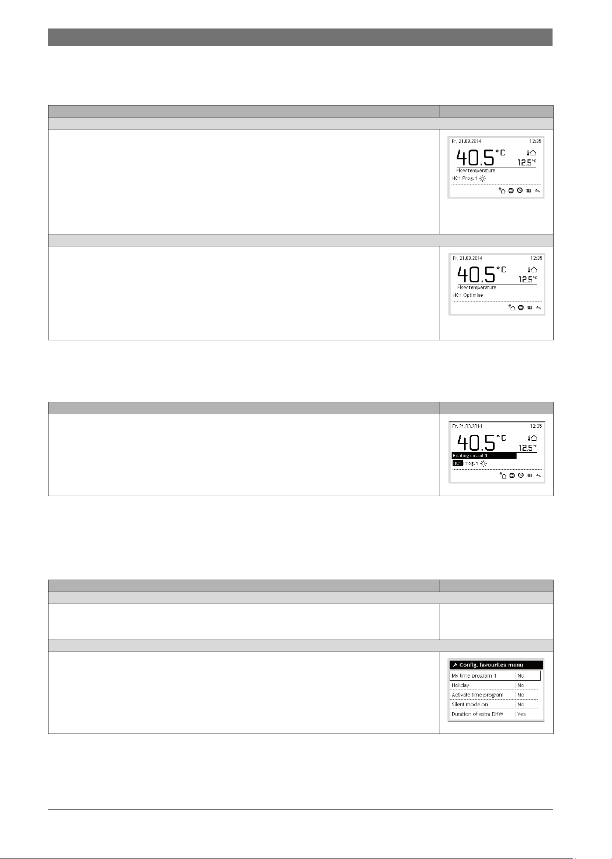
4.3 Setting the operating mode
Optimised operation is enabled by default, as this operating mode
ensures maximum efficiency of the heat pump.
Operating the appliance Result
To activate automatic mode (by taking account of the time program),
▶ Press the menu key to open the main menu.
▶ Press the selector to open the Heating/Cooling menu.
▶ Press the selector to open the Operating mode menu.
▶ If two or more heating circuits are installed, turn the selector to highlight Heating circuit 1, 2, 3 or 4 and press the selector.
▶ Turn the selector to highlight Auto and press the selector.
▶ Press and hold the Back key to return to the standard display.
All temperatures set in the currently valid time program for the heating system are show n in a pop-up window in the lower part
of the display. The currently valid temperature flashes.
The user interface controls the room temperature according to the active time program for the heating system.
To activate optimised operation (without time program)
▶ Press the menu key to open the main menu.
▶ Press the selector to open the Heating/Cooling menu.
▶ Press the selector to open the Operating mode menu.
▶ If two or more heating circuits are installed, turn the selector to highlight Heating circuit 1, 2, 3 or 4 and press the selector.
▶ Turn the selector to highlight Optimise and press the selector.
▶ Press and hold the Back key to return to the standard display.
The required room temperature is shown in a pop-up window in the lower part of the display. The user interface will now
constantly maintain the required room temperature.
Table 5 Getting started – Activating operating modes
6 720 812 775-03.1O
6 720 812 775-04.1O
4.4 Selecting a heating circuit for the standard display
The standard display only ever shows data for a single heating circuit. If
two or more heating circuits are installed, a setting can be made to
Operating the appliance Result
▶ When the lighting is turned on, press the selector.
The number, operating mode and if applicable the name of the heating circuit that is currently selected are shown in the lower
part of the display.
▶ Turn the selector to select a heating circuit.
Only heating circuits that exist in the system are displayed for selection.
▶ Wait a few seconds or press the selector.
The standard display refers to the heating circuit selected.
Table 6 Overview – Standard display of heating circuit
determine which heating circuit the data in the standard display relates
to.
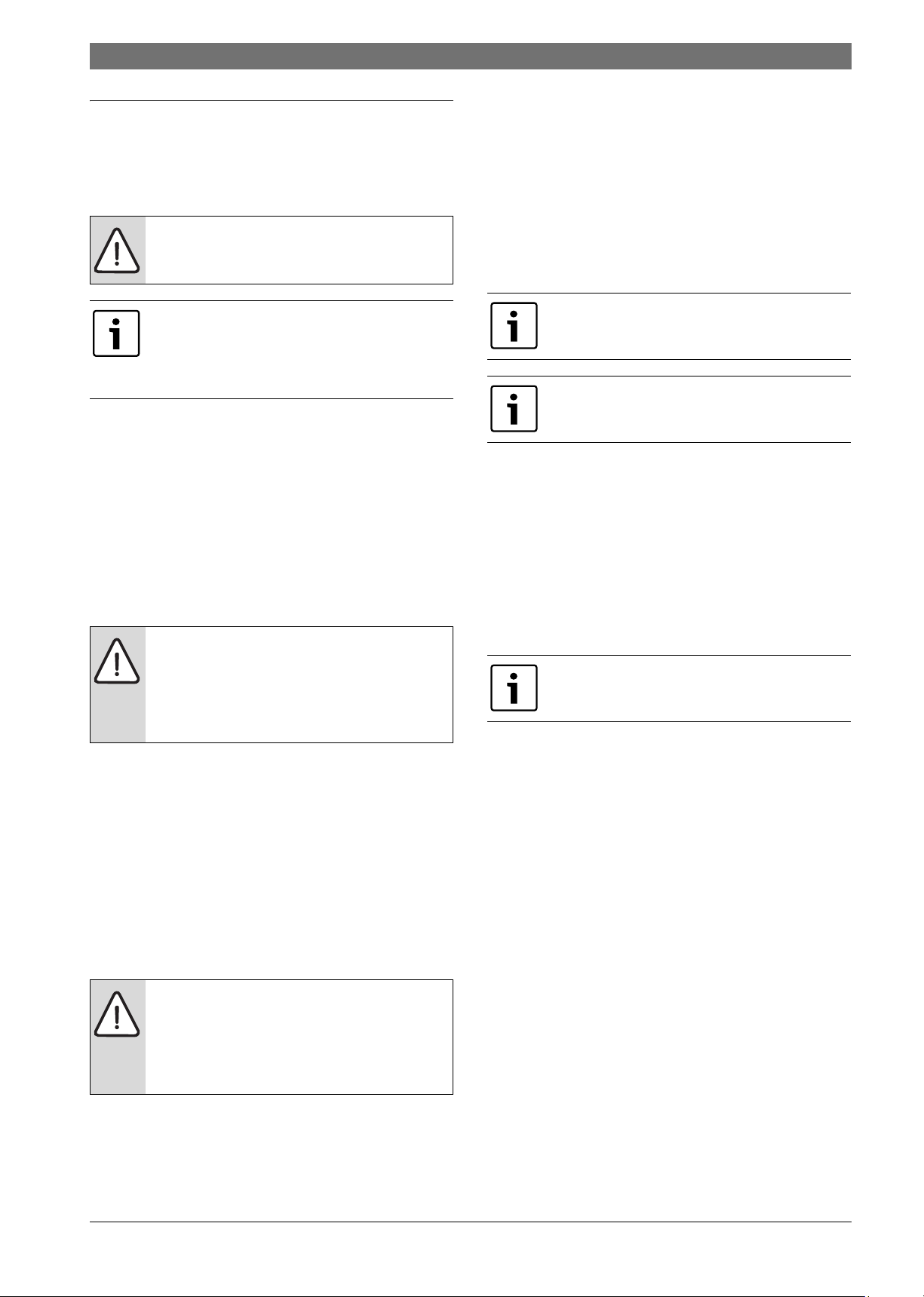
4.5 Favourite functions
Via the fav key you have direct access to often used functions for heating
circuit 1. The first pressing of the fav key opens the menu for configuring
the favourites menu. There you can add your personal favourites and if
necessary later adapt the favourites menu to your requirements.
Operating the appliance Result
To access a favourite function: Open the favourites menu
▶ Press the fav key to open the Favourites menu.
▶ Turn the selector and press to select a favourite function.
▶ Change the settings (procedure is the same as when making a setting in the main menu).
To adapt the list of favourites to meet your requirements: Select favourite functions
▶ Press and hold down the fav key until the menu for configuring the favourites menu is displayed.
▶ Turn and press the selector to select a function (Yes) or to cancel your selection (No).
The changes are effective immediately.
▶ Press the Back key to close the menu.
The function of the fav key is independent of the heating circuit
displayed in the standard display. Settings changes via the favourites
menu always apply only to heating circuit 1.
6 720 812 775-02.2O
Table 7 Favourite functions
Compress 3000 AW6 720 818 009 (2015/07)
Page 9
Maintenance | 9
VOGEL&NOOT
CLIMATE CONTROL SYSTEMS
5 Maintenance
The heat pump requires a minimum of maintenance, however, some
servicing is still required to get optimal performance from your heat
pump. Check the following items a few times per year:
• Remove soiling and foliage at the evaporator and casing
DANGER: The heat pump is connected to high current.
▶ Break the power supply before rectifying.
Damage to system due to use of unsuitable cleaning
agents!
▶ Do not use acidic or alkaline cleaning agents or
cleaning agents containing chlorine or abrasive
products.
5.1 Remove dirt and leaves
▶ Use a brush to remove the dirt and leaves from the heat pump.
5.2 Protective covers
Over time dust and other dirt will collect on the heat pump.
▶ If required, clean the outside with a damp cloth.
▶ Repair cracks and damage at the casing with anti-corrosion paint.
▶ Car wax can be applied to protect the paint.
5.6 Leakage tests
In accordance with current EU legislation (the F-gas regulation, EC
Regulation No 817/2014 which came into effect on 1 January 2015),
Operators of equipment that contains fluorinated greenhouse gases in
quantities of 5 tonnes of CO
foams shall ensure that the equipment is checked for leaks.
In contrast, devices that contain less than 3 kg fluorinated greenhouse
gases are not subject to tightness testing until 31 December 2016.
▶ Contact your installer.
2
equivalent or more and not contained in
5.7 Checking the safety valves
The safety valve should be checked by a qualified
engineer - usually as part of an annual service visit.
Water can drip out of the opening of the pressure relief
valve. The opening of the pressure relief valve (outlet)
must not be sealed under any circumstances.
▶ The pressure relief valve should only drip once the maximum
permissible pressure in the heating system has been exceeded. If the
pressure relief valve still drips at pressures below 2 bar, please
consult the principal contractor of the system.
▶ Make sure that the liquid emerging from the pressure relief valve is
visibly discharged into the drain.
5.3 Evaporator
Wash off any layers of e.g. dust or dirt deposited on the surface of the
evaporator.
WARNING: The thin aluminium fins are fragile and can
be damaged if careless. Never wipe the delicate fins with
a cloth.
▶ Use protective gloves to protect your hands from
cuts.
▶ Do not use a too powerful water jet.
Cleaning the evaporator:
▶ Spray cleaning agent on the evaporator fins on the back of the heat
pump.
▶ Rinse off coatings and cleaning agent with water.
5.4 Snow and ice
In certain geographical regions or during periods of heavy snow, snow
can get stuck on the back and the roof of the heat pump. To prevent
subsequent formation of ice, remove the snow.
▶ Clear the snow off the roof.
▶ Warm water can be used to rinse off the ice.
5.5 Moisture
NOTICE: If moisture frequently forms near the indoor
unit or the fan convectors in cooling mode, this could
mean that the condensation insulation is defective.
▶ If moisture forms in the vicinity of components of the
heating system, switch the heat pump off and consult
the system installer.
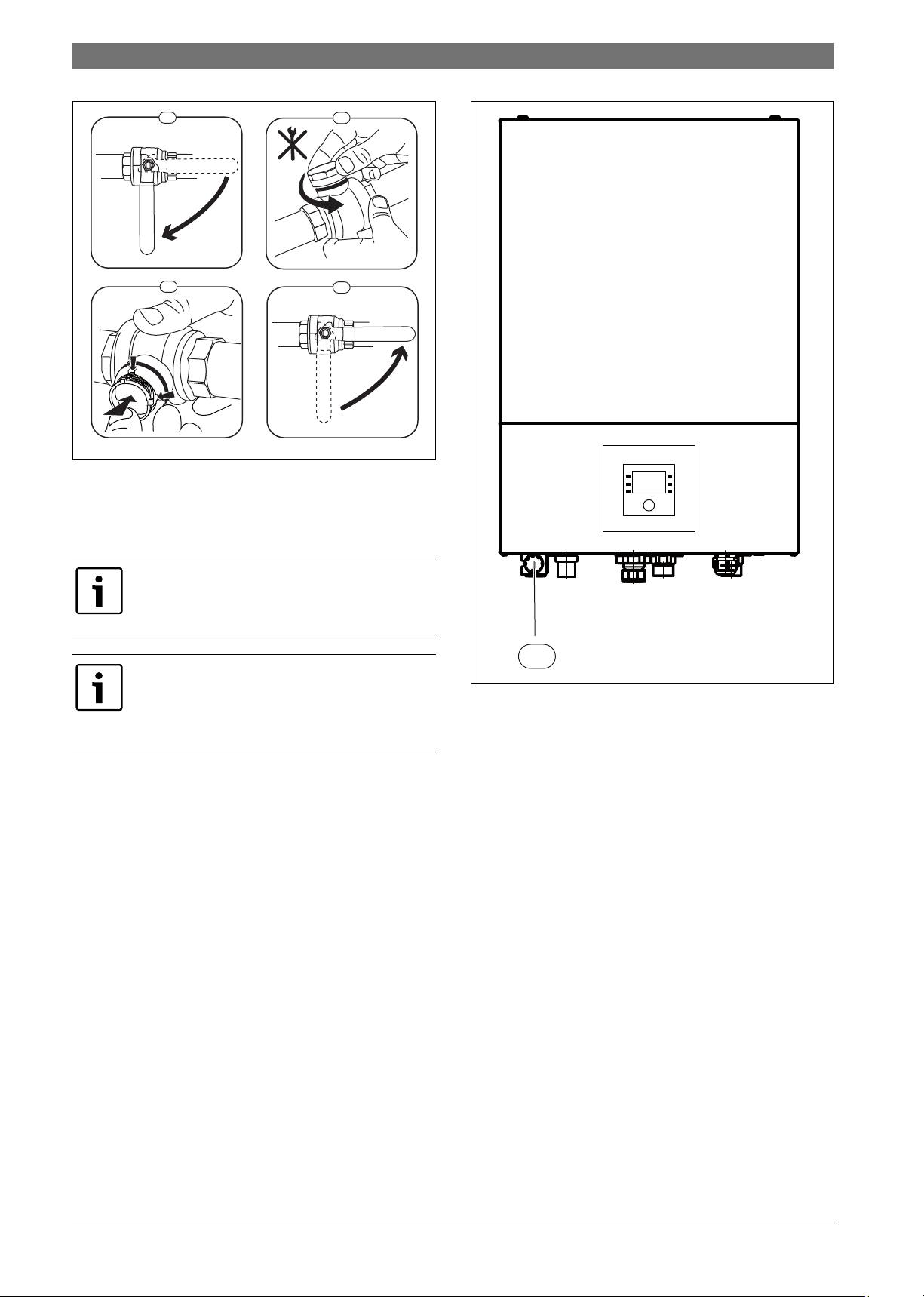
5.8 Particle filter
Check particle filter
The filter prevents contamination from the heating system from entering
the heat pump. Clogged filters can lead to faults.
The system does not have to be drained in order to clean
the filter. The filter is normally integrated into the shutoff valve and should be installed in the heating return.
Cleaning the strainer
▶ Close valve (1).
▶ Unscrew the cap (by hand) (2).
▶ Remove the strainer and clean under running water.
▶ Reinstall the strainer. To ensure the installation is performed
correctly, make sure the guide lugs fit into the recesses in the valve
(3).
Moisture can form under the heat pump (outside) due to condensate not
falling into the condensation catch pan. This is normal and no special
action is required.
6 720 818 009 (2015/07)Compress 3000 AW
Page 10
10 | Maintenance
1.
2.
2.
1.
1
2
3
4
6 720 805 915-01.1I
1
6 720 810 353-11.1I
VOGEL&NOOT
CLIMATE CONTROL SYSTEMS
Fig. 5 Filter version without circlip
▶ Screw cap back on (by hand).
▶ Open valve (4).
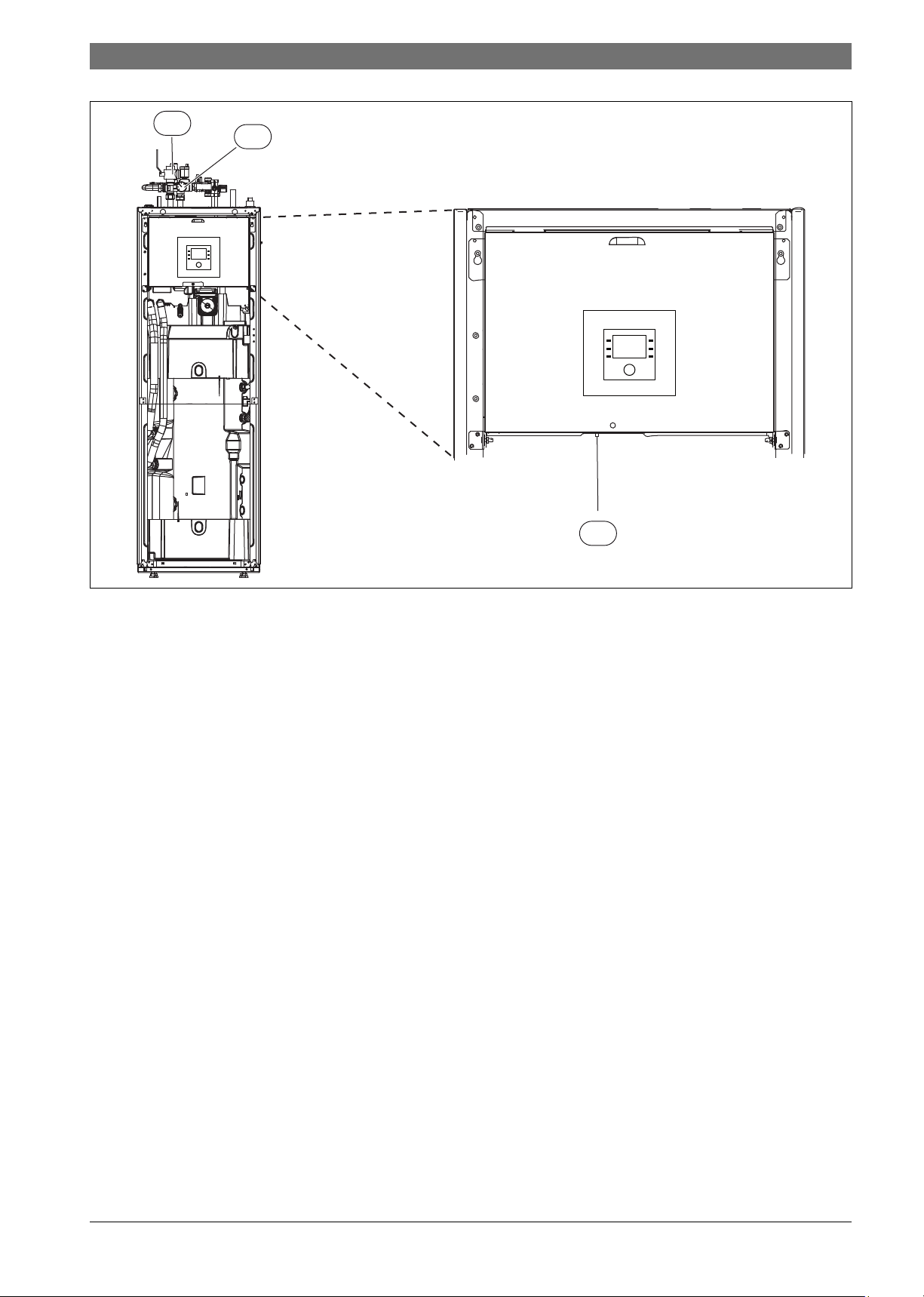
5.9 Pressure switch and overheating protection
The pressure regulator and overheating protection are
only installed in the indoor unit with integrated electric
booster heater. If the overheating protection has been
triggered, it must be reset manually.
The pressure switch and overheating protection are
connected in series. Alarms or mes sages triggered at the
user interface indicate either that the system pressure is
too low, or that the temperature at the electric booster
heater is too high.
If the pressure switch has been triggered, it is automatically reset as
soon as the system pressure reaches the correct value.
▶ Check the pressure at the pressure gauge.
▶ If the pressure is less than 0.5 bar, increase the pressure slowly to
max. 2 bar by filling with water via the fill valve.
▶ If you have any questions about the procedure, consult the installer
of the system.
Resetting the overheating protection at the indoor unit AWMS/AWMS
solar:
▶ Pull out the front panel at the bottom and pull up and off.
▶ Firmly push the button at the overheating protection.
▶ Reinsert the front panel
Resetting the overheating protection at the indoor unit AWES:
▶ Consult the system installer.
Fig. 6 Indoor unit AWES
[1] Pressure gauge
Compress 3000 AW6 720 818 009 (2015/07)
Page 11
Maintenance | 11
VOGEL&NOOT
CLIMATE CONTROL SYSTEMS
2
3
1
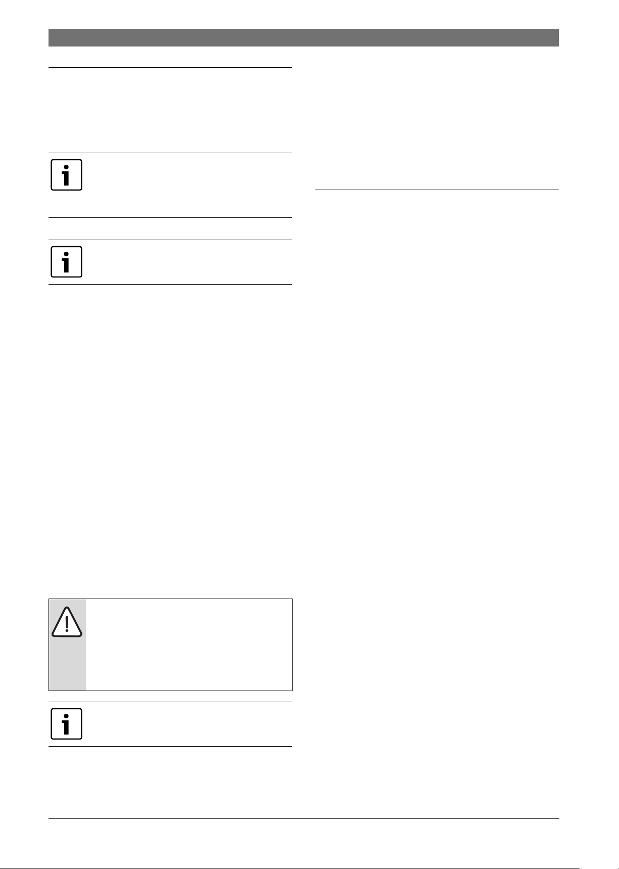
Fig. 7 Indoor unit AWMS/AWM solar
[1] Resetting the overheating protection
[2] Particle filter
[3] Pressure gauge
6 720 810 353-10.1I
6 720 818 009 (2015/07)Compress 3000 AW
Page 12
12 | Internet connection via integrated IP module
VOGEL&NOOT
CLIMATE CONTROL SYSTEMS
6 Internet connection via integrated IP module
The indoor unit is equipped with an integrated IP module . The indoor unit
and heat pump can be controlled and monitored via a mobile unit using
this IP module. The module is used as an interface between the heating
system and a network (LAN) and also makes the SmartGrid function
possible.
Login data for the IP module
Manuf. no.:__ __ __ __ - __ __ __ __ __ __ __ __ __ - __ __ __ __ __ __ __ __ __ __
Login name: ___ ___ ___ ___ ___ ___ ___ ___ ___
Password: __ __ __ __ - __ __ __ __ - __ __ __ __ - __ __ __ __
To be able to use the full scope of functions, Internet
access and a router with unassigned RJ45 output are
required. This can lead to additional costs. The Bosch
connect app is required to control the system using a
mobile phone and is available free of charge.
Commissioning
Observe the documentation for the router when
commissioning.
The router must be configured as follows:
• DHCP active
• Ports 5222 and 5223 must not be blocked for outgoing
communication.
• Unassigned IP address is available
• Address filtering (MAC filter) adapted to the module.
The following options for commissioning the IP module are available:
• Internet
The IP module automatically obtains an IP address from the router.
The name and address of the target server are stored in the standard
settings of the module. If an internet connection is established, the
module logs onto the server automatically.
• Local network
The module does not have to have Internet access. It can also be used
in a local network. In this case however, the heating system cannot be
accessed through the Internet, and the module software is not
automatically updated.
• App Bosch connect
When starting the app for the first time, you will be asked to enter the
login name and password set at the factory. The login details are
printed on the data plate of the IP module.
•SmartGrid
The indoor unit can communicate with the energy exchange and
modify the operation of the heat pump so that it is at the maximum
output when the price for the power is the most affordable. For more
information see the Bosch website.
Mac: ___ ___ - ___ ___ - ___ ___ - ___ ___ - ___ ___ - ___ ___
7 Environment / disposal
Environmental protection is a fundamental corporate strategy of the
Bosch Group.
The quality of our products, their efficiency and environmental safety
are all of equal importance to us and all environmental protection
legislation and regulations are strictly observed.
We use the best possible technology and materials for protecting the
environment taking into account of economic considerations.
Packaging
We participate in the recycling programmes of the countries in which our
products are sold to ensure optimum recycling.
All of our packaging materials are environmentally friendly and can be
recycled.
Used appliances
Used appliances contain valuable materials that should be recycled.
The various assemblies can be easily dismantled and synthetic materials
are marked accordingly. Assemblies can therefore be sorted by
composition and passed on for recycling or disposal.
NOTICE: If the IP module is replaced, the login details
will be lost!
Individual login details are required for each IP module.
▶ After commissioning, enter the login data in the
▶ Following a replacement, replace with the details of
Alternately, the password can be changed at the user
interface.
corresponding field.
the new IP module.
Compress 3000 AW6 720 818 009 (2015/07)
Page 13

Technical terms
VOGEL&NOOT
CLIMATE CONTROL SYSTEMS
Technical terms | 13
Heat pump
The central heat source. Installed in the open air. Alternative
designation: outdoor unit. Contains the cooling circuit. Heated or cooled
water is routed from the heat pump to the indoor unit.
Indoor unit
Installed in the building and distributes the heat from the heat pump to
the heating system and DHW cylinder. Contains the user interface and
primary pump to the outside to the heat pump.
Heating system
Designation for entire installation, comprising the heat pump, indoor
unit, DHW cylinder, heating system and accessories.
Heating system
Comprises heat source, container, radiators, underfloor heating system
or fan radiators or a combination of these elements if the heating system
is made up of several heating circuits.
Heating circuit
The part of the heating system that distributes the heat throughout the
various rooms. Consists of pipework, pump and radiators, heating hoses
of the underfloor heating system or fan convectors. Only one of the
specified alternatives is possible within a circuit. However, if for
example the heating system is equipped with two circuits, radiators can
be installed in one and an underfloor heating system installed in the
other. Heating circuits can be configured with and without mixers.
Heating circuit without mixer
In a heating circuit without a mixer the temperature in the circuit is
controlled purely by the energy from the heat source.
Heating circuit with mixer
In a heating circuit with mixer, the mixer mixes return water from the
circuit with hot water from the heat source. This allows heating circuits
with mixers to be operated at lower temperatures than the other heating
system, e.g. so that underfloor heating systems that operate at lower
temperatures can be separated from radiators that require higher
temperatures.
Mixing device
The mixer is a valve that mixes colder return water with hot water from
the heat source in order to achieve a specific temperature. The mixer can
be in a heating circuit or in the indoor unit for the external auxiliary
heater.
3-way valve
The 3-way valve distributes thermal energy to the heating circuits or the
DHW cylinder. It has two defined settings so that heating and DHW
heating cannot take place at the same time. This is also the most
effective operating mode as the DHW is always heated to a specific
temperature whereas the heating water temperature is continuously
adapted to the outside temperature in each case.
External auxiliary heater in dual-fuel mode
The external auxiliary heater is a separate heat source which is
connected via pipework to the indoor unit. The heat produced in the
auxiliary heater is controlled via a mixer. It is therefore also referred to as
an auxiliary heater with mixer or boiler. The user interface controls the
connection and shutdown of the auxiliary heater according to the
existing heat energy demand. Heat sources are electric, oil-fired or gasfired boilers.
Primary circuit
The part of the heating system that transports the heat from the heat
pump to the indoor unit.
Cooling circuit
The main part of the heat pump that recovers energy from the outdoor
air and transfers this as heat to the primary circuit. Consists of
evaporator, compressor, condenser and expansion valve. The
refrigerant circulates in the cooling circuit.
Evaporator
Heat exchanger between air and refrigerant. The energy from the air that
is drawn in through the evaporator causes the refrigerant to boil and turn
to gas.
Comp
Moves the refrigerant through the cooling circuit from the evaporator to
the condenser. Increases the pressure of the gaseous refrigerant. The
temperature also increases as the pressure increases.
Condenser
Heat exchanger between refrigerant in cooling circuit and water in the
heat transfer medium circuit. During the heat transfer, the temperature
of the refrigerant falls as it transfers to the liquid aggregation state.
Expansion Valve
Reduces the pressure of the refrigerant after it is discharged from the
condenser. The refrigerant is then routed back to the evaporator where
the process starts again.
Transformer
Located in the heat pump and allows the speed of the compressor to be
controlled based on the heat energy demand.
Setback phase
A time slot during automatic mode, with Setback operating mode.
Automatic mode
The heating system is heating in accordance with the time program and
an automatic changeover takes place between operating modes.
Mode
The operating modes for heating are: Heating and Setback. They are
depicted by the symbols and .
Operating modes for DHW heating are:DHW, DHW reduced and Off.
An adjustable temperature is assigned to each operating mode (except
for Off).
Frost protection
Depending on the selected frost protection, the heat pump will turn on
when the outside and/or room temperature reaches below a certain set
threshold. Frost protection prevents the heating system from freezing
up.
Required room temperature (also desired or set temperature/set
room temp.)
The room temperature to be achieved by the heating system. It can be
set individually.
Default setting
Values permanently saved in the programming unit (e.g. complete time
programs) that are available at any time and that can be reinstated
according to demand.
Heating phase
A time slot during automatic mode, with Heating operating mode.
Child lock
Settings in the standard display and in the menu can only be changed if
the child lock (key lock) is switched off ( page 7).
6 720 818 009 (2015/07)Compress 3000 AW
Page 14

14 | Technical terms
VOGEL&NOOT
CLIMATE CONTROL SYSTEMS
Mixer
Assembly that automatically ensures that hot water can be drawn from
the taps at a temperature no higher than the temperature set on the
mixer.
Optimised operation
In optimised operation, automatic mode (the heating system time
program) is not active and the home is heated constantly to the
temperature set for optimised operation.
Reference room
The reference room is the room in the home where a room unit has been
installed. The room temperature in this room acts as the control variable
for the assigned heating circuit.
Switching time
A certain time at which the heating system starts to heat or hot water is
produced, for example. A switching time is a component of a time
program.
Temperature of an operating mode
A temperature that is assigned to an operating mode. The temperature is
adjustable. See the explanations on operating mode.
Flow temperature
Temperature at which the heated water flows in the central heating
system from the heat source to the heating surfaces in the rooms.
Water heater
A water heater stores large volumes of heated tap DHW. Thereby,
sufficient DHW is available at the draw-off points (e.g. taps). This is a
prerequisite for longer hot shower.
Time program for the heating system
This time program ensures automatic changeover between operating
modes at defined switching times.
Compress 3000 AW6 720 818 009 (2015/07)
Page 15

Notes
| 15
6 720 818 009 (2015/07)Compress 3000 AW
Page 16

CLIMATE CONTROL SYSTEMS
KE KELIT NZ Ltd
0800 4 KEKELIT (0800 4 5353548)
climatecontrol@kekelit.co.nz
www.kekelit.co.nz
 Loading...