

Parking Lot Sensor | PLS
1 | 14
Parking Lot Sensor | PLS
Benutzerhandbuch 1.0.2
Benutzerhandbuch
User manual
Manual de usuario
Manuale utente
Manual do utilizador
Manuel d'installation
Gebruiksaanwijzing
Príručka používateľa
Uživatelská příručka
Felhasználói kézikönyv
Instrukcja użytkowania
Εγχειρίδιο χρήστη

Parking Lot Sensor | PLS
2 | 14
Inhaltsverzeichnis
1 Allgemeine Beschreibung und Verwendungszweck 3
2 Montage und Inbetriebnahme 3
2.1 Installationsvoraussetzungen .............................................................................................................................. 3
2.2 Montage der Sensorbasis ................................................................................................................................... 4
Benötigtes Material zur Installation des Parking Lot Sensors ..................................................................................... 4
Vorbereitung des Parkplatzes ..................................................................................................................................... 4
Installation der Sensorbasis ........................................................................................................................................ 6
2.3 Montage des Sensors ......................................................................................................................................... 8
2.4 Austausch / Entfernen des BOSCH Parking Lot Sensors .................................................................................. 9
2.5 Anlegen und Betreiben des Parking Lot Sensors im Back-End ........................................................................ 10
3 Technische Daten 11
4 Rechtliche Informationen 12
4.1 Entsorgungshinweis gemäß ElektroG und WEEE Richtlinie 2012/19/EU ........................................................ 12
4.2 EU-Konformitätserklärung ................................................................................................................................. 12
4.3 Hinweis für den Transport ................................................................................................................................. 12
4.4 OSS Hinweis ..................................................................................................................................................... 13
Parking Lot Sensor | PLS
3 | 14
1 Allgemeine Beschreibung und Verwendungszweck
Der Parking Lot Sensor PLS mit TPS110 EU Sensorkern dient zur Belegungserkennung von Parkflächen mit
geparkten Fahrzeugen. Der Parking Lot Sensor PLS mit TPS110 EU Sensorkern ist nicht für den Einsatz in
lebenserhaltenden Anwendungen, sicherheitskritischen Anwendungen oder Anwendungen geeignet, in denen eine
Fehlfunktion zu Verletzungen, zum Tod oder schweren Sachschäden führen kann. Verwenden Sie den Parking Lot
Sensor ausschließlich in Verbindung mit den von BCDS freigegebenen Komponenten. Dieses Benutzerhandbuch ist
für den Parking Lot Sensor PLS mit TPS110 EU Sensorkern von BCDS gültig.
2 Montage und Inbetriebnahme
2.1 Installationsvoraussetzungen
Der Kunde muss alle für die Installation und den Betrieb des Produkts einschlägigen Gesetze und Richtlinien einhalten
und, falls erforderlich, die hierfür erforderlichen Genehmigungen einholen. Der Kunde muss geeignete Maßnahmen
ergreifen, um Verletzungen Dritter zu verhindern, indem Dritte beispielsweise über das Produkt stolpern. Das Produkt
sollte deshalb bspw. nicht auf dem Bürgersteig installiert werden.
Stellen Sie vor der Installation der Sensoren sicher, dass die notwendige Infrastruktur ordnungsgemäß funktioniert –
achten Sie darauf, dass die Gateways eingeschaltet sind, eine stabile Internetverbindung besteht und sie sich mit dem
Back-End verbunden haben. Das Back-End sowie die zugehörige Management Software müssen funktional sein.
Stellen Sie weiter sicher, dass alle benötigten Komponenten (siehe Abb. 1 Parking Lot Sensor PLS mit TPS110 EU
Sensorkern) sowie Werkzeuge bereitliegen.
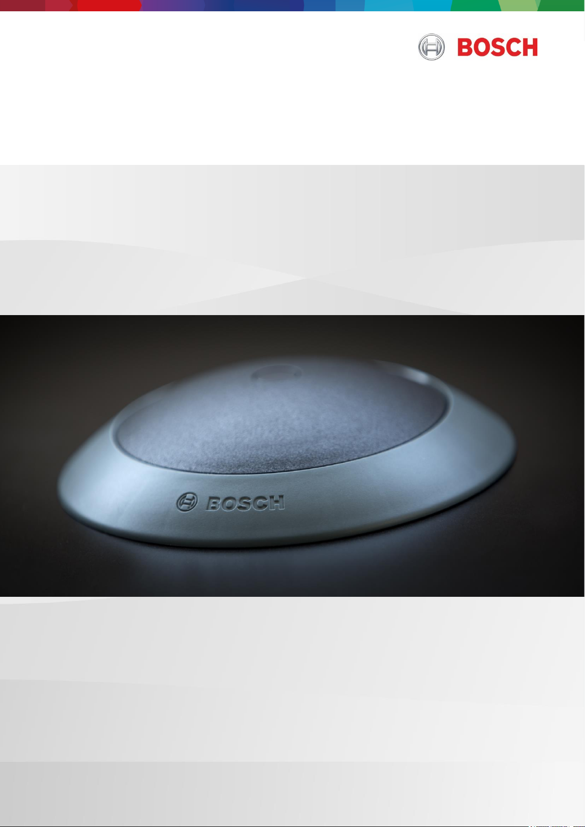
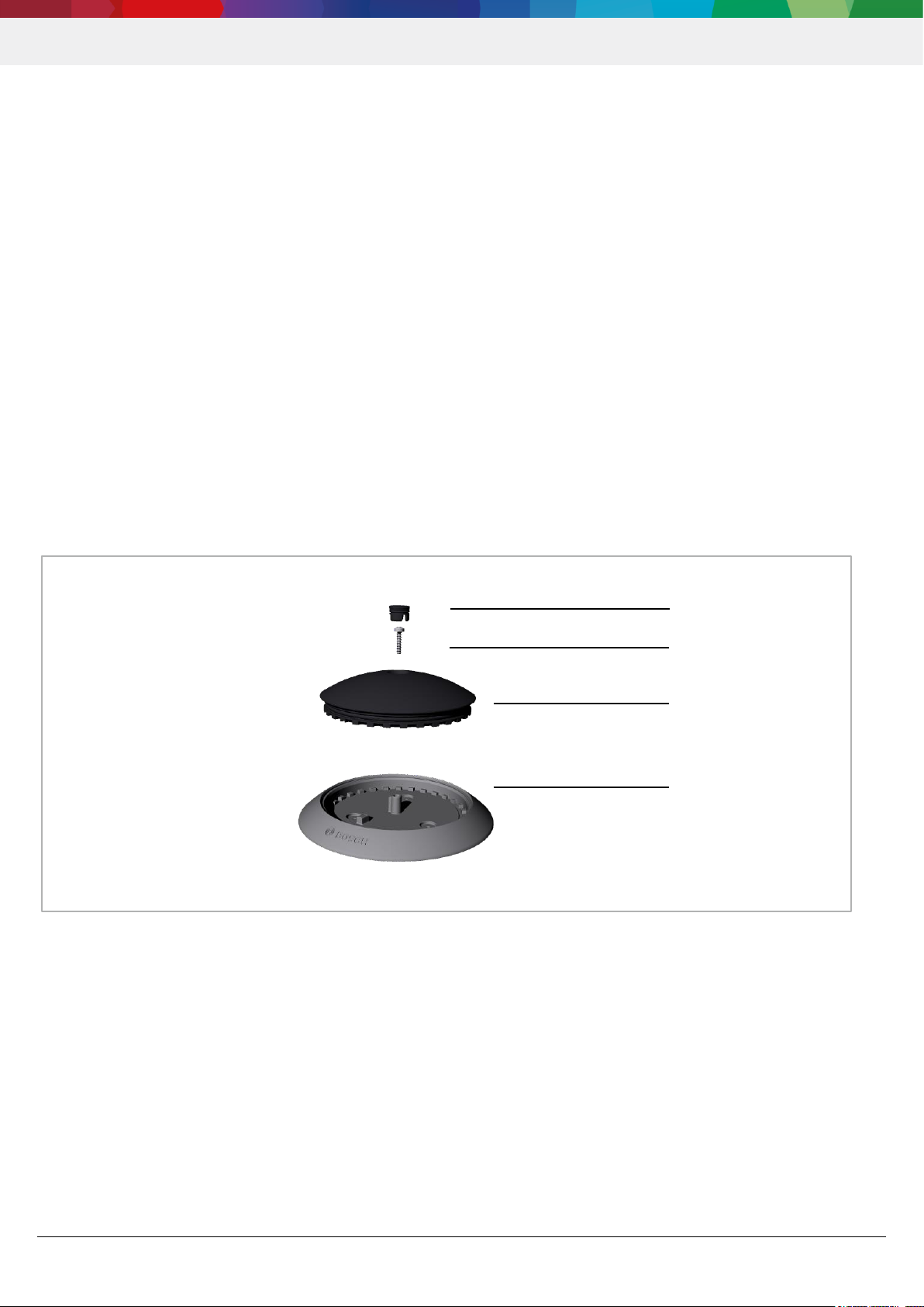
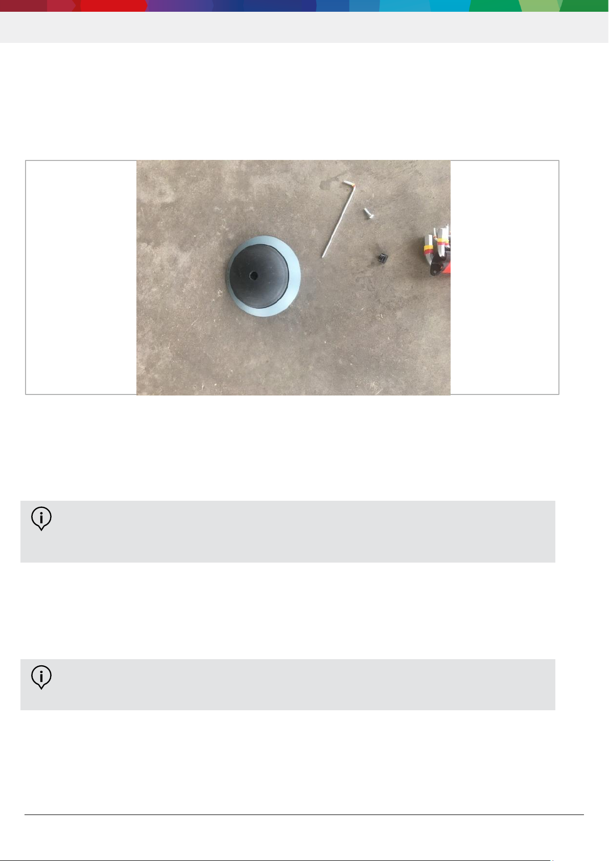
Abbildung 1 Parking Lot Sensor PLS mit TPS110 EU Sensorkern
1 Cap
2 Schraube
4 Base (Sensorbasis)
3 Core (Sensor TPS110 EU)
Parking Lot Sensor | PLS
4 | 14
2.2 Montage der Sensorbasis
Die Sensorbasis wird mit dem Untergrund (z.B. Beton, Asphalt) verklebt. Hierfür empfehlen wir einen
Zweikomponentenklebstoff. Mit dem folgenden Klebstoff haben wir bereits gute Erfahrungen gemacht:
DELO®-PUR 9692 (universeller 2k Polyurethanklebstoff verfügbar in 50 ml und 200 ml Kartuschen). Gerne
unterstützen wir Sie bei der Beschaffung. Wir empfehlen, zunächst mehrere Sensorbasen zu verkleben und erst dann
die Sensoren zu montieren.
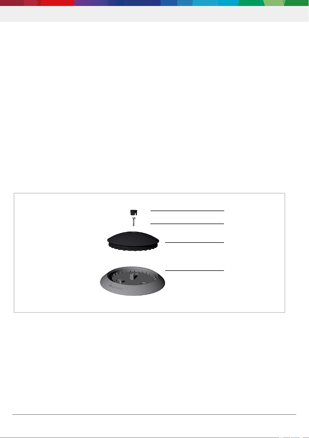
Benötigtes Material zur Installation des Parking Lot Sensors
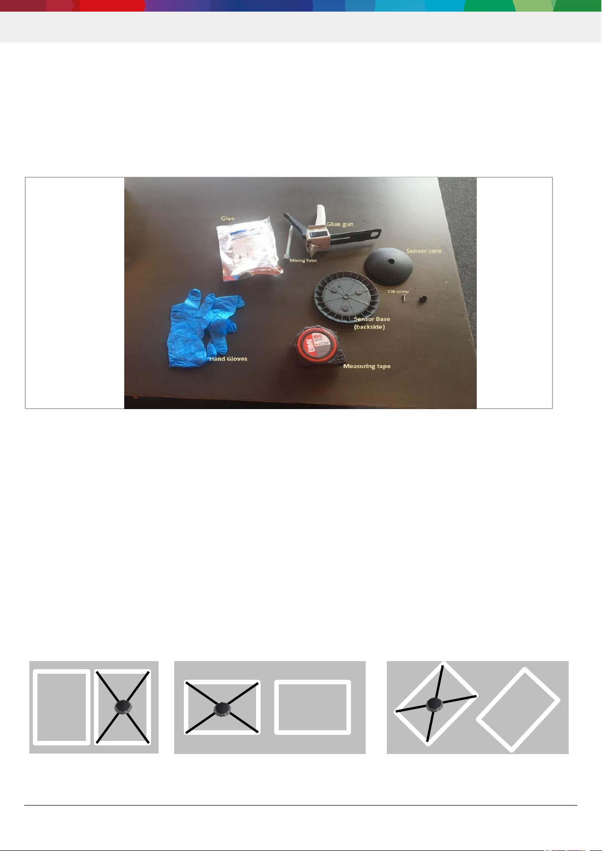
Abbildung 2 Material für Kleben
1 Einmalhandschuhe (Schutz vor Kontakt mit Klebstoff)
2 Zweikomponentenklebstoff
3 Klebepresse (Diese unterscheiden sich je nach Kartuschengröße)
4 Mischspitze
5 Maßband
6 Sensor base (Sensorbasis)
7 Sensor core (Sensor)
8 T20 Schraube
9 Sensor cap (Sensor Verschlusskappe)
Vorbereitung des Parkplatzes
Der Parkplatz muss frei von Schmutz, Staub, Öl, Wasser und weiteren Verunreinigungen sein. Hierzu sollte
mindestens eine besenreine Fläche vorbereitet werden. Es empfiehlt sich jedoch mit einem Hochdruckreiniger und
einem Brenner die Fläche von Verunreinigungen zu befreien.
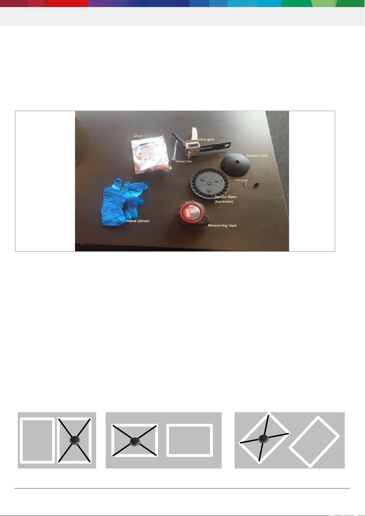
Die Installation muss in der Parkplatzmitte (Schnittpunkt der beiden Diagonalen siehe Abb. 3) des Parkplatzes
stattfinden, um eine optimale Sensorgenauigkeit zu gewährleisten.
Abbildung 3 Bestimmung der Parkplatzmitte
Parking Lot Sensor | PLS
5 | 14
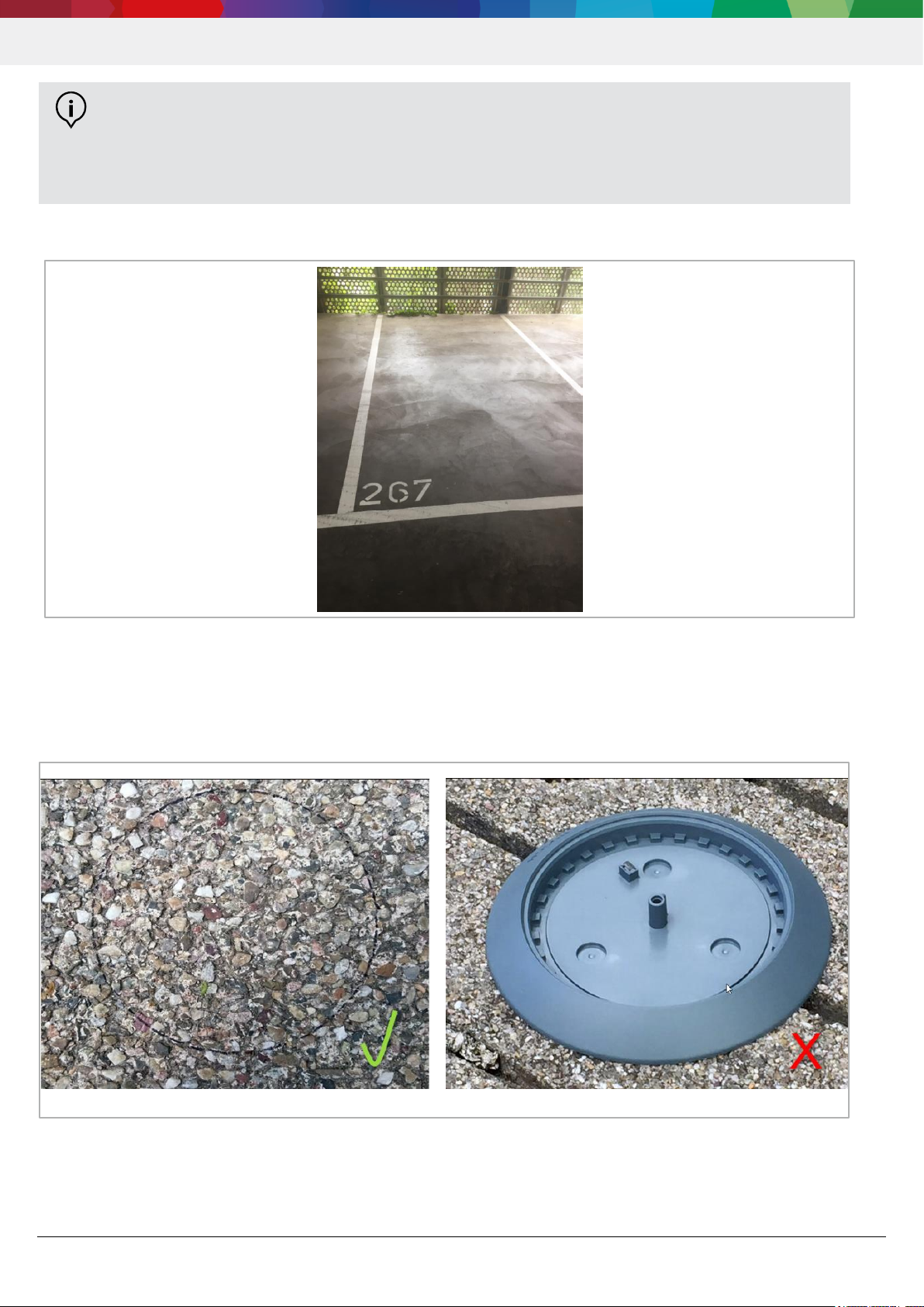
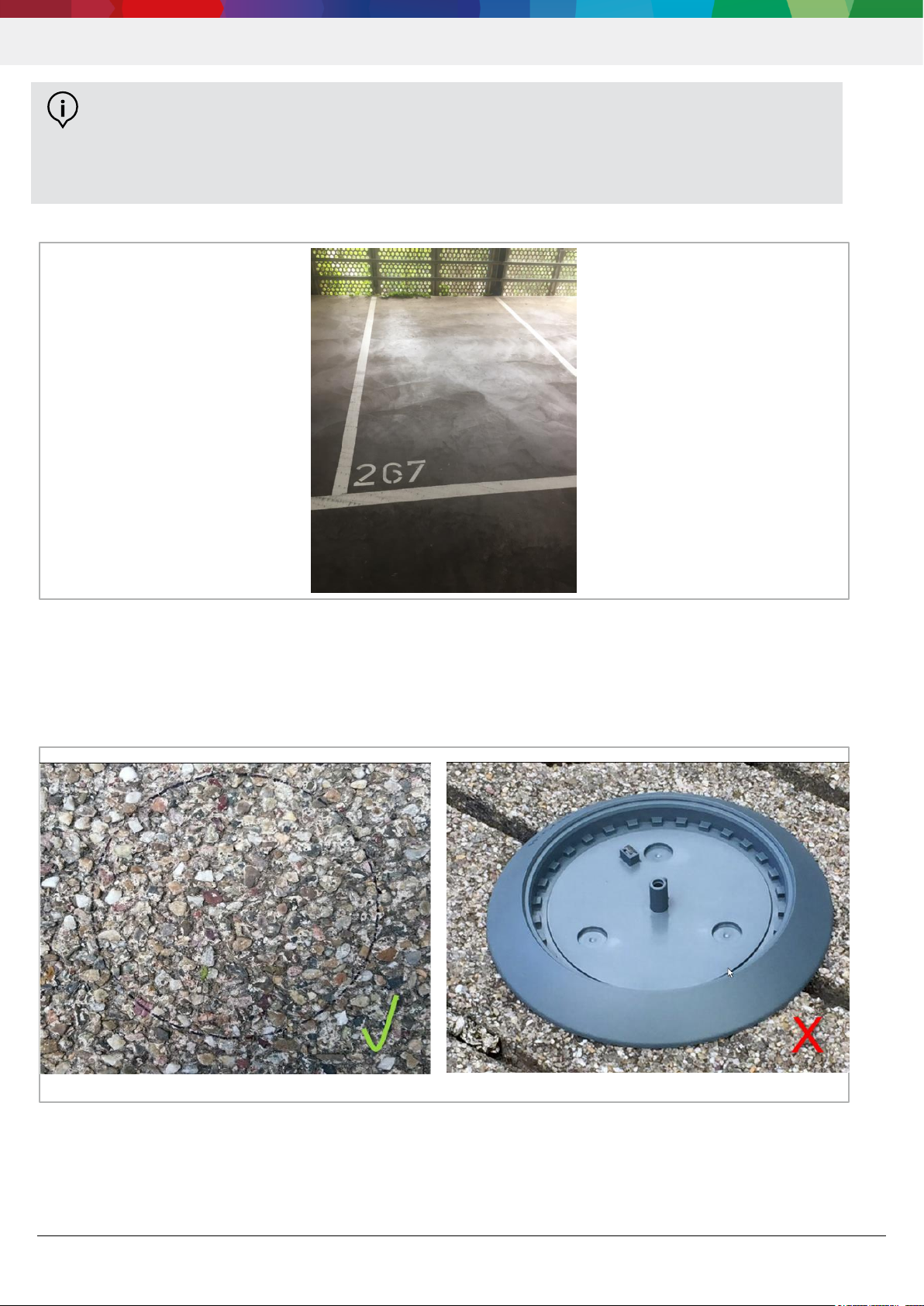
Abbildung 4 Freier Parkplatz für Sensor Installation
Die für die Installation der Sensorbasis vorgesehene Fläche sollte weder Fugen noch Versatz aufweisen, um dem
Klebstoff einen geschlossenen Untergrund zu bieten (siehe Abb. 4 Freier Parkplatz für Sensor Installation). Dies ist für
die Kontaktfläche und die Klebewirkung des Sensors entscheidend.
Abbildung 5 Untergrundbeispiel (unterbrechungsfrei) Abbildung 6 Untergrundbeispiel (Fuge)
INFO:
Für das Kleben bitte die Vorgaben des Klebstoffherstellers beachten (z.B. Temperatur,
Sicherheitshinweise und Arbeitsanweisungen).
Eine Parkplatzreinigung sollte zuvor mit dem Parkplatzbetreiber abgeklärt werden, so dass keine
Ablösung von vorhandenen Beschichtungen durch die Behandlung verursacht wird.
Parking Lot Sensor | PLS
6 | 14
Installation der Sensorbasis
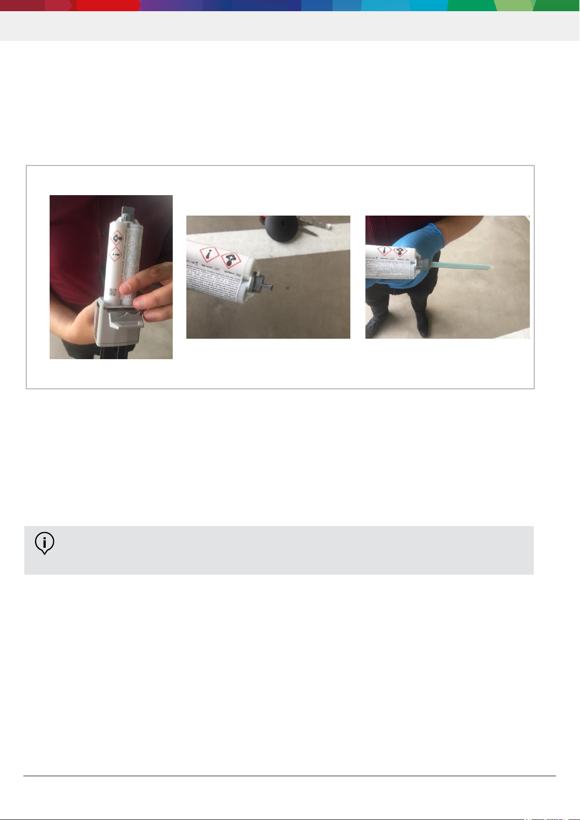
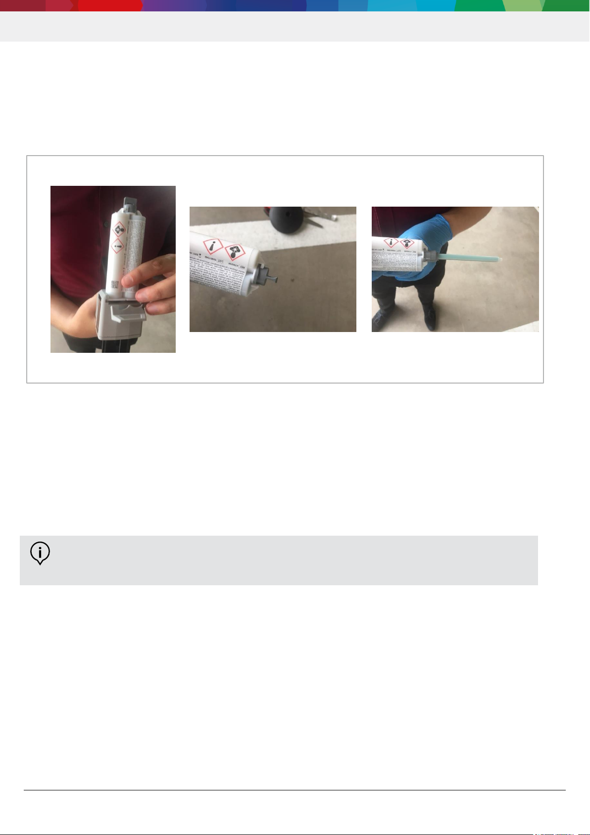
Legen Sie die Klebstoffkartusche in der Klebepistole / Klebepresse ein (Abb. 7 Einlegen der Klebekartusche; im Fall
von DELO®-PUR 9692 ist das Mischverhältnis 1:1, somit muss nicht auf die Orientierung der Kartusche geachtet
werden). Montieren Sie anschließend die Mischspitze an der Kartusche, indem Sie den Verschluss der Kartusche
entfernen (Abb. 8 Verschlusskappe Klebekartusche) und das Mischrohr anbringen (Abb. 9 Mischrohr auf
Klebekartusche; hier Bajonettverschluss).
Abbildung 7 Einlegen der Kartusche Abbildung 8 Verschlusskappe Abbildung 9 Mischrohr
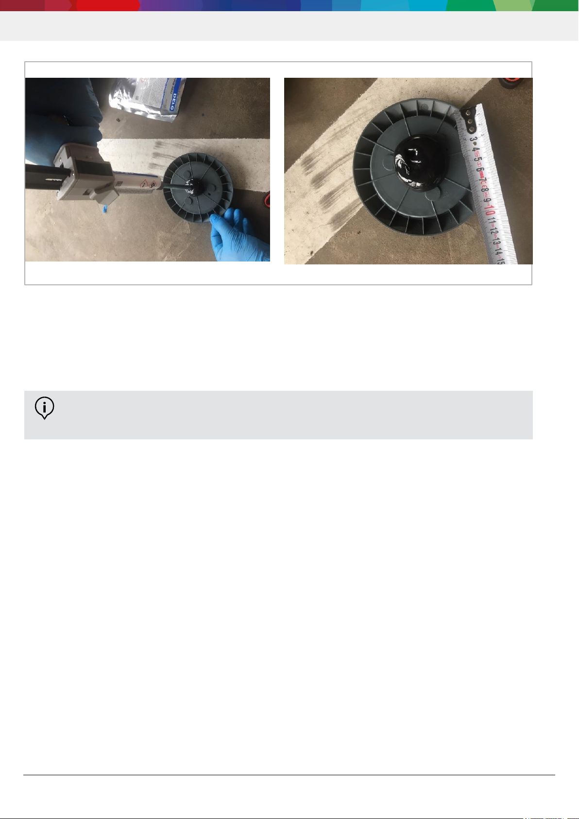
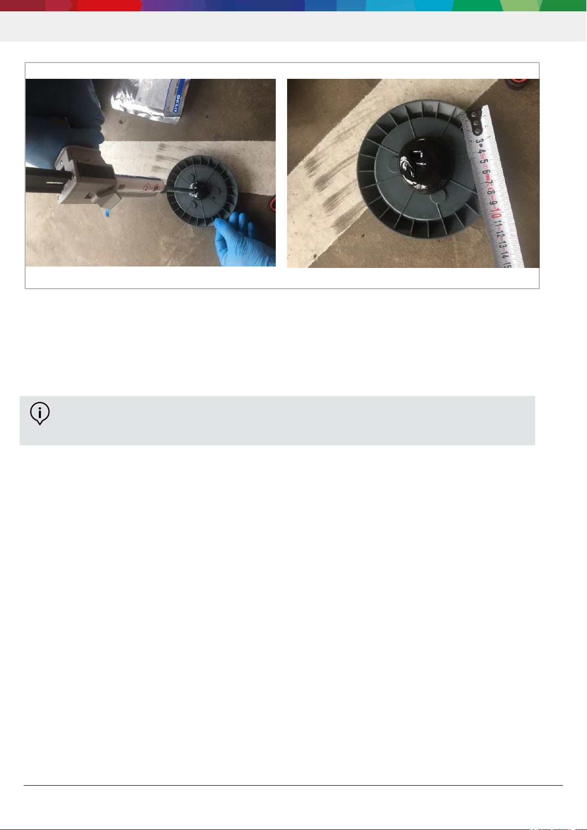
Öffnen Sie die Verpackung der Sensorbasis erst kurz vor der Aufbringung des Klebstoffes, um Verunreinigungen zu
vermeiden und einen maximalen Nutzen aus dem Plasma Reinigungsverfahren zu ziehen. Im Fall von
DELO®-PUR 9692 tragen Sie etwa 40ml des Klebstoffes mittig auf (siehe Abb. 10 Klebstoffaufbringung und Abb. 11
Klebstoffmenge); wenn Sie eine 50ml Kartusche verwenden, können Sie diese komplett entleeren. Bringen Sie den
Klebstoff in der Form einer Blase zentral auf die Sensorbasis auf (Keine Schnecken oder gleichmäßige Fläche).
INFO:
Die Verwendung des Mischrohres ist wichtig für die Vermischung der 2 Komponenten des Klebstoffes
und für die resultierende Klebewirkung.
Parking Lot Sensor | PLS
7 | 14
Abbildung 10 Klebstoffaufbringung Abbildung 11 Klebstoffmenge
Bitte beachten Sie, dass der Klebstoff innerhalb weniger Minuten aushärtet, sobald die zwei Komponenten vermischt
werden.
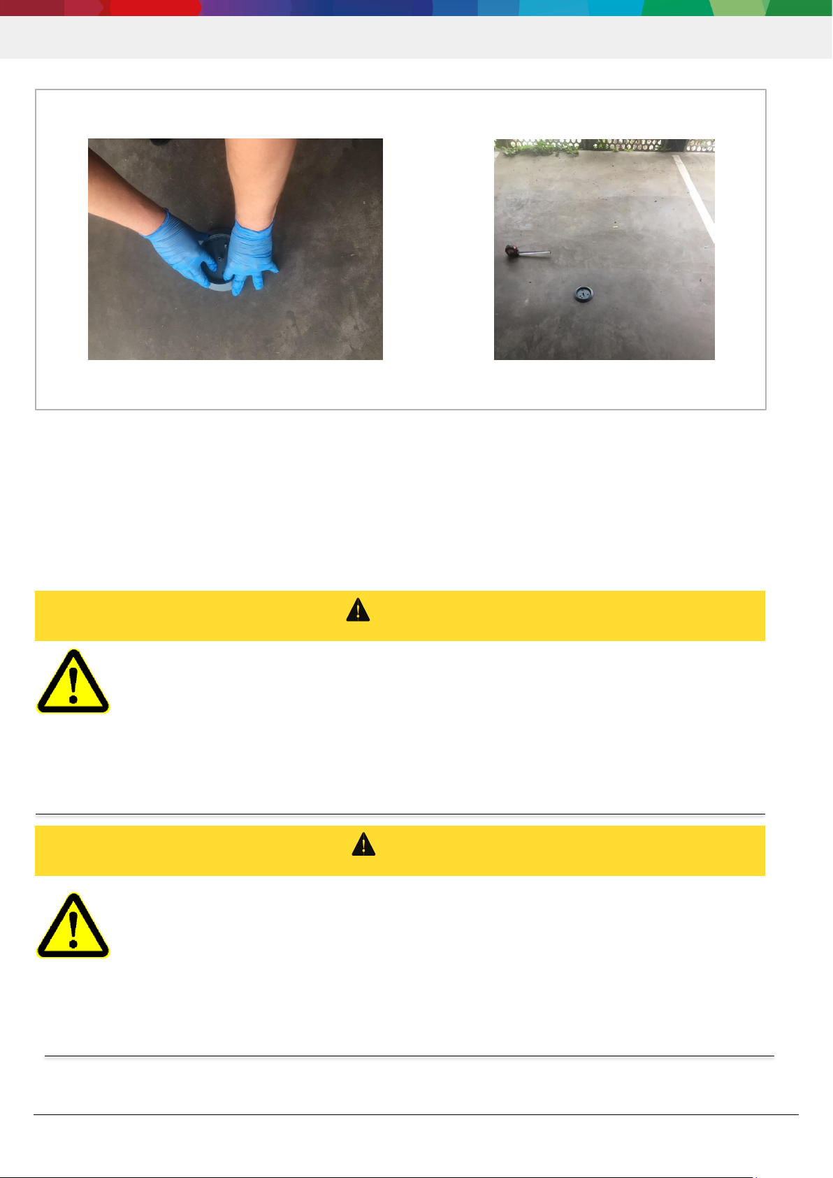
Nun können Sie den Sensor auf der Parkplatzmitte montieren, indem Sie einen leichten Druck auf die Sensorbasis
ausüben (siehe Abb. 12 Sensorbasis Aufbringung). Achten Sie darauf, dass der Sensor mittig auf dem Parkplatz
aufgebracht ist und das Bosch Logo auf der Sensorbasis in Richtung der Zufahrtsstraße zeigt (siehe Abb. 13
Sensorbasis installiert). Ein nachträgliches Verdrehen der Sensorbasis ist nicht möglich.
INFO:
Sobald der Klebstoff im Mischrohr ausgehärtet ist, kann dieses nicht weiterverwendet werden.
Typische Verarbeitungszeit des Klebstoffes bei Raumtemperatur sind etwa 5 min.
Parking Lot Sensor | PLS
8 | 14
Abbildung 12 Sensorbasis Aufbringung Abbildung 13 Sensorbasis installiert
Geben Sie dem Zweikomponentenklebstoff > 12h Zeit, um auszuhärten (handfest bei Raumtemperatur nach 30 min),
bevor Sie mit dem Einschrauben des Sensors beginnen. Lassen Sie den Parkplatz bis zur Montage des Sensors
abgesperrt, um Schäden (z.B. ein Abbrechen des Domes) an der Sensorbasis zu vermeiden.
2.3 Montage des Sensors
Warnung
Durch defekte Dichtungen kann Wasser in den Sensor eindringen und ihn beschädigen. Die
Funktionalität des Parking Lot Sensors ist bei falscher Montage nicht sichergestellt.
⇒ Achten Sie auf den korrekten Sitz der Dichtungsringe an Kappe und Sensor!
⇒ Installieren Sie die Sensoren nicht bei Regen.
⇒ Verwenden Sie keine beschädigten Komponenten!
⇒ Öffnen Sie das Sensorgehäuse nicht!
⇒ Verwenden Sie nur Originalersatzteile!
Warnung
Explosionsgefahr
Extreme Hitze kann zur Beschädigung der Batterie und des Sensors führen
.
⇒ Setzen Sie den Sensor keinen Temperaturen >85 °C aus!
⇒ Setzen Sie den Sensor nicht offenem Feuer aus!
Halten Sie bei Verwendung eines Gasbrenners (z.B. bei der Entfernung von Unkraut) einen Abstand von
mindestens 1,50 m zwischen der Flamme und dem Sensor ein!
Parking Lot Sensor | PLS
9 | 14
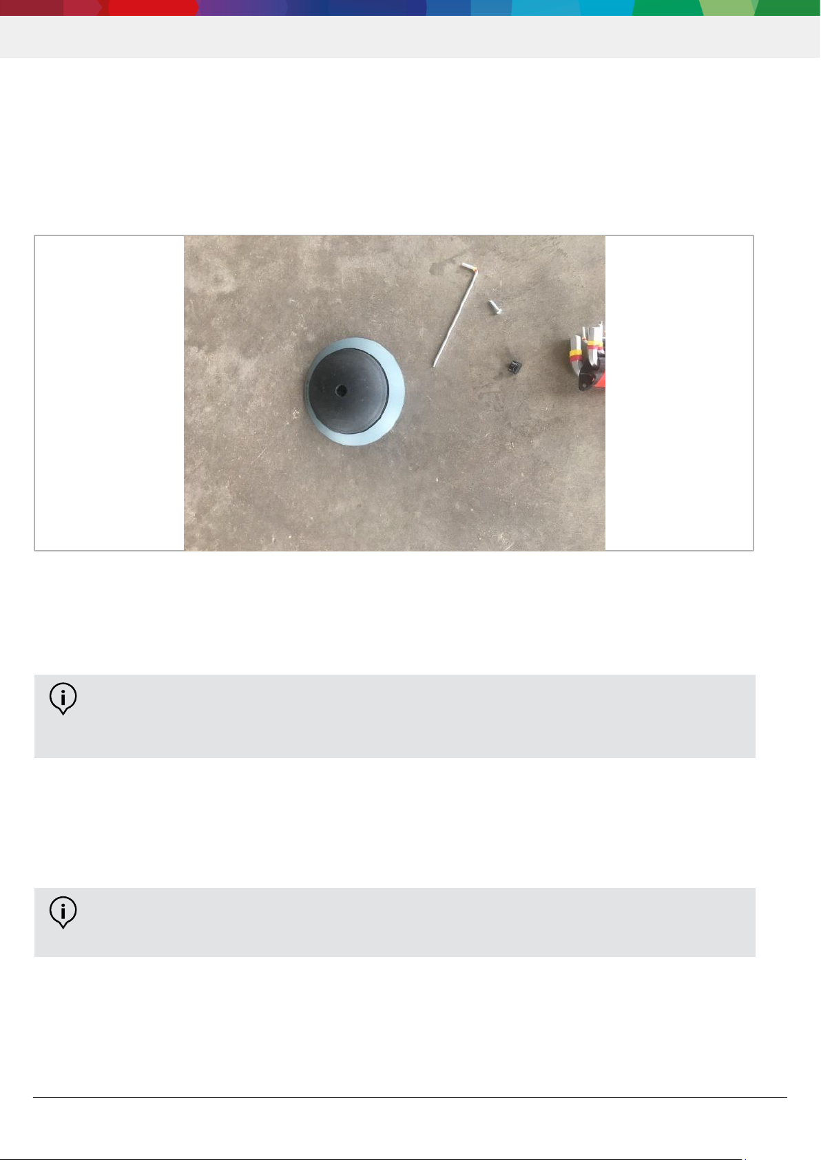
Der Sensor kann nach Aushärten des Klebstoffes in die Basis eingeschraubt werden. Zur Vereinfachung des
Einsetzens zeigt der Pfeil an der Unterseite des Sensors in Richtung des Bosch Ankers (siehe Abb. 14 Einsetzen /
Verschrauben des Sensors). Nach Einsetzen des Sensors vergehen ca. 2 Minuten, bis die ersten Messungen
durchgeführt werden. In dieser Zeit sollte das Einschrauben abgeschlossen sein, um ein optimales Einlernen des
Sensors zu gewährleisten. Zum Festschrauben verwenden Sie die T20 Schraube, und einen T20 Schraubendreher,
und wenden Sie ein Drehmoment zwischen 1,4 Nm und 1,8 Nm an. Verschließen Sie dann die Öffnung anschließend
mit der Sensor Verschlusskappe.
Abbildung 14 Einsetzen/ Verschrauben des Sensors
Nach abgeschlossener Montage des Sensors lernt der Sensor über Parkwechsel, was in seiner Umgebung passiert.
Nach ca. 10 Parkwechseln befindet sich der Sensor in seinem eingelernten Zustand.
2.4 Austausch / Entfernen des BOSCH Parking Lot Sensors
Zum Austausch des Sensors muss nur der Sensor erneuert werden. Hierfür entfernen Sie die Sensor
Verschlusskappe und lösen die T20 Schraube, anschließend kann der Sensor aus der Sensorbasis entfernt werden.
Um die Sensorbasis komplett von dem Parkplatz zu entfernen ist es notwendig mit einem Hammer und Meißel die
Klebewirkung zu zerstören, indem man parallel zur Parkplatzoberfläche die Sensorbasis abmeißelt. So entstehen auf
dem Parkplatz keine bleibenden Schäden.
INFO:
Während des Betriebs findet eine kontinuierliche automatische Kalibration des Parking Lot Sensors durch
Ein- und Ausparkevents statt.
INFO:
Ein Batteriewechsel ist nicht vorgesehen, stattdessen muss der Sensor ausgetauscht werden.

Parking Lot Sensor | PLS
10 | 14
2.5 Anlegen und Betreiben des Parking Lot Sensors im Back-End
Um den Sensor im LoRa Back-End anzulegen werden folgende Informationen benötigt, welche Ihnen von BCDS
GmbH bereitgestellt werden:
devEUI (Bsp. FCD6BD0000190001)
appKey (Bsp. AABBCCDDEEFFGGHHIIJJKKLLMMNNOOPP)
appEUI (FCD6BD0000190000)
Weitere Informationen zum Betreiben des Parking Lot Sensors finden Sie auf unserer Webseite: https://www.bosch-
connectivity.com/parking-lot-sensor/downloads/.

Parking Lot Sensor | PLS
11 | 14
3 Technische Daten
Tabelle 1 Gerätespezifikation - Parking Lot Sensor PLS mit TPS110 EU Sensorkern
Weitere Informationen können dem Datenblatt auf der Webseite: https://www.bosch-connectivity.com/parking-lot-
sensor/downloads/ entnommen werden.
EIGENSCHAFTEN
WERTE
Temperaturbereich
-30 °C bis 65 °C
Luftfeuchtigkeit
0 – 97 %
Schutzklasse
IP67 / IPx9K
Abmessungen
⌀: 145,4 mm
H: 30,5 mm
Batterielebensdauer
Bis zu 5 Jahren
LoRa Frequenzen
863-865 / 868-868.6 / 869,4-869,65 MHz
Sendeleistung max. 14 dBm ERP
Radarfrequenz
2,4 – 2,4835 GHz
Sendeleistung max. -28 dBm EIRP
Masse
191 g
Parking Lot Sensor | PLS
12 | 14
4 Rechtliche Informationen
4.1 Entsorgungshinweis gemäß ElektroG und WEEE Richtlinie 2012/19/EU
Der Sensor sowie sämtliche Einzelteile dürfen nicht im Hausmüll oder Industriemüll entsorgt
werden. Sie sind verpflichtet, die Entsorgung des Gerätes nach Ende der Lebensdauer nach den
Anforderungen des ElektroG durchzuführen, um die Umwelt zu schützen und Abfallmengen durch
Wiederverwertung zu reduzieren. Für nähere Informationen und Durchführung der Entsorgung
wenden Sie sich bitte an dazu zertifizierte Entsorgungsdienstleister.
Die Sensoren enthalten eine Li Batterie, die getrennt zu entsorgen ist.
4.2 EU-Konformitätserklärung
Hersteller: Bosch Connected Devices and Solutions GmbH
Ludwig-Erhard-Straße 2
72760 Reutlingen
Germany
Produkttyp: Parking Lot Sensor
Bezeichnung: TPS110 EU
Hiermit erklärt die Bosch Connected Devices and Solutions GmbH, dass der Funkanlagentyp „Parking Lot Sensor
TPS110 EU“ der Richtlinie 2014/53/EU (Radio Equipment Directive) und der Richtlinie 2011/65/EU (RoHS Directive)
entspricht.
Der vollständige Text der EU-Konformitätserklärung ist unter der folgenden Internetadresse verfügbar:
https://www.bosch-connectivity.com/parking-lot-sensor/downloads/.
4.3 Hinweis für den Transport
Der TPS110 EU enthält eine Lithium Metall Batterie und ist als UN 3091 (Lithium-Metall-Batterien in Ausrüstungen
verpackt, einschließlich Batterien aus Lithiumlegierungen) klassifiziert.
Die Lithium Metall Batterie des TPS110 EU erfüllt die Anforderungen des UN Manual of Tests and Criteria, Part III,
Subsection 38.3. Die Batterie enthält weniger als 2g Lithium.
Packstücke mit bis zu 2 TPS110 EU und maximal 2 Packstücken pro Sendung sollten nicht von besonderen
Regelungen zum Transport betroffen sein. Klären Sie dies zur Sicherheit jedoch mit Ihrem Transportdienstleister ab
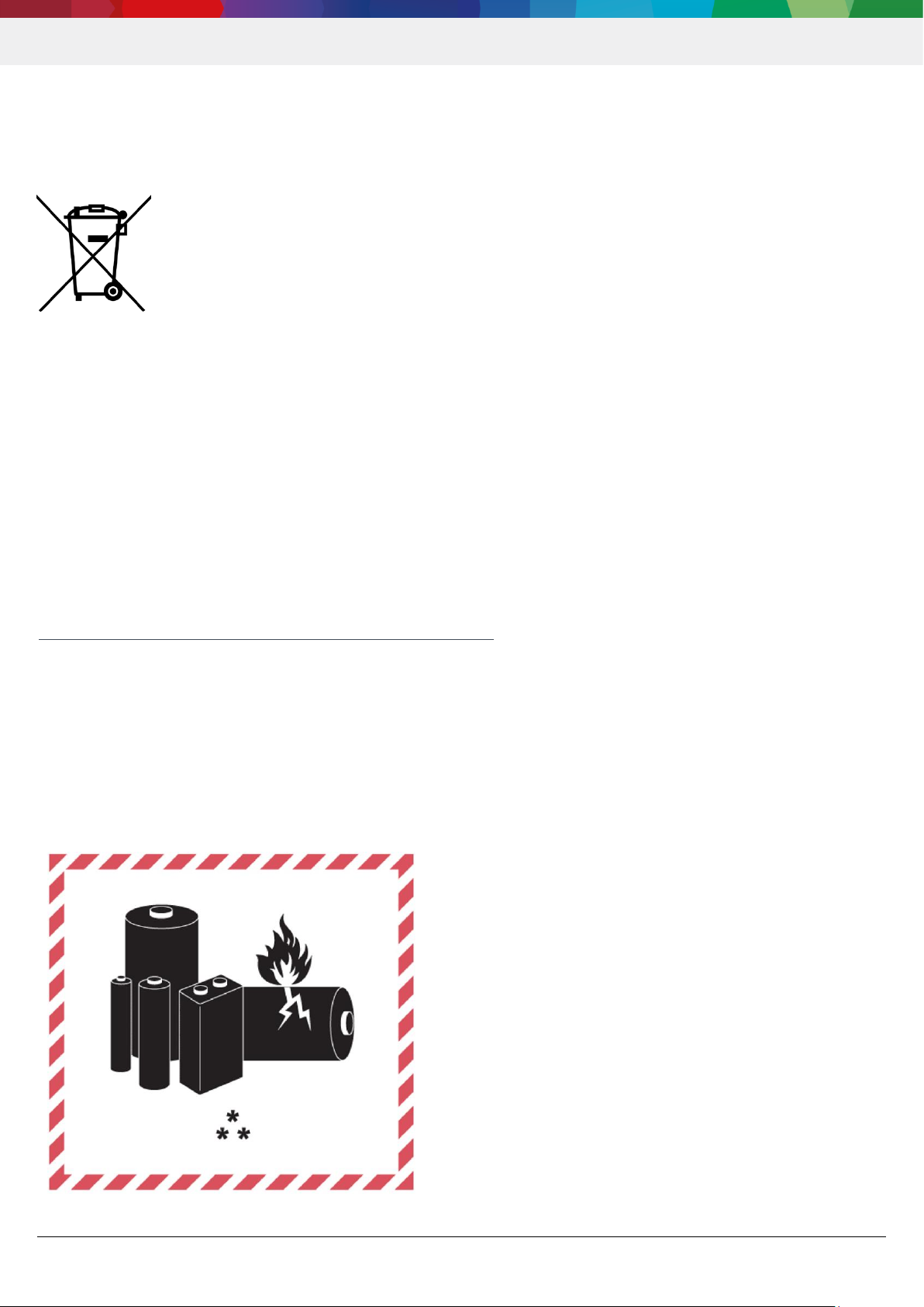
Packstücke mit mehr als 2 TPS110 EU (beispielsweise auch für Rücksendungen an BCDS) müssen das im Anhang
angegebene Lithium Metall Batterien Abfertigungskennzeichen tragen.
UN 3091
** Tel. +49 7121 35-36941

Parking Lot Sensor | PLS
13 | 14
Die folgenden Voraussetzungen sind zu erfüllen:
Die Lithium Metall Batterien sind im TPS110 EU enthalten.
Der TPS110 EU und die enthaltenen Batterien sind nicht beschädigt.
Der TPS110 EU enthält die original mitgelieferten Lithium Metall Batterien. Ein Ersatz verbrauchter Batterien ist
nicht erlaubt.
Der TPS110 EU ist durch eine robuste Verpackung geschützt.
Es dürfen der Verpackung keine weiteren separaten Batterien beigefügt werden.
Frachtpapiere müssen einen Hinweis enthalten, dass die Sendung “Lithium Metall Batterien in Konformität mit
Sektion II der Verpackungsvorschrift PI 970” für Luftfracht bzw. „Freigestellte Lithium Batterien nach
Sondervorschrift 188“ für Straßentransport enthält.
Verpackungen mit dem TPS110 EU in Übereinstimmung mit den zuvor genannten Vorschriften dürfen in einer
Umverpackung konsolidiert eingebunden werden, die das Lithium Batterie Etikett und als
„Umverpackung“ gekennzeichnet ist.
Beachten Sie, dass dieses Dokument keine vollständige und aktuelle Information aller zu beachtenden Anforderungen
enthalten kann. Der Versender ist für die Erfüllung aller Anforderungen für den Transport von Lithium Batterien selber
verantwortlich. Die IATA (International Air Transportation Association gibt weitere Vorschriften zum Transport von
Lithium Batterien heraus IATA (International Air Transport Association) Lithium Battery Guidance Document, die für
den Lufttransport zu beachten sind. Die IATA- Vorschriften für den Transport per Luftfracht sind am restriktivsten und
geben dadurch ebenfalls Hilfestellung beim Straßen- und Seetransport.
Der Kunde bzw. der Versender sollte sich jedoch nach nationalen Anforderungen erkundigen sowie nach eventuellen
Anforderungen von seinem Transportdienstleister.
4.4 OSS Hinweis
Die Firmware des Parking Lot Sensors enthält free open source software („FOSS“) Komponenten, die bestimmten FOSS
Lizenzbedingungen unterworfen sind. Der Kunde hat die sich daraus ergebenden Verpflichtungen zu beachten. Die
detaillierten FOSS Lizenzbedingungen sind unter der folgenden Internetadresse verfügbar https://www.bosch-
connectivity.com/parking-lot-sensor/downloads/

Parking Lot Sensor | PLS
14 | 14
Bosch Connected Devices and Solutions GmbH
BCDS
Ludwig-Erhard-Straße 2
72760 Reutlingen
Germany
support@bosch-connectivity.com

Parking Lot Sensor | PLS
1 | 14
Parking Lot Sensor | PLS
User manual 1.0.2

Parking Lot Sensor | PLS
2 | 14
Table of contents
1 General description and intended use 3
2 Assembly and commissioning 3
2.1 Installation requirements ..................................................................................................................................... 3
2.2 Installing the sensor base ................................................................................................................................... 4
Required material for installing the parking lot sensor ................................................................................................ 4
Preparation of the parking space ................................................................................................................................ 4
Installation of the sensor base .................................................................................................................................... 6
2.3 Installing the sensor ............................................................................................................................................ 8
2.4 Replacing/removing the BOSCH Parking Lot Sensor ......................................................................................... 9
2.5 Setup and operation of the parking lot sensor in the backend .......................................................................... 10
3 Technical specifications 11
4 Legal information 12
4.1 Disposal note in accordance with ElektroG and WEEE Directive 2012/19/EU ................................................ 12
4.2 EU Declaration of Conformity............................................................................................................................ 12
4.3 Note for transport .............................................................................................................................................. 12
4.4 OSS note ........................................................................................................................................................... 13
Parking Lot Sensor | PLS
3 | 14
1 General description and intended use
The Parking Lot Sensor PLS with TPS110 EU sensor core is designed for detecting parked vehicles in parking lots.
The Parking Lot Sensor PLS with TPS110 EU sensor core is not designed for use in life-sustaining applications,
safety-critical applications or applications for which a malfunction could lead to bodily harm, death or severe property
damage. Only use the Parking Lot Sensor with components approved by BCDS. This user manual is valid for the
Parking Lot Sensor PLS with TPS110 EU sensor core by BCDS.
2 Assembly and commissioning
2.1 Installation requirements
The Customer must comply with all applicable laws and regulations for the installation and operation of the Product,
and if necessary, obtain necessary approvals. The Customer must take appropriate measures to avoid injury of third
parties, for example, by them tripping over the Product. Therefore, the product should, for instance, not be installed on
the sidewalk.
Before installing the sensors, make sure that the necessary infrastructure is working properly - make sure the
gateways are switched on, that a stable Internet connection has been established, and that there is a backend
connection. The backend, as well as the associated management software, must be functional. Make sure that all of
the required components (see Fig. 1 Parking Lot Sensor PLS with TPS110 EU sensor core), as well as the tools, are
ready.
Figure 1 Parking Lot Sensor PLS with TPS110 EU sensor core
1 Cap
2 Screw
4 Base (sensor base)
3 Core (sensor TPS110 EU)
Parking Lot Sensor | PLS
4 | 14
2.2 Installing the sensor base
The sensor base is attached to the substrate (e.g., concrete, asphalt). To do this, we recommend a two-component
adhesive. We have already had good experience with the following adhesive: DELO®-PUR 9692 (universal 2component polyurethane adhesive available in 50 ml and 200 ml cartridges). We will be happy to support you with
procurement. We recommend attaching several sensor bases first and only then installing the sensors.
Required material for installing the parking lot sensor
Figure 2 Material for attachment
1 Disposable gloves (protection against contact with adhesive)
2 Two-component adhesive
3 Adhesive press (these differ, depending on the cartridge size)
4 Mixing tip
5 Tape rule
6 Sensor base
7 Sensor core (sensor)
8 T20 screw
9 Sensor cap (sensor sealing cap)
Preparation of the parking space
The parking space must be free of dirt, dust, oil, water and other contaminants. For this purpose, at least one swept
area should be prepared. However, it is recommended to clean the surface to remove contamination using a highpressure cleaner and a burner. The installation must take place in the center of the parking space (intersection of the
two diagonals, see Fig. 3) in order to ensure optimum sensor accuracy.
Figure 3 Determination of the center of the parking space
Parking Lot Sensor | PLS
5 | 14
Figure 4 Available parking space for sensor installation
To provide the adhesive with a closed substrate, the surface intended for the installation of the sensor base should be
free of any gaps or misalignment (see Figure 4 Available parking space for sensor installation). This is crucial for the
contact surface and the adhesive effect of the sensor.
Figure 5 Substrate example (continuous) Figure 6 Substrate example (gap)
INFORMATION:
For the bonding procedure, please follow the instructions of the adhesive manufacturer (e.g.,
temperature, safety information and work instructions).
A parking space cleaning should be clarified in advance with the parking lot operator so that the
treatment does not result in removal of existing coatings.
Parking Lot Sensor | PLS
6 | 14
Installation of the sensor base
Insert the adhesive cartridge into the glue gun/adhesive press (Fig. 7 Inserting the adhesive cartridge; in the case of
DELO®-PUR 9692, the mixing ratio is 1:1, so you do not have to pay attention to the orientation of the cartridge). Then
attach the mixing tip on the cartridge by removing the cartridge cap (Fig. 8 Sealing cap adhesive cartridge) and
attaching the mixing tube (Fig. 9 Mixing tube on adhesive cartridge; here, bayonet fitting).
Figure 7 Inserting the cartridge Figure 8 Sealing cap Figure 9 Mixing tube
To avoid contamination and to get the maximum use out of the plasma cleaning process, open the sensor base
package just before applying the adhesive. In the case of DELO® PUR 9692, you apply about 40 ml of the adhesive in
the middle (see Fig. 10 Applying adhesive, and Fig. 11 Amount of adhesive); if you use a 50 ml cartridge, you can
empty it completely. Apply the adhesive in the form of a bubble in the center of the sensor base (no screws or even
surface).
INFORMATION:
The use of the mixing tube is important for mixing the two components of the adhesive and for the
resulting adhesive effect.
Parking Lot Sensor | PLS
7 | 14
Figure 10 Adhesive application Figure 11 Adhesive amount
Please note that, as soon as the two components are mixed, the adhesive cures within a few minutes.
Now you can mount the sensor in the center of the parking space by applying light pressure on the sensor base (see
Fig. 12 Sensor base attachment). Make sure that the sensor is centered in the parking space and that the Bosch logo
on the sensor base points towards the access road (see Figure 13 Sensor base installed). Subsequent twisting of the
sensor base is not possible.
INFORMATION:
Once the adhesive in the mixing tube has cured, it cannot be used again. At room temperature, a
typical processing time for the adhesive is about 5 minutes.

Parking Lot Sensor | PLS
8 | 14
Figure 12 Sensor base attachment Figure 13 Sensor base installed
Allow the two-component adhesive > 12 h to cure (hand-tight at room temperature after 30 min) before you screw in
the sensor. Keep the parking space closed off until the sensor is installed to prevent damage (such as breaking the
dome) to the sensor base.
2.3 Installing the sensor
Warning
Defective seals can cause water to get into the sensor and damage it. The functionality of the parking lot
sensor is not guaranteed if it is installed incorrectly.
⇒ Make sure that the sealing rings on the cap and sensor are seated correctly!
⇒ Do not install the sensors when it is raining.
⇒ Do not use damaged components!
⇒ Do not open the sensor housing!
⇒ Only use original replacement parts!
Warning
Risk of explosion
Extreme heat can damage the battery and the sensor.
⇒ Do not expose the sensor to temperatures above 85 °C!
⇒ Do not expose the sensor to open flames!
When using a gas burner (for example, when removing weeds), keep a distance of at least 1.50 m between
the flame and the sensor!
Parking Lot Sensor | PLS
9 | 14
The sensor can be screwed into the base after the adhesive has cured. To simplify insertion, the arrow on the bottom
of the sensor points towards the Bosch logo (see Figure 14 Installing/screwing in the sensor). After inserting the
sensor, it will take approx. 2 minutes until the first measurements are carried out. During this time, the sensor should
be completely screwed in to ensure optimum teaching of the sensor. To tighten it, use the T20 screw and a
T20 screwdriver and tightening torque with at least 1.4 Nm up to a maximum of 1.8 Nm. And then close the opening
with the sensor sealing cap.
Figure 14 Installing/screwing in the sensor
After the installation of the sensor, the sensor learns about parking changes, which happens in its vicinity. After
approx. 10 parking changes, the sensor is in its taught-in state.
2.4 Replacing/removing the BOSCH Parking Lot Sensor
To replace the parking lot sensor, only the sensor needs to be replaced. To do this, remove the sensor cap and loosen
the T20 screw; then remove the sensor from the sensor base.
To completely remove the sensor base from the parking space, it is necessary to use a hammer and chisel to destroy
the adhesive effect by chiseling the sensor base parallel to the parking space surface. As a result, there is no
permanent damage to the parking space.
INFORMATION:
During operation, a continuous automatic calibration of the parking lot sensor takes place through "parking"
and "exiting parking space'' events.
INFORMATION:
A battery replacement is not intended; instead, the sensor must be replaced.

Parking Lot Sensor | PLS
10 | 14
2.5 Setup and operation of the parking lot sensor in the backend
In order to set up the sensor in the LoRaWAN backend, the following information is required, which will be provided to
you by BCDS GmbH:
devEUI (for example, FCD6BD0000190001)
appKey (for example, AABBCCDDEEFFGGHHIIJJKKLLMMNNOOPP)
appEUI (FCD6BD0000190000)
Additional information on operating the parking lot sensor can be found on our website at https://www.bosch-
connectivity.com/parking-lot-sensor/downloads/.

Parking Lot Sensor | PLS
11 | 14
3 Technical specifications
Table 1 Device specifications - Parking Lot Sensor PLS with TPS110 EU sensor core
Additional information can be found in the datasheet on the website at https://www.bosch-connectivity.com/parking-lot-
sensor/downloads/.
PROPERTIES
VALUES
Temperature range
-30 °C to 65 °C
Humidity
0 – 97%
Protection class
IP67/IPx9K
Dimensions
⌀: 145.4 mm
H: 30.5 mm
Battery life
Up to 5 years
LoRa frequencies
863-865/868-868.6/869.4-869.65 MHz
Transmitting power max. 14 dBm ERP
Radar frequency
2.4–2.4835 GHz
Transmission power max. -28 dBm EIRP
Mass
191 g
Parking Lot Sensor | PLS
12 | 14
4 Legal information
4.1 Disposal note in accordance with ElektroG and WEEE Directive 2012/19/EU
The sensor, as well as all the individual parts, must not be disposed of with household waste or
industrial waste. You are obliged to dispose of the device at the end of its service life in accordance
with the requirements of ElektroG in order to protect the environment and to reduce waste through
recycling.
For additional information and how to carry out disposal, please contact the certified disposal
service providers.
The sensors contain a Li battery, which must be disposed of separately.
4.2 EU Declaration of Conformity
Manufacturer: Bosch Connected Devices and Solutions GmbH
Ludwig-Erhard-Straße 2
72760 Reutlingen
Germany
Product type: Parking lot sensor
Designation: TPS110 EU
Bosch Connected Devices and Solutions GmbH hereby declares that the "Parking Lot Sensor TPS110 EU" radio
system type is in compliance with Directive 2014/53/EU (Radio Equipment Directive) and Directive 2011/65/EU (RoHS
Directive).
The full text of the EU Declaration of Conformity is available at the following web address:
https://www.bosch-connectivity.com/parking-lot-sensor/downloads/.
4.3 Note for transport
The TPS110 EU contains a lithium metal battery and is classified as UN 3091 (lithium metal batteries packed in
equipment, including lithium alloy batteries).
The lithium metal battery for the TPS110 EU complies with the requirements of the UN Manual of Tests and Criteria,
Part III, Subsection 38.3. The battery contains less than 2 g of lithium. Packages with up to 2 TPS110 EU and a
maximum of 2 packages per shipment should not be affected by special transport regulations. For your safety,
however, check with your transport service provider. Packages with more than 2 TPS110 EU (for example, also for
returns to BCDS) must carry a lithium battery handling label specified in the appendix.
* UN 3091
** Telephone +49 7121 35-36941

Parking Lot Sensor | PLS
13 | 14
The following requirements must be met:
The lithium metal batteries are included in the TPS110 EU.
The TPS110 EU and the included batteries are not damaged.
The TPS110 EU contains the original supplied lithium metal batteries. Replacement of used batteries is not permitted.
The TPS110 EU is protected by sturdy packaging.
No additional separate batteries may be added to the packaging.
Shipping documents must include a note stating that the shipment contains "Lithium metal batteries in compliance with
Section II of Packing Instruction PI 970" for air freight, or "Exempted lithium batteries under Special Provision 188"
for road transport.
Packaging with the TPS110 EU, in accordance with the above-mentioned regulations, may be consolidated in outer
packaging that is marked with the lithium battery label and is designated as "outer packaging."
Note that this document cannot contain complete and up-to-date information on all the requirements to be observed.
The consignor is responsible for fulfilling all the requirements for the transport of lithium batteries themselves. The
International Air Transportation Association (IATA) has issued further regulations on the transport of lithium batteries
IATA (International Air Transport Association) Lithium Battery Guidance Document, which must be observed for air
transport. The IATA regulations for transport by air freight are the most restrictive and thus also provide assistance for
road and sea transport.
However, the customer or consignor should inquire about national requirements as well as any requirements from their
transport service provider.
4.4 OSS note
The parking lot sensor firmware includes free open source software ("FOSS") components subject to certain FOSS license
terms.
The customer must observe the resulting obligations. The detailed FOSS license terms are available at the following web
address: https://www.bosch-connectivity.com/parking-lot-sensor/downloads/

Parking Lot Sensor | PLS
14 | 14
Bosch Connected Devices and Solutions GmbH
BCDS
Ludwig-Erhard-Straße 2
72760 Reutlingen
Germany
support@bosch-connectivity.com

Parking Lot Sensor | PLS
1 | 14
Parking Lot Sensor | PLS
Manual de usuario 1.0.2

Parking Lot Sensor | PLS
2 | 14
Índice
1 Descripción general y uso previsto 3
2 Montaje y puesta en servicio 3
2.1 Requisitos de instalación .................................................................................................................................... 3
2.2 Montaje de la base del sensor ............................................................................................................................ 4
Material necesario para la instalación del Parking Lot Sensor ................................................................................... 4
Preparación de la plaza de aparcamiento .................................................................................................................. 4
Instalación de la base del sensor ................................................................................................................................ 6
2.3 Montaje del sensor .............................................................................................................................................. 8
2.4 Sustitución/retirada del BOSCH Parking Lot Sensor .......................................................................................... 9
2.5 Crear y operar el Parking Lot Sensor en el backend ........................................................................................ 10
3 Datos técnicos 11
4 Información legal 12
4.1 Instrucción de eliminación según la ley alemana sobre aparatos eléctricos y electrónicos (ElektroG) y la
Directiva RAEE 2012/19/UE ............................................................................................................................... 12
4.2 Declaración de conformidad UE ....................................................................................................................... 12
4.3 Indicación para el transporte ............................................................................................................................. 12
4.4 Indicación OSS ................................................................................................................................................. 13

Parking Lot Sensor | PLS
3 | 14
1 Descripción general y uso previsto
El Parking Lot Sensor PLS con el núcleo de sensor TPS110 EU está diseñado para detectar vehículos aparcados en
zonas de estacionamiento. No está diseñado para ser utilizado en aplicaciones médicas, aplicaciones de seguridad o
aplicaciones para las que el funcionamiento incorrecto podría provocar daños personales, la muerte o daños
materiales graves. Utilizar el sensor de estacionamiento solo con componentes que hayan sido aprobados por BCDS.
Este manual de usuario es solo válido para el sensor de estacionamiento PLS con núcleo de sensor TPS110 EU por
BCDS.
2 Montaje y puesta en servicio
2.1 Requisitos de instalación
El cliente debe cumplir con todas las leyes y normas vigentes referentes a la instalación y el funcionamiento del
producto, y en caso necesario, obtener las aprobaciones necesarias. El cliente debe tomar las medidas necesarias
para evitar dañar a terceras personas, debido por ejemplo, a tropiezos con el producto. Por lo tanto, el producto, no
debería instalarse por ejemplo, en aceras.
Antes de instalar los sensores, asegúrese de que la infraestructura necesaria funcione correctamente. Preste
atención a que las puertas de enlace estén activadas, tengan una conexión a internet estable y estén conectadas al
backend. Tanto el backend como el correspondiente software de gestión deben funcionar correctamente. Asegúrese
de que todos los componentes necesarios (la figura 1 sensor de estacionamiento PLS con núcleo de sensor TPS110
EU) y las herramientas estén listos.
Figura 1 Sensor de estacionamiento PLS con núcleo de sensor TPS110 EU
1 Cap
2 Tornillo
4 Base (base del sensor)
3 Core (sensor
TPS110 EU)

Parking Lot Sensor | PLS
4 | 14
2.2 Montaje de la base del sensor
La base del sensor se pega al suelo (p. ej. hormigón, asfalto). Para ello recomendamos un pegamento de dos
componentes.
Hemos tenido buena experiencia con el pegamento siguiente: DELO®-PUR 9692 (pegamento de poliuretano
universal de dos componentes disponible en cartuchos de 50 ml y 200 ml). Estamos encantados de poder ayudarle
con la compra. Recomendamos pegar primero varias bases de sensor y montar los sensores después.
Material necesario para la instalación del Parking Lot Sensor
Figura 2 Material para realizar el pegado
1 Guantes desechables (protección contra el contacto con el pegamento)
2 Pegamento de dos componentes
3 Prensa (esta varía en función del tamaño de cartucho)
4 Boquilla mezcladora
5 Cinta métrica
6 Sensor base (base del sensor)
7 Sensor core (sensor)
8 Tornillo T20
9 Sensor cap (tapa de sensor)
Preparación de la plaza de aparcamiento
La plaza de aparcamiento debe estar libre de suciedad, polvo, aceite, agua y otras impurezas. Para ello debe
prepararse una superficie que se haya limpiado con escoba. Sin embargo, se recomienda limpiar la superficie de
impurezas con un limpiador de alta presión y un quemador.
La instalación debe realizarse en el centro de la plaza de aparcamiento (intersección de ambas diagonales, ver la fig.
3) de la plaza de aparcamiento a fin de garantizar la óptima precisión de sensor.
Figura 3 Determinación del centro de la plaza de aparcamiento

Parking Lot Sensor | PLS
5 | 14
Figura 4 Plaza de aparcamiento libre para la instalación del sensor
La superficie prevista para la instalación de la base del sensor no debe presentar fisuras ni irregularidades para
proporcionar al adhesivo una superficie cerrada (ver la fig. 4 Plaza de aparcamiento libre para la instalación del
sensor). Esto es crucial para la superficie de contacto y el efecto adhesivo del sensor.
Figura 5 Ejemplo de suelo (sin irregularidades) Figura 6 Ejemplo de suelo (fisura)
INFORMACIÓN:
Para el pegado, siga las instrucciones del fabricante del pegamento (p. ej. temperatura, indicaciones de
seguridad e instrucciones de trabajo).
La limpieza de la plaza de aparcamiento debe acordarse con el dueño de tal modo que el tratamiento no
implique ningún desprendimiento de las capas existentes.

Parking Lot Sensor | PLS
6 | 14
Instalación de la base del sensor
Inserte el cartucho de pegamento en la pistola o prensa (fig. 7 Introducción del cartucho de pegamento; en caso del
pegamento DELO®-PUR 9692, la relación de mezcla es de 1:1 por lo que no es necesario prestar atención a la
orientación del cartucho). Monte a continuación la boquilla mezcladora en el cartucho retirando el cierre (fig. 8 Tapa
del cartucho de pegamento) y montando el tubo mezclador (fig. 9 Tubo mezclador en el cartucho de pegamento; aquí
cierre de bayoneta).
Figura 7 Introducción del cartucho Figura 8 Tapa Figura 9 Tubo mezclador
No abra el embalaje de la base del sensor hasta poco antes de la aplicación del pegamento para evitar impurezas y
aprovechar al máximo el método de limpieza por plasma. En caso de DELO® PUR 9692 deben aplicarse unos 40 ml
del pegamento en el centro (ver la fig. 10, Aplicación de pegamento y fig. 11, Cantidad de pegamento). Si utiliza un
cartucho de 50 ml, puede vaciarlo por completo. Aplique el pegamento en forma de una burbuja en el centro de la
base del sensor (no dibuje caracoles ni una superficie uniforme).
INFORMACIÓN:
La utilización del tubo mezclador es importante para la mezcla de los 2 componentes del pegamento y
el efecto adhesivo resultante.

Parking Lot Sensor | PLS
7 | 14
Figura 10 Aplicación de pegamento Figura 11 Cantidad de pegamento
Tenga en cuenta que, en cuanto se mezclen los dos componentes, el pegamento se endurece en pocos minutos.
Ahora puede montar el sensor en el centro de la plaza de aparcamiento ejerciendo una ligera impresión sobre la base
del sensor (ver la fig. 12 Aplicación de la base del sensor). Preste atención a que el sensor esté centrado en la plaza
de aparcamiento y que el logotipo de Bosch en la base del sensor esté orientado hacia la vía de acceso (ver la fig. 13
Base del sensor instalada). Posteriormente no es posible girar la base del sensor.
INFORMACIÓN:
Una vez que se haya endurecido el pegamento en el tubo mezclador, no se puede seguir utilizando. El
tiempo de uso típico del pegamento a temperatura ambiente es de unos 5 minutos.

Parking Lot Sensor | PLS
8 | 14
Figura 12 Aplicación de la base del sensor Figura 13 Base del sensor instalada
El pegamento de dos componentes necesita > 12 horas para endurecerse (apriete a mano a temperatura ambiente
después de
30 minutos) antes de enroscar el sensor. La plaza de aparcamiento debe estar cerrada hasta el montaje del sensor a
fin de evitar que se produzcan daños (p. ej. rotura del mandril) en la base del sensor.
2.3 Montaje del sensor
Advertencia
Si las juntas están defectuosas, puede entrar agua en el sensor y provocar daños. La funcionalidad del
Parking Lot Sensor no queda garantizada si el montaje no se ha realizado correctamente.
⇒ ¡Preste atención al asiento correcto de los anillos de junta en la tapa y en el sensor!
⇒ No instale los sensores cuando llueve.
⇒ ¡No utilice componentes dañados!
⇒ ¡No abra la caja del sensor!
⇒ ¡Utilice solo recambios originales!
Advertencia
Peligro de explosión
Un calor extremo puede provocar daños en la pila y el sensor.
⇒ ¡No exponga el sensor a temperaturas >85 °C!
⇒ ¡No exponga el sensor a fuego desprotegido!
¡En caso de utilizar un quemador de gas (p. ej. para eliminar las malas hierbas), debe mantener una
distancia de al menos 1,50 m entre la llama y el sensor!

Parking Lot Sensor | PLS
9 | 14
Se puede enroscar el sensor en la base después de que se haya endurecido el pegamento. Para simplificar la
inserción, la flecha en la parte inferior del sensor apunta hacia el símbolo del ancla de Bosch (ver la fig. 14
Insertar/atornillar el sensor). Después de insertar el sensor transcurren aproximadamente 2 minutos antes de que se
realicen las primeras mediciones. Durante este tiempo, se debe completar el enroscado para garantizar la óptima
programación del sensor. Para apretarlo, utilizar un tornillo T20 y un destornillador T20 y un par de apriete con al
menos 1,4 Nm hasta un máximo de 1,8 Nm. Después cerrar la abertura con la tapa hermética del sensor.
Figura 14 Insertar/atornillar el sensor
Después de la instalación del sensor, este se va programando en base a los cambios que se realizan en la plaza de
aparcamiento para así conocer lo que sucede en su entorno. Después de aproximadamente 10 cambios, el sensor
está programado.
2.4 Sustitución/retirada del BOSCH Parking Lot Sensor
Para reemplazar el sensor, solo se necesita reemplazar el sensor mismo. Para ello debe retirar la tapa del sensor y
soltar el tornillo T20, a continuación, retire el sensor de la base del sensor.
Para retirar completamente la base del sensor de la plaza de aparcamiento, es necesario usar un martillo y un cincel
para destruir el efecto adhesivo al cincelar la base del sensor paralela a la superficie de la plaza de aparcamiento. Por
lo tanto, no se producen daños permanentes en la plaza de aparcamiento.
INFORMACIÓN:
Durante el servicio, se realiza una calibración automática continua del Parking Lot Sensor metiendo y
sacando los coches.
INFORMACIÓN:
No está previsto un cambio de pila, en su lugar se debe cambiar el sensor.

Parking Lot Sensor | PLS
10 | 14
2.5 Crear y operar el Parking Lot Sensor en el backend
Para crear el sensor en el backend LoRa, se requiere la siguiente información que será facilitada por BCDS GmbH:
devEUI (ejemplo: FCD6BD0000190001)
appKey (ejemplo AABBCCDDEEFFGGHHIIJJKKLLMMNNOOPP)
appEUI (FCD6BD0000190000)
Encontrará información adicional sobre el funcionamiento del Parking Lot Sensor en nuestra página web:
https://www.bosch-connectivity.com/parking-lot-sensor/downloads/.

Parking Lot Sensor | PLS
11 | 14
3 Datos técnicos
Tabla 1 Especificación del dispositivo - Sensor de estacionamiento PLS con núcleo de sensor TPS110 EU
Encontrará información adicional en la ficha de datos en nuestra página web: https://www.bosch-
connectivity.com/parking-lot-sensor/downloads/ .
CARACTERÍSTICAS
VALORES
Rango de temperatura
-30 °C a 65 °C
Humedad del aire
0 – 97 %
Clase de protección
IP67 / IPx9K
Dimensiones
⌀: 145,4 mm
Altura: 30,5 mm
Vida útil de la pila
Hasta 5 años
Frecuencias LoRa
863-865 / 868-868.6 / 869,4-869,65 MHz
Potencia de transmisión máx. 14 dBm ERP
Frecuencia de radar
2,4 – 2,4835 GHz
Potencia de transmisión máx. -28 dBm EIRP
Masa
191 g

Parking Lot Sensor | PLS
12 | 14
4 Información legal
4.1 Instrucción de eliminación según la ley alemana sobre aparatos eléctricos y electrónicos
(ElektroG) y la Directiva RAEE 2012/19/UE
El sensor, así como todos los componentes, no deben desecharse con la basura doméstica o
industrial. Usted está obligado a desechar el dispositivo al final de su vida útil de acuerdo con los
requisitos de la ley alemana sobre aparatos eléctricos electrónicos (ElektroG) para proteger el
medio ambiente y reducir el volumen de residuos mediante reciclaje. Para información adicional y
la realización de la eliminación, rogamos que se ponga en contacto con una empresa de gestión de
residuos.
Los sensores contienen una pila de litio que debe desecharse por separado.
4.2 Declaración de conformidad UE
Fabricante: Bosch Connected Devices and Solutions GmbH
Ludwig-Erhard-Straße 2
72760 Reutlingen
Alemania
Tipo de producto: Parking Lot Sensor
Designación: TPS110 EU
Mediante la presente, Bosch Connected Devices and Solutions GmbH declara que el tipo de equipo radioeléctrico
"Parking Lot Sensor TPS110 EU" cumple la directiva 2014/53/UE (Radio Equipment Directive) y la directiva
2011/65/UE (RoHS Directive).
El texto completo de la Declaración de conformidad UE está disponible en la siguiente dirección web:
https://www.bosch-connectivity.com/parking-lot-sensor/downloads/.
4.3 Indicación para el transporte
El TPS110 EU incluye una pila de metal de litio y está clasificado según UN 3091 (pilas de metal de litio embaladas en
equipamientos, incluyendo pilas de aleaciones de litio).
La pila de metal de litio des TPS110 EU cumple los requerimientos de UN Manual of Tests and Criteria, Part III,
Subsection 38.3. La pila incluye menos de 2 g de litio.
Envases con hasta 2 TPS110 EU y un máximo de 2 envases por envío no deben verse afectados por las regulaciones
especiales de transporte. Sin embargo, para su seguridad, aclárelo con su proveedor de servicios de transporte.
Envases con más de 2 TPS110 EU (por ejemplo, también para devoluciones a BCDS) deben llevar la identificación de
despacho para pilas de metal de litio especificado en el anexo.
UN 3091
** Tel. +49 7121 35-36941

Parking Lot Sensor | PLS
13 | 14
Se deben cumplir los siguientes requisitos:
Las pilas de metal de litio están incluidas en el TPS110 EU.
El TPS110 EU y las pilas incluidas no han sufrido daños.
El TPS110 EU incluye las pilas de metal de litio originales suministradas. No se permite sustituir las pilas gastadas.
El TPS110 EU está protegido con un embalaje resistente.
No se deben añadir otras pilas adicionales al embalaje.
Los documentos de transporte deben incluir una nota que indique que el envío contiene "Pilas de metal de litio en
conformidad con la sección II de la prescripción de embalaje PI 970" para flete aéreo o "Pilas de litio autorizadas
según la prescripción especial 188" para el transporte por carretera.
Embalajes con el TPS110 UE conformes a las prescripciones anteriores pueden integrarse de forma consolidada
en un embalaje exterior que lleve una etiqueta con indicación sobre la pila de litio y que esté identificado como
"Embalaje exterior".
Tenga en cuenta que este documento no puede contener información completa y actualizada de todos los requisitos
que deben tener en cuenta. El expedidor es responsable de cumplir con todos los requisitos para el transporte de las
baterías de litio. La IATA (International Air Transportation Association) publica otras prescripciones sobre el transporte
de pilas de litio IATA (International Air Transport Association) Lithium Battery Guidance Document que se deben tener
en cuenta para el transporte aéreo. Las prescripciones de la IATA para el transporte mediante flete aéreo son las más
restrictivas por lo que pueden ser de ayuda también para el transporte marítimo y por carretera.
Sin embargo, el cliente o expedidor debe consultar los requisitos nacionales y los requisitos de su proveedor de
servicios de transporte.
4.4 Indicación OSS
El firmware del Parking Lot Sensor incluye componentes de software "free open source" ("FOSS") que están sujetos de
determinadas condiciones de licencia FOSS. El cliente debe observar las obligaciones resultantes. Las condiciones de
licencia FOSS en detalle están disponibles en la siguiente dirección web https://www.bosch-connectivity.com/parking-lot-
sensor/downloads/

Parking Lot Sensor | PLS
14 | 14
Bosch Connected Devices and Solutions GmbH
BCDS
Ludwig-Erhard-Straße 2
72760 Reutlingen
Alemania
support@bosch-connectivity.com

Parking Lot Sensor | PLS
1 | 14
Parking Lot Sensor | PLS
Manuale utente 1.0.2

Parking Lot Sensor | PLS
2 | 14
Indice
1 Descrizione generale e uso previsto 3
2 Montaggio e messa in funzione 3
2.1 Presupposti per l'installazione ............................................................................................................................. 3
2.2 Montaggio della base sensore ............................................................................................................................ 4
Materiale richiesto per l'installazione del Parking Lot Sensor ..................................................................................... 4
Preparazione del posto di parcheggio ........................................................................................................................ 4
Installazione della base sensore ................................................................................................................................. 6
2.3 Montaggio del sensore ........................................................................................................................................ 8
2.4 Sostituzione / Rimozione del Parking Lot Sensor BOSCH ................................................................................. 9
2.5 Installazione ed esercizio del Parking Lot Sensor nel back-end....................................................................... 10
3 Dati tecnici 11
4 Informazioni legali 12
4.1 Istruzioni per lo smaltimento secondo la direttiva ElektroG e WEEE 2012/19/UE ........................................... 12
4.2 Dichiarazione di conformità UE ......................................................................................................................... 12
4.3 Indicazioni per il trasporto ................................................................................................................................. 12
4.4 Indicazione OSS ............................................................................................................................................... 13

Parking Lot Sensor | PLS
3 | 14
1 Descrizione generale e uso previsto
Il Parking Lot Sensor PLS con nucleo del sensore TPS110 EU è stato progettato per rilevare la presenza di veicoli
parcheggiati nelle aree di stazionamento. Non è idoneo all'uso in situazioni di emergenza, cruciali, pericolose o in
situazioni in cui un guasto del dispositivo potrebbe causare lesioni a persone, decesso o gravi danni materiali.
Utilizzare il sensore di parcheggio solo con componenti approvati da BCDS. Il presente manuale d'uso è valido per il
sensore di parcheggio PLS con nucleo del sensore TPS110 EU prodotto da BCDS.
2 Montaggio e messa in funzione
2.1 Presupposti per l'installazione
Il Cliente deve attenersi a tutte le leggi e le normative applicabili per l'installazione e l'utilizzo del Prodotto e, se
necessario, ottenere le autorizzazioni indispensabili. Il Cliente deve adottare misure adeguate al fine di evitare lesioni
di parti terze, per esempio, evitare che queste inciampino sul Prodotto. Pertanto, il prodotto non deve essere installato,
ad esempio, sul marciapiede.
Prima di installare i sensori, accertare che l'infrastruttura necessaria funzioni correttamente; accertare che le gateway
siano inserite, che sia presente un collegamento Internet stabile e che questo sia collegato con il back -end. Il backend e il relativo software di gestione devono essere funzionali. Accertare inoltre che siano pronti tutti i componenti
richiesti (vedere figura 1 Sensore di parcheggio PLS con nucleo del sensore TPS110 EU) e gli attrezzi.
Figura 1 Sensore di parcheggio PLS con nucleo del sensore TPS110 EU
1 Cap
2 Vite
4 Base (base sensore)
3 Core (sensore
TPS110 EU)

Parking Lot Sensor | PLS
4 | 14
2.2 Montaggio della base sensore
La base sensore viene incollata al pavimento (per es. calcestruzzo, asfalto). A tale scopo si consiglia una colla
bicomponente.
Con la seguente colla abbiamo avuto già buone esperienze: DELO® PUR 9692 (colla poliuretanica bicomponente
universale disponibile in cartucce da 50 ml e 200 ml). Saremo lieti di consigliarla nell'acquisto. Si consiglia di incollare
prima più basi sensore e solo successivamente montare i sensori.
Materiale richiesto per l'installazione del Parking Lot Sensor
Figura 2 Materiale per l'incollaggio
1 Guanti monouso (protezione dal contatto con la colla)
2 Colla bicomponente
3 Pressa per cartucce (queste sono differenti a seconda della dimensione della cartuccia)
4 Punta di miscelazione
5 Nastro di misura
6 Sensor base (base sensore)
7 Sensor core (sensore)
8 Vite T20
9 Sensor cap (cappuccio di chiusura sensore)
Preparazione del posto di parcheggio
Il posto di parcheggio deve essere libero da sudiciume, polvere, olio, acqua e altre impurità. A tale scopo la superficie
dovrebbe essere almeno ben pulita con una scopa. Tuttavia si consiglia di liberare il posto dalle impurità con un
lavaggio ad alta pressione e un bruciatore.
L'installazione deve avvenire al centro del posto di parcheggio (intersezione delle due diagonali, vedere Fig. 3), per
garantire una precisione ottimale del sensore.
Figura 3 Determinazione del centro del posto di parcheggio

Parking Lot Sensor | PLS
5 | 14
Figura 4 Posto di parcheggio libero per installazione del sensore
La superficie prevista per l'installazione della base sensore non dovrebbe presentare fessure o dislivelli, in modo da
offrire alla colla una base d'appoggio chiusa (vedere Fig. 4 Posto di parcheggio libero per installazione del sensore).
Questo è decisivo per la superficie di contatto e l'efficacia di incollaggio del sensore.
Figura 5 Esempio di pavimento (senza interruzioni) Figura 6 Esempio di pavimento (fessura)
NOTA:
Per l'incollaggio seguire le indicazioni del produttore della colla (per es. temperatura, avvertenze di
sicurezza e istruzioni di lavoro).
La pulizia del posto di parcheggio dovrebbe essere concordata in anticipo con il gestore del
parcheggio, per evitare il distacco di eventuali rivestimenti in conseguenza dal trattamento.

Parking Lot Sensor | PLS
6 | 14
Installazione della base sensore
Inserire la cartuccia colla nella pistola/pressa (Fig. 7 Inserimento della cartuccia colla; nel caso di DELO®-PUR 9692 il
rapporto di miscelazione è 1:1, quindi non è necessario controllare l'orientamento della cartuccia). Poi montare sulla
cartuccia la punta di miscelazione, rimuovendo la chiusura della cartuccia (Fig. 8 Cappuccio di chiusura cartuccia
colla) e applicare il tubo di miscelazione (Fig. 9 Tubo di miscelazione sulla cartuccia colla; in questo caso innesto a
baionetta).
Figura 7 Inserimento della cartuccia Figura 8 Cappuccio di chiusura Figura 9 Tubo di miscelazione
Aprire l'imballaggio della base sensore solo poco prima di applicare la colla, per evitare impurità e trarre il massimo
vantaggio dal trattamento di pulizia al plasma. Nel caso di DELO®-PUR 9692 applicare ca. 40ml di colla al centro
(vedere fig. 10 applicazione colla e fig. 11 quantità colla); se si usa una cartuccia da 50ml, la si può svuotare
completamente. Applicare la colla centralmente in forma di grumo sulla base sensore (nessuna spirale o superficie
uniforme).
NOTA:
L'utilizzo del tubo di miscelazione è importante per la miscelazione dei 2 componenti della colla e per
l'efficacia dell'incollaggio risultante.

Parking Lot Sensor | PLS
7 | 14
Figura 10 Applicazione della colla Figura 11 Quantità di colla
Tenere presente che la colla indurisce in pochi minuti, quando i due componenti sono miscelati.
Ora si può montare il sensore al centro del posto di parcheggio, esercitando una leggera pressione sulla base sensore
(vedere Fig. 12 Applicazione della base sensore). Assicurarsi che il sensore sia applicato al centro del posto di
parcheggio e che il marchio Bosch sulla base sensore sia orientato in direzione della rampa di accesso (vedere Fig.
13 Base sensore installata). La base sensore non può essere ruotata successivamente.
NOTA:
Appena la colla nel tubo di miscelazione si indurisce, questo non può più essere utilizzato. Il tempo di
indurimento tipico della colla a temperatura ambiente e circa 5 min.

Parking Lot Sensor | PLS
8 | 14
Figura 12 Applicazione della base sensore Figura 13 Base sensore installata
Lasciare che la colla bicomponente indurisca per > 12h, (solidifica a temperatura ambiente dopo 30 min), prima di
iniziare ad avvitare il sensore. Transennare il posto di parcheggio fino al montaggio del sensore, per evitare danni alla
base sensore (per es. rottura della cupola).
2.3 Montaggio del sensore
Avviso
In conseguenza di guarnizioni difettose l'acqua può penetrare nel sensore e danneggiarlo. La
funzionalità del Parking Lot Sensor non è garantita in caso di montaggio non corretto.
⇒ Accertare che le guarnizioni circolari siano correttamente alloggiate sul cappuccio e sul sensore!
⇒ Non installare i sensori sotto la pioggia.
⇒ Non utilizzare componenti danneggiati!
⇒ Non aprire l'involucro del sensore!
⇒ Utilizzatore esclusivamente ricambi originali!
Avviso
Pericolo di esplosione
Il calore estremo può causare danni alla batteria e al sensore.
⇒ Non esporre il sensore a temperature >85 °C !
⇒ Non esporre il sensore a fiamme libere!
In caso di impiego di un bruciatore a gas (per es. per interventi di diserbamento) mantenere una distanza di
almeno 1,50 m tra la fiamma e il sensore!

Parking Lot Sensor | PLS
9 | 14
Dopo l'indurimento della colla il sensore può essere avvitato sulla base. Per facilitare l'inserimento, la freccia sul lato
inferiore del sensore è orientata in direzione dell'armatura Bosch (vedere Fig. 14 Inserimento / Avvitamento del
sensore). Dopo l'inserimento del sensore trascorrono ca. 2 minuti prima che vengano eseguite le prime misurazioni.
Entro questo periodo l'avvitamento dovrebbe essere concluso, per garantire un teach-in ottimale del sensore. Per il
serraggio, usare la vite T20, un avvitatore T20 e una coppia di serraggio di almeno 1,4 Nm fino a un massimo di 1,8
Nm. Quindi, chiudere l'apertura con il tappo di tenuta del sensore.
Figura 14 Inserimento / Avvitamento del sensore
Dopo la conclusione del montaggio, il sensore esegue il teach-in tramite i cambi parcheggio che avvengono nel suo
ambiente. Dopo ca. 10 cambi parcheggio il sensore si trova nel suo stato di teach-in completato.
2.4 Sostituzione / Rimozione del Parking Lot Sensor BOSCH
Per la sostituzione del sensore si deve cambiare solo il sensore. A tale scopo rimuovere il cappuccio di chiusura del
sensore e allentare la vite T20, poi il sensore può essere rimosso dalla base.
Per rimuovere completamente la base sensore dal posto di parcheggio è necessario distruggere l'incollaggio usando
un martello e uno scalpello, scalpellando la base sensore parallelamente alla superficie del parcheggio. In questo
modo non si lasciano danni permanenti sul posto di parcheggio.
NOTA:
Durante l'esercizio, in occasione degli eventi di entrata/uscita dal parcheggio, viene effettuata una
calibrazione continua automatica del Parking Lot Sensor.
NOTA:
Non è previsto un cambio della batteria, invece si deve sostituire il sensore.

Parking Lot Sensor | PLS
10 | 14
2.5 Installazione ed esercizio del Parking Lot Sensor nel back-end
Per installare il sensore nel back-end LoRa sono necessarie le seguenti informazioni, che vengono fornite da BCDS
GmbH:
devEUI (es. FCD6BD0000190001)
appKey (es. AABBCCDDEEFFGGHHIIJJKKLLMMNNOOPP)
appEUI (FCD6BD0000190000)
Ulteriori informazioni sull'esercizio del Parking Lot Sensor si possono trovare sulla nostra pagina web:
https://www.bosch-connectivity.com/parking-lot-sensor/downloads/.

Parking Lot Sensor | PLS
11 | 14
3 Dati tecnici
Tabella 1 Specifiche del dispositivo - Parking Lot Sensor PLS con nucleo del sensore TPS110 EU
Ulteriori informazioni si possono ricavare dalla scheda tecnica della pagina web: https://www.bosch-
connectivity.com/parking-lot-sensor/downloads/ .
CARATTERISTICHE
VALORI
Intervallo di temperatura
-30 °C - 65 °C
Umidità
0 – 97 %
Classe di protezione
IP67 / IPx9K
Dimensioni
⌀: 145,4 mm
H: 30,5 mm
Durata della batteria
Fino a 5 anni
Frequenze LoRa
863-865 / 868-868.6 / 869,4-869,65 MHz
Potenza di trasmissione max. 14 dBm ERP
Frequenza radar
2,4 – 2,4835 GHz
Potenza di trasmissione max. -28 dBm EIRP
Massa
191 g

Parking Lot Sensor | PLS
12 | 14
4 Informazioni legali
4.1 Istruzioni per lo smaltimento secondo la direttiva ElektroG e WEEE 2012/19/UE
Il sensore e tutti i componenti staccati non devono essere smaltiti come rifiuti domestici o rifiuti
industriali. Si deve eseguire lo smaltimento dell'apparecchio al termine della durata utile secondo i
requisiti della direttiva ElektroG, per proteggere l'ambiente e ridurre la quantità di rifiuti mediante
riciclo. Per informazioni più dettagliate e l'esecuzione dello smaltimento rivolgersi all'ente certificato
per lo smaltimento.
I sensore contengono una batteria al litio, che deve essere smaltita a parte.
4.2 Dichiarazione di conformità UE
Il costruttore: Bosch Connected Devices and Solutions GmbH
Ludwig-Erhard-Straße 2
72760 Reutlingen
Germany
Tipo di prodotto: Parking Lot Sensor
Denominazione: TPS110 EU
Con la presente, Bosch Connected Devices and Solutions GmbH dichiara che il tipo di prodotto “Parking Lot Sensor
TPS110 EU” rispetta la Direttiva 2014/53/UE (Radio Equipment Directive) e la direttiva 2011/65/UE (RoHS Directive).
Il testo completo della Dichiarazione di conformità UE è disponibile al seguente indirizzo Internet:
https://www.bosch-connectivity.com/parking-lot-sensor/downloads/.
4.3 Indicazioni per il trasporto
Il TPS110 EU contiene una batteria al litio ed è classificato come UN 3091 (batterie al litio contenute in
equipaggiamenti, incluse le batterie in leghe di litio).
La batteria al litio del TPS110 EU soddisfa i requisiti dell'UN Manual of Tests and Criteria, Part III, Subsection 38.3. La
batteria contiene meno di 2g di litio.
Le confezioni con un massimo di 2 TPS110 EU e un massimo di 2 confezioni per spedizione non dovrebbero essere
soggette a particolari regolamenti per il trasporto. Tuttavia per sicurezza chiarire con il trasportatore, le confezioni con
più di 2 TPS110 EU (per esempio anche per restituzioni a BCDS) devono portare il contrassegno di trasporto batterie
al litio rappresentato in allegato.
UN 3091
** Tel. +49 7121 35-36941

Parking Lot Sensor | PLS
13 | 14
Devono anche essere rispettate le seguenti condizioni:
Le batterie al litio sono contenute nel TPS110 EU.
Il TPS110 EU e le batterie contenute non sono danneggiati.
Il TPS110 EU contiene le batterie al litio di fornitura originale. Non è ammessa la sostituzione di batterie usate.
Il TPS110 EU è protetto da un imballaggio robusto.
Non è ammesso allegare all'imballaggio altre batterie separate.
I documenti di trasporto devono contenere l'indicazione che la spedizione contiene “Batterie al litio in conformità
con la Sezione II della Norma sugli imballaggi PI 970” per trasporto aereo oppure “Batterie al litio ammesse
secondo la Norma speciale 188” per il trasporto su strada.
Gli imballaggi con il TPS110 EU in conformità con le suddette norme possono essere riuniti consolidati in un nuovo
imballaggio, munito di etichetta batteria al litio e contrassegnato come “Nuovo imballaggio”.
Considerare che il presente documento non può contenere informazioni complete e aggiornate su tutti i requisiti da
rispettare. Lo spedizioniere è responsabile per il rispetto di tutti i requisiti per il trasporto di batterie al litio. La IATA
(International Air Transportation Association) fissa ulteriori disposizioni per il trasporto di batterie al litio IATA
(International Air Transport Association) Lithium Battery Guidance Document, che devono essere rispettate per il
trasporto aereo. Le disposizioni IATA per il trasporto aereo sono le meno esposte a rischi e quindi sono anche utili per
il trasporto su strada o via mare.
Il cliente oppure lo spedizioniere dovrebbero informarsi su requisiti nazionali e su eventuali requisiti del proprio
trasportatore.
4.4 Indicazione OSS
Il firmware del Parking Lot Sensor contiene componenti free open source software (“FOSS”), che sono soggetti a
determinate condizioni di licenza FOSS. Il cliente è tenuto a rispettare gli impegni derivanti. Le condizioni di licenza FOSS
dettagliate sono disponibili al seguente indirizzo Internet https://www.bosch-connectivity.com/parking-lot-
sensor/downloads/

Parking Lot Sensor | PLS
14 | 14
Bosch Connected Devices and Solutions GmbH
BCDS
Ludwig-Erhard-Straße 2
72760 Reutlingen
Germany
support@bosch-connectivity.com

Sensor de Parque de Estacionamento | PLS
1 | 14
Sensor de Parque de Estacionamento | PLS
Manual do utilizador 1.0.2

Sensor de Parque de Estacionamento | PLS
2 | 14
Índice
1 Descrição geral e uso pretendido 3
2 Montagem e colocação em funcionamento 3
2.1 Condições prévias de instalação ........................................................................................................................ 3
2.2 Montagem da base do sensor ............................................................................................................................ 4
Material necessário à instalação do Sensor de Parque de Estacionamento ............................................................. 4
Preparação do parque de estacionamento ................................................................................................................. 4
Instalação da base do sensor ..................................................................................................................................... 6
2.3 Montagem do sensor .......................................................................................................................................... 8
2.4 Substituição / remoção do Sensor de Parque de Estacionamento da BOSCH ................................................. 9
2.5 Criar e operar o Sensor de Parque de Estacionamento no back-end .............................................................. 10
3 Dados técnicos 11
4 Informações legais 12
4.1 Nota sobre eliminação conforme a ElektroG e diretiva WEEE 2012/19/UE ..................................................... 12
4.2 Declaração UE de conformidade ...................................................................................................................... 12
4.3 Nota para o transporte ...................................................................................................................................... 12
4.4 Nota sobre OSS ................................................................................................................................................ 13

Sensor de Parque de Estacionamento | PLS
3 | 14
1 Descrição geral e uso pretendido
O sensor de estacionamento PLS com núcleo de sensor TPS110 EU foi concebido para detetar veículos estacionados
em estacionamentos.Ele não foi concebido para o uso em aplicações de suporte de vida, aplicações críticas de
segurança ou aplicações onde uma falha de funcionamento pode causar danos corporais, morte ou graves danos de
propriedade. Use o sensor do estacionamento apenas com componentes aprovados pela BCDS. Este manual do
utilizador é válido para o sensor de estacionamento PLS com núcleo de sensor TPS110 EU da BCDS.
2 Montagem e colocação em funcionamento
2.1 Condições prévias de instalação
O Cliente deve respeitar todas as leis e regulamentos para a instalação e utilização do produto e, se necessário, obter
as aprovações necessárias. O Cliente deve tomar as medidas adequadas para evitar danos físicos em terceiros, por
exemplo, tropeçar no Produto. Por conseguinte, o produto não deverá, por exemplo, ser instalado no passeio.
Antes da instalação dos sensores, certifique-se de que a infraestrutura necessária funciona corretamente – assegurese de que estão ligados os gateways, existe uma ligação estável à Internet e que se encontra conectado ao back-end.
O back-end e o respetivo software de gestão devem estar funcionais. Certifique-se ainda de que estão disponíveis
todos os componentes necessários (ver fig. 1 Sensor de estacionamento PLS com núcleo de sensor TPS110 EU) e
ferramentas.
Figura 1 Sensor de estacionamento PLS com núcleo de sensor TPS110 EU
1 Cap
2 Parafuso
4 Base (base do sensor)
3 Core (sensor
TPS110 EU)

Sensor de Parque de Estacionamento | PLS
4 | 14
2.2 Montagem da base do sensor
A base do sensor é colada à base (p. ex. betão, asfalto). Para o efeito recomendamos uma cola de dois
componentes. Já tivemos experiências positivas com a seguinte cola: DELO®-PUR 9692 (cola universal de
poliuretano de 2 componentes) disponível em cartuchos de 50 ml e 200 ml). Temos todo o gosto em ajudá-lo com a
aquisição. Recomendamos que sejam primeiro coladas várias bases de sensores e só depois montados os sensores.
Material necessário à instalação do Sensor de Parque de Estacionamento
Figura 2 Material para colar
1 Luvas descartáveis (proteção contra o contacto com a cola)
2 Cola de 2 componentes
3 Prensa de cola (estas variam consoante o tamanho do cartucho)
4 Ponta de mistura
5 Fita métrica
6 Sensor base (base do sensor)
7 Sensor core (sensor)
8 Parafuso T20
9 Sensor cap (capa de fecho do sensor)
Preparação do parque de estacionamento
O lugar de estacionamento tem de estar isento de sujidade, pó, óleo, água e outras impurezas. Para tal deverá ser
preparada pelo menos uma área limpa com a vassoura. Recomendamos porém que a área seja liberta de impurezas
com uma máquina de lavar de alta pressão e um queimador.
A instalação deve ser efetuada no centro do lugar de estacionamento (ponto de intersecção das duas linhas
diagonais, ver fig. 3) para garantir uma precisão ideal do sensor.
Figura 3 Determinação do centro do lugar de estacionamento

Sensor de Parque de Estacionamento | PLS
5 | 14
Figura 4 Lugar de estacionamento livre para a instalação do sensor
A área prevista para a instalação da base do sensor não deve apresentar juntas nem qualquer desvio para dar à cola
uma base íntegra (ver fig. 4 Lugar de estacionamento livre para a instalação do sensor). Isto é decisivo para a
superfície de contacto e o efeito de colagem do sensor.
Figura 5 Exemplo de base (sem interrupções) Figura 6 Exemplo de base (junta)
INFORMAÇÃO:
Para colar, observar as especificações do fabricante da cola (p. ex. temperatura, instruções de
segurança e de trabalho).
A limpeza do lugar de estacionamento deve ser previamente esclarecida com a entidade exploradora
do parque de estacionamento para o tratamento não causar o desprendimento dos revestimentos
existentes.

Sensor de Parque de Estacionamento | PLS
6 | 14
Instalação da base do sensor
Insira o cartucho de cola na pistola de colar / prensa de cola (fig. 7 Inserção do cartucho de cola; no caso de DELO®PUR 9692 a relação de mistura é de 1:1, pelo que não é necessário atender à orientação do cartucho). Monte a
seguir a ponta de mistura no cartucho, removendo o fecho do cartucho (fig. 8 Capa de fecho do cartucho de cola) e
colocando o tubo de mistura (fig. 9 Tubo de mistura no cartucho de cola; aqui fecho de baioneta).
Figura 7 Inserção do cartucho Figura 8 Capa de fecho Figura 9 Tubo de mistura
Abra a embalagem da base do sensor só pouco antes de aplicar a cola para evitar impurezas e aproveitar, ao
máximo, o processo de limpeza por plasma. No caso de DELO® PUR 9692, aplique cerca de 40 ml da cola no centro
(ver fig. 10 Aplicação de cola e fig. 11 Quantidade de cola); se usar um cartucho de 50 ml, pode esvaziar
completamente o cartucho. Aplique a cola sob a forma de bolha a meio da base do sensor (sem espirais ou área
uniforme).
INFORMAÇÃO:
A utilização do tubo de mistura é importante para misturar os 2 componentes da cola e para o efeito
de colagem resultante.

Sensor de Parque de Estacionamento | PLS
7 | 14
Figura 10 Aplicação da cola Figura 11 Quantidade de cola
Não se esqueça de que a cola endurece no espaço de poucos minutos, assim que os dois componentes forem
misturados.
Pode então montar o sensor no centro do lugar de estacionamento, exercendo uma pressão leve sobre a base do
sensor
(ver fig. 12 Colocação da base do sensor). Assegure-se de que o sensor está colocado a meio do lugar de
estacionamento e que o logótipo da Bosch na base do sensor aponta na direção da via de acesso (ver fig. 13 Base do
sensor instalada). Não é possível rodar a base do sensor posteriormente.
INFORMAÇÃO:
Assim que a cola estiver endurecida no tubo de mistura, este não pode ser reutilizado. À temperatura
ambiente, o tempo de processamento típico da cola é de aprox. 5 min.

Sensor de Parque de Estacionamento | PLS
8 | 14
Figura 12 Colocação da base do sensor Figura 13 Base do sensor instalada
Aguarde > 12 h para a cola de dois componentes endurecer (à mão com temperatura ambiente após 30 min.) antes
de iniciar o aparafusamento do sensor. Deixe o lugar de estacionamento vedado até à montagem do sensor para
evitar danos (p. ex. quebra da cúpula) na base do sensor.
2.3 Montagem do sensor
Aviso
A água pode entrar no sensor através de vedações defeituosas e danificá-lo. A funcionalidade do
Sensor de Parque de Estacionamento não está garantida em caso de montagem errada.
⇒ Assegure o assento correto dos anéis vedantes na capa e no sensor!
⇒ Não instale os sensores com chuva.
⇒ Não utilize componentes danificados!
⇒ Não abra a caixa do sensor!
⇒ Utilize apenas peças sobressalentes originais!
Aviso
Perigo de explosão
O calor extremo pode danificar a pilha e o sensor
.
⇒ Não exponha o sensor a temperaturas >85 °C!
⇒ Não exponha o sensor a chamas abertas!
Ao usar um queimador a gás (p. ex. para remover ervas daninhas), mantenha uma distância de pelo menos
1,50 m entre a chama e o sensor!

Sensor de Parque de Estacionamento | PLS
9 | 14
Após o endurecimento da cola, o sensor pode ser aparafusado à base. Para facilitar a inserção, a seta do lado de
baixo do sensor aponta na direção do logótipo da Bosch (ver fig. 14 Colocação / aparafusamento do sensor). Depois
de colocar o sensor passam aprox. 2 minutos até serem efetuadas as primeiras medições. Nesse tempo, o
aparafusamento deverá estar já concluído para garantir uma programação ideal do sensor. Para apertá-lo, use o
parafuso T20 e uma chave de fendas T20 e um binário de aperto de pelo menos 1,4 Nm até um máximo de 1,8 Nm. E
depois feche a abertura com a tampa de vedação do sensor.
Figura 14 Colocação / aparafusamento do sensor
Depois de concluída a montagem do sensor, este aprende o que sucede nas proximidades através das mudanças no
estacionamento. O sensor encontra-se programado após aprox. 10 mudanças no estacionamento.
2.4 Substituição / remoção do Sensor de Parque de Estacionamento da BOSCH
Para a substituição do sensor, basta trocar o sensor. Retire, para tal, a capa de fecho do sensor e solte o parafuso
T20. Seguidamente, o sensor pode ser removido da base do sensor.
Para remover a base do sensor por inteiro do lugar de estacionamento é necessário anular o efeito de colagem com
um martelo e cinzel, retirando a base do sensor cinzelando paralelamente à superfície do lugar de estacionamento.
Assim não ocorrem danos permanentes no lugar de estacionamento.
INFORMAÇÃO:
Durante o funcionamento é realizada uma calibração automática contínua do Sensor de Parque de
Estacionamento por meio de entradas e saídas do estacionamento.
INFORMAÇÃO:
Não está prevista qualquer substituição da pilha. Em vez disso tem de ser trocado o sensor.

Sensor de Parque de Estacionamento | PLS
10 | 14
2.5 Criar e operar o Sensor de Parque de Estacionamento no back-end
Para criar o sensor no back-end LoRa são necessárias as seguintes informações que lhe são disponibilizadas pela
BCDS GmbH:
devEUI (ex. FCD6BD0000190001)
appKey (ex. AABBCCDDEEFFGGHHIIJJKKLLMMNNOOPP)
appEUI (FCD6BD0000190000)
Pode encontrar mais informações sobre a operação do Sensor de Parque de Estacionamento no nosso site:
https://www.bosch-connectivity.com/parking-lot-sensor/downloads/.

Sensor de Parque de Estacionamento | PLS
11 | 14
3 Dados técnicos
Tabela 1 Especificações do dispositivo - Sensor de estacionamento PLS com núcleo de sensor TPS110 EU
Podem ser consultadas mais informações na folha de dados no site: https://www.bosch-connectivity.com/parking-lot-
sensor/downloads/.
CARACTERÍSTICAS
VALORES
Faixa de temperatura
-30 °C a 65 °C
Humidade do ar
0 – 97 %
Classe de proteção
IP67 / IPx9K
Dimensões
⌀: 145,4 mm
A: 30,5 mm
Vida útil da pilha
Até 5 anos
Frequências LoRa
863-865 / 868-868,6 / 869,4-869,65 MHz
Potência de emissão máx. 14 dBm ERP
Frequência de radar
2,4 – 2,4835 GHz
Potência de emissão máx. -28 dBm EIRP
Massa
191 g

Sensor de Parque de Estacionamento | PLS
12 | 14
4 Informações legais
4.1 Nota sobre eliminação conforme a ElektroG e diretiva WEEE 2012/19/UE
O sensor e todas as peças individuais não podem ser eliminados com o lixo doméstico ou lixo
industrial. Você é obrigado a eliminar o aparelho após o fim da vida útil de acordo com os requisitos
da ElektroG para proteger o meio ambiente e reduzir as quantidades de lixo mediante reciclagem.
Para informações mais detalhadas e a efetuação da eliminação, contacte os prestadores de
serviços de eliminação com a respetiva certificação.
Os sensores contêm uma pilha de lítio que tem de ser eliminada separadamente.
4.2 Declaração UE de conformidade
Fabricante: Bosch Connected Devices and Solutions GmbH
Ludwig-Erhard-Straße 2
72760 Reutlingen
Germany
Tipo de produto: Sensor de Parque de Estacionamento
Designação: TPS110 EU
A Bosch Connected Devices and Solutions GmbH declara, pela presente, que o tipo de instalação de rádio "Sensor
de Parque de Estacionamento TPS110 EU" cumpre as diretivas 2014/53/UE (Radio Equipment Directive) e
2011/65/UE (RoHS Directive).
O texto integral da declaração UE de conformidade está disponível no seguinte endereço de Internet:
https://www.bosch-connectivity.com/parking-lot-sensor/downloads/.
4.3 Nota para o transporte
O TPS110 EU contém uma pilha de lítio metal e está classificado como UN 3091 (pilhas de lítio metal embaladas em
equipamentos, incluindo pilhas de ligas de lítio).
A pilha de lítio metal do TPS110 EU preenche os requisitos do UN Manual of Tests and Criteria, Part III, Subsection
38.3. A pilha contém menos de 2 g de lítio.
As embalagens com até 2 TPS110 EU e no máximo 2 embalagens por envio não deverão estar abrangidas pelos
regulamentos especiais sobre transporte. Para jogar pelo seguro deve esclarecer, porém, este ponto com o seu
prestador de serviços de transporte
As embalagens com mais de 2 TPS110 EU (por exemplo também para devoluções destinadas à BCDS) têm de
apresentar o rótulo de manuseio para pilhas de lítio metal mencionado em anexo.
UN 3091
** Tel. +49 7121 35-36941

Sensor de Parque de Estacionamento | PLS
13 | 14
Devem ser cumpridos os seguintes pré-requisitos:
As pilhas de lítio metal vêm incluídas no TPS110 EU.
O TPS110 EU e as pilhas contidas não estão danificados.
O TPS110 EU contém as pilhas de lítio metal originalmente incluídas. Não é permitido substituir as pilhas gastas.
O TPS110 EU está protegido por uma embalagem robusta.
Não podem ser acrescentadas mais pilhas separadas à embalagem.
Os documentos de expedição devem conter uma nota explicando que o envio inclui "pilhas de lítio metal em
conformidade com a secção II da norma de embalamento PI 970" para frete aéreo ou "pilhas de lítio isentadas
conforme a norma especial 188" para o transporte rodoviário.
As embalagens com o TPS110 EU, em conformidade com as normas supracitadas, podem ser integradas de modo
consolidado numa embalagem externa que apresente o rótulo de pilha de lítio e esteja identificada como
"embalagem externa".
Não se esqueça de que este documento não poderá incluir a informação completa e atual de todos os requisitos a
observar. O próprio remetente é responsável pelo cumprimento de todos os requisitos relativos ao transporte das
pilhas de lítio. A IATA (International Air Transportation Association) emite mais normas sobre o transporte das pilhas de
lítio IATA (International Air Transport Association) Lithium Battery Guidance Document que devem ser observadas
relativamente ao transporte aéreo. As normas IATA para o transporte via frete aéreo são as mais restritivas, pelo que
também prestam auxílio no que respeita ao transporte rodoviário e marítimo.
O cliente ou remetente deve porém informar-se sobre os requisitos nacionais e os eventuais requisitos do seu
prestador de serviços de transporte.
4.4 Nota sobre OSS
O firmware do Sensor de Parque de Estacionamento inclui componentes de free open source software ("FOSS") que
estão abrangidos por determinadas condições de licença FOSS. O cliente deverá observar as obrigações daí resultantes.
As condições de licença FOSS detalhadas estão disponíveis no seguinte endereço de Internet https://www.bosch-
connectivity.com/parking-lot-sensor/downloads/

Sensor de Parque de Estacionamento | PLS
14 | 14
Bosch Connected Devices and Solutions GmbH
BCDS
Ludwig-Erhard-Straße 2
72760 Reutlingen
Germany
support@bosch-connectivity.com

Capteur de place de stationnement | PLS
1 | 14
Capteur de place de stationnement | PLS
Manuel d'installation 1.0.2

Capteur de place de stationnement | PLS
2 | 14
Table des matières
1 Description générale et domaine d'application prévu 3
2 Montage et mise en service 3
2.1 Conditions préalables à l'installation ................................................................................................................... 3
2.2 Montage de l'embase du capteur .......................................................................................................................... 4
Matériel nécessaire à l'installation du capteur de place de stationnement ................................................................. 4
Préparation de la place de stationnement .................................................................................................................. 4
Installation de l'embase de capteur ............................................................................................................................. 6
2.3 Montage du capteur ............................................................................................................................................ 8
2.4 Remplacement/dépose du capteur de place de stationnement.......................................................................... 9
2.5 Création et exploitation du capteur de place de stationnement dans le back-end ........................................... 10
3 Caractéristiques techniques 11
4 Mentions légales 12
4.1 Indication d'élimination conforme à la loi allemande relative aux appareils électriques et électroniques (ElektroG)
et à la directive WEEE 2012/19/UE .................................................................................................................... 12
4.2 Déclaration de conformité UE ........................................................................................................................... 12
4.3 Remarque relative au transport ........................................................................................................................ 12
4.4 Remarque sur le FOSS ..................................................................................................................................... 13

Capteur de place de stationnement | PLS
3 | 14
1 Description générale et domaine d'application prévu
Le capteur de place de stationnement PLS avec noyau de capteur TPS110 EU est conçu pour détecter les véhicules
stationnés dans des parkings. Il n'est pas conçu pour être utilisé dans des applications de maintien de vie, des
applications critiques en termes de sécurité ou des applications pour lesquelles un dysfonctionnement pourrait causer
des blessures corporelles ou d'importants dommages matériels. Utiliser uniquement le capteur de gestion du parking
avec des composants homologués par BCDS. Ce manuel de l'utilisateur est valide pour le capteur de gestion du
parking PLS avec noyau de capteur TPS110 EU de BCDS.
2 Montage et mise en service
2.1 Conditions préalables à l'installation
Le client doit se conformer à toutes les lois et réglementations applicables relatives à l'installation et à l'exploitation du
produit et, si nécessaire, obtenir les autorisations nécessaires. Le client doit prendre des mesures appropriées pour
éviter les blessures de tiers, causées par exemple en trébuchant sur le produit. Par conséquent, le produit ne doit pas
être installé sur le trottoir.
Avant l'installation des capteurs, s'assurer que l'infrastructure nécessaire fonctionne correctement, veiller à ce que les
passerelles LoRa soient activées, que la connexion Internet soit stable et qu'une connexion avec le back-end soit
établie. Le back-end ainsi que le logiciel de gestion doivent être opérationnels. Toujours s'assurer que tous les
composants requis (voir fig. 1 capteur de gestion du parking PLS avec noyau de capteur TPS110 EU) ainsi que les
outils sont disponibles.
Figure 1 Capteur de gestion du parking PLS avec noyau de capteur TPS110 EU
1 Capot
2 Vis
4 Embase (base du
capteur)
3 Cœur (capteur
TPS110 EU)

Capteur de place de stationnement | PLS
4 | 14
2.2 Montage de l'embase du capteur
L'embase du capteur se colle sur le support (p. ex. béton, asphalte). Pour ce faire, nous recommandons une colle bicomposant. Nous avons déjà eu des expériences positives avec la colle suivante : DELO® PUR 9692 (colle
polyuréthane bicomposant disponible en cartouches de 50 ml et 200 ml). Nous nous ferons un plaisir de vous assister
lors de l'achat. Nous recommandons de commencer par coller plusieurs embases de capteur et de monter les
capteurs ensuite.
Matériel nécessaire à l'installation du capteur de place de stationnement
Figure 2 Matériel de collage
1 Gants jetables (protection contre le contact avec la colle)
2 Colle bicomposant
3 Pistolet à cartouche (différentes selon la taille de la cartouche)
4 Embout mélangeur
5 Mètre-ruban
6 Embase du capteur (base du capteur)
7 Cœur du capteur (capteur)
8 Vis T20
9 Capot du capteur (capot de fermeture du capteur)
Préparation de la place de stationnement
La place de stationnement doit être exempte de saleté, de poussière, d'huile, d'eau et d'autres impuretés. Pour ce
faire, la surface devra être au moins parfaitement balayée. Toutefois, il est recommandé d'éliminer les saletés de la
surface avec un nettoyeur haute pression et un chalumeau. L'installation doit s'effectuer au centre de la place de
stationnement (point d'intersection des deux diagonales, voir fig. 3) pour garantir une précision optimale du capteur.
Figure 3 Détermination du centre de la place de stationnement

Capteur de place de stationnement | PLS
5 | 14
Figure 4 Place de stationnement dégagée pour l'installation du capteur
La surface prévue pour l'installation de l'embase du capteur ne doit présenter ni joint ni intercistice pour offrir à la colle
un support bien hermétique (voir fig. 4 Place de stationnement dégagée pour l'installation du capteur). C'est
déterminant pour la surface de contact et l'effet de collage du capteur.
Figure 5 Exemple de support (sans interruptions) Figure 6 Exemple de support (joint)
INFO :
pour le collage, prière de suivre les instructions du fabricant de la colle (p. ex. température, consignes
de sécurité et instructions de mise en œuvre).
Un nettoyage du parking devra être clarifié avec l'exploitant du parking de sorte que le traitement ne
dégrade pas les revêtements existants.

Capteur de place de stationnement | PLS
6 | 14
Installation de l'embase de capteur
Insérer la cartouche de colle dans le pistolet à colle (Fig. 7 Insertion de la cartouche de colle ; dans le cas de DELO®PUR 9692, le rapport de mélange est 1:1, inutile donc de faire attention à l'orientation de la cartouche). Monter ensuite
l'embout mélangeur en retirant le capuchon de la cartouche (Fig. 8 Capuchon de fermeture de la cartouche de colle)
et monter le tube mélangeur (Fig. 9 Tube mélangeur sur cartouche de colle ; ici fermeture à baïonnette).
Figure 7 Insertion de la cartouche Figure 8 Capuchon de fermeture Figure 9 Tube mélangeur
N'ouvrir l'emballage de l'embase de capteur que juste avant l'application de la colle pour éviter les impuretés et
exploiter au maximum le procédé de nettoyage au plasma. Avec la DELO® PUR 9692, appliquez environ 40 ml de la
colle au centre (voir fig. 10 Application de la colle et fig. 11 Quantité de colle) ; si vous utilisez une cartouche de 50 ml,
vous pouvez la vider complètement. Appliquer la colle en cercle concentrique en terminant par le centre de l'embase
du capteur (pas en cordon, ni de manière uniforme).
INFO :
l'utilisation du tube mélangeur est importante pour le mélange des 2 composants de la colle et pour
l'effet de collage en résultant.

Capteur de place de stationnement | PLS
7 | 14
Figure 10 Application de la colle Figure 11 Quantité de colle
Veuillez noter que la colle durcit en l'espace de quelques minutes dès que les deux composants sont mélangés.
Il est maintenant possible de monter le capteur au centre de la place de stationnement en exerçant une légère
pression sur l'embase de capteur (voir fig. 12 Pose de l'embase de capteur). Veiller à ce que le capteur soit posé au
centre de la place de stationnement et que le logo Bosch sur l'embase de capteur soit orienté en direction de l'allée
d'accès (voir fig. 13 Embase de capteur installée).
Une rotation ultérieure de l'embase de capteur n'est pas possible.
INFO :
dès que la colle a durci dans le tube mélangeur, elle ne peut plus être utilisée. Le temps de traitement
type de la colle à température ambiante est d'environ 5 minutes.

Capteur de place de stationnement | PLS
8 | 14
Figure 12 Pose de l'embase de capteur Figure 13 Embase de capteur installée
Laisser durcir la colle bi-composant pendant plus de 12 heures (ne peut plus être bougé à la main au bout de 30
minutes à température ambiante) avant de commencer à visser le capteur. Barrer l'accès au parking jusqu'au montage
pour éviter d'endommager l'embase de capteur (p. ex. cassure du dôme).
2.3 Montage du capteur
Avertissement
Si les joints sont endommagés, l'eau peut pénétrer dans le capteur et l'endommager. La fonctionnalité
du capteur de place de stationnement n'est pas garantie en cas de montage incorrect.
⇒ Veiller au positionnement correct des joints sur le capot et le capteur !
⇒ Ne pas installer les capteurs par temps de pluie.
⇒ Ne pas utiliser de composants endommagés !
⇒ Ne pas ouvrir le boîtier du capteur !
⇒ N'utiliser que des pièces de rechange d'origine !
Avertissement
Risque d'explosion
La chaleur extrême peut endommager la pile et le capteur.
⇒ Ne pas exposer le capteur à des températures supérieures à 85 °C !
⇒ Ne pas exposer le capteur aux flammes nues !
En cas d'utilisation d'un chalumeau à gaz (par ex. pour éliminer les mauvaises herbes), maintenir une
distance d'au moins 1,50 m entre la flamme et le capteur !

Capteur de place de stationnement | PLS
9 | 14
Après durcissement de la colle, le capteur peut être vissé dans l'embase. Pour faciliter la mise en place, la flèche sur
la face inférieure du capteur est pointée en direction du logo Bosch (voir fig. 14 Insertion/Vissage du capteur). Après
insertion du capteur, 2 minutes se passent avant que les premières mesures ne soient faites. Durant ce temps, le
vissage devrait être terminé pour garantir un apprentissage optimal du capteur. Pour le serrer, utiliser la vis T20 et un
tournevis T20 et appliquer un couple de serrage d'au moins 1,4 Nm et inférieur à 1,8 Nm. Puis refermer l'ouverture
avec le capuchon d'étanchéité du capteur.
Figure 14 Insertion/Vissage du capteur
Une fois le montage du capteur terminé, le capteur apprend ce qui se passe dans son environnement grâce aux
changements d'état de stationnement. Après env. 10 changements d'état de stationnement, le capteur se trouve dans
son état programmé.
2.4 Remplacement/dépose du capteur de place de stationnement
Pour remplacer le capteur, il suffit de remplacer le cœur du capteur. Pour ce faire, retirer le capot du capteur et
desserrer la vis T20, ensuite, le capteur peut être retiré de l'embase du capteur.
Pour retirer définitivement l'embase du capteur de la place de stationnement, il faut détruire la colle à l'aide d'un
marteau et d'un burin en attaquant l'embase de capteur parallèlement à la surface de la place de stationnement. Ainsi,
la place de stationnement ne sera pas endommagée.
INFO :
en cours de service, un auto-calibrage permanent du capteur de place de stationnement a lieu sous l'effet
des événements de stationnement, entrée et sortie de stationnement.
INFO :
le changement de la batterie seule n'est pas prévu. Seul le cœur du capteur doit être remplacé.

Capteur de place de stationnement | PLS
10 | 14
2.5 Création et exploitation du capteur de place de stationnement dans le back-end
L'activation du capteur dans le back-end LoRa nécessite les informations suivantes qui sont fournies par Bosch :
devEUI (p. ex. FCD6BD0000190001)
appKey (p. ex. AABBCCDDEEFFGGHHIIJJKKLLMMNNOOPP)
appEUI (FCD6BD0000190000)
D'autres informations relatives à l'exploitation du capteur de place de stationnement se trouvent sur notre site
Internet : https://www.bosch-connectivity.com/parking-lot-sensor/downloads/.

Capteur de place de stationnement | PLS
11 | 14
3 Caractéristiques techniques
Tableau 1 Spécifications de l'appareil Capteur de gestion du parking PLS avec noyau de capteur TPS110 EU
D'autres informations se trouvent dans la fiche technique disponible sur le site Internet : https://www.bosch-
connectivity.com/parking-lot-sensor/downloads/ .
PROPRIETES
VALEURS
Plage de température
de -30 °C à 65 °C
Humidité de l'air
0 – 97 %
Classe de protection
IP67 / IPx9K
Dimensions
⌀ : 145,4 mm
H : 30,5 mm
Durée de vie de la batterie
Jusqu'à 5 ans (basée sur 48 évènements par jour, à une
température moyenne Européenne)
Fréquences LoRa
863-865/868-868.6/869,4-869,65 MHz
Puissance d'émission 14 dBm ERP max.
Fréquence radar
2,4 – 2,4835 GHz
Puissance d'émission -28 dBm EIRP max.
Poids
191 g

Capteur de place de stationnement | PLS
12 | 14
4 Mentions légales
4.1 Indication d'élimination conforme à la loi allemande relative aux appareils électriques et
électroniques (ElektroG) et à la directive WEEE 2012/19/UE
Le capteur ainsi que toutes ses pièces ne doivent pas être éliminés avec les déchets ménagers ou
industriels. Il est obligatoire de procéder à l'élimination de l'appareil une fois sa durée de vie
terminée conformément aux exigences de la loi ElektroG pour protéger l'environnement et réduire
les quantités de déchets par le recyclage. Pour de plus amples informations et pour l’exécution de
l'élimination, prière de s'adresser à des prestataires de recyclage certifiés en ce sens.
Les capteurs contiennent une pile au lithium qu'il s'agit d’éliminer séparément.
4.2 Déclaration de conformité UE
Fabricant : Bosch Connected Devices and Solutions GmbH
Ludwig-Erhard-Straße 2
72760 Reutlingen
Germany
Type de produit : Capteur de place de stationnement
Désignation : TPS / PLS110 EU
Par la présente, Bosch Connected Devices and Solutions GmbH déclare que le type d'installation radio « Capteur de
place de stationnement PLS110 EU » est conforme à la directive 2014/53/UE (Radio Equipment Directive) et à la
directive 2011/65/UE (RoHS Directive).
Le texte intégral de la déclaration de conformité est disponible à l'adresse Internet suivante :
https://www.bosch-connectivity.com/parking-lot-sensor/downloads/.
4.3 Remarque relative au transport
Le PLS110 EU contient une pile lithium métal et il est classifié en tant que UN 3091 (pile lithium métal installée dans
des équipements, piles à base d'alliages au lithium comprises).
La pile lithium métal du PLS110 EU satisfait aux exigences du manuel UN Manual of Tests and Criteria, Part III, soussection 38.3. La pile contient moins de 2 g de lithium.
Les colis avec jusqu'à 2 PLS110 EU et, au maximum 2 colis par expédition ne devraient pas être concernés par des
réglementations relatives au transport. Toutefois, il vaut mieux clarifier ce point avec votre transporteur à partir de colis
contenant plus de 2 PLS110 EU (par exemple également pour les retours à BCDS). Ils doivent arborer l'étiquette de
manutention pour piles au lithium figurant en annexe.
* UN 3091
** Tél. +49 7121 35-36941

Capteur de place de stationnement | PLS
13 | 14
Les conditions préalables doivent être satisfaites :
Les piles lithium métal se trouvent dans le PLS110 EU.
Le PLS110 EU et les piles s'y trouvant ne sont pas endommagées.
Le PLS110 EU contient les piles lithium métal d'origine. Le remplacement de piles usagées n'est pas autorisé.
Le PLS110 EU est protégé par un emballage robuste.
Aucune autre pile ne peut être placée dans l'emballage.
Les documents de fret doivent comporter une mention indiquant que l'expédition « piles lithium métal est en
conformité avec la section II de la prescription d'emballage PI 970 » pour le fret aérien ou « piles au lithium validées
selon la prescription spéciale 188 » pour le transport routier.
Les emballages contenant le PLS110 EU en accord avec les prescriptions précédemment mentionnées doivent être
consolidés dans un suremballage, arborant l'étiquette Batterie au lithium et identifié comme « suremballage ».
Veuillez noter que ce document ne peut pas contenir les informations complètes et actuelles de toutes les exigences à
satisfaire. L'expéditeur est lui-même responsable de la satisfaction de toutes les exigences pour le transport de piles
au lithium. L'IATA (International Air Transportation Association) publie d'autres prescriptions relatives au transport de
piles au lithium IATA (International Air Transport Association) Guide Batteries au lithium qu'il convient d'observer pour
le transport aérien. Les prescriptions IATA pour le transport par fret aérien sont les plus restrictives et apportent
également de l'aide pour le transport par route ou par mer.
Toutefois, le client ou l'expéditeur devrait se renseigner sur les exigences nationales ainsi que sur d'éventuelles
exigences de son prestataire de transport.
4.4 Remarque sur le FOSS
Le micrologiciel du capteur de place de stationnement contient des composants de logiciels free open source (« FOSS »)
qui sont soumis à des conditions de licence définies. Le client est tenu d'observer les obligations en résultant. Les
conditions de licence FOSS détaillées sont accessibles à l'adresse Internet suivante https://www.bosch-
connectivity.com/parking-lot-sensor/downloads/

Capteur de place de stationnement | PLS
14 | 14
Bosch Connected Devices and Solutions GmbH
BCDS
Ludwig-Erhard-Straße 2
72760 Reutlingen
Germany
support@bosch-connectivity.com

Parking Lot Sensor | PLS
1 | 14
Parking Lot Sensor | PLS
Gebruiksaanwijzing 1.0.2

Parking Lot Sensor | PLS
2 | 14
Inhoudsopgave
1 Algemene omschrijving en beoogd gebruik 3
2 Montage en ingebruikneming 3
2.1 Installatievoorwaarden ........................................................................................................................................ 3
2.2 Montage van de sensorbasis .............................................................................................................................. 4
Benodigd materiaal voor de installatie van de Parking Lot Sensor ............................................................................ 4
Voorbereiding van de parkeerplaats ........................................................................................................................... 4
Installatie van de sensorbasis ..................................................................................................................................... 6
2.3 Montage van de sensor ....................................................................................................................................... 8
2.4 Vervangen/verwijderen van de BOSCH Parking Lot Sensor .............................................................................. 9
2.5 Aanmaken en gebruiken van de Parking Lot Sensor in de backend ................................................................ 10
3 Technische gegevens 11
4 Wettelijke informatie 12
4.1 Afvoervoorschrsiften conform ElektroG-wet en WEEE richtlijn 2012/19/EU .................................................... 12
4.2 EU-conformiteitsverklaring ................................................................................................................................ 12
4.3 Aanwijzing voor het transport ............................................................................................................................ 12
4.4 OSS aanwijzing ................................................................................................................................................. 13

Parking Lot Sensor | PLS
3 | 14
1 Algemene omschrijving en beoogd gebruik
De Parking Lot Sensor PLS met TPS110 EU sensorkern werd ontworpen voor het herkennen van geparkeerde
voertuigen in parkeerplaatsen. Deze is niet bedoeld voor gebruik in levensondersteunende toepassingen,
veiligheidskritische toepassingen of toepassingen waarbij een storing tot lichamelijk letsel, de dood of ernstige
materiële schade kan leiden. Gebruik de Parking Lot Sensor uitsluitend in combinatie met onderdelen die zijn
goedgekeurd door BCDS. Deze gebruikershandleiding geldt voor de Parking Lot Sensor PLS met TPS110 EU
sensorkern van BCDS.
2 Montage en ingebruikneming
2.1 Installatievoorwaarden
De klant moet zich houden aan alle toepasselijke wet- en regelgeving voor de installatie en bediening van het product
en, indien nodig, de benodigde goedkeuringen verkrijgen. De klant moet passende maatregelen nemen om letsel van
derden te voorkomen, bijvoorbeeld door struikelen over het product. Daarom mag het product bijvoorbeeld niet op de
stoep worden geïnstalleerd.
Controleer vóór de installatie van de sensoren of de nodige infrastructuur correct functioneert – controleer of de
gateways ingeschakeld zijn, een stabiele internetverbinding aanwezig is en u zich met de backend hebt verbonden.
De backend alsook de bijbehorende management software moeten functioneel zijn. Zorg er verder voor dat alle
benodigde componenten (zie afb. 1 Parking Lot Sensor PLS met TPS110 EU sensorkern) alsook gereedschappen
klaarliggen.
Afbeelding 1 Parking Lot Sensor PLS met TPS110 EU sensorkern
1 Cap
2 Schroef
4 Base (sensorbasis)
3 Core (TPS110 EU
sensor)

Parking Lot Sensor | PLS
4 | 14
2.2 Montage van de sensorbasis
De sensorbasis wordt aan de ondergrond (bijv. beton, asfalt) gelijmd. Hiervoor raden we een tweecomponentenlijm
aan.
Met de volgende lijm hebben we al goede ervaringen gehad: DELO®-PUR 9692 (universele 2k polyurethaanlijm
beschikbaar in bussen van 50 ml en 200 ml). Graag helpen we u bij de aankoop. We raden aan om eerst meerdere
sensorbasissen te lijmen en pas dan de sensoren te monteren.
Benodigd materiaal voor de installatie van de Parking Lot Sensor
Afbeelding 2 materiaal om te lijmen
1 Wegwerphandschoen (bescherming tegen contact met lijm)
2 Tweecomponentenlijm
3 Lijmpers (deze verschillen afhankelijk van de grootte van de patroon)
4 Mengpunt
5 Meetlint
6 Sensor base (sensorbasis)
7 Sensor core (sensor)
8 T20 schroef
9 Sensor cap (sensorsluitkap)
Voorbereiding van de parkeerplaats
De parkeerplaats moet vrij zijn van vuil, stof, olie, water en andere verontreinigingen. Hiervoor moet minstens een
bezemschoon oppervlak worden voorbereid. Het is echter aan te raden om met een hogedrukreiniger en een brander
verontreinigingen van het oppervlak te verwijderen.
De installatie moet in het midden van de parkeerplaats (snijpunt van de beide diagonalen zie afb. 3) van de
parkeerplaats gebeuren om een optimale nauwkeurigheid van de sensor te garanderen.
Afbeelding 3 bepalen van het midden van de parkeerplaats

Parking Lot Sensor | PLS
5 | 14
Afbeelding 4 vrije parkeerplaats voor sensor installatie
Het voor de installatie van de sensorbasis bestemde oppervlak mag geen voegen of verplaatsing vertonen om de lijm
een gesloten ondergrond te bieden (zie afb. 4 vrije parkeerplaats voor sensorinstallatie). Dit is voor het contactvlak en
de kleefwerking van de sensor doorslaggevend.
Afbeelding 5 ondergrondvoorbeeld (onderbrekingsvrij) Afbeelding 6 ondergrondvoorbeeld (voeg)
INFO:
Om te lijmen de voorschriften van de lijmfabrikant in acht nemen (bijv. temperatuur,
veiligheidsvoorschriften en werkvoorschriften).
Een reiniging van de parkeerplaats moet voordien met de exploitant van het parkeerterrein worden
besproken, zodat door de behandeling geen aanwezige lagen worden verwijderd.

Parking Lot Sensor | PLS
6 | 14
Installatie van de sensorbasis
Leg de lijmpatroon in het lijmpistool/de lijmpers (afb. 7 plaatsen van de lijmpatroon; in het geval van DELO® -PUR
9692 is de mengverhouding 1:1, dus hoeft er niet op de oriëntering van de patroon te worden gelet). Monteer
vervolgens de mengpunt aan de patroon door de sluiting van de patroon te verwijderen (afb. 8 sluitkap lijmpatroon) en
de mengbuis aan te brengen (afb. 9 mengbuis op lijmpatroon; hier bajonetsluiting).
Afbeelding 7 plaatsen van de patroon Afbeelding 8 sluitkap Afbeelding 9 mengbuis
Open de verpakking van de sensorbasis pas kort voor het aanbrengen van de lijm om verontreinigingen te vermijden
en maximaal nut uit de plasmareinigingsmethode te halen. In het geval van DELO®-PUR 9692 brengt u circa 40 ml
van de lijm in het midden aan (zie afb. 10 aanbrengen van de lijm en afb. 11 lijmhoeveelheid); als u een bus van 50 ml
gebruikt, dan kunt u deze compleet leegmaken. Breng de lijm in de vorm van een bel centraal op de sensorbasis aan
(geen kruk of gelijkmatig oppervlak).
INFO:
Het gebruik van de mengbuis is belangrijk voor het mengen van de 2 componenten van de lijm en
voor de resulterende kleefwerking.

Parking Lot Sensor | PLS
7 | 14
Afbeelding 10 aanbrengen van de lijm Afbeelding 11 lijmhoeveelheid
Houd er rekening mee dat de lijm binnen enkele minuten uithardt zodra de twee componenten worden gemengd.
Nu kunt u de sensor op het midden van de parkeerplaats monteren door een lichte druk op de sensorbasis uit te
oefenen
(zie afb. 12 aanbrengen sensorbasis). Zorg ervoor dat de sensor op het midden van de parkeerp laats ia aangebracht
en dat het Bosch-logo op de sensorbasis in de richting van de toegangsweg wijst (zie afb. 13 sensorbasis
geïnstalleerd). Het achteraf verdraaien van de sensorbasis is niet mogelijk.
INFO:
Zodra de lijm in de mengbuis is uitgehard, kan deze niet verder worden gebruikt. Typische
verwerkingstijd van de lijm bij kamertemperatuur is ongeveer 5 min.

Parking Lot Sensor | PLS
8 | 14
Afbeelding 12 aanbrengen sensorbasis Afbeelding 13 sensorbasis geïnstalleerd
Geef de tweecomponentenlijm > 12 uur tijd om uit te harden (handvast bij kamertemperatuur na 30 min.) vooraleer u
met het inschroeven van de sensor begint. Laat de parkeerplaats tot aan de montage van de montage afgesloten om
schade (bijv. afbreken van de dome) aan de sensorbasis te vermijden.
2.3 Montage van de sensor
Waarschuwing
Door defecte afdichtingen kan er water in de sensor dringen en de sensor beschadigen. De
functionaliteit van de Parking Lot Sensor is bij een foute montage niet gegarandeerd.
⇒ Let op de correcte plaatsing van de afdichtingsringen aan kap en sensor!
⇒ Installeer de sensoren niet bij regen.
⇒ Gebruik geen beschadigde componenten!
⇒ Open de sensorbehuizing niet!
⇒ Gebruik alleen originele reserveonderdelen!
Waarschuwing
Explosiegevaar
Extreme hitte kan tot beschadiging van de batterij en de sensor leiden
.
⇒ Stel de sensor niet aan temperaturen > 85°C bloot!
⇒ Stel de sensor niet aan open vuur bloot!
Neem bij het gebruik van een gasbrander (bijv. het verwijderen van onkruid) een afstand van minstens 1,50
m tussen de vlam en de sensor in acht!

Parking Lot Sensor | PLS
9 | 14
De sensor kan na het uitharden van de lijm in de basis worden geschroefd. Om de plaatsing te vereenvoudigen, wijst
de pijl aan de onderkant van de sensor in de richting van het Bosch-anker (zie afb. 14 plaatsen/vastschroeven van de
sensor). Na het plaatsen van de sensor verstrijken ca. 2 minuten tot de eerste metingen worden uitgevoerd.
Gedurende deze tijd moet het inschroeven zijn voltooid om het optimaal inleren van de sensor te garanderen. Gebruik
voor het vastzetten de T20 schroef en een T20 schroevendraaier en zet de schroef vast met een aanhaalmoment van
minimaal 1,4 Nm en maximaal 1,8 Nm. Sluit vervolgens de opening met de afdichtkap voor de sensor.
Afbeelding 14 plaatsen/vastschroeven van de sensor
Na de montage van de sensor leert de sensor via parkeerwissels wat er in zijn omgeving gebeurt. Na ca. 10
parkeerwissels bevindt de sensor zich in een ingeleerde toestand.
2.4 Vervangen/verwijderen van de BOSCH Parking Lot Sensor
Voor het vervangen van de sensor moet alleen de sensor worden vervangen. Hiervoor verwijdert u de sensorsluitkap
en draait u de T20 schroef los, vervolgens kan de sensor uit de sensorbasis worden verwijderd.
Om de sensorbasis compleet van de parkeerplaats te verwijderen, is het nodig om met een hamer en beitel de
lijmwerking te vernietigen door parallel aan het parkeerplaatsoppervlak de sensorbasis los te beitelen. Zo ontstaat er
geen blijvende schade op de parkeerplaats.
INFO:
Tijdens het gebruik vindt een permanente automatische kalibratie van de Parking Lot Sensor plaats door
het innemen en verlaten van de parkeerplaats.
INFO:
Een batterijwissel is niet nodig, in de plaats daarvan moet de sensor worden vervangen.

Parking Lot Sensor | PLS
10 | 14
2.5 Aanmaken en gebruiken van de Parking Lot Sensor in de backend
Om de sensor in de LoRa backend aan te maken, is volgende informatie nodig die u door BCDS GmbH ter
beschikking wordt gesteld:
devEUI (bijv. FCD6BD0000190001)
appKey (bijv. AABBCCDDEEFFGGHHIIJJKKLLMMNNOOPP)
appEUI (FCD6BD0000190000)
Meer informatie over het gebruik van de Parking Lot Sensor vindt u op onze website: https://www.bosch-
connectivity.com/parking-lot-sensor/downloads/.

Parking Lot Sensor | PLS
11 | 14
3 Technische gegevens
Tabel 1 Specificaties - Parking Lot Sensor PLS met TPS110 EU sensorkern
Meer informatie kan in het gegevensblad op de website: https://www.bosch-connectivity.com/parking-lot-
sensor/downloads/ worden teruggevonden.
EIGENSCHAPPEN
WAARDEN
Temperatuurbereik
-30 °C tot 65 °C
luchtvochtigheid
0 – 97 %
Veiligheidsklasse
IP67 / IPx9K
Afmetingen
⌀: 145,4 mm
H: 30,5 mm
Batterijlevensduur
Tot 5 jaar
LoRa frequenties
863-865 / 868-868.6 / 869,4-869,65 MHz
Zendvermogen max. 14 dBm ERP
Radarfrequentie
2,4 – 2,4835 GHz
Zendvermogen max. -28 dBm EIRP
maat
191 g

Parking Lot Sensor | PLS
12 | 14
4 Wettelijke informatie
4.1 Afvoervoorschrsiften conform ElektroG-wet en WEEE richtlijn 2012/19/EU
De sensor alsook alle afzonderlijke delen mogen niet met het huisvuil of industrieel afval worden
meegegeven. U bent verplicht om de afvoer van het toestel na het einde van de levensduur volgens
de eisen van de ElektroG-wet uit te voeren om het milieu te beschermen en afvalhoeveelheden
door recycling te reduceren. Voor meer informatie en voor de uitvoering van de afvoer dient u zich
tot gecertificeerde afvoerdienstverleners te richten.
De sensoren bevatten een Li-batterij, de afzonderlijk moet worden afgevoerd.
4.2 EU-conformiteitsverklaring
Fabrikant: Bosch Connected Devices and Solutions GmbH
Ludwig-Erhard-Straße 2
72760 Reutlingen
Germany
Producttype: Parking Lot Sensor
Benaming: TPS110 EU
Hiermee verklaart Bosch Connected Devices and Solutions GmbH dat het draadloze installatietype "Parking Lot
Sensor TPS110 EU" aan de richtlijn 2014/53/EU (Radio Equipment Directive) en de richtlijn 2011/65/EU (RoHS
Directive) voldoet.
De volledige tekst van de EU-conformiteitsverklaring is op het volgende internetadres beschikbaar:
https://www.bosch-connectivity.com/parking-lot-sensor/downloads/.
4.3 Aanwijzing voor het transport
De TPS110 EU bevat een lithium-metaalbatterij en is als UN 3091 (lithium-metaalbatterijen in uitrustingen verpakt,
inclusief batterijen uit lithiumlegeringen) geclassificeerd.
De lithium-metaalbatterij van de TPS110 EU voldoet aan de eisen van de UN Manual of Tests and Criteria, Part III,
Subsection 38.3. De batterij bevat minder dan 2 g lithium.
Pakken tot 2 TPS110 EU en maximaal 2 pakken per zending mogen niet door speciale regelingen m.b.t. het transport
betroffen zijn. Bespreek dit voor de zekerheid echter met uw transportdienstverlener
Pakken met meer dan 2 TPS110 EU (bijvoorbeeld ook voor retourzendingen naar BCDS) moeten het in de bijlage
opgegeven afhandelingskenteken voor lithium-metaalbatterijen hebben.
UN 3091
** Tel. +49 7121 35-36941

Parking Lot Sensor | PLS
13 | 14
De volgende voorwaarden moeten worden vervuld:
De lithium-metaalbatterijen zijn in de TPS110 EU inbegrepen.
De TPS110 EU en de inbegrepen batterijen zijn niet beschadigd.
De TPS110 EU bevat de origineel meegeleverde lithium-metaalbatterijen. Het vervangen van verbruikte batterijen is
niet toegestaan.
De TPS110 EU is door een robuuste verpakking beschermd.
Er mogen aan de verpakking geen andere afzonderlijke batterijen worden toegevoegd.
Vrachtpapieren moeten een verwijzing bevatten dat de zending "lithium-metaalbatterijen conform sectie II van het
verpakkingsvoorschrift PI 970" voor luchtvracht resp. "vrijgestelde lithiumbatterijen volgens het speciale voorschrift
188" voor het wegtransport bevat.
Verpakkingen met de TPS110 EU in overeenstemming met de voordien genoemde voorschriften mogen in een
omverpakking worden geïntegreerd, die met het lithiumbatterij-etiket en als "omverpakking" gemarkeerd is.
Houd er rekening mee dat dit document geen volledige en actuele informatie van alle in acht te nemen vereisten kan
bevatten. De verzender is voor de naleving van alle eisen aan het transport van lithiumbatterijen zelf verantwoordelijk.
De IATA (International Air Transportation Association geeft bijkomende voorschriften voor het transport van
lithiumbatterijen uit IATA (International Air Transport Association) Lithium Battery Guidance Document, die voor het
luchttransport in acht moeten worden genomen. De IATA-voorschriften voor het transport per luchtvracht zijn het
restrictiefst en bieden hierdoor eveneens hulp bij het weg- en zeetransport.
De klant resp. de verzender moet echter informeren naar nationale voorschriften alsook eventuele vereisten van zijn
transportdienstverlener.
4.4 OSS aanwijzing
De firmware van de Parking Lot Sensor bevat free open source software ("FOSS") componenten die aan bepaalde FOSS
licentievoorwaarden onderworpen zijn. De klant moet de daaruit resulterende verplichtingen in acht nemen. De
gedetailleerde FOSS licentievoorwaarden zijn op volgend internetadres beschikbaar https://www.bosch-
connectivity.com/parking-lot-sensor/downloads/

Parking Lot Sensor | PLS
14 | 14
Bosch Connected Devices and Solutions GmbH
BCDS
Ludwig-Erhard-Straße 2
72760 Reutlingen
Germany
support@bosch-connectivity.com

Parking Lot Sensor | PLS
1 | 14
Parking Lot Sensor | PLS
Príručka používateľa 1.0.2

Parking Lot Sensor | PLS
2 | 14
Obsah
1 Všeobecný opis a zamýšľané použitie 3
2 Montáž a uvedenie do prevádzky 3
2.1 Požiadavky na inštaláciu ..................................................................................................................................... 3
2.2 Montáž základne senzora ................................................................................................................................... 4
Materiál potrebný na inštaláciu senzora Parking Lot Sensor ...................................................................................... 4
Príprava parkovacieho miesta ..................................................................................................................................... 4
Inštalácia základne senzora ........................................................................................................................................ 6
2.3 Montáž senzora ................................................................................................................................................... 8
2.4 Výmena / odstránenie senzora Parking Lot Sensor BOSCH .............................................................................. 9
2.5 Vytvorenie a prevádzkovanie senzora Parking Lot Sensor v backend rozhraní .............................................. 10
3 Technické údaje 11
4 Právne informácie 12
4.1 Poznámka k likvidácii podľa zákona ElektroG a Smernice WEEE 2012/19/EÚ ............................................... 12
4.2 Vyhlásenie o zhode CE ..................................................................................................................................... 12
4.3 Upozornenie ohľadne prepravy ......................................................................................................................... 12
4.4 Poznámka ohľadne OSS................................................................................................................................... 13
 Loading...