

Page 1
Photo Beam 5000/3000 Series Heater
en Installation Guide
Page 2

Page 3

Photo Beam 5000/3000 Series Heater Table of Contents | en 3
Table of contents
1
1.1 About documentation 4
2
3
4
4.1 Mounting inside the ISC-FPB1-WxxDS type dual beam detectors 8
4.2 Mounting inside the ISC-FPB1-WxxxQS/QF type quad beam detectors 8
5
5.1 12 VDC current draw and temperature characteristics 10
5.2 24 VDC current draw and temperature characteristics 11
Introduction 4
General description 5
Wiring 6
Installation 8
Characteristics 10
Bosch Security Systems, Inc. Installation Guide 2015.07 | 01 | F.01U.315.476
Page 4

4 en | Introduction Photo Beam 5000/3000 Series Heater
1
1.1
Introduction
This document contains information that a trained installer needs to install the BH12T heater
onto the Photoelectric Beam Detector.
About documentation
Copyright
This document is the intellectual property of Bosch Security Systems, Inc. and is protected by
copyright. All rights reserved.
Trademarks
All hardware and software product names used in this document are likely to be registered
trademarks and must be treated accordingly.
2015.07 | 01 | F.01U.315.476 Installation Guide Bosch Security Systems, Inc.
Page 5
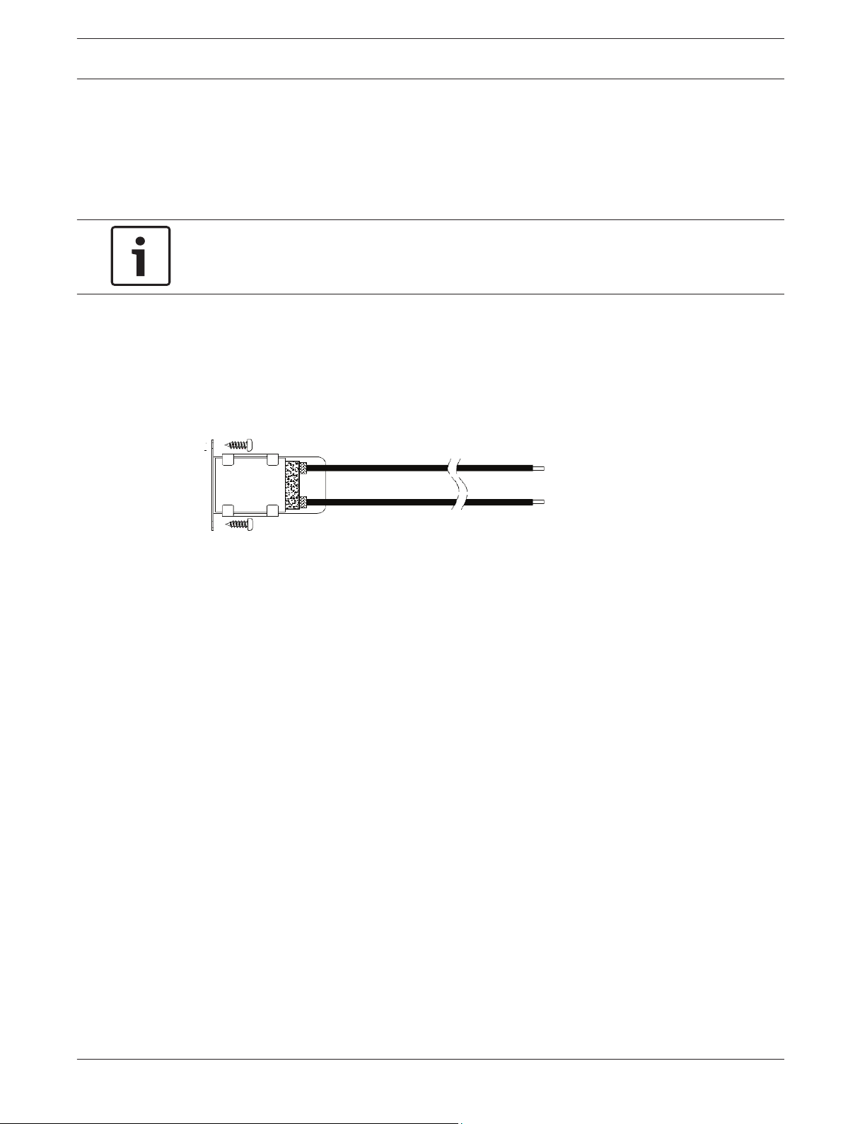
Photo Beam 5000/3000 Series Heater General description | en 5
2
General description
The BH12T heater is a heating device for ISC-FPB1-xxx family Photoelectric Beam Detectors. It
helps to prevent frost build-up on beam optical modules and covers to ensure stable
performance in harsh environmental conditions. The ceramic heater element automatically
maintains constant temperature.
Notice!
Review the warnings and safety precaution notices in this document to prevent potential
injury or product damage.
Parts list
The BH12T heaters are shipped from the factory with the following parts:
– Heaters (2)
– Heater mounting screws (4)
– Installation instructions
Figure 2.1: Heater components
Bosch Security Systems, Inc. Installation Guide 2015.07 | 01 | F.01U.315.476
Page 6

6 en | Wiring Photo Beam 5000/3000 Series Heater
3
Wiring
This section includes wiring procedures and supported wiring lengths. Supported wiring
lengths are 0.65 mm to 1.2 mm diameter (22 to 16 AWG).
The following table lists parameters that are calculated based on most common wire types
and specifications.
Notice!
Distances indicated in the table below are maximum single unit specific values. For example,
if you are using a wire diameter of 0.65 mm at 12 VDC, your maximum wiring distance
allowed is 10 meters. Divide the given distance by the number of detector sets when more
than one set of heaters is connected to the power supply.
Maximum wiring distances for 1 heater
Metric parameters
Wire diameter 12 VDC 24 VDC 28 VDC
0.65 mm 10 m 98 m 127 m
0.90 mm 21 m 192 m 249 m
1.29 mm 39 m 351 m 455 m
Imperial Unit parameters
Wire gauge 12 VDC 24 VDC 28 VDS
22 AWG 33 ft 321 ft 417 ft
19 AWG 69 ft 630 ft 817 ft
16 AWG 128 ft 1151 ft 1492 ft
Table 3.1: Wiring information
Use separate power supplies for the detector and the heater to avoid the unstable operation
caused by dynamic voltage drop during power-up. Use a battery backup type power supply
preferably with an adjustable supply voltage level. Use a power supervision relay to indicate
AC MAINS fail and/or low battery condition to the security control panel.
Perform the following steps as each installation is different and various cable types have
slightly different electrical parameters:
– Measure the impedance of the type of cable you plan to use. It is easiest to use a 100 m
or 100 ft wire section for your measurement. Short one end of the wire pair of the cable
and measure the total resistance on the other end. Use the measure value as basis to
calculate each wire section.
Notice!
If the wire is damaged or strained during installation, the impedance of the wire might be
higher than calculated or measure when operating current is drawn by the heaters.
2015.07 | 01 | F.01U.315.476 Installation Guide Bosch Security Systems, Inc.
Page 7

Photo Beam 5000/3000 Series Heater Wiring | en 7
When possible, use a cable with at least two extra unused wires in case the resistance value
must be reduced. In such case, connect each of the two extra wires in parallel with each of
the power supply lines splitting the current on the wires and significantly reduce the
resistance and corresponding voltage drop level.
– Apply Kirchhoff’s Current Law (KCL) and Voltage Law (KVL) to estimate the voltage drops
on each wire section, in case multiple heaters are daisy chained on one cable pair.
Notice!
Use caution when the calculated values result in parameters close to minimum voltage levels
and/or maximum length and current draw parameters. Over-calculate the results by 15 to
20% when determining the appropriate cable size. This is to eliminate the risk of insufficient
power levels due to differences between calculated, simulated and real installation electrical
parameters.
– Calculate the maximum overall inrush current of all heaters on the wire and select a
power supply which allows the necessary short term high current levels without
regulating the voltage level or limiting the output current.
– Measure the maximum voltage level of the power supply unit while the AC MAINS power
is connected and the batteries are charging.
– Measure the voltage level of the power supply unit while the AC MAINS power is
disconnected and the batteries supply the voltage to the power supply.
– Measure the voltage level of the power supply unit while the AC MAINS power is
disconnected and the batteries supply the voltage to the power supply.
– Apply a resistive load that draws approximately the same or similar current as the heaters
would on the wire. Let the power supply run for 10 minutes on batteries only. Measure
the voltage level of the power supply unit while the AC MAINS power is disconnected and
the batteries supply the voltage to the power supply.
– Some intelligent power supplies up-convert the battery voltage to maintain the
required voltage level while the voltage of the individual batteries is gradually
decreasing. Such power supplies might provide shorter backup power time to
maintain sufficient output power levels.
– Compare the voltage levels measured:
– When the AC MAINS power is on
– When the AC MAINS power is momentarily off
– When the AC MAINS power is off for 10 minutes
These measurements provide a good indication on how the voltage drop changes on the
heater power line in case of a power outage. Make sure the cable size calculation allows the
heaters to have sufficient power levels while the power supply is running on backup batteries
for a longer period of time. These parameters also provide sufficient information to calculate
the necessary backup battery capacity.
Bosch Security Systems, Inc. Installation Guide 2015.07 | 01 | F.01U.315.476
Page 8

8 en | Installation Photo Beam 5000/3000 Series Heater
4
4.1
Installation
Use the terminal mounting screws to attach the terminal to the beam detector. It is
recommended to mount the heaters onto the detector on a flat, horizontal surface before you
bring the device to the final mounting location. Observe the orientation of the device on the
figures below and make sure the metal plate is facing towards the optical module.
Mounting inside the ISC-FPB1-WxxDS type dual beam detectors
Refer to the following for installation information.
Compatible devices
– ISC-FPB1-W30DS
– ISC-FPB1-W60DS
– ISC-FPB1-W90DS
Refer to the following figure for securing the wires under the plastic tabs.
Figure 4.1: Wire insertion under plastic tab
4.2
Mounting inside the ISC-FPB1-WxxxQS/QF type quad beam detectors
The heater is mounted directly on the optical unit housing of the quad beam detector. Refer to
the installation instructions of the compatible photobeams for installation information.
Notice!
If the heater is installed after the beam detector is mounted and operational (retrofit
applications), perform an optical alignment procedure to ensure proper functionality.
2015.07 | 01 | F.01U.315.476 Installation Guide Bosch Security Systems, Inc.
Compatible devices
– ISC-FPB1-W60QS
– ISC-FPB1-W120QS
– ISC-FPB1-W200QS
Page 9

Photo Beam 5000/3000 Series Heater
– ISC-FPB1-W60QF
– ISC-FPB1-W120QF
– ISC-FPB1-W200QF
Refer to the following figure for securing the wires under the plastic tabs.
Installation | en 9
Figure 4.2: Left: upper optical module; right: lower optical module
Bosch Security Systems, Inc. Installation Guide 2015.07 | 01 | F.01U.315.476
Page 10

10 en | Characteristics Photo Beam 5000/3000 Series Heater
5
5.1
Characteristics
Refer to the following information for heater specification information.
12 VDC current draw and temperature characteristics
Supply voltage Outside temperature Inrush current Operating current
12 VDC 25℃ (77℉) 182 mA 40 mA
0℃ (32℉) 263 mA 90 mA
-25℃ (-13℉) 280 mA 110 mA
Figure 5.1: Left: 12VDC at 25℃ (77℉) with Current Draw over time (in minutes); right: Heater Temperature
over time (in minutes)
Figure 5.2: Left: 12VDC at 0℃ (32℉) with Current Draw over time (in minutes) ; right: Heater Temperature
over time (in minutes)
Figure 5.3: Left: 12VDC at -25℃ (-13℉) with Current Draw over time (in minutes) ; right: Heater
Temperature over time (in minutes)
2015.07 | 01 | F.01U.315.476 Installation Guide Bosch Security Systems, Inc.
Page 11

Photo Beam 5000/3000 Series Heater Characteristics | en 11
5.2
24 VDC current draw and temperature characteristics
Supply voltage Outside temperature Inrush current Operating current
24 VDC 25℃ (77℉) 407 mA 30 mA
0℃ (32℉) 600 mA 60 mA
-25℃ (-13℉) 600 mA 90 mA
Figure 5.4: Left: 24 VDC at 25℃ (77℉) with Current Draw over time (in minutes); right: Heater Temperature
over time (in minutes)
Figure 5.5: Left: 24 VDC at 0℃ (32℉) with Current Draw over time (in minutes); right: Heater Temperature
over time (in minutes)
Figure 5.6: Left: 24 VDC at -25℃ (-13℉) with Current Draw over time (in minutes); right: Heater
Temperature over time (in minutes)
Bosch Security Systems, Inc. Installation Guide 2015.07 | 01 | F.01U.315.476
Page 12

Page 13

Page 14

Bosch Security Systems, Inc.
130 Perinton Parkway
Fairport, NY 14450
USA
www.boschsecurity.com
© Bosch Security Systems, Inc., 2015
Bosch Sicherheitssysteme GmbH
Robert-Bosch-Ring 5
85630 Grasbrunn
Germany
 Loading...