

Bosch 660 EF, 660 EFO User Manual
Installation must conform with local codes, or in the absence of local codes, the National Fuel Gas Code,
ANSI Z223.1/NFPA 54.
When applicable, installation must conform with the Manufactured Home Construction and Safety Standard, Title 24 CFR, Part
3280 or the Canadian Standard CAN/CSA-Z240 MH Mobile Homes, Series M86. (660 EFO only)
SBA8517
660 EF/EFO
INDOOR MODEL/OUTDOOR MODEL
INDOOR MODEL 660 EF- Natural Gas/Liquefied Petroleum (LP) Gas
OUTDOOR MODEL
660 EFO- Natural Gas/Liquefied Petroleum (LP) Gas
6 720 644 063 (2010/03) US/CA
Warning: If the information in this manual is not
followed exactly, a fire or explosion may result
causing property damage, personal injury or death.
Do not store or use gasoline or other flammable
vapors and liquids in the vicinity of this or any other
appliance.
Improper installation, adjustment, alteration,
service or maintenance can cause injury or
property damage. Refer to this manual. For
assistance or additional information consult a
qualified installer, service agency or the gas
supplier.
In the Commonwealth of Massachusetts this
product must be installed by a licensed plumber or
gas fitter.
Upon completion of the installation, these
instructions should be handed to the user of the
appliance for future reference.
What to do if you smell gas
• Close gas valve. Open windows.
• Do not try to light any appliance.
• Do not touch any electrical switch; do not use any
phone in your building.
• Immediately call your gas supplier from a neighbor’s
phone. Follow the gas supplier’s instructions.
• If you cannot reach your gas supplier, call the fire
department.
• Installation and service must be performed by a
qualified installer, service agency or the gas supplier.

6 720 644 063
2
Index
Index
1 Important Safety Information 3
2 Appliance details 7
2.1 Features 7
2.2 Specifications (Technical data) 8
2.3 Before Installation 9
2.4 Dimensions (660 EF) 10
2.5 Dimensions (660 EFO) 10
3 Installation instructions 11
3.1 Specialized tools 11
3.2 Introduction 11
3.3 Venting (660 EF only) 11
3.4 Combustion air requirements 15
3.5 Choosing Installation Site 17
3.6 Installation Clearances 18
3.7 Installation 19
3.8 Gas piping 21
3.9 Water piping 24
3.10 Water Treatment 25
3.11 Plumbing Applications 27
4 Electrical Wiring 28
4.1 Electrical wiring 28
4.2 Remote Controller 29
4.3 Remote Controller Installation Guide 30
5 Operation instructions 33
5.1 Trial Operation 33
5.2 Initial Operation 33
5.3 How to Use
(Not using the remote controller) 34
5.4 How to Use (Using the remote controller) 35
6 Maintenance and service 37
6.1 Regular Maintenance 37
6.2 Preventing Damage from Freezing 38
7 Troubleshooting 40
7.1 Initial Operation 40
7.2 Temperature 40
7.3 Amount of Hot Water 41
7.4 Remote Controller 42
7.5 Sounds 42
7.6 Others 43
7.7 Check for an Error Code
(Using the remote controller) 44
8 Follow- up Service 45
8.1 Requesting Service 45
8.2 Gas conversion 45
9 Interior components diagram 46
9.1 660 EF Interior components 46
9.2 660 EFO Interior components 47
10 Protecting the environment 48
11 Limited Warranty 49
6 720 644 063
Important Safety Information
3
1 Important Safety Information
To prevent damage to property and injury to the user,
the icons shown below will be used to warn of varying
levels of danger. Every indication is critical to the safe
operation of the water heater and must be understood
and observed. Potential dangers from accidents during
installation and use are divided into the following four
categories. Closely observe these warnings; they are
critical to your safety.
Icons warning of risk level
CAUTION used without the safety alert symbol indicates a potentially hazardous situation which, if not
avoided, may result in property damage.
Attention Installers
• In order to use the water heater safely, read this
installation manual carefully, and follow the installation instructions.
• Failures and damage caused by erroneous work or
work not as instructed in this manual are not covered
by the warranty.
• Check that the installation was done properly in
accordance with this Installation Manual upon
completion.
• After completing installation, please either place this
Installation Manual in a plastic pouch and attach it to
the side of the water heater (or the inside of the pipe
cover or recess box if applicable), or hand it to the
customer to retain for future reference.
Fig. 1
This is the safety alert symbol. It is used
to alert you to potential personal injury
hazards. Obey all safety messages that
follow this symbol to avoid possible
injury or death.
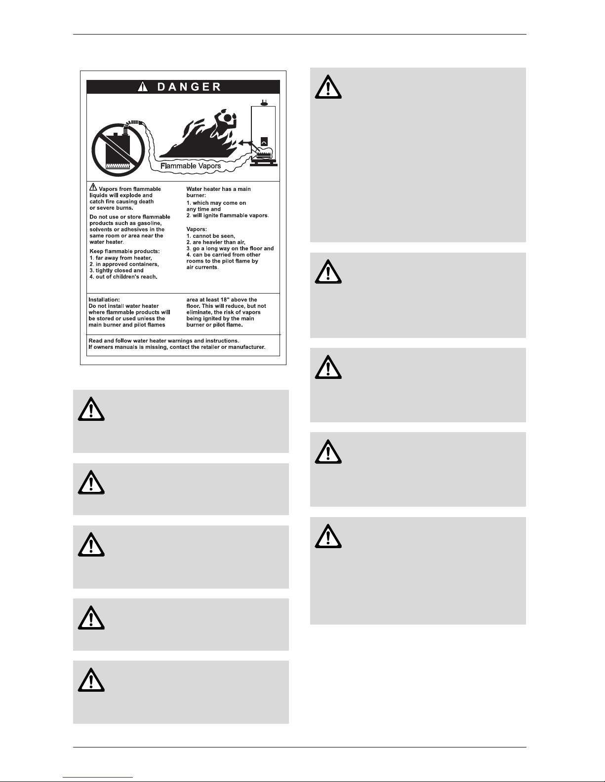
Danger: DANGER indicates an
imminently hazardous situation which, if
not avoided, will result in death or
serious injury.
Warning: WARNING indicates a
potentially hazardous situation which, if
not avoided, could result in death or
serious injury.
Caution: CAUTION indicates a
potentially hazardous situation which, if
not avoided, may result in minor or
moderate injury.
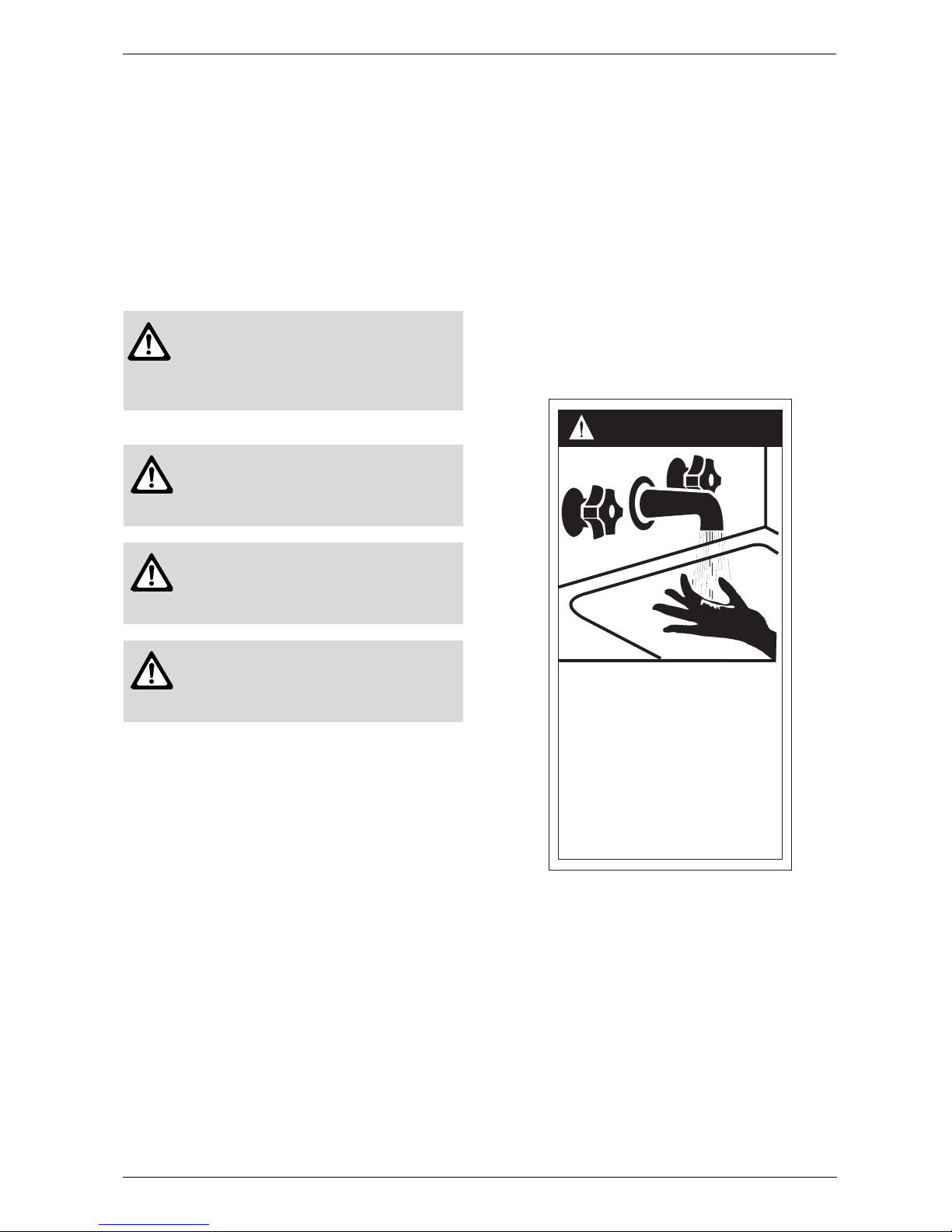
HOT
BURN
DANGER
Water temperature over 125°F can
cause severe burns instantly or
death from scalds.
Children, disabled and elderly are
at highest risk of being scalded.
See instruction manual before
setting temperature at water
heater.
Feel water before bathing or
showering.
6 720 644 063
4
Important Safety Information
Fig. 2
Danger: [660 EF] - do not install
outdoors!
Do not use the water heater if the exhaust pipe is displaced, has holes, is
clogged or is corroded.
Danger: [660 EFO] - do not install
indoors!
This will cause carbon monoxide poisoning and a potential fire hazard.
Danger: Do not allow anyone to
change the water temperature while hot
water is being used!
To prevent scalding, do not change the
water temperature to a higher setting.
Warning: If the information in this
manual is not followed exactly, a fire or
explosion may result causing property
damage, personal injury or death.
Warning: This water heater does not
have a pilot. It is equipped with an ignition device that automatically lights the
burner. Do not try to light the burner by
hand.
Warning: BEFORE OPERATING
smell all around the water heater area
for evidence of leaking gas. Be sure to
smell next to the floor because some
gas is heavier than air and will settle on
the floor.
WHAT TO DO IF YOU SMELL GAS:
- Do not try to light any appliance.
- Do not touch any electrical switch; do
not use any phone inyour building.
- Immediately call your gas supplier from
a neighbor’s phone. Follow the gas supplier’s instructions.
- If you cannot reach your gas supplier,
call the fire department.
Warning:
Use only your hand to turn the gas valve
knob. Never use tools. If the knob will
not turn by hand, don’t try to repair it.
Call a qualified service technician.
Force or attempted repair may result in
a fire or explosion.
Warning:
Do not use this water heater if any part
has been under water. lmmediately call
a qualified service technician to inspect
the water heater and to replace an damaged parts.
Warning:
When a gas leak is noticed:
1. Stop use immediately
2. Close the gas valve
3. [When installing indoors] Open windows and doors.
Warning:
If you detect abnormal combustion or
abnormal odors, or during an earthquake, tornado or fire:
1. Turn off the hot water supply
2. Turn off the power to the water heater
3. Turn off gas and water supply valve.
4. Call the nearest Bosch agent.
6 720 644 063
Important Safety Information
5
Warning: Explosion Hazard!
If the temperature and pressure relief
valve is dripping or leaking, have a qualified service technician replace it. Do
not plug or remove the valve. Failure to
follow these instructions can result in
fire or explosion, and personal injury or
death.
Warning:
Check the temperature of the running
hot water before entering the shower.
Check the temperature before stepping
into the bath tub.
Warning:
Do not place the exhaust vent terminal
in an indoor environment by means of
adding walls and ceiling (do not enclose using corrugated sheets, etc.).
Carbon monoxide poisoning or fire may
occur as a result.
Warning:
Leave the proper clearance between
the water heater and nearby objects
(trees, timber, boxes with flammable
materials etc.).
Warning:
Do not use combustible chemicals
such as oil, gasoline, benzene etc. in
the near the heater or the exhaust vent
terminal.
Warning:
Do not place combustibles such as
laundry, newspapers, oils etc. near the
heater or the exhaust vent terminal.
Warning: [660 EF only]
Carbon Monoxide Poisoning Hazard.
Do not install this water heater in a mobile home, recreation vehicle or on a
boat.
Warning: [660 EFO only]
Carbon Monoxide Poisoning Hazard.
Do not install this water heater in a recreation vehicle or on a boat.
Warning:
Do not store or use gasoline or other
flammable vapors and liquids in the vicinity of this or any other appliance.
Warning:
Do not place or use a spray can near
the heater or the exhaust vent terminal.
Warning:
Installation and service must be performed by a qualified installer, service
agency or the gas supplier.
Warning: [When installing indoors
660 EF]
Check the air supply vent for dust or obstructions.
Warning:
If this unit will be installed in a beauty
salon or other location where hair spray
or aerosols will be used, locate the unit
in a separate area that is supplied with
fresh air from outdoors.
Warning:
Do not use hair spray or spray detergent in the vicinity of the heater.
Warning:
Do not allow small children to play unsupervised in the bathroom. Do not allow small children to bathe
unsupervised.
Warning:
Do not touch the powercord with wet
hands.
Warning:
Consult the nearest Bosch agent if the
water heater location needs to be
changed.
Warning:
Contact a qualified service technician
for any necessary repairs, service or
maintenance.
6 720 644 063
6
Important Safety Information
Warning:
Contact Bosch before using with a solar pre-heater.
Warning:
California Proposition 65 lists chemicalsubstances known to the state to cause
cancer, birth defects, death, serious illness or other reproductive harm. This
product may contain such substances,
be their origin from fuel combustion
(gas, oil) or components of the product
itself.
Warning:
The gas conversion kit shall be installed
by a qualified service agency in accordance with the manufacturer’s instructions and all applicable codes and
requirements of the authority having jurisdiction. The information in the instructions must be followed to minimize the
risk of fire or explosion or to prevent
property damage, personal injury, or
death. The qualified service agency is
responsible for the proper installation of
this kit. The installation is not proper
and complete until the operation of the
converted appliance is checked as
specified in the manufacturer’s instructions supplied with the kit.
Caution:
Be sure to electrically ground the unit.
Caution:
Keep power cord free of dust.
Caution:
Do not use the water heater for other
than hot water supply, shower and bath.
Caution:
Do not use a broken or modified power
cord. Do not bind, bend or stretch power cords. Do not scratch, modify, or
subject them to impact or force.
Caution:
To prevent burns or scalding, turn off
the power button or power supply and
wait until the equipment cools before
performing maintenance.
Caution:
Do not turn off the water heater while
someone is bathing.
Caution:
Do not cover the water heater and the
exhaust vent terminal, store trash or debris near it, or in any way block the flow
of fresh air to the unit.
Caution:
Do not install in locations where excessive dust or debris will be in the air.
Caution:
Do not touch the exhaust vent (pipe, terminal) during or immediately after operation of the water heater.
Caution:
Do not drink water that has been inside
the unit for an extended period of time.
Do not drink the first use of hot water
from the unit in the morning.
Caution:
Clean the filter on the water inlet as frequently as required by the quality of
your local water.
Caution:
Keep the area around the unit clean. If
boxes, weeds, cobwebs, cockroaches
etc. are in the vicinity of the unit,
damage or fire can result.
Caution:
Do not install the equipment where the
exhaust will blow on walls or windows.
Caution:
Treat hard, acidic or otherwise impure
supply water with approved methods to
ensure full warranty coverage.
Caution:
Problems resulting from scale formation
are not covered by the warranty.
Caution:
Check ignition during use and extinction after use.
6 720 644 063
Appliance details
7
2 Appliance details
2.1 Features
Parts included with the unit
• Tapping Screw
• Installation Manual/user manual with warranty inside
(this document)
• Cross Recess Head Screw (660 EFO NG, 660 EFO
LP)
• Power Cord (660 EF NG, 660 EF LP).
Accessories (Bosch part #)
• Optional Remote Control to operate with the appliance BRC01US for USA, BRC01CA for Canada
• Isolation Valves (includes pressure relief valve)
• Remote Controller Outdoor Junction Box (BOJB)
• Remote Controller cord 3m (10ft) BRC10CORD
• Remote Controller cord 8m (26ft) BRC26CORD
• Recess Box BRBKIT (for 660 EFO only)
• Pipe Cover (BPCKIT).
Caution:
Do not run water through the unit
when unit is not on. When discharg-
ing hot water, make sure the unit is ON.
If water is run through the unit with the
unit OFF, water may condense inside
the unit and cause incomplete combustion or damage to the internal electrical
components. For single-handle fixtures
or valves, discharge water setting the
handle completely to the water side.
Caution:
This unit is only approved for installation
up to 1350m (4500 ft.) above sea level.
For installations at higher elevations,
contact Bosch Thermotechnology
Corp. for Instructions.
Caution:
Do not disassemble the remote controller. Do not use benzene, oil or fat detergents to clean the remote controller.
This may cause deformation. Do not get
the remote controller wet. Although it is
water resistant, too much water can
cause damage. Do not splash water on
the remote controller. Do not expose
the remote controller to steam. Do not
locate the remote controller near stoves
or ovens, this may cause damage or failure.
Caution:
Preventing damage from freezing (see
section 6.2). Damage can occur from
frozen water within the device and
pipes even in warm environments. Be
sure to read below for appropriate
measures. Repairs for damage caused
by freezing are not covered by the warranty.
Caution:
Take necessary measures to prevent
freezing of water and leakage of gas
when leaving the unit unused for long
periods of time (see section 6.2).
Caution:
If it is snowing, check the air inlet, exhaust gas vent and exhaust vent terminal for blockage.
Caution:
Do not use parts other than those
specified for this equipment.
i
BOSCH is constantly improving its products, therefore specifications are subject
to change without prior notice.

6 720 644 063
8
Appliance details
2.2 Specifications (Technical data)
Approved in US/Canada
Capacity
Maximum flow rate: 5.3 GPM (20 l/min) at a 45°F
(25°C) rise.
Maximum Input
140,000 Btu/h (41,03 kW)
Minimum Input
20,000 Btu/h (5.67 kW)
Temperature Control
Selection range: 100°F (37°C) - 160°F (70°C)
Default temperature: 120°F (50°C)
Temperature Settings using the remote controller:
USA
100- 150 °F (5°F intervals), 160 °F
Canada
37-48°C (In 1°C intervals), 50-70°C (In 5°C intervals)
Gas Requirement
Gas connection (inches) - ¾”
Inlet gas pressure under operation (with a high hot
water flow rate)
• Propane: 8” - 14” water column
• Natural Gas: 4” - 10.5” water column.
Power Supply Consumption
• Freeze Prevention 141W.
Water
• Hot water connection (inches) - ¾”
• Cold water connection (inches) - ¾”
• Minimum water flow: 0.5 gallon/minute (2 l/m)
Note: The capacity may differ slightly, depending on
the water pressure, water supply, piping conditions,
and water temperature
• Water pressure recommend: 29 to 70 psi
• Connections:
– Bottom of heater
Dimensions
• Depth (in): 6.7” (170 mm)
• Width (in): 13.8” (350 mm)
• Height (in): 20.5” (520 mm)
• Weight: 36 pounds (16.3 kg).
Gas types
Natural Gas.
LP Gas.
Voltage
120 V AC (60 Hz) nominal
Safety devices
• Flame Rod
•Thermal Fuse
• Lightning Protection Device (ZNR)
• Overheat Prevention Device
• Freezing Prevention Device
• Fan Rotation Detector.
i
If this water heater is being installed at an
elevation of 2,000' (610m) or higher,
disconnect the connector labeled "High
Elevation Disconnect". This connector is
located inside the unit.
6 720 644 063
Appliance details
9
2.3 Before Installation
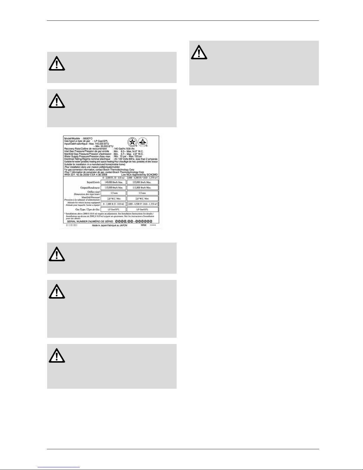
Fig. 3 Ex. For LP Gas 660 EFO
Danger: Checkup!
Check the fixing brackets and vent pipe
yearly for damage or wear. Replace if
necessary.
Danger: Check the gas!
- Check that the rating plate indicates
the correct type of gas.
- Check that the gas supply line is sized
for 140,000 BTU for 660 EF, 660 EFO.)
Warning: Check the power!
The power supply required is 120VAC,
at 60Hz. May result in fire or electric
shock.
Warning: Use Extreme Caution if Using With a Solar Pre-Heater!
Using this unit with a solar pre-heater
can lead to unpredictable output temperatures and possibly scalding. If absolutely necessary, use mixing valves to
ensure output temperatures do not get
to scalding levels.
Caution: Do Not Use Equipment for
Purposes Other Than Those Specified!
Do not use for other than increasing the
temperature of the water supply, as unexpected accidents may occur as a result.
Caution: Check Water Supply Quality!
If the water supply is in excess of 6
grains per gallon (100 mg/L) of hardness, acidic or otherwise impure, treat
the water with approved methods in order to ensure full warranty coverage.

6 720 644 063
10
Appliance details
2.4 Dimensions (660 EF)
Fig. 4 Dimensions
2.5 Dimensions (660 EFO)
Fig. 5 Dimensions
6 720 644 063
Installation instructions
11
3 Installation instructions
3.1 Specialized tools
The following specialized tools may be required for
installation:
• Manometer
• Multimeter
• Combustion Gas Analyzer.
3.2 Introduction
Please follow these instructions. Failure to follow
instructions may result in:
B Damage or injury.
B Improper operation.
B Loss of warranty.
3.3 Venting (660 EF only)
3.3.1 Vent piping
• Bosch Vent System is suggested for the vent system.
If Bosch Vent is not used, a UL listed category III
ventsystem must be used
• Follow the vent pipe manufacturer's installation
instructions.
• Make the vertical section of the exhaust ventas short
as possible
• Maintain the same vent pipe diameter from the heater
flue to the vent termination.
Clearances
Clearances vary by manufacturer, refer to the UL
approved clearances when using materials other than
Bosch Vent System.
• The first vertical run from the top of the heater should
be no longer than 0.9m (3')
• Make sure vent pipe is gas tight and will not leak. Use
silicon sealant wherever necessary
• Do not common vent or connect more than one appliance to this venting system
• The total vent length including horizontal & verticalvent runs should be no less than 3' (0.9m).
• Do not store hazardous or flammable substances
near the vent termination and check that the termination is not blocked in any way
• Steam or condensed water may come out from the
vent termination. Select the location for the termination so as to prevent injury or property damage
• If snow is expected to accumulate, take care the end
of the pipe is not covered with snow or hit by falling
lumps of snow
• Consult the vent pipe manufacturer's installation
instructions for chimney connections.
Appliance Adapters
When using a vent system other than Bosch Vent, an
appliance adapter will be required to properly connect
the vent to this appliance. Consult the manufacturer's
instructions for the proper appliance adapter.
Warning: The water heater must be
installed by a qualified installer in
accordance with these instructions. If
improperly installed, a hazardous condition
such as explosion or carbon monoxide
poisoning could result. Bosch
Thermotechnology Corp. is not
responsible for improperly installed
appliances.
Warning:
CARBON MONOXIDE POISONING!
Follow all vent system requirements in accordance with relevant local or state regulation,or, in the absence of local or state
code, in the U.S. to the National Fuel Gas
Code ANSIZ233.1/NFPA 54 – latest edition, and in Canada, in accordance with
NSCNGPI.
660 EF
Pipe diameter 3’’ (75mm)
Table 1
No. of elbows Max. Straight Vent Length
1)
1) Not including the termination.
3 15' (4.5m)
2 25' (7.5m)
1 35' (10.6m)
Table 2
Manufacturer
and Product
Enclosed Unenclosed
Hort. Vert. Hort. Vert.
Bosch Vent
System
10" (250mm) (sides)
15" (375mm) (top)
6" (150mm) (bottom)
4"
(100mm)
1"
(25mm)1"(25mm)
Table 3
6 720 644 063
12
Installation instructions
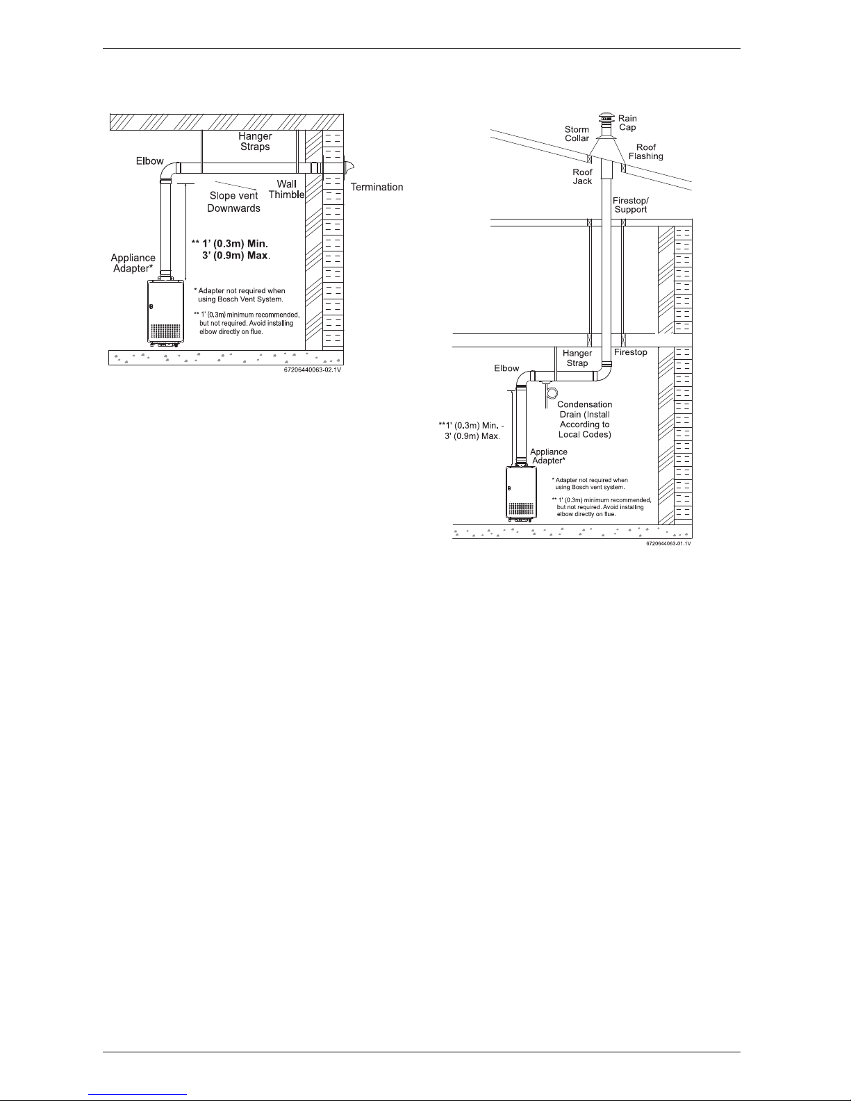
Horizontal Vent Termination
Fig. 6
• Terminate at least 12" (300mm) above grade or
above snow line.
• Terminate at least 7' (2.1m) above a public walkway,
6' (1.8m) from the combustion air intake of any appliance, and 3' (0.9m) from any other building opening,
gas utility meter, service regulator etc.
• Terminate at least 3' (0.9m) above any forced air inlet
within 10' (3m), 4' (1.2m) below, 4' (1.2m) horizontally from or 1' (0.3m) above any door, window, or
gravity air inlet into any building per National Fuel
Gas Code ANSI Z223.1/NFPA 54.
• Slope the horizontal vent 1/4" downwards for every
12" (300mm) toward the termination.
• In the Commonwealth of Massachusetts a carbon
monoxide detector is required for all side wall horizontally vented gas fuel equipment.
Vertical Vent Termination
Fig. 7
• Terminate at least 6' (1.8m) from the combustion air
intake of any appliance, and 3' (0.9m) from any other
building opening, gas utility meter, service regulator
etc.
• Enclose exterior vent systems below the roofline to
limit condensation and protect against mechanical
failure.
• When the vent penetrates a floor or ceiling and is not
running in a fire rated shaft, a firestop and support is
required.
• When the vent termination is located not less than 8'
(2.4m) from a vertical wall or similar obstruction, terminate above the roof at least 2' (0.6m), but not more
than 6' (1.8m), in accordance with the National Fuel
Gas Code ANSI Z223.1/NFPA 54.
• Provide vertical support every 12' (3.6m) or as
required by the vent pipe manufacturer's instructions.
• Slope the horizontal vent 1/4" for every 12" (300mm)
towards the drain tee.
• A short horizontal section is recommended to prevent debris from falling into the water heater.
• Install a condensation drain in the horizontal section
of the venting. For installations in tight spaces where
there is not enough room to install two elbows and a
horizontal drain tee, a vertical drain tee may be substituted.
6 720 644 063
Installation instructions
13
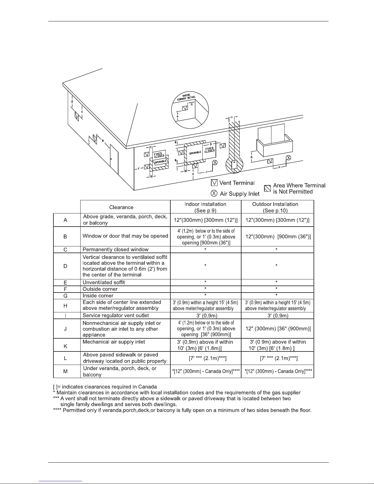
Clearance Requirements from Vent Terminations to Building Openings
*All clearance requirements are in accordance with ANSI Z21.10.3 and the National Fuel Gas Code, ANSI Z223.1
and in Canada, in accordance with NSCNGPIC.
Fig. 8
6 720 644 063
14
Installation instructions
3.3.2 Clearance Requirements from Vent Terminations to Building Openings
All clearance requirements are in accordance with ANSI
Z21.10.3 and the National Fuel Gas Code, ANSI
Z223.1 and in Canada, in accordance with
NSCNGPIC.
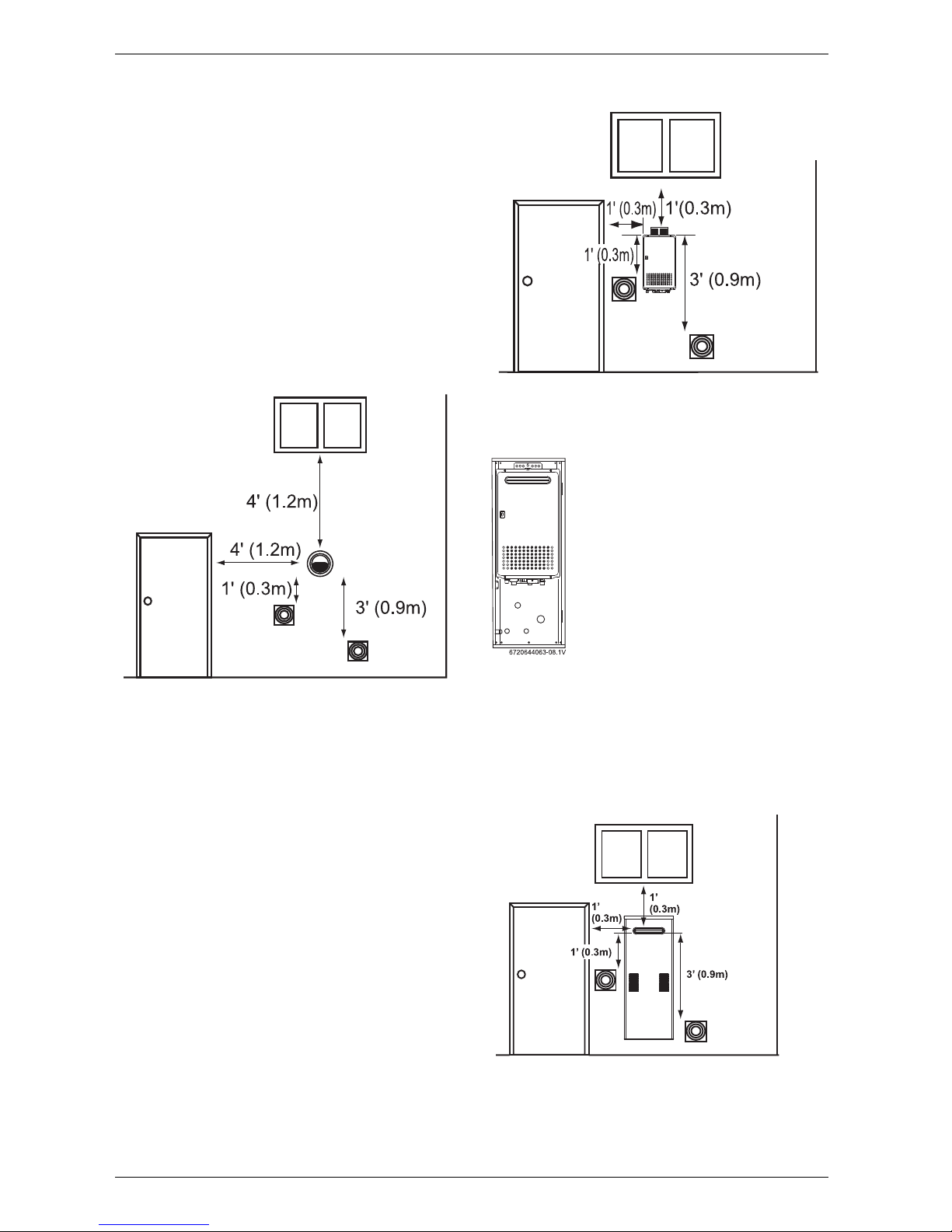
Vent Clearances When Heater is Installed
Indoors (For 660 EF appliance)
Maintain the following clearances to any opening in any
building:
• 4' (1.2m) below, 4' (1.2m) horizontally from, or 1'
(0.3m) above any door, operable window, or gravity
air inlet into any building. 3' (0.9m) above any forced
air inlet within 10' (3m).
Fig. 9
For Installations in Canada, clearances are as follows:
To windows, doors, & gravity air inlets: 36" (900mm). To
forced air inlets: 6' (1.8m). These clearance requirements hold true for all of the above situations: Indoor.
Outdoor Clearances to Opening into any Building
(For 660 EFO appliance)
Maintain the following clearances to any opening in any
building:
• 1' (0.3m) below, 1' (0.3m) horizontally from, or 1'
(0.3m) above any door, operable window, or gravity
air inlet into any building. 3' (0.9m) above any forced
air inlet within 10' (3m).
Fig. 10
Vent Clearances When Heater is Installed in a
Recess Box (For 660 EFO appliance)
Fig. 11 Recess box installation with cover removed
Maintain the following clearances to any opening in any
building:
• 1' (0.3m) below, 1' (0.3m) horizontally from, or
1' (0.3m) above any door, operable window, or gravity air inlet into any building. 3' (0.9m) above any
forced air inlet within 10' (3m).
Fig. 12
For Installations in Canada, clearances are as follows:
To windows, doors, & gravity air inlets: 36" (900mm).
To forced air inlets: 6' (1.8m).
6 720 644 063
Installation instructions
15
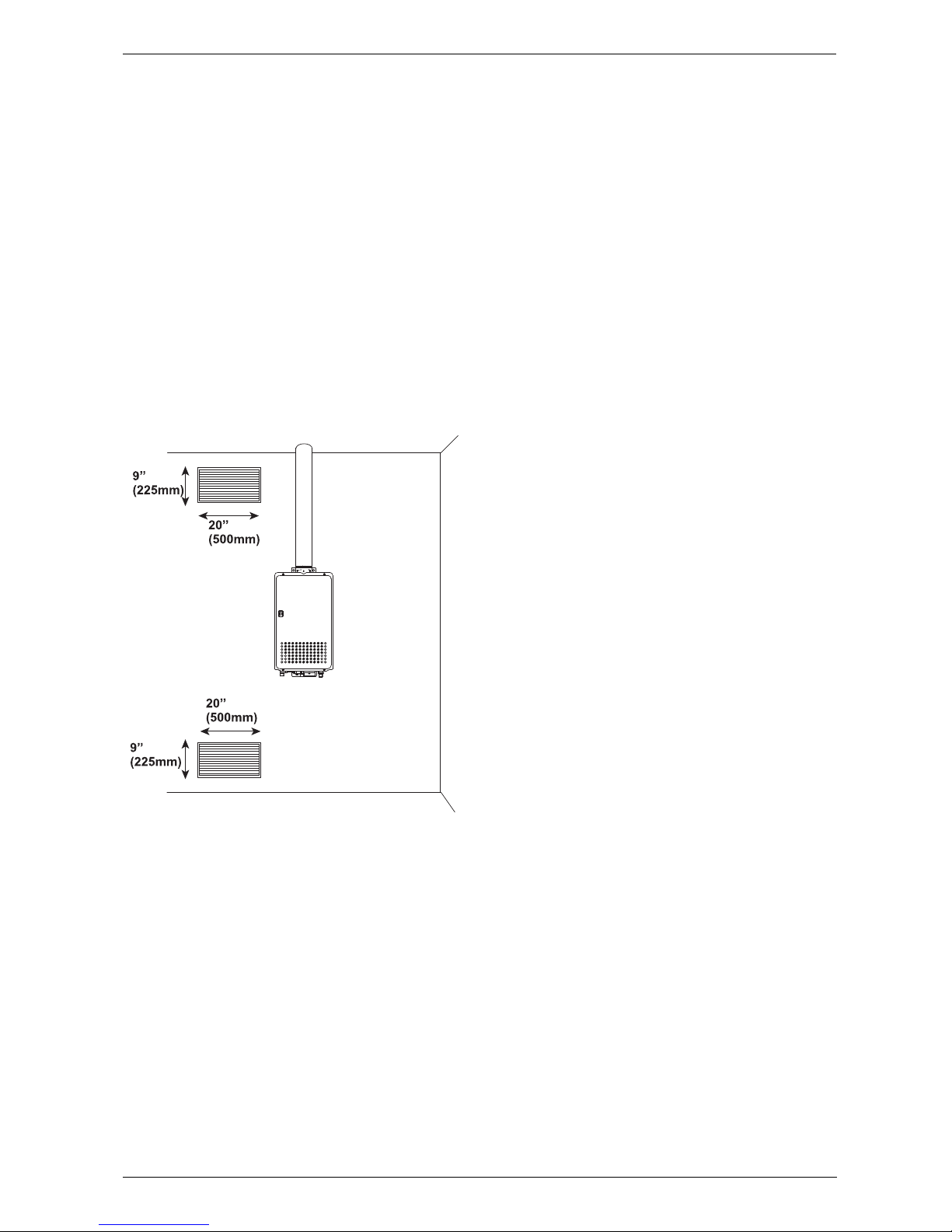
3.4 Combustion air requirements
Combustion Air
Supply combustion air to the units as per the National
Fuel Gas Code, ANSI Z223.1 and in Canada, in
accordance with NSCNGPIC.
• Provide two permanent openings to allow circulation
of combustion air.
• Make each opening 180 square inches if they provide indoor air, and 100 square inches for outdoor
air.
• If the unit is installed in a mechanical closet, provide
a 24" (600mm) clearance in front of the unit to the
door.
• If combustion air will be provided through a duct, size
the duct to provide 60 cubic feet of fresh air per
minute.
Fig. 13

6 720 644 063
16
Installation instructions
Attention residents of the Commonwealth of Massachusetts:
In the Commonwealth of Massachusetts the following
regulation went into effect on 12/30/2005:
(a)For all side wall horizontally vented gas fueled
equipment installed in every dwelling, building or
structure used in whole or in part for residential
purposes, including those owned or operated by the
Commonwealth and where the side wall exhaust vent
termination is less than seven (7) feet above finished
grade in the area of the venting, including but not limited
to decks and porches, the following requirements shall
be satisfied:
1. INSTALLATION OF CARBON MONOXIDE
DETECTORS. At the time of installation of the side wall
horizontal vented gas fueled equipment, the installing
plumber or gasfitter shall observe that a hard wired
carbon monoxide detector with an alarm and battery
back-up is installed on the floor level where the gas
equipment is to be installed. In addition, the installing
plumber or gasfitter shall observe that a battery
operated or hard wired carbon monoxide detector with
an alarm is installed on each additional level of the
dwelling, building or structure served by the side wall
horizontal vented gas fueled equipment. It shall be the
responsibility of the property owner to secure the
services of qualified licensed professionals for the
installation of hard wired carbon monoxide detectors.
a.In the event that the side wall horizontally vented gas
fueled equipment is installed in a crawl space or an at
tic, the hard wired carbon monoxide detector with alarm
and battery back-up may be installed on the next
adjacent floor level.
b. In the event that the requirements of this subdivision
can not be met at the time of completion of installation,
the owner shall have a period of thirty (30) days to
comply with the above requirements; provided,
however, that during said thirty (30) day period, a
battery operated carbon monoxide detector with an
alarm shall be installed.
2. APPROVED CARBON MONOXIDE DETECTORS.
Each carbon monoxide detector as required in
accordance with the above provisions shall comply with
NFPA 720 and be ANSI/UL 2034 listed and IAS
certified.
3. SIGNAGE. A metal or plastic identification plate shall
be permanently mounted to the exterior of the building
at a minimum height of eight (8) feet above grade
directly in line with the exhaust vent terminal for the
horizontally vented gas fueled heating appliance or
equipment. The sign shall read, in print size no less than
one half (1/2) inch in size, "GAS VENT DIRECTLY
BELOW. KEEP CLEAR OF ALL OBSTRUCTIONS".
4. INSPECTION. The state or local gas inspector of the
side wall horizontally vented gas fueled equipment shall
not approve the installation unless, upon inspection, the
inspector observes carbon monoxide detectors and
signage installed in accordance with the provisions of
248 CMR 5.08(2)(a)1 through 4.
(b)EXEMPTIONS: The following equipment is exempt
from 248 CMR 5.08(2)(a)1 through 4:
1. The equipment listed in Chapter 10 entitled
"Equipment Not Required To Be Vented" in the most
current edition of NFPA 54 as adopted by the Board;
and
2. Product approved side wall horizontally vented gas
fueled equipment installed in a room or structure
separate from the dwelling, building or structure used in
whole or in part for residential purposes.
(c) MANUFACTURERS REQUIREMENTS - GAS
EQUIPMENT VENTING SYSTEM REQUIRED. When
the manufacturer of Product Approved side wall
horizontally mounted gas equipment provides a venting
system design or venting system components with the
equipment, the instructions provided by the
manufacturer for the installation of the equipment and
the venting shall include:
1. Detailed instructions for the installation of the venting
system or the venting system components: and
2. A complete parts list for the venting system design or
venting system.
(d) MANUFACTURER REQUIREMENTS - GAS
EQUIPMENT VENTING SYSTEM NOT PROVIDED.
When the manufacturer of a product approved side wall
horizontally vented gas fueled equipment does not
provide the parts for the venting of flue gases, but
identifies "special venting systems," the following
requirements shall be satisfied by the manufacturer:
1. The referenced "special venting system" instructions
shall be included with the appliance or equipment
installation instructions; and
2. The "special venting systems" shall be product
approved by the Board, and the instructions for that
system shall include a parts list and detailed installation
instructions.
(e) A copy of all installation instructions for all products
approved side wall horizontally vented gas fueled
equipment, all venting instructions, all parts lists for
venting instructions, and/or all venting design
instructions shall remain with the appliance or
equipment at the completion of the installation.
 Loading...