

Page 1
WARNING:
If the information in this manual is not followed
exactly, a re or explosion may result causing
property damage, personal injury or death.
Follow each appliance's instructions precisely.
Installation and service must be performed by a
trained and certi ed installer, service agency or the
gas supplier.
Application drawings in this manual are conceptual
only and do not purport to address all design,
installation, code, or safety considerations.
The diagrams in this manual are for reference use by
code of cials, designers and licensed installers. It is
expected that installers have adequate knowledge of
national and local codes, as well as accepted
industry practices, and are trained on equipment,
procedures, and applications involved. Drawings are
not to scale.
Refer to the appliance and accessory installation
manuals for additional detailed information!
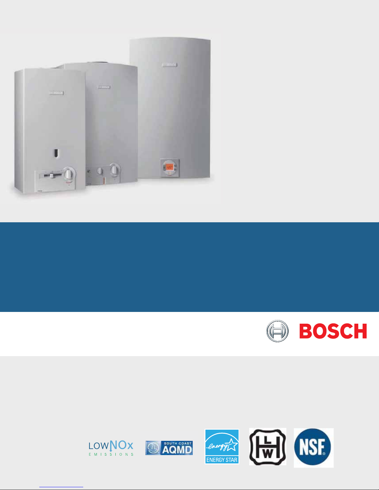
GREENTHERM & THERM
Tankless Water Heaters
C1210ES/ESC, C1050ES, C950ES, 940ES, 940ESO, 830ES, 520HN, 520PN, 330PN
Applications Manual
Page 2

|
2
THERM/GREENTHERM Tankless Water Heaters
Applications Manual
Bosch Thermotechnology Corp.Data subject to change
Page 3

Applications Manual THERM/GREENTHERM Tankless Water Heaters | 3
Table of Contents
1 Explanation of symbols 4
2 Introduction 5
3 Model Certi cations 5
4 Tankless Water Heater Accessories 6
5 Pump sizing for circulation 7
5.1 Pressure drop curves 7
5.2 Domestic hot water circulation 8
5.3 Tank loading 9
6 Water Heater Sizing & Speci cations 10
6.1 Sizing tankless water heaters 10
6.2 Tankless Water Heater Speci cations 12
7 Water Quality 14
8 Applications Legend 15
9 Domestic Hot Water Applications 16
9.1 Low volume applications 17
9.2 Whole house applications 18
10 High Volume Potable Water Heating 22
10.1 Cascading unit applications 22
10.2 Parallel unit applications 25
11 Residential Solar Applications 26
11.1 Booster applications 27
12 Commercial Solar Applications 29
13 Commercial Water Heating Applications 30
13.1 Commercial Kitchen applications 31
13.2 Tank loading with domestic hot water
recirculation 32
13.3 Advanced tank loading commercial hot
water system 33
13.4 Common Venting 34
Bosch Thermotechnology Corp.
Data subject to change
Page 4
|
4
THERM/GREENTHERM Tankless Water Heaters
1 Explanation of symbols
Warnings
Warnings in this document are identi ed by a
warning triangle printed against a grey
background.
Keywords at the start of a warning indicate
the type and seriousness of the ensuing risk if
measures to prevent the risk are not taken.
The following keywords are de ned and can be used in
this document:
f NOTICE indicates that damage to property may occur.
f CAUTION indicates that personal injury may occur.
f WARNING indicates that severe personal injury may
occur.
Applications Manual
f DANGER indicates that severe personal injury or
death may occur.
Important information
Important information in cases where there is no
risk of personal injury or material losses is identi-
ed by the symbol shown on the left. It is bordered
by horizontal lines above and below the text.
Bosch Thermotechnology Corp.Data subject to change
Page 5
Applications Manual THERM/GREENTHERM Tankless Water Heaters | 5
2 Introduction
This Applications Manual is intended to present some
of the most common applications of the Bosch Therm
tankless water heaters. Application drawings are shown
with both piping and corresponding electrical schematics
where applicable. Auxiliary equipment depicted does not
necessarily represent any one manufacturer or speci c
model number. There are a wide variety of techniques,
practices and piping strategies possible when installing
water heating appliances. It is the responsibility of the
installing contractor to determine the best solution for the
application.
NOTICE: All drawings are conceptual in nature
and do not address all design, installation or
safety considerations. Additional safety and/or
auxiliary equipment may be needed. Drawings
are for reference use by of cials, designers and
licensed installers. It is expected that installers
have adequate knowledge of accepted industry
practices for the equipment, procedures, and
applications involved. It is the responsibiltiy of
the installer to ensure that the installation is in
accordance with local building codes.
3 Model Certi cations
The following are certi cation stamps and explanations
that are speci c to one or more Bosch tankless water
heaters. These certi cations bring the appliances in accordance with the requirements of the National Fuel Gas
Code ANSI Z223.1/NFPA 54.
appliances using gas or other petroleum fuel.
appliances using gas or other petroleum fuel.
Energy Star quali ed (models C 1050 ES,
C 950 ES, 940 ES, 940 ESO, 830 ES, 660 EF,
660 EFO).
Certi ed to applicable U.S. standards for
Certi ed to applicable Canadian standards for
Although this manual covers many common applications
for our products, system possibilities are virtually endless.
Should you encounter an application that is not covered
in this manual or have any questions regarding any of its
content, we encourage you to contact your local sales
representative or us directly at Bosch Thermotechnology
Corp.
This manual is not a substitute for any of the appliance
installation manuals. All speci cations are subject to
change.
NOTICE: Installation must conform with local
codes or, in the absence of local codes, the
National Fuel Gas Code ANSI Z223.1/NFPA 54.
In Canada: Installation must conform with CGA
B149.(1,2) INSTALLATION CODES and/or local
installation codes.
National Sanitation Foundation International
certi ed.
Energy ef ciency certi ed by AHRI -
Air-Conditioning, Heating, and
Refrigeration Institute.
R
For model C 1210 ESC only.
This model is built in accordance
with the requirements of the ASME
Boiler and Pressure Vessel Code and
received the Certi cate of
Authorization from the National
Board. The heat exchanger has the
NB and the HLW stamps.
Other certi cations:
f Meets California Energy Commission (CEC) standards.
Bosch Thermotechnology Corp.
f Approved by the Commonwealth of Massachusetts.
f South Coast Air Quality Management - 2012
For Models 830 ES, 940 ES, 940ESO, C 950 ES, C 1050 ES,
C 1210 ES and C 1210 ESC only
.
Data subject to change
Page 6

|
6
THERM/GREENTHERM Tankless Water Heaters
Applications Manual
4 Tankless Water Heater Accessories
Available accessories
Part number
Concentric vent/air intake kit stainless
steel
Concentric termination kit - PVC* 196016
Exhaust/intake bird screen - PVC L2594
Vertical vent kit ES VVT
Horizontal vent kit 4TWHVK3SII
Outdoor kit for Therm 7709003913
Wireless remote control TSTAT2
Intelligent cascading kit 7709003962
High temperature kit 7736500074
PVC Condensing drain tee† 196061
Condensate neutralization cartridge kit¹ JM-2KIT
Isolation valve kit with PRV ES ISO KIT
Pipe Cover W2-3 Silver PTPCES
Recess Box for 830 ES to C 1210 ES
models
Polypropylene up and out venting kit 7738003210
Polypropylene common venting system
for up to 4 units
Meets ULC S636 Standard
*
Also included in the Concentric termination kit (196016)
†
¹ Condensate neutralization cartridge kit may be used for non-condensing product vent systems
ESHCK
7736500043
see vent
catalog
C 1210 ES /
C 1210 ESC
C 1050 ES C 950 ES 940 ES 940 ESO 830 ES
Available accessories
Part number 520 HN 520 PN 330 PN
Freeze prevention kit 7709003775
Isolation valve kit with PRV ES ISO KIT
Power vent w/back draft apper AQ4
Bosch Thermotechnology Corp.Data subject to change
Page 7
Applications Manual THERM/GREENTHERM Tankless Water Heaters | 7
5 Pump sizing for circulation
For direct DHW recirculation and tank loading
The following section outlines pump sizing for domestic
hot water recirculation and tank loading. Only models
approved for such applications are listed in this section.
f Pump must be bronze or stainless steel and designed
for potable water systems.
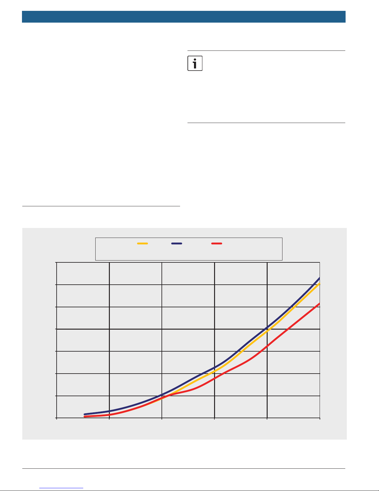
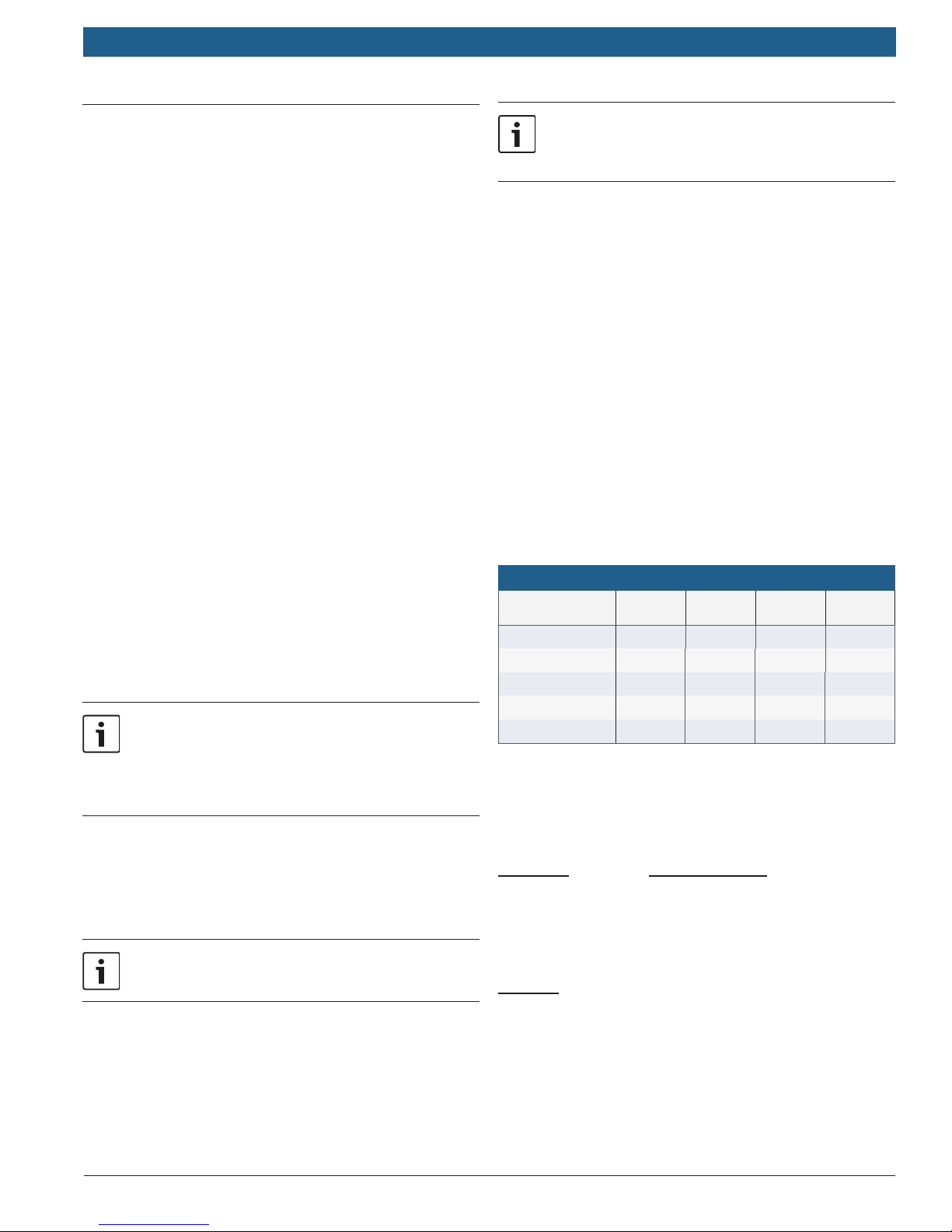
f Size the pump according to the pressure drop curve of
your Therm model (fig. 1 below) and the loop pressure
drop tables.
f Maximum flow allowed for tank loading through the
pump loop is 5 GPM.
f Maximum flow recommended for direct DHW
recirculation is 3 GPM.
f Maximum flow allowed for mini-tank DHW recirculation
is 2 GPM.
applications:
Run the system for 30 minutes to remove debris
from the plumbing. Then remove the unit‘s inlet
water lter to decrease pressure drop through
the system. If the inlet water lter, when removed, contains debris, it is recommended to install
a 40 mesh Y-strainer (installer supplied) on the
cold water inlet.
5.1 Pressure drop curves
70
60
50
40
30
Pressure (Feet of Head)
20
C 950 ES
C 1050 ES
C 1210 series
830 ES,
940 ES / ESO
10
0
F
igure 1 Pressure drop curves
Bosch Thermotechnology Corp.
0.50.40.30.20.10.0
Flow (GPM)
Data subject to change
Page 8
|
8
THERM/GREENTHERM Tankless Water Heaters
Applications Manual
5.2 Domestic hot water circulation
5.2.1 Ariston mini-tank DHW recirculation
Reference drawing 9.2.3 on page 20.
If recirculating through an Ariston mini-tank only, use the
smallest pump that will overcome the pressure of the loop.
Recommended ow rate within the range of 1 to 2 GPM.
This method of recirculation maintains warranty.
f The tank and the Therm should be set at roughly the
same temperature.
f An aquastat is required to control the recirculation
pump operation. An aquastat temperature setting of
110° F with a 10° F differential is recommended.
f The recirculation flow must be <2 gpm. Higher flows
will waste energy and can erode the Ariston anode,
requiring frequent anode replacement to maintain its
warranty.
f To minimize energy costs:
1. Insulate all pipes in the recirculation loop.
2. Install a timer or sensor system that will shut the
pump off when hot water will not be used.
f Recirculation loops over 200 feet in total length will
require an electric tank with a larger heating capacity
than the Ariston 8 gallon model.
5.2.2 Direct DHW recirculation
Reference drawing 9.2.4 on page 21.
If the Bosch tankless water heater provides the
heat source for recirculated water , the heat
exchanger warranty is decreased. Please refer
to the installation manual for detailed warranty
period information.
f Direct recirculation flow through the tankless water
heater must be above 1.7 gpm for best performance.
Flow can be verified in the diagnostic menu, mode
P4-3d. Refer to the Diagnostic Menu section of your
Therm installation manual for details.
System conditions vary and each pump must be
sized by a professional to insure performance.
Use only bronze or stainless steel pumps. Do not
use pumps of iron construction as they will oxidize and clog the inlet lter on the appliance.
f When properly installed in a direct recirculation
application the Therm will regulate water temperature
in a recirculation loop within a 20° F range. A
thermostatic mixing valve is required after the water
heater if no other temperature control is used.
f Closer temperature control can also be accomplished
with a recirculation pump aquastat. The Therm
temperature setting must always be at least 14° F
higher than the aquastat cut-out setting.
EXAMPLE:
— Therm temperature setting: 122° F
— Aquastat cut-out temperature setting: 108° F
— To minimize energy costs:
1. Insulate all pipes in the recirculation loop.
2. Install a timer or sensor system that will shut
the pump off when hot water will not be used.
Recirculation Loop Pressure Drop at 2GPM (Feet of Head)
10 ft Pipe 90 Elbow 45 Elbow
½" Type L Copper
¾" Type L Copper
¾" Pex
" Pex
½" Pex
Source: 2009 International Plumbing Code
0.85 0.09 0.05 0.18
0.15 0.03 0.01 0.05
0.25 0.02 N/A 0.03
0.53 0.04 N/A 0.06
1.3 0.12 N/A 0.18
Tee
Branch
EXAMPLE:
Sizing a pump for a 2gpm direct DHW recirc system with a
THERM 940ES and have 150 ft total loop length.
Head Loss Loop Component
9.00 ft 940ES (See Fig.1, page 7)
1.20 ft 80 ft of ¾" copper
5.90 ft 70 ft of ½" copper return
0.24 ft 8 x ¾" 90 elbows
0.10 ft 2 x ¾" Tees (branch)
0.72 ft 8 x ½" 90 elbows
+ 0.18 ft 1 x ½" Tee (branch)
Refer to pump manufacturers ow vs pressure
speci cations to select a pump that can provide ow
between 1.7 gpm and 3 gpm while overcoming the
pressure loss through the Therm and the recirculation
loop. Refer to gure 1 and table... to determine pressure
loss.
17.34 ft Minimum Pump Head at 2.0 gpm
Once the loop head loss has been calculated, use the
pump manufacturer’s performance curves to select the
proper potable water circulator at the required ow rate.
Bosch Thermotechnology Corp.Data subject to change
Page 9

Applications Manual THERM/GREENTHERM Tankless Water Heaters | 9
5.3 Tank loading
Refer to drawings 13.2 and 13.3 on pages 32 and 33.
Tank loading pairs tankless water heaters with storage
tanks to maximize peak ow for high demand applications.
A tank load system, because of the added storage, can
provide a high peak ow with fewer tankless units and
lower installed cost.
These guidelines should be followed to maximize system
output:
f Ensure flow through each water heater is between
3.5-5.0 gpm.
f Isolation valves or boiler drains should be installed to
facilitate descaling in applications with hard water.
f For best performance, plumb the system or configure
the tank to draw cold supply water into the water
heater during hot water use.
f Maintain a 20 degree temperature difference between
tankless set-point and desired tank temperature.
f Do not use a cascading kit in a tank loading
application.
f When multiple tankless water heaters are used, the
total equivalent length of piping to each unit should
be kept roughly equal. A reverse return piping scheme
is recommended to equalize flow through each water
heater.
f For tank temperature settings above 120° F, the Therm
C 1210 ESC is recommended. Other high capacity
Therms including the 830 ES, 940 ES/ESO, C 950 ES
and C 1050 ES can be used, but a high temperature
kit (part 7736500074) is required for each. In these
applications a thermostatic mixing valve is required.
Pressure drop vs. ow*
# of
Units
1 40 feet of head @ 4gpm 32 feet of head @ 4gpm
2 40 feet of head @ 8gpm 32 feet of head @ 8gpm
3 40 feet of head @ 12gpm 32 feet of head @ 12gpm
4 40 feet of head @ 16gpm 32 feet of head @ 16gpm
5 40 feet of head @ 20gpm 32 feet of head @ 20gpm
6 40 feet of head @ 24gpm 32 feet of head @ 24gpm
7 40 feet of head @ 28gpm 32 feet of head @ 28gpm
8 40 feet of head @ 32gpm 32 feet of head @ 32gpm
9 40 feet of head @ 36gpm 32 feet of head @ 36gpm
10 40 feet of head @ 40gpm 32 feet of head @ 40gpm
11 40 feet of head @ 44gpm 32 feet of head @ 44gpm
12 40 feet of head @ 48gpm 32 feet of head @ 48gpm
13 40 feet of head @ 52gpm 32 feet of head @ 52gpm
14 40 feet of head @ 56gpm 32 feet of head @ 56gpm
15 40 feet of head @ 60gpm 32 feet of head @ 60gpm
16 40 feet of head @ 64gpm 32 feet of head @ 64gpm
17 40 feet of head @ 68gpm 32 feet of head @ 68gpm
18 40 feet of head @ 72gpm 32 feet of head @ 72gpm
19 40 feet of head @ 76gpm 32 feet of head @ 76gpm
20 40 feet of head @ 80gpm 32 feet of head @ 80gpm
21 40 feet of head @ 84gpm 32 feet of head @ 84gpm
22 40 feet of head @ 88gpm 32 feet of head @ 88gpm
23 40 feet of head @ 92gpm 32 feet of head @ 92gpm
24 40 feet of head @ 96gpm 32 feet of head @ 96gpm
C 1210 ES / ESC,
C 1050 ES, C 950 ES
940 ES, 940 ESO, 830 ES
EXAMPLE:
Sizing a pump for a 4GPM tank loading DHW system with a
1050ES and a 20 ft total loop length.
Tank Loading Loop Pressure Drop at 4GPM (Feet of Head)
10 ft
Pipe
¾" Type L Copper
1" Type L Copper 0.14 0.04 0.02 0.07
1.25" Type L Copper 0.06 0.02 0.01 0.04
1.5" Type L Copper 0.03 0.01 <0.01 0.02
2" Type L Copper 0.01 <0.01 <0.01 0.01
Source: 2009 International Plumbing Code
* Calculations based on 120°F Set-point temperature, 107°F shower temperature, 2.5 GPM showerhead ow rate, 1.5 GPM sink ow rate,
adequate water pressure and gas supply. Variation from these parameters may alter performance. GPM shown is the hot water ow rate
at
120°F Set-point temperature.
Bosch Thermotechnology Corp.
0.48 0.1 0.03 0.15
90
Elbow
45
Elbow
Tee
Branch
Head Loss Loop Component
39.00 ft 1050es (See Fig.1, page 7)
1.00 ft 20 ft of ¾ copper
0.80 ft 8 x ¾” 90 elbows
+ 0.30 ft 2 x ¾” Tees (branch)
41.10 ft Minimum Pump Head at 4.0 gpm
Once the loop head loss has been calculated, use the
pump manufacturer’s performance curves to select the
proper potable water circulator at the required ow rate.
Data subject to change
Page 10
O
C
UT
CO
S
S
OKMO
O
S
G
SC
C
|
10
THERM/GREENTHERM Tankless Water Heaters
6 Water Heater Sizing &
Speci cations
This section describes the water heaters available from
Bosch Thermotechnology Corp. and provides a general
overview to the speci cations of each particular model.
More detailed information is contained in the installation
manuals. Download manuals at www.bosch-climate.us.
6.1 Sizing tankless water heaters
Rule of thumb sizing
The tables below provide a general rule of thumb when
sizing for most residential applications. For commercial
applications or for a more detailed sizing method, use the
Sizing by Chart instructions below in conjunction with the
charts on the next page.
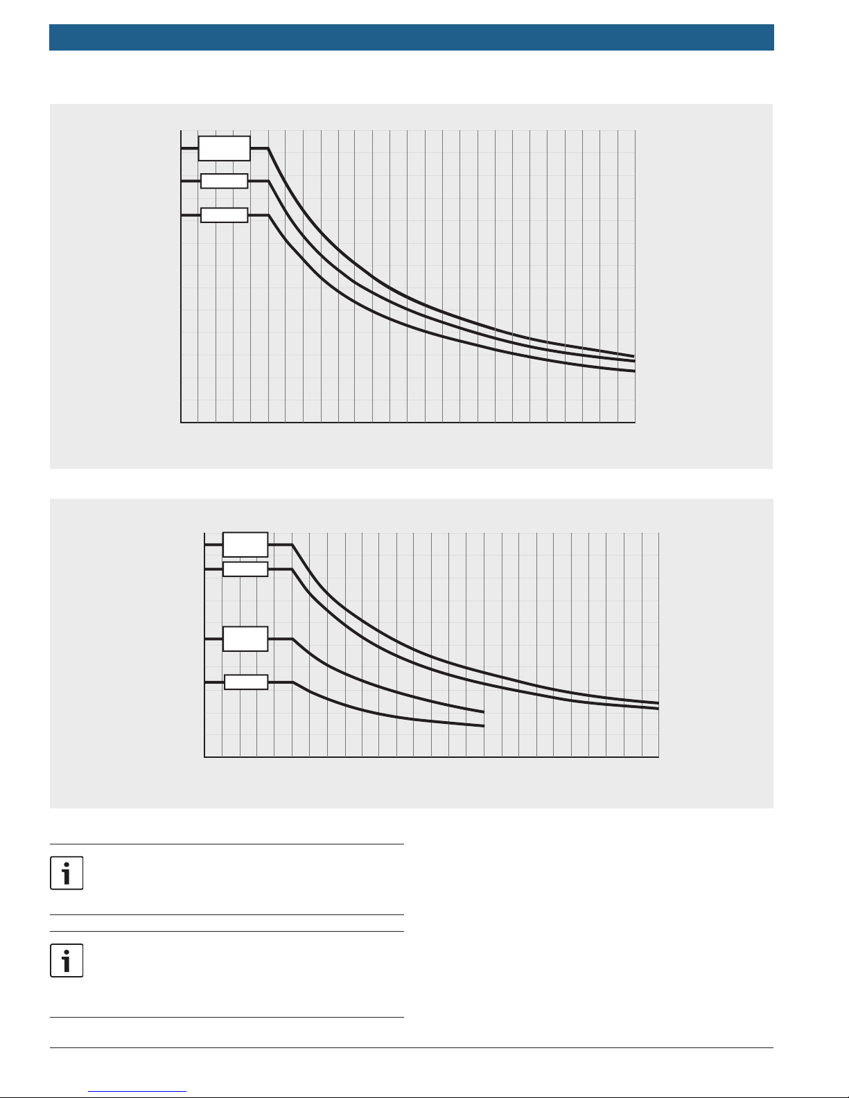
Sizing by Chart
f Measure the flow rates at each fixture that will be
used simultaneously and add them together. If only
one application will be used at a time measure each
fixture and use the maximum flow rate observed.
Applications Manual
WA
R
OR
NV
CA
A
MT
ID
UT
AZ
ND
MN
D
SD
WY
CO
NM
IA
NE
K
KS
MO
OK
AR
TX
LA
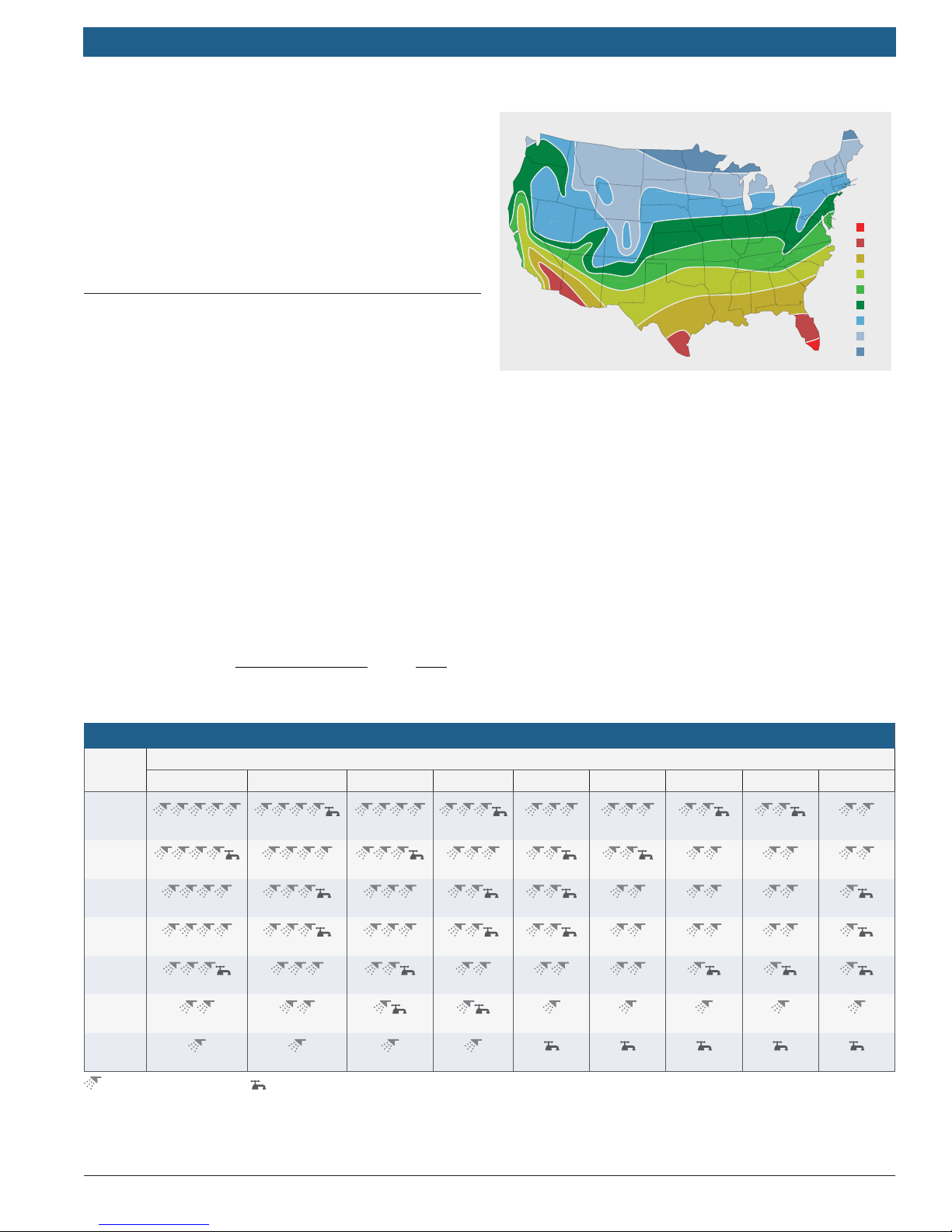
Figure 2 Average ground water temperatures
WI
MI
OH
H
IN
IL
KY
TN
GA
M
MS
AL
VT
NY
PA
VA
WV
N
NC
SC
A
FL
f Using a thermometer, measure the incoming water
temperature. For reference, see average ground water
temperature map. Subtract this temperature from
the desired hot water temperature to get the degree
rise. If the desired hot water temperature is 120F and
incoming temperature is 55F, the desired degree rise
is 65F.
ME
NH
RI
MA
CT
NJ
˚F
DE
77˚
MD
72˚
67˚
62˚
57˚
52˚
47˚
42˚
37˚
f Using a known volume container, record several fill
times. Perform the calculation below to determine the
flow rate (a one gallon fill time of 30 seconds is 2.0
gallons per minute (GPM):
Flow rate (GPM) =
Volume (gallons)
Fill time (sec)
Hot water ow rate at 120°F Set Point temperature
Model
C 1210
ES /
ESC
C 1050
ES
C 950
ES
940 ES
/ ESO
830 ES
520 HN
/ PN
77° 72° 67° 62° 57° 52° 47° 42° 37°
9.8 8.8 8.0 7.3 6.7 6.2 5.8 5.4 5.1
8.5 7.6 6.9 6.3 5.8 5.4 5.0 4.7 4.4
7.7 6.9 6.2 5.7 5.2 4.9 4.5 4.2 4.0
7.7 6.9 6.2 5.7 5.2 4.9 4.5 4.2 4.0
6.7 6.0 5.4 5.0 4.6 4.2 4.0 3.7 3.5
4.3 3.8 3.5 3.2 2.9 2.7 2.5 2.3 2.2
sec
x
60
min
EXAMPLE:
f Required flow rate of 2.0 GPM at a 65F rise.
f Refer to the graphs on page 10.
f Since the demand is above the 330 PN capacity, this
application would require a 520 HN/PN gas tankless
water heater.
Inlet temperature (°F)
330 PN
2.7 2.4 2.2 2.0
Simultaneous Showers Sink Faucet
1.9 1.7 1.6 1.5 1.4
Bosch Thermotechnology Corp.Data subject to change
Page 11
Applications Manual THERM/GREENTHERM Tankless Water Heaters | 11
13
C 1210 ES/
12
C 1210 ESC
11
C 1050 ES
10
C 950 ES
9
8
Flow
7
Rate
(GPM)
6
5
4
3
2
1
0
10 20 30 40 50 60 70 80 90
Temperature rise (°F)
100 110 120 130 140
Figure 3 Flow rate vs. temperature rise - condensing models
11
10
Flow
Rate
(GPM)
940 ES/
940 ESO
9
830 ES
8
7
6
520 HN/
520 PN
5
4
330 PN
3
2
1
0
10 20 30 40 50 60 70 80 90
Figure 4 Flow rate vs. temperature rise - non-condensing models
Flows above 10 GPM require installation of a
mixing valve to help mitigate pressure drop in the
water heater and plumbing system
100 110 120 130 140
Temperature rise (°F)
Temperature rises above 110 °F or more,
or output temperatures above 140 °F require
either a commercial unit or optional accessories
such as a high temperature kit.
Bosch Thermotechnology Corp.
Data subject to change
Page 12
|
12
THERM/GREENTHERM Tankless Water Heaters
Applications Manual
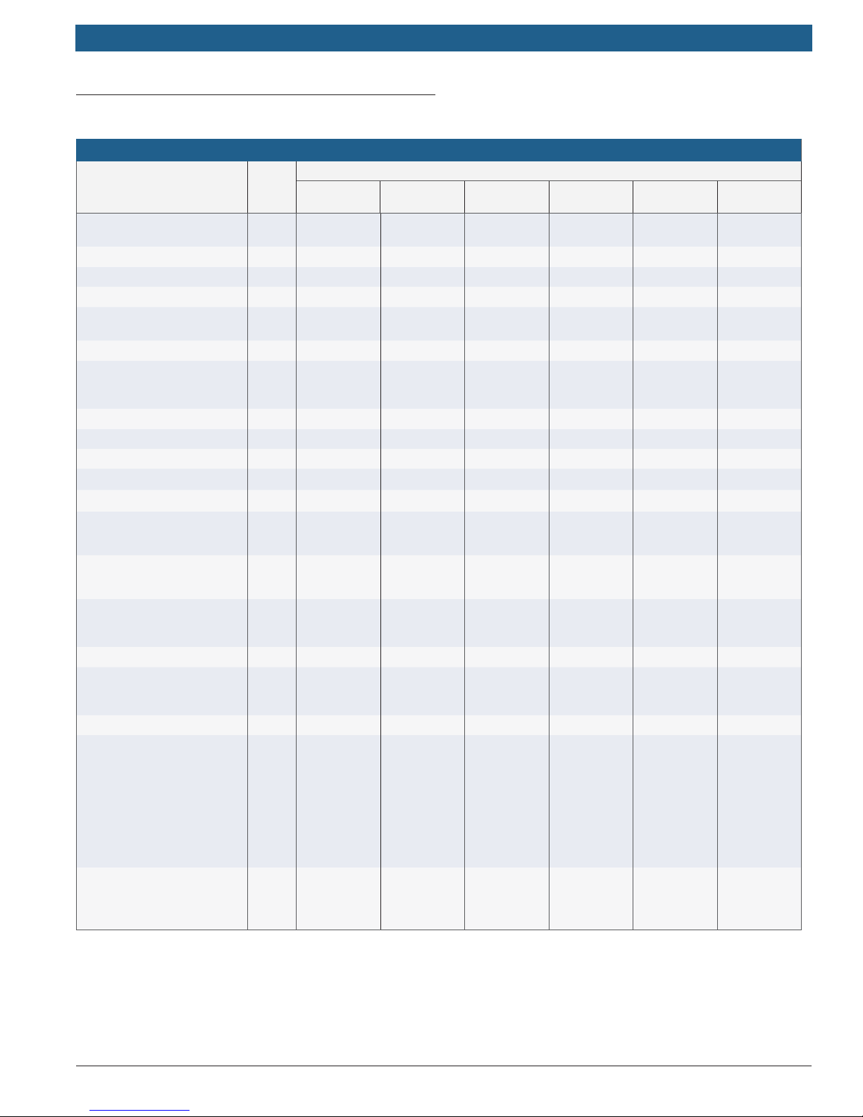
6.2 Tankless Water Heater Speci cations
Technical Speci cations
Models
Unit
Gas input BTU/hr
Minimum ow to activate GPM 0.5 0.5 0.5 0.5 0.5 0.5
Maximum ow rate at 35° rise GPM 12.1 10.5 9.2 9.4 9.4 8.3
Maximum ow rate at 90° rise GPM 4.6 3.9 3.6 3.6 3.6 3.6
Thermal ef ciency %
Energy factor N/A .94 .93 .83 .83 .83
Dimensions Inches
Weight LBS 88 74 74 67 67 67
Modulating gas valve Electronic Electronic Electronic Electronic Electronic Electronic
Ignition Electronic Electronic Electronic Electronic Electronic Electronic
Gas connection Inches
Water connections Inches
Inches
NG gas pressure
W.C.
Inches
LP gas pressure
W.C.
Water pressure- static PSI
Electrical supply VAC 120 120 120 120 120 120
Venting options
Venting diameter Inches 3 or 4 3 or 4 3 or 4 3 or 4 N/A 3 or 4
Vent material
Temperature range °F
C 1210 ES /
C 1210 ESC
Max: 225,000
Min: 25,000
NG: 94
LP: 94
H: 30½
W: 17
D: 11¼
C 1050 ES C 950 ES 940 ES 940 ESO 830 ES
Max: 199,000
Min: 19,900
NG: 94
LP: 94
H: 30½
W: 17
D: 11¼
Max: 175,000
Min: 19,900
NG: 93
LP: 93
H: 30½
W: 17
D: 11¼
Max: 199,000
Min: 19,900
NG: 82
LP: 82
H: 30½
W: 17
D: 11¼
Max: 199,000
Min: 19,900
NG: 82
LP: 82
H: 30½
W: 17
D: 11¼
¾ Male NPT ¾ Male NPT ¾ Male NPT ¾ Male NPT ¾ Male NPT ¾ Male NPT
¾ Male NPT ¾ Male NPT ¾ Male NPT ¾ Male NPT ¾ Male NPT ¾ Male NPT
of
of
Min: 3.5
Max: 10.5
Min: 8.0
Max: 13.0
Min: 30
Min (well): 40
Max: 145
direct vent,
room-sealed,
combustion
PP common
vent, PP twin
pipe, PVC,
CPVC,
or ABS
(Schedule 40)
100-180°F
(ESC)
100-140°F
(ES)
Min: 3.5
Max: 10.5
Min: 8.0
Max: 13.0
Min: 30
Min (well): 40
Max: 150
direct vent,
room-sealed,
combustion
PP common
vent, PP
up and out
concentric
vent, PP twin
pipe, PVC,
CPVC,
or ABS
(Schedule 40)
100-140°F
100-184°F
(requires HT
kit)
Min: 3.5
Max: 10.5
Min: 8.0
Max: 13.0
Min: 30
Min (well): 40
Max: 150
direct vent,
room-sealed,
combustion
PP common
vent, PP
up and out
concentric
vent, PP twin
pipe, PVC,
CPVC,
or ABS
(Schedule 40)
100-140°F
100-184°F
(requires HT
kit)
Min: 3.5
Max: 10.5
Min: 8.0
Max: 13.0
Min: 30
Min (well): 40
Max: 150
direct vent,
room-sealed,
combustion
Stainless
steel
(AL29-4C)
100-140°F
100-184°F
(requires HT
kit)
Min: 3.5
Max: 10.5
Min: 8.0
Max: 13.0
Min: 30
Min (well): 40
Max: 150
outdoor
installation
only
Outdoor vent
cap supplied
100-140°F
100-184°F
(requires HT
kit)
Max: 175,000
Min: 19,900
NG: 82
LP: 82
H: 30½
W: 17
D: 11¼
Min: 3.5
Max: 10.5
Min: 8.0
Max: 13.0
Min: 30
Min (well): 40
Max: 150
direct vent,
room-sealed,
combustion
Stainless
steel
(AL29-4C)
100-140°F
100-184°F
(requires HT
kit)
Bosch Thermotechnology Corp.Data subject to change
Page 13
Applications Manual THERM/GREENTHERM Tankless Water Heaters | 13
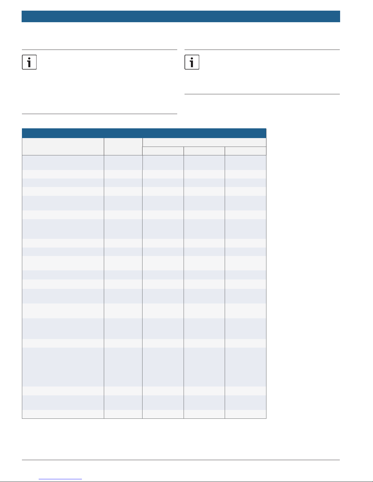
- C 1210 ES (residential model) has a maximum
set-point temperature of 140°F.
- C 1210 ESC (commercial model) has a maximum
set-point temperature of 180°F.
- To achieve temperatures up to 184°F with C
The following models are designed to be installed
indoors but may be installed outdoors with the
Outdoor Kit: 830 ES, 940 ES, C 950 ES, C 1050 ES,
C 1210 ES / ESC. Please refer to the installation
manuals for details.
1050 ES, C950 ES, 940 ES, 940 ESO, and 830 ES,
the optional High Temperature kit #7736500074
is required.
Technical speci cations
Unit
Gas input BTU/hr
Minimum ow to activate GPM 0.5 0.5 0.5
Maximum ow rate at 35° rise GPM 5.2 5.2 3.3
Maximum ow rate at 90° rise GPM 2.0 2.0 1.3
Thermal ef ciency %
Energy factor N/A N/A N/A
Dimensions Inches
Weight LBS 35 35 36
Modulating gas valve Mechanical Mechanical Mechanical
Ignition
Gas connection Inches
Water connections Inches
NG gas pressure Inches of W.C.
LP gas pressure Inches of W.C.
Water pressure- static PSI
Electrical supply VAC N/A N/A N/A
Venting options
Venting diameter Inches 5 5 4
Vent material
Temperature range °F High to low High to low High to low
520 HN 520 PN 330 PN
Max: 117,000
Min: 30,735
NG: 80
LP: 80
H: 25.79
W: 17.11
D: 8.66
Hydrogenerated
Max: 117,000
Min: 30,735
NG: 78
LP: 78
H: 25.79
W: 18.11
D: 8.66
Standing
pilot
Max: 74,900
Min: 30,735
NG: 78
LP: 78
H: 22.83
W: 12.20
D: 8.66
Standing
pilot
¾ Male NPT ¾ Male NPT ½ Male NPT
½ Male NPT ½ Male NPT ½ Male NPT
Min: 5.7
Max: 14.0
Min: 10.5
Max: 14.0
Min: 30
Min (well): 40
Max: 150
Vertical
natural draft,
Horizontal
termination
only with AQ4
vent kit
Type B-vent
recommended
Min: 5.7
Max: 14.0
Min: 10.5
Max: 14.0
Min: 30
Min (well): 40
Max: 150
Vertical
natural draft,
Horizontal
termination
only with AQ4
vent kit
Type B-vent
recommended
Min: 5.7
Max: 14.0
Min: 10.5
Max: 14.0
Min: 30
Min (well): 40
Max: 150
Vertical
natural draft,
Horizontal
termination
not allowed
Type B-vent
recommended
Bosch Thermotechnology Corp.
Data subject to change
Page 14

|
14
THERM/GREENTHERM Tankless Water Heaters
7 Water Quality
Water quality can have an impact on appliance
longevity and may void the manufacturer's warranty.
For water analysis data call your local water department,
or if on a well, have well water analyzed periodically. If
water quality exceeds one or more of the values
speci ed below, Bosch recommends installing a water
conditioner or softener. If the tankless water heater is
operating in applications where the outlet temperature
exceeds 140°F, a water softening system is strongly
recommended. The higher the set temperature is on the
appliance, the greater the risk for scale/mineral
deposits. Damage from scale/mineral deposits is not
covered under warranty. Refer to manufacturer’s limited
warranty.
Water quality limits
Description Unit Max. Levels
pH pH 6.5 - 8.5
TDS (total dissolved solids) mg/l or ppm 500
Total hardness mg/l or ppm 100 (6 grains)
Aluminum mg/l or ppm 2.0
Chlorides mg/l or ppm 250
Copper mg/l or ppm 1.0
Iron mg/l or ppm 0.3
Manganese mg/l or ppm 0.05
Zinc mg/l or ppm 5.0
Applications Manual
Bosch Thermotechnology Corp.Data subject to change
Page 15
Applications Manual THERM/GREENTHERM Tankless Water Heaters | 15
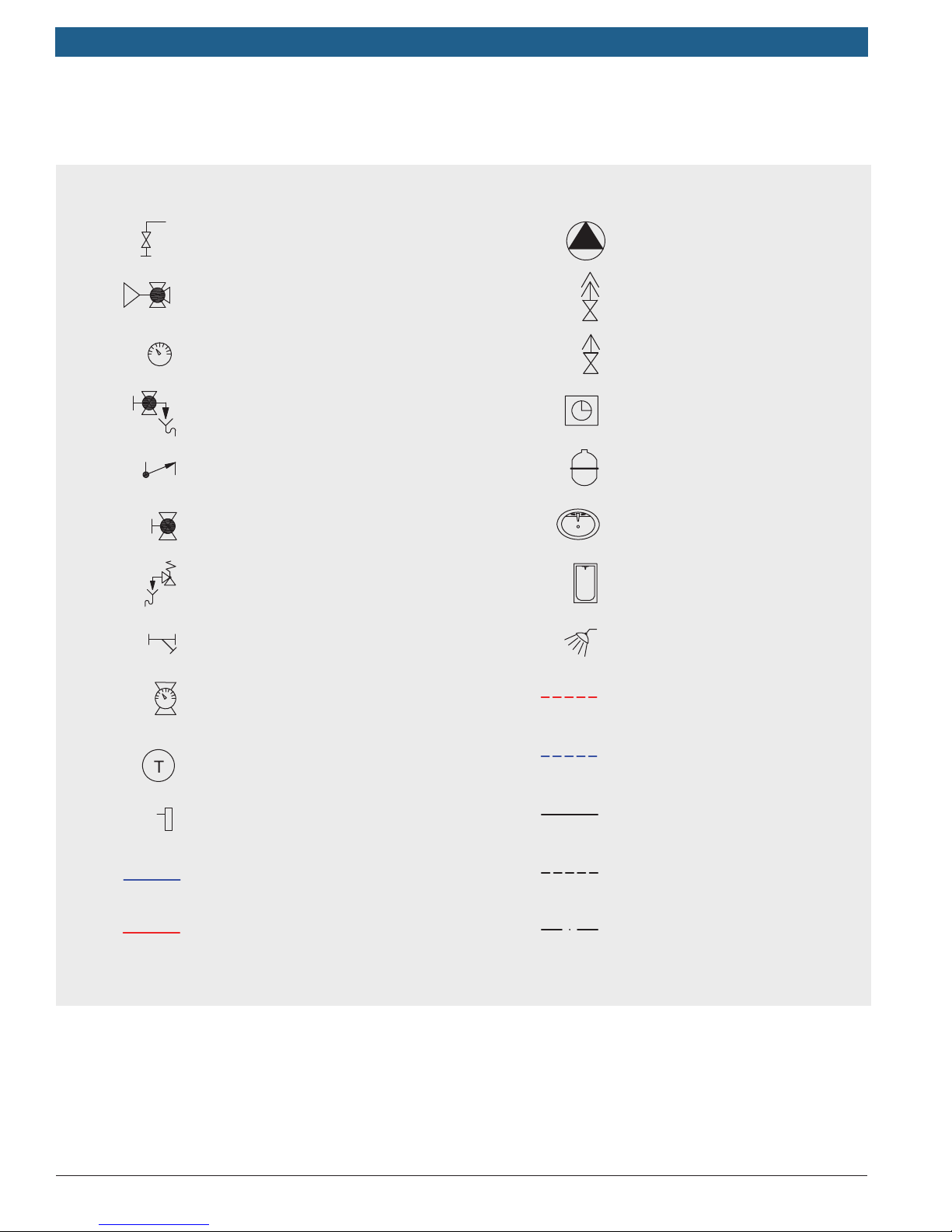
8 Applications Legend
Tank drain valve
Thermostatic 3-way valve
Gauge
Shutoff valve with drain
Check valve
Two way shutoff valve
Safety relief valve
Y-Strainer
Shutoff valve with
temperature gauge
Pump
Automatic air vent valve
Manual air vent valve
Timer
Expansion tank
Sink
Standard tub
Shower
Solar supply pipe
Temperature sensor
Aquastat
Cold water pipe
Hot water pipe
NOTICE: These drawings are conceptual in nature, not to scale and for reference only. Additional functional,
installation, and safety devices may be needed or required. All work pertaining to the installation shall be in full
compliance with all legal requirements, including national and local codes. Best installation practices should be
followed.
Bosch Thermotechnology Corp.
Solar return pipe
Line voltage connection
Sensor connection
Intelligent cascade kit
Data subject to change
Page 16

|
16
THERM/GREENTHERM Tankless Water Heaters
9 Domestic Water Heating
Applications
Potable water
Potable water is water that is suitable for drinking. Bosch
Thermotechnology Corp. appliances are approved to heat
potable water only. Heating any other liquid other than potable water will void the manufacturer’s warranty covering
the appliance.
Introduction
This chapter covers the various application techniques
Bosch Thermotechnology Corp. recommends. The
schematics are to be used by professional contractors
in designing a domestic water heating system. The
applications covered range from single appliance low
volume to multi-appliance central domestic recirculation.
Applications Manual
Bosch Thermotechnology Corp.Data subject to change
Page 17
Applications Manual THERM/GREENTHERM Tankless Water Heaters | 17
9.1 Low volume applications
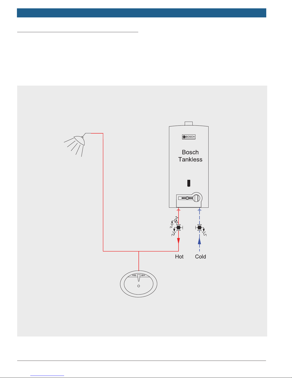
Low volume applications cover the small applications in
which a large water heater would be inef cient. Common
applications for these appliances include cottages, cabins,
and summer camps. The Bosch THERM 520HN, 520PN
and 330PN gas tankless water heaters offers compact
and lightweight design for easy installation in these
applications.
Applicable models: Bosch 330 PN, 520 PN, 520 HN.
Bosch Thermotechnology Corp.
Data subject to change
Page 18
|
18
THERM/GREENTHERM Tankless Water Heaters
9.2 Whole house applications
Whole house applications cover the typical home
applications up to a 2 to 4 bathroom house. See the sizing
guide (page 9) to determine the best Bosch water heater
model for your application. An enhanced design combining
an Ariston mini tank in line after the Bosch water heater
will reduce wait times and improve temperature stability.
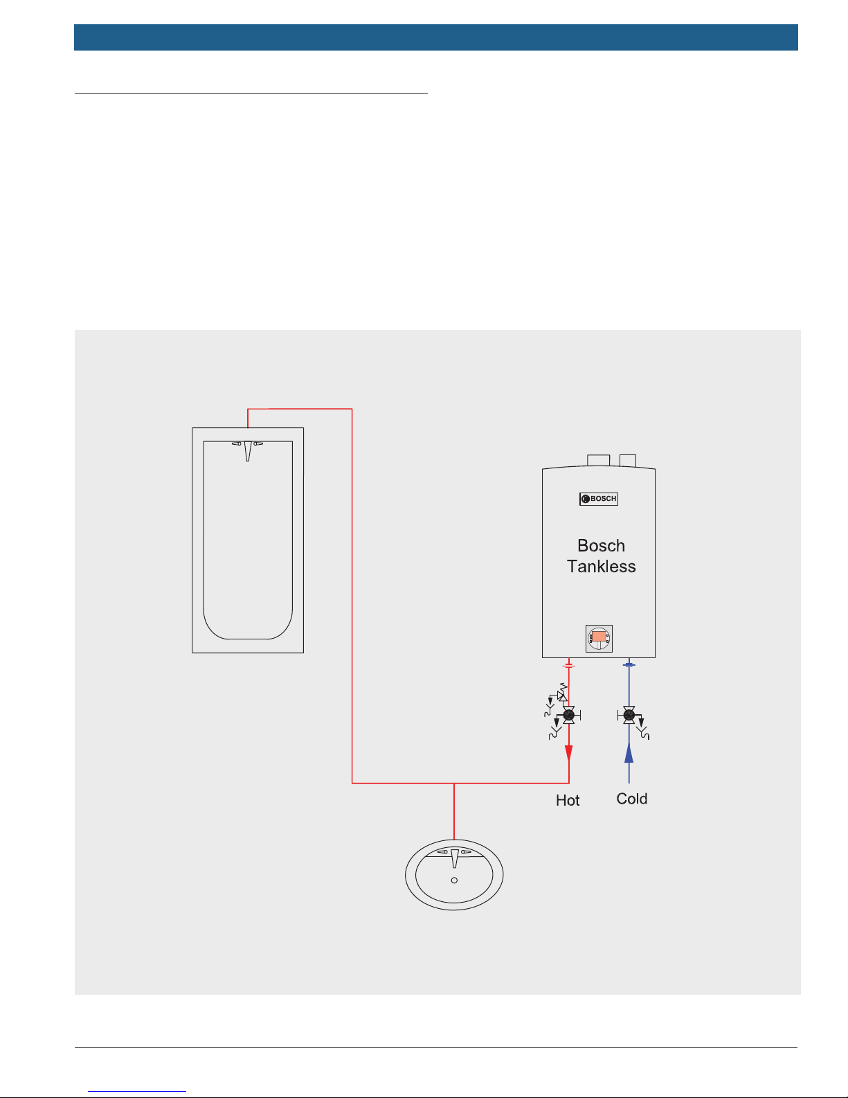
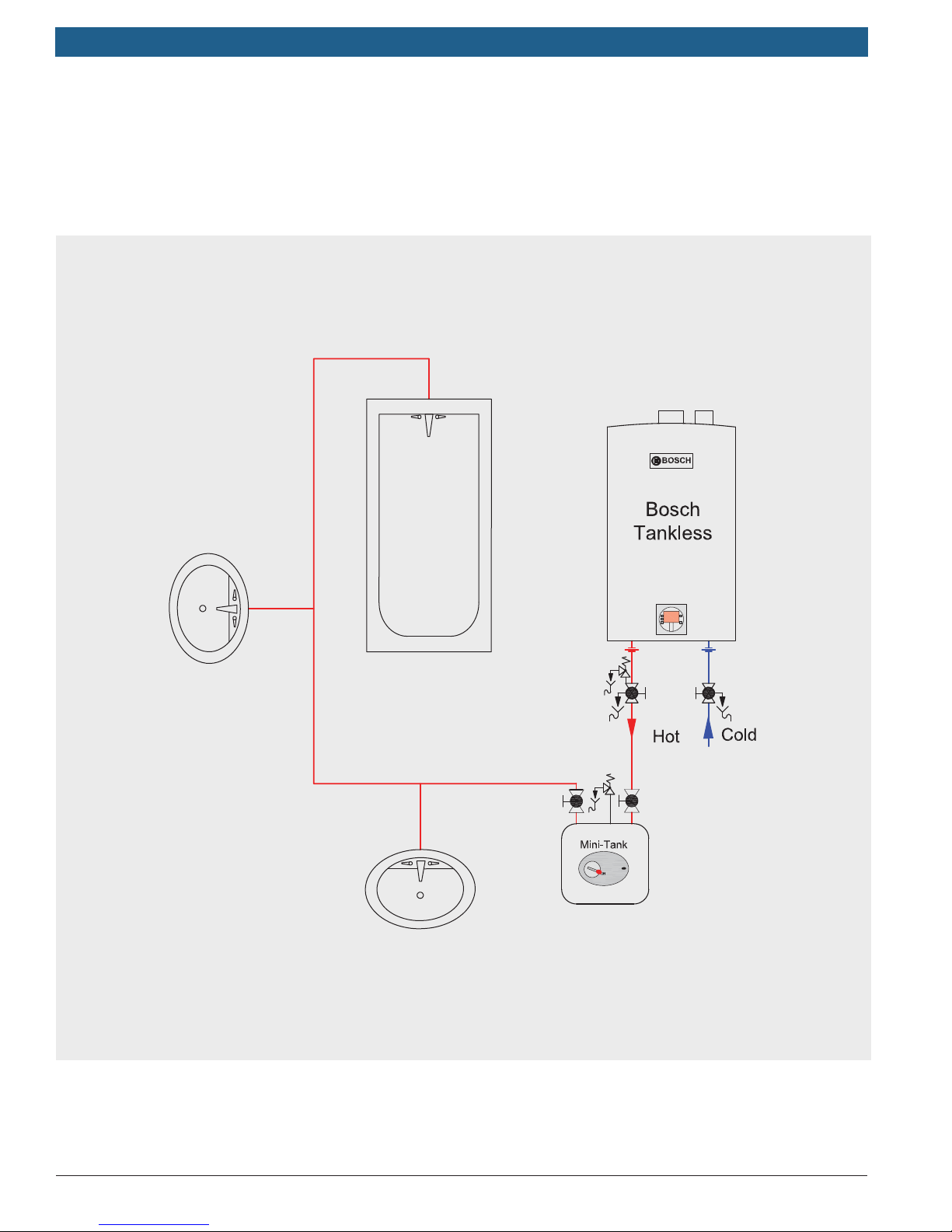
9.2.1 Bosch gas water heater
Below is an example of a basic Bosch gas tankless water
heater installation for the whole house.
Applications Manual
Applicable models: Bosch 830 ES, 940 ES, 940 ESO,
C 950 ES, C 1050 ES, C 1210 ES.
Bosch Thermotechnology Corp.Data subject to change
Page 19
Applications Manual THERM/GREENTHERM Tankless Water Heaters | 19
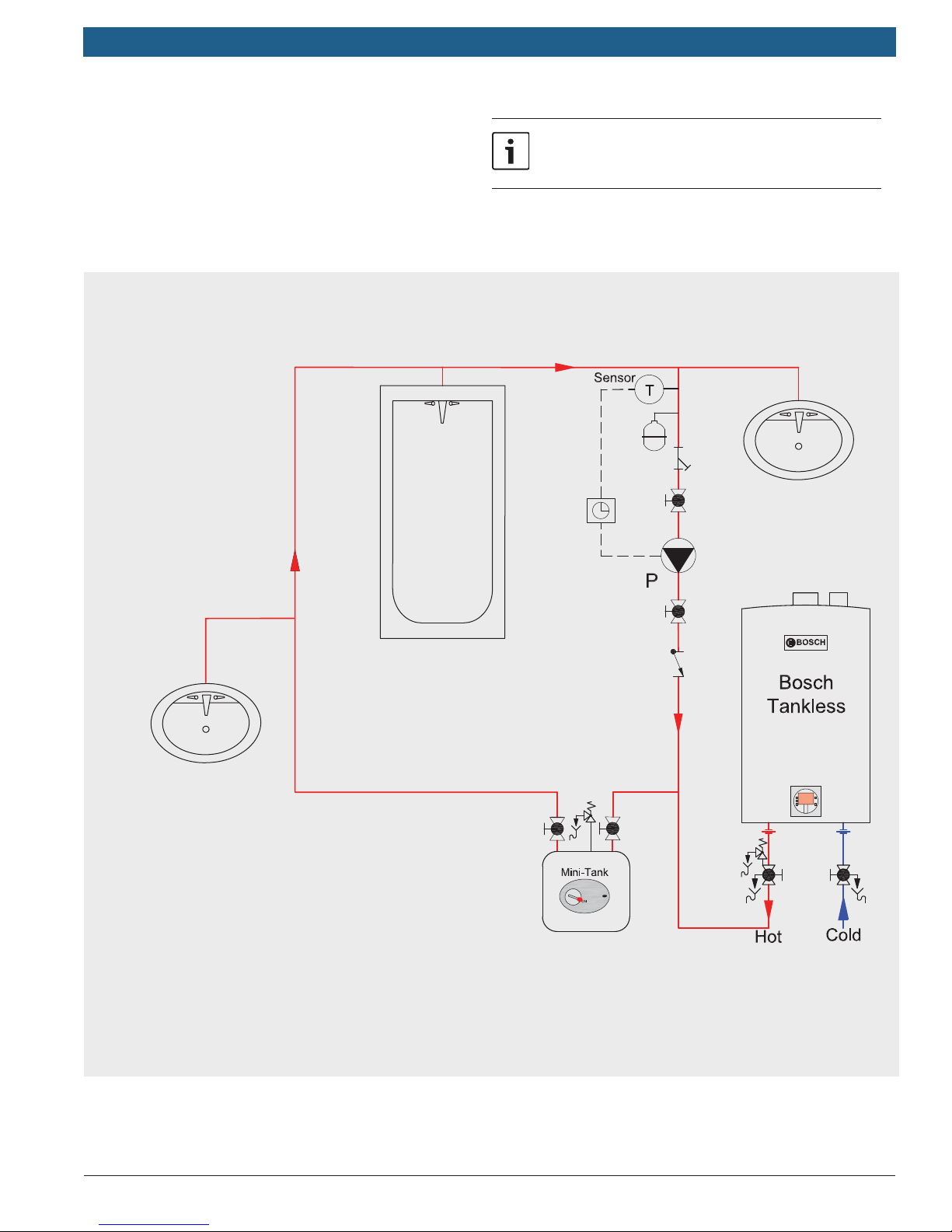
9.2.2 Bosch gas water heater with buffer tank
Below is an example of a Bosch gas tankless water heater
installation for the whole house. A Bosch Tronic 3000T
Applicable models: Bosch 520 PN, 520 HN, 830 ES,
940 ES, 940 ESO, C 950 ES, C 1050 ES, C 1210 ES.
mini tank (model ES8) is installed in line for reduced hot
water wait time and increased temperature stability.
Bosch Thermotechnology Corp.
Bosch
Data subject to change
Page 20
|
20
THERM/GREENTHERM Tankless Water Heaters
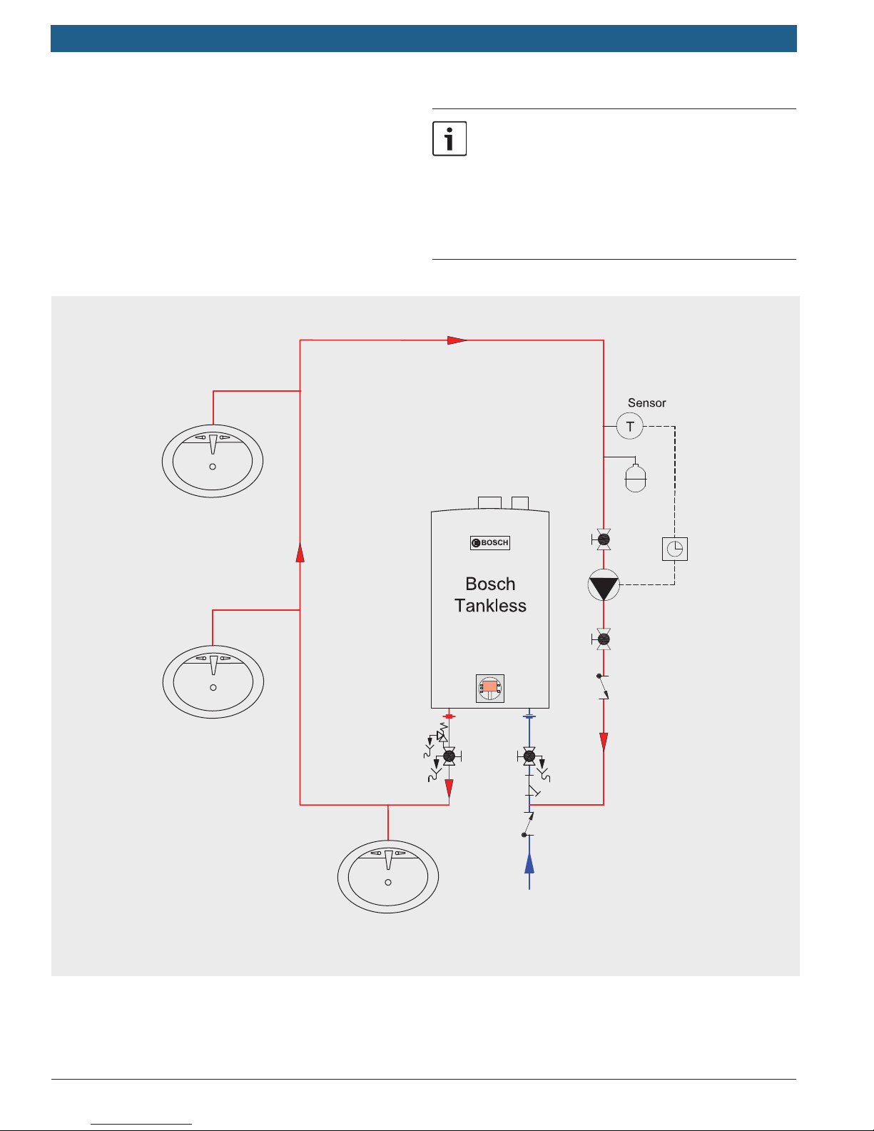
9.2.3 Bosch gas water heater with domestic
recirculation loop
The circulator should be controlled by an external aquastat and/or with a timer to run only during times of
expected hot water usage. Insulate piping in hot water
recirculation loop to limit heat loss.
Applications Manual
See Chapter 5.2 for recirculation pump
parameters
Applicable models: Bosch 520 PN, 520 HN, 830 ES,
940 ES, 940 ESO, C 950 ES, C 1050 ES, C 1210 ES,
Mini tank: Bosch Tronic 3000T ES8.
Bosch
Bosch Thermotechnology Corp.Data subject to change
Page 21
Applications Manual THERM/GREENTHERM Tankless Water Heaters | 21
9.2.4 Bosch gas water heater with direct recirculation
loop
Use a circulator, aquastat and/or timer, to keep a loop of
hot water constantly hot and ready to use. This limits wait
time for hot water delivery to the tap and excessive waste
of water. Insulate piping in hot water recirculation loop to
limit heat loss.
Applicable models: Bosch 830 ES, 940 ES, 940 ESO,
See Chapter 5.2 for recirculation pump
parameters
In this application the heat exchanger warranty is
reduced to 3 years. Please refer to section 8.2.3
for an application that maintains full warranty.
Please refer to the installation manual for detailed
warranty period information.
C 950 ES, C 1050 ES, C 1210 ES.
Bosch Thermotechnology Corp.
Data subject to change
Page 22

|
22
THERM/GREENTHERM Tankless Water Heaters
Applications Manual
10 High Volume Potable Water
Heating
Potable water
Potable water is water that is suitable for drinking. Bosch
Thermotechnology Corp. appliances are approved to heat
potable water only. Heating any other liquid other than
potable water will void the manfucturer’s warranty covering the appliance.
Introduction
This section lays out the options for high volume water
heating for large residential and light commercial applications including continuous ows.
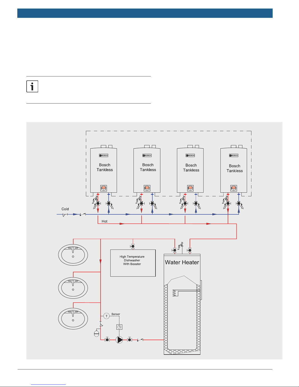
10.1 Cascading unit applications
A cascading application should be considered if the potential hot water demand exceeds the capacity of one gas
tankless water heater. The cascading set up supports variable ow inputs and is designed for large homes and commercial applications. Use of the Intelligent Cascading Kit ,
unlike other parallel applications, maintains the activation
ow rate of a single appliance.
Intelligent Cascading allows up to twenty four appliances
to be connected in parallel. One of the appliances will
serve as the controlling primary appliance and will attempt
to meet the hot water demand. If the hot water demand is
beyond the capacity of the primary appliance, a signal is
sent to one or more of the secondary appliances to ignite.
With the Intelligent Cascading, after each 100 hours of operation, the system will automatically rotate which heater
is serving as the primary.
An Intelligent Cascading Kit (part no. 7709003962) must
be purchased and installed for each secondary appliance
included in the installation.
Example:
A 7 unit cascade installation includes 1 primary appliance
and 6 secondary appliances. 6 intelligent cascading kits
must be purchased for this installation.
Bosch Thermotechnology Corp.Data subject to change
Page 23
Applications Manual THERM/GREENTHERM Tankless Water Heaters | 23
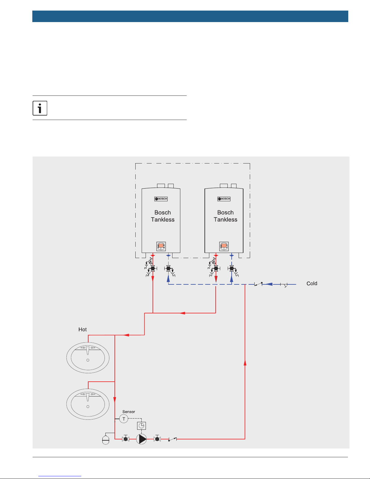
10.1.1 Intelligent cascading with domestic hot water
recirculation
For applications with 200ft of pipe or more.
Applicable models: Bosch 830 ES, 940 ES, 940 ESO,
C 950 ES, C 1050 ES, C 1210 ES
See Chapter 5.2 for recirculation pump
parameters
System parameters:
f The plumbing must be connected in the reverse return
method with a minimum number of elbows to aid in
balancing pressures between the appliances.
f Locate appliances close together for improved
performance.
— Maximum distance between appliances: 36”.
— Minimum distance between appliances: 1”
f Minimum pipe diameter: ¾” (2 appliances or less)
f Minimum pipe diameter: 1” (3 appliances or more).
f Minimum water pressure: 50 psi.
f Insulate pipes to prevent heat loss.
Bosch Thermotechnology Corp.
Data subject to change
Page 24
|
24
THERM/GREENTHERM Tankless Water Heaters
Applications Manual
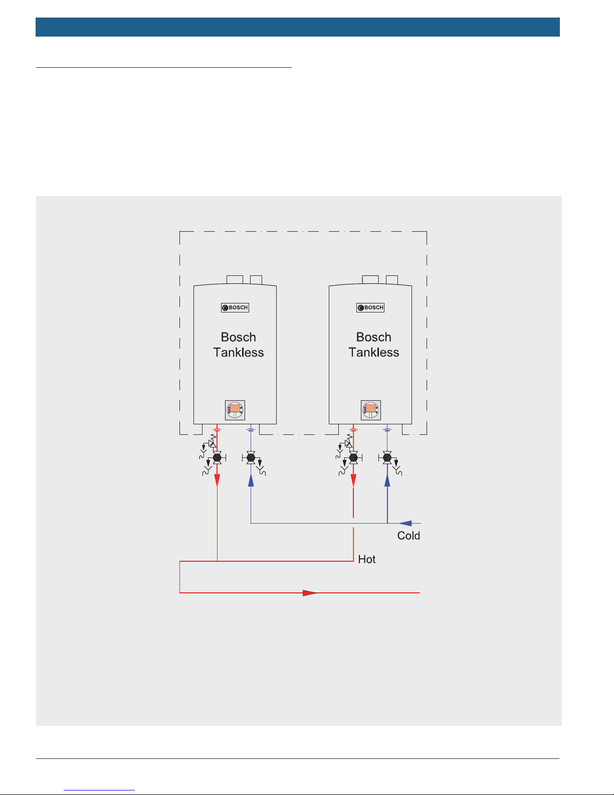
10.1.2 Intelligent cascading with domestic hot water
recirculation
For applications with 200ft of pipe or less.
Applicable models: Bosch 830 ES, 940 ES, 940 ESO,
C 950 ES, C 1050 ES, C 1210 ES
See Chapter 5.2 for recirculation pump parameters
System parameters:
f The plumbing must be connected in the reverse return
method with a minimum number of elbows to aid in
balancing pressures between the appliances.
f Locate appliances close together for improved
performance.
— Maximum distance between appliances: 36”.
— Minimum distance between appliances: 1”.
f Minimum pipe diameter: ¾” (2 appliances or less).
f Minimum water pressure: 50 psi.
f Insulate pipes to prevent heat loss.
Bosch Thermotechnology Corp.Data subject to change
Page 25
Applications Manual THERM/GREENTHERM Tankless Water Heaters | 25
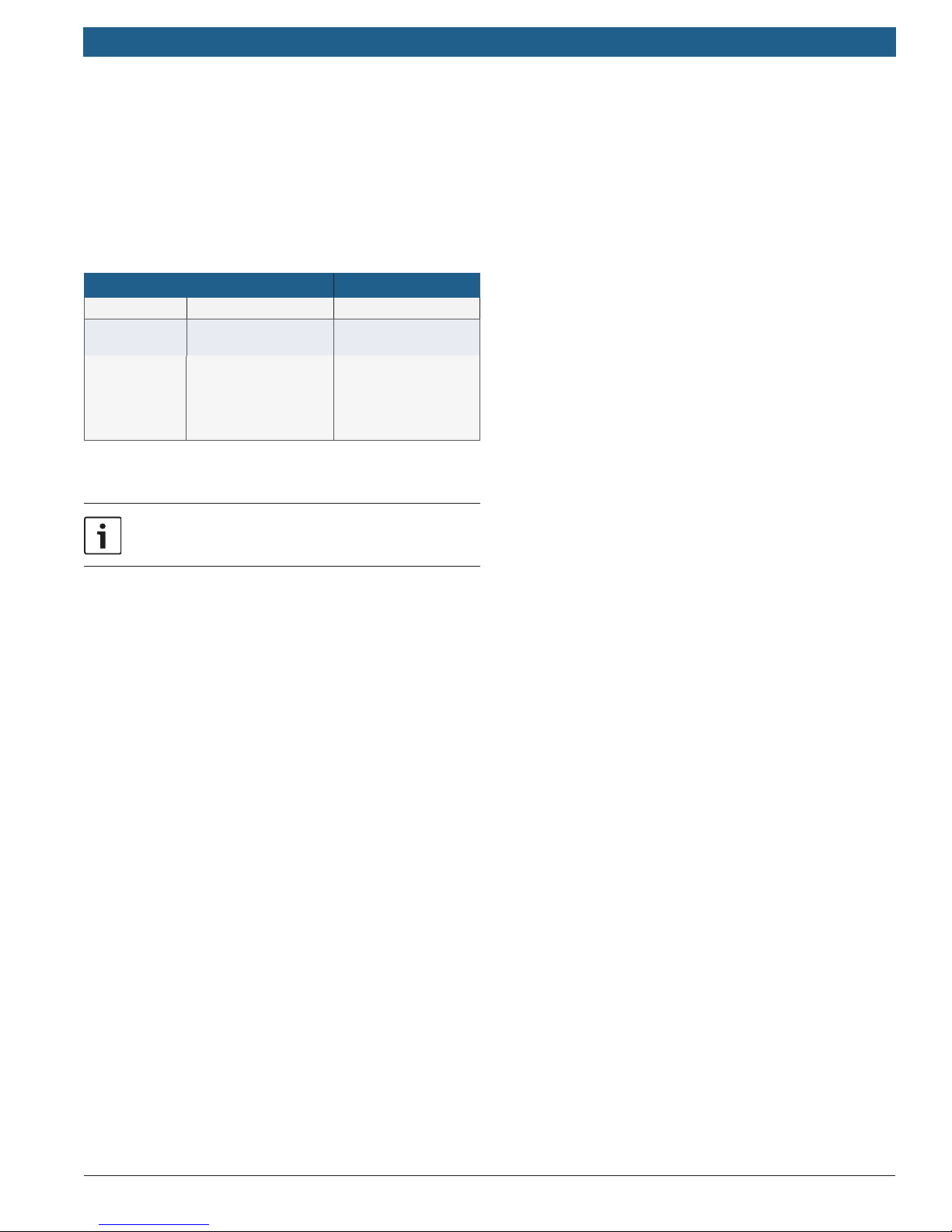
10.2 Parallel unit applications
Two Bosch water heaters plumbed in parallel will have
double the ow rate. However, the activation rate
increases with each unit added in parallel.
Example:
1 unit - 0.5 GPM activation rate
2 units - 1.0 GPM activation rate
3 units - 1.5 GPM activation rate
Optional Cascade Kit
Applicable models: Bosch 830 ES, 940 ES, 940 ESO,
C 950 ES, C 1050 ES, C 1210 ES.
NOTICE:
Use the Intelligent Cascading Kit only if low activation flows are
desired, and if it doesn't matter if full flow is not available
instantly. If the application demands higher flow rates more
quickly, do not install the Intelligent Cascading Kit.
If the Intelligent Cascading Kit is used the minimum activation
flow rate is equal to the activation flow rate of a single unit.
Bosch Thermotechnology Corp.
Data subject to change
Page 26
|
26
THERM/GREENTHERM Tankless Water Heaters
11 Residential Solar Applications
Introduction
This section gives a general overview of tank loading and
in line booster applications for domestic hot water in
conjuction with solar water heating. For additional system
details, consult the Bosch Solar Technical Guide.
Aquastat / water heater setpoints
Model Aquastat setpoint Water heater setpoint
C 1210 ESC 140°F
830 ES,
940 ES/ESO,
C 950 ES,
C 1050 ES,
C 1210 ES
* If local codes require higher setpoint or to increase the recovery
capacity of the water heater, contact Bosch Thermotechnology.
126°F* 140°F
14°F above Aquastat
setpoint
Applications Manual
See Chapter 5.2 for recirculation pump parameters
Bosch Thermotechnology Corp.Data subject to change
Page 27
Applications Manual THERM/GREENTHERM Tankless Water Heaters | 27
11.1 Booster applications
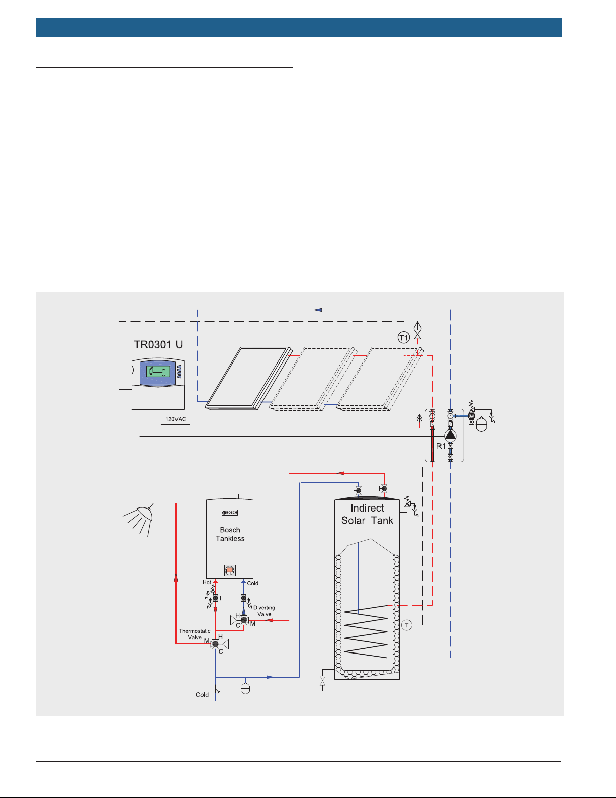
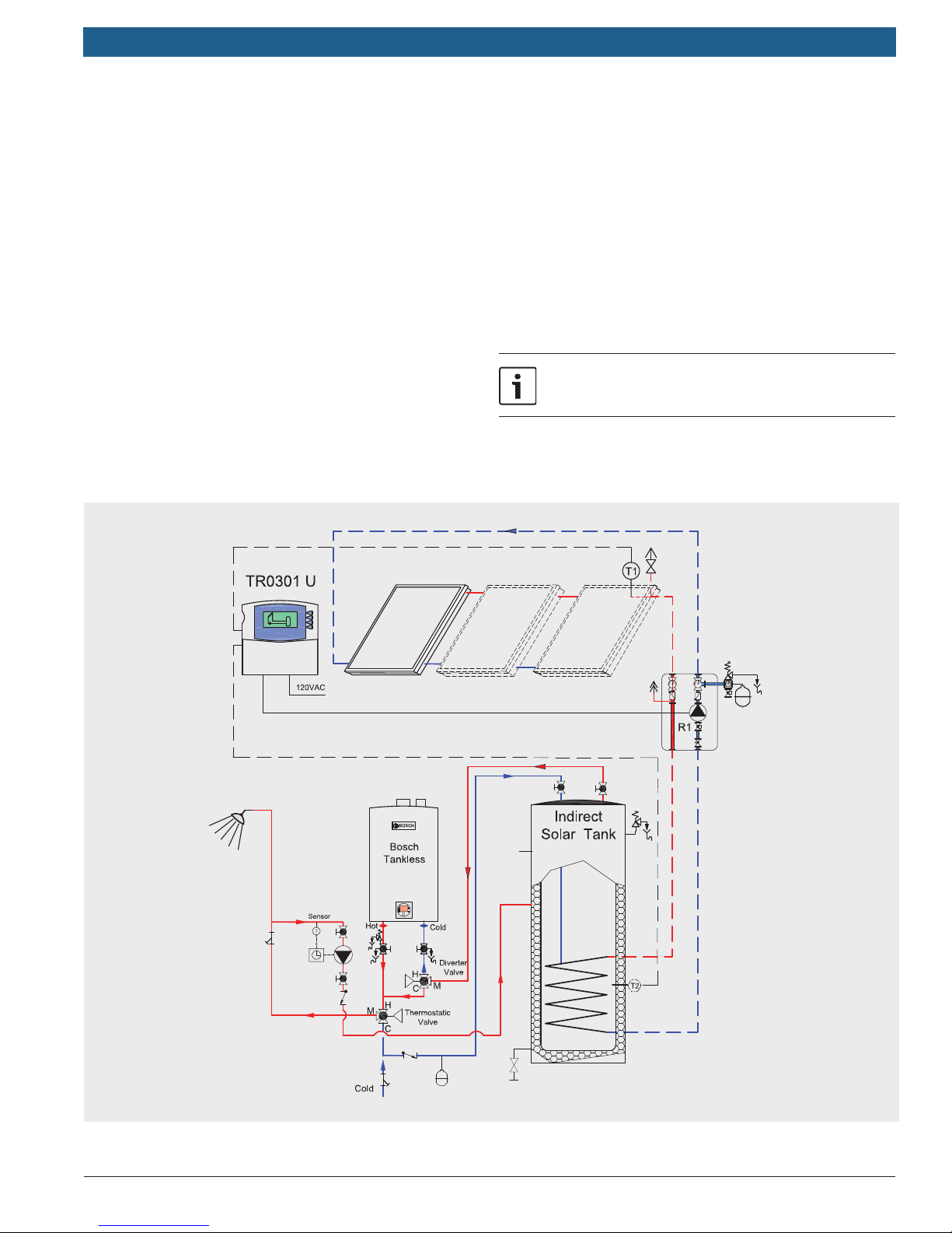
11.1.1 Solar DHW system with gas tankless water heater
booster
The tankless water heater only runs when solar water
needs a boost. See applicable models listed in the figure
below.
f Thermostatic valve 1 ensures that warm solar water
bypasses the water heater and directs cooler water
through the appliance when boosting is needed.
f Thermostatic valve 2 acts as a tempering valve that
brings potentially hot water temperatures down to a
level that is safe for the inhabitants
Applicable models: Bosch 830 ES, 940 ES, 940 ESO,
C 950 ES, C 1050 ES, C 1210 ES.
System parameters:
f Honeywell AM101 Thermostatic Valves required for
proper operation;
f Remove check valves from Thermostatic Valve 1 as it is
used as a diverter valve;
f Thermostatic Valve 2 is a tempering valve;
f Recommended setpoint 120°F for both Valves;
f Set tankless water heater temperature to 140° F
Bosch Thermotechnology Corp.
Data subject to change
Page 28
|
28
THERM/GREENTHERM Tankless Water Heaters
Applications Manual
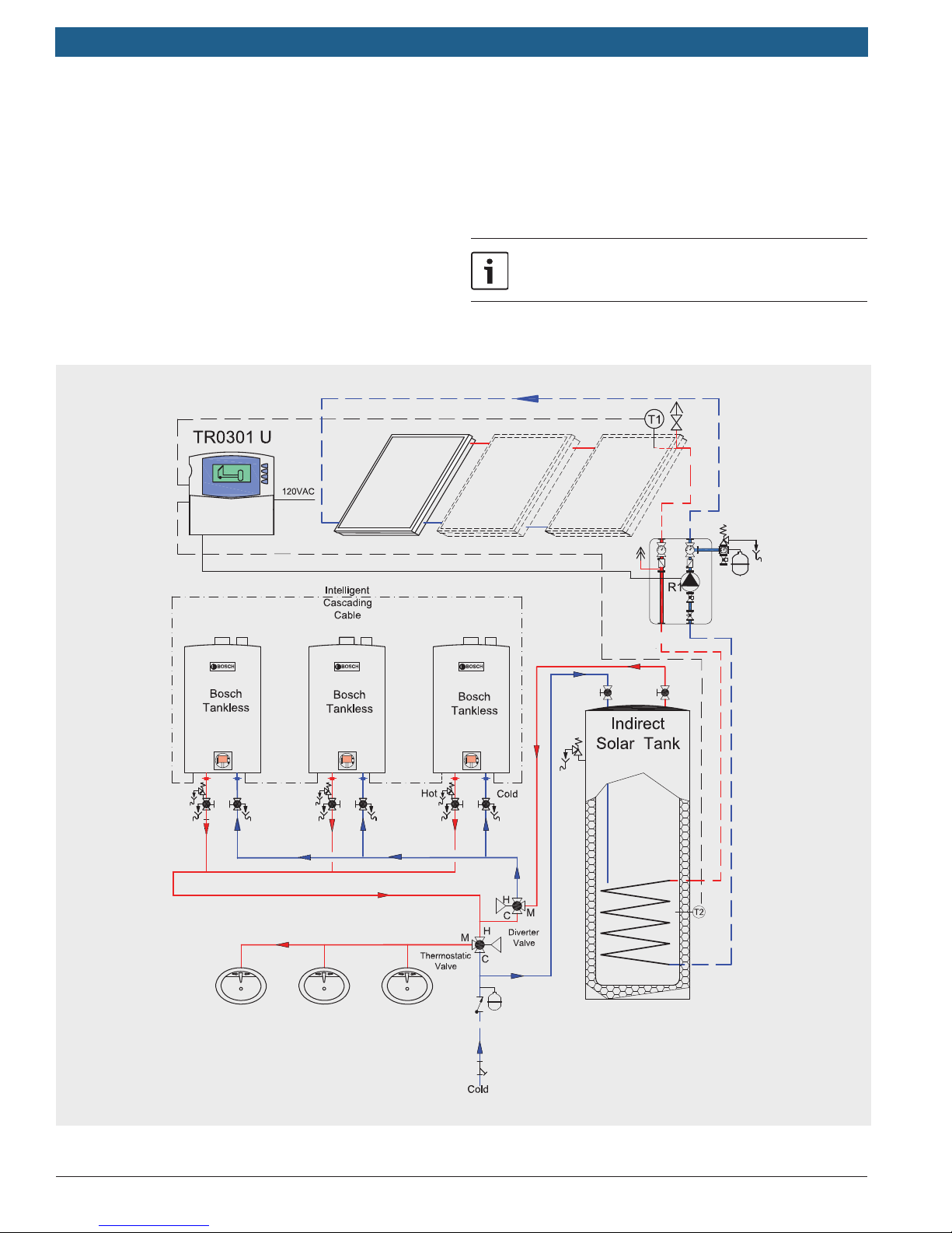
11.1.2 Solar DHW system with gas tankless water heater
booster and recirculation loop
Similar to 10.2.1 with domestic hot water recirculation
added. The tankless water heater only runs when solar
heated water needs a boost. See applicable models listed
below.
f Thermostatic valve 1 ensures that warm solar water
bypasses the water heater and directs cooler water
through the appliance when reheating is needed.
f Thermostatic valve 2 acts as a tempering valve that
brings potentially hot water temperatures down to a
level that is safe for the inhabitants
Applicable models: Bosch 830 ES, 940 ES, 940 ESO,
C 950 ES, C 1050 ES, C 1210 ES.
System parameters:
f Honeywell AM101 Thermostatic Valves required for
proper operation;
f Remove check valves from Thermostatic Valve 1 as it is
used as a diverter valve;
f Thermostatic Valve 2 is a tempering valve;
f Recommended setpoint 120°F for both Valves;
f Set tankless water heater temperature to 140° F
See Chapter 5.2 for recirculation pump parameters
Bosch Thermotechnology Corp.Data subject to change
Page 29
Applications Manual THERM/GREENTHERM Tankless Water Heaters | 29
12 Commercial Solar Applications
Introduction
This section provides a general overview for commercial
hot water systems in conjuction with solar water heating
(e.g. schools, tness centers). For additional system
details, consult the Bosch Solar Technical Guide.
Applicable models: Bosch 830 ES, 940 ES, 940 ESO,
C 950 ES, C 1050 ES, C 1210 ES.
System parameters:
f Honeywell AM101 Thermostatic Valves required for
proper operation;
See Chapter 5.2 for recirculation pump parameters
Bosch Thermotechnology Corp.
Data subject to change
Page 30

|
30
THERM/GREENTHERM Tankless Water Heaters
13 Commercial Water Heating
Applications
Introduction
This section gives a general overview of high volume, high
temperature water heating for commercial applications.
Applications Manual
Bosch Thermotechnology Corp.Data subject to change
Page 31
Applications Manual THERM/GREENTHERM Tankless Water Heaters | 31
13.1 Commercial Kitchen applications
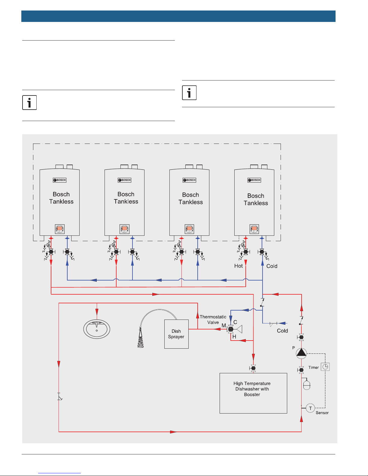
13.1.1 Commercial kitchen with domestic hot water
recirculation
Applicable models: Bosch 830 ES, 940 ES, 940 ESO,
C 950 ES, C 1050 ES, C 1210 ES, C 1210 ESC.
When using the super sprayer, hot water draws
must be longer than 15 seconds to avoid
temperature uctuations.
System parameters:
f For optimum performance in applications involving a
commercial dishwasher, a hot water circulation loop is
recommended.
See Chapter 5.2 for recirculation pump
parameters
Bosch Thermotechnology Corp.
Data subject to change
Page 32
|
32
THERM/GREENTHERM Tankless Water Heaters
Applications Manual
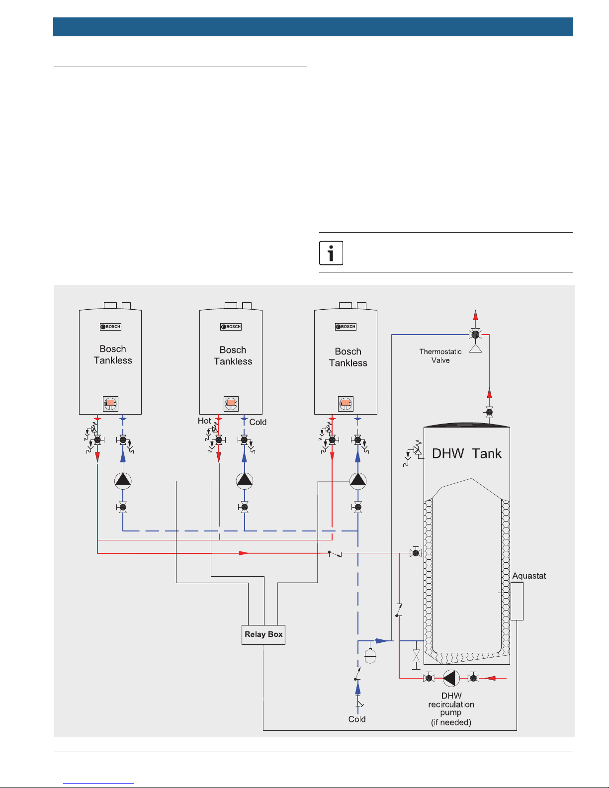
13.2 Tank loading with domestic hot water
recirculation
The following application outlines a tank loading
application for commercial hot water systems where
reliability is critical (e.g. hotels, tness centers). This
design allows for the isolation of the major system
components for service or in case of failure. The
redundant modular design allows continued system
operation even after a tank or pump or water heater
has failed. Domestic hot water recirculation through is
optional.
Do not use the Intelligent Cascading Kit in tank loading
applications.
Applicable models: Bosch 830 ES, 940 ES, 940 ESO,
C 950 ES, C 1050 ES, C 1210 ES, C 1210 ESC.
System parameters:
f Aquastat/tank sensor setpoint temperature 120-140°F,
<10°F differential.
f 30-119 gallon storage tank recommended.
f DHW return line can tie directly into tank if fittings are
available.
f Individual pumps can be used on supply to each
heater (as shown) or one pump for the entire system.
f Maintain a 20 degree difference between tankless
set-point and desired tank temperature.
See Chapter 5.2 for recirculation pump parameters
DHW
supply
DHW
return
Bosch Thermotechnology Corp.Data subject to change
Page 33
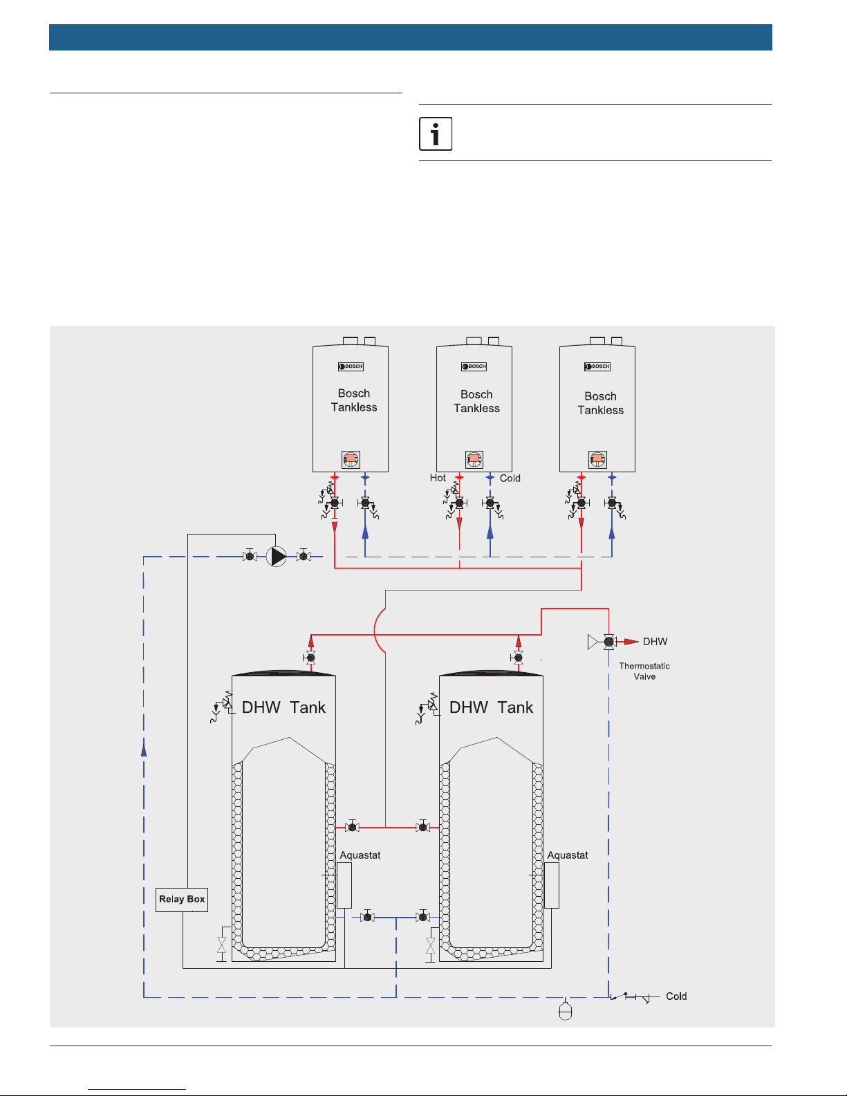
Applications Manual THERM/GREENTHERM Tankless Water Heaters | 33
13.3 Advanced tank loading commercial hot
water system
The following application outlines an advanced tank loading application for commercial hot water systems (e.g. hotels, fi tness
centers). This design allows for complete isolation of the system
for maintenance reasons and gives the ability to bypass certain
system components in case of failure. A second hot water storage tank is shown for additional hot water supply and back up
in case of tank failure.
Applicable models: Bosch 830 ES, 940 ES, 940 ESO,
C 950 ES, C 1050 ES, C 1210 ES, C 1210 ESC.
See Chapter 5.2 for recirculation pump parameters
System parameters:
f Maintain a 20 degree difference between tankless
set-point and desired tank temperature.
Bosch Thermotechnology Corp.
Data subject to change
Page 34

|
34
THERM/GREENTHERM Tankless Water Heaters
13.4 Common Venting
Up to 4 Greentherm C 950 ES and C 1050 ES or up to 4
Therm C 1210 ES/ESC can be common vented using the
new polypropylene modular venting system. A vertical
termination through a at or sloped roof and a horizontal
termination through the side wall are available.
Select from side by side or back to back con guration.
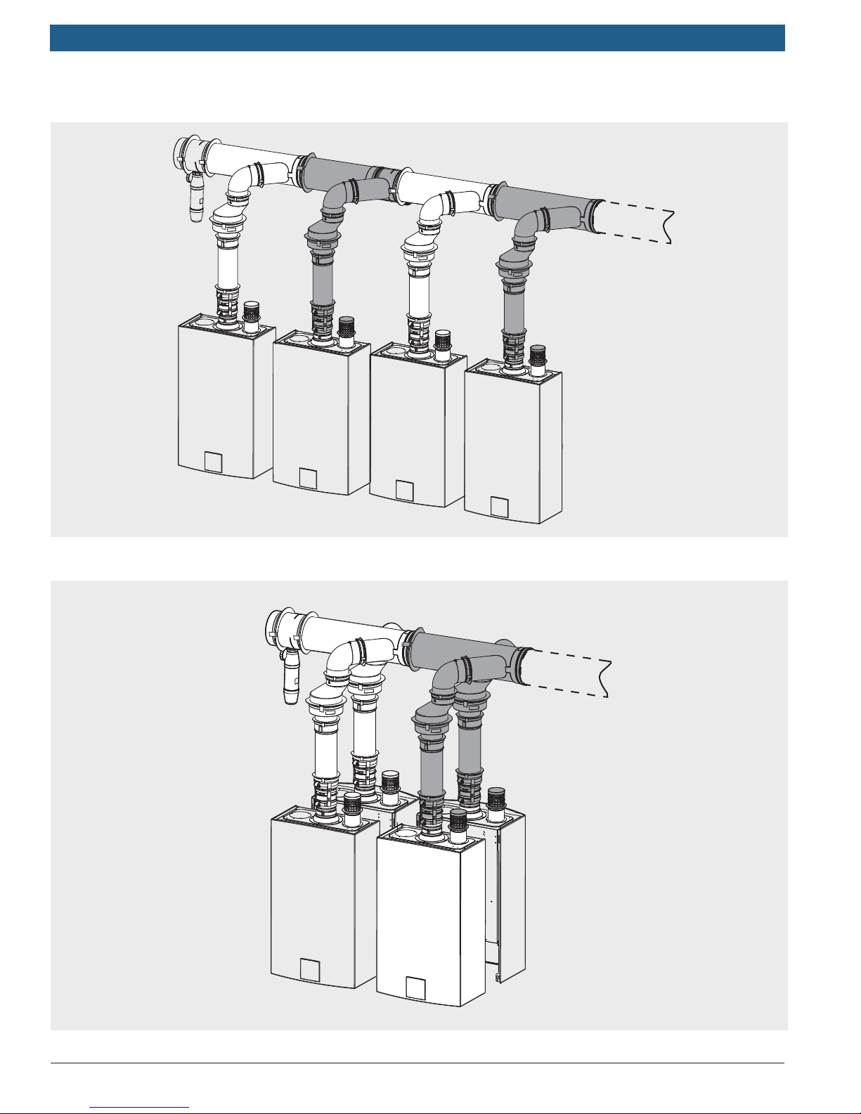
f Side by side:
— 2 units (1x Kit A)
— 3 units (1x Kit A + 1x Kit B)
— 4 units (1x Kit A + 2x Kit B)
The Basic Kit A includes all needed parts for 2 appliances.
Add one Extension Kit B for the third appliance, or two
Extension Kit B for a total of four units.
Applications Manual
f Back to back:
— 2 units (1x Kit C)
— 4 units (1x Kit C + 1x Kit D)
The Basic Kit C covers the rst two appliances. The
Extension Kit D covers both appliances three and four.
Choose the vertical or horizontal termination, and as many
rigid pipe pieces and elbows as needed, up to a maximum
equivalent length of 100' (30m) between the last appliance
and the termination.
f Equivalent length for
— 90° Elbow: 80"
— 45° Elbow: 40"
Bosch Thermotechnology Corp.Data subject to change
Page 35

Applications Manual THERM/GREENTHERM Tankless Water Heaters | 35
Tankless - Polypropylene Cascade Common Venting
Venting System Part Number
KIT A – Cascade Kit Side by Side Basic Units 1 and 2 (2 heaters) 7736501100
KIT B – Cascade Kit Extension Side by Side Units 3 and/or 4 (1 heater) 7736501254
KIT C – Cascade Set Back to Back Basic Units 1 and 2 (2 heaters) 7736501253
KIT D – Cascade Kit Extension Back to Back Units 3 and 4 (2 heaters) 7736501252
Horizontal Wall Terminal PP DIA6" 7736501117
Vertical Roof Terminal PP DIA6" 7736501119
Extension Rigid Pipe DIA6" x 80" 7736501133
Extension Rigid Pipe DIA6" x 40" 7736501135
Extension Rigid Pipe DIA6" x 20" 7736501137
Elbow DIA6" 90 7736501132
Elbow DIA6" 45 7736501146
Support Elbow DIA6" 7736501129
Extension Rigid Pipe DIA4" x 20" 7736501143
Extension Rigid Pipe DIA4" x 10" 7736501090
Elbow DIA4" 90 7736501141
Elbow DIA4" 45 7736501139
Chimney Connection DIA6" 7736501115
Wall Clamp DIA3" 7736501257
Wall Clamp DIA4" 7736501256
Wall Clamp DIA6" 7736501255
Flat Roof Flashing DIA6" 7736501095
PP Extension DIA4" 305 QF 7736501097
Steep Roof Flashing 0-25 DIA6" 7736501093
Steep Roof Flashing 25-45 DIA6" 7736501091
Wall Bracket DIA6" 7736501113
Bosch Thermotechnology Corp.
Data subject to change
Page 36
|
36
THERM/GREENTHERM Tankless Water Heaters
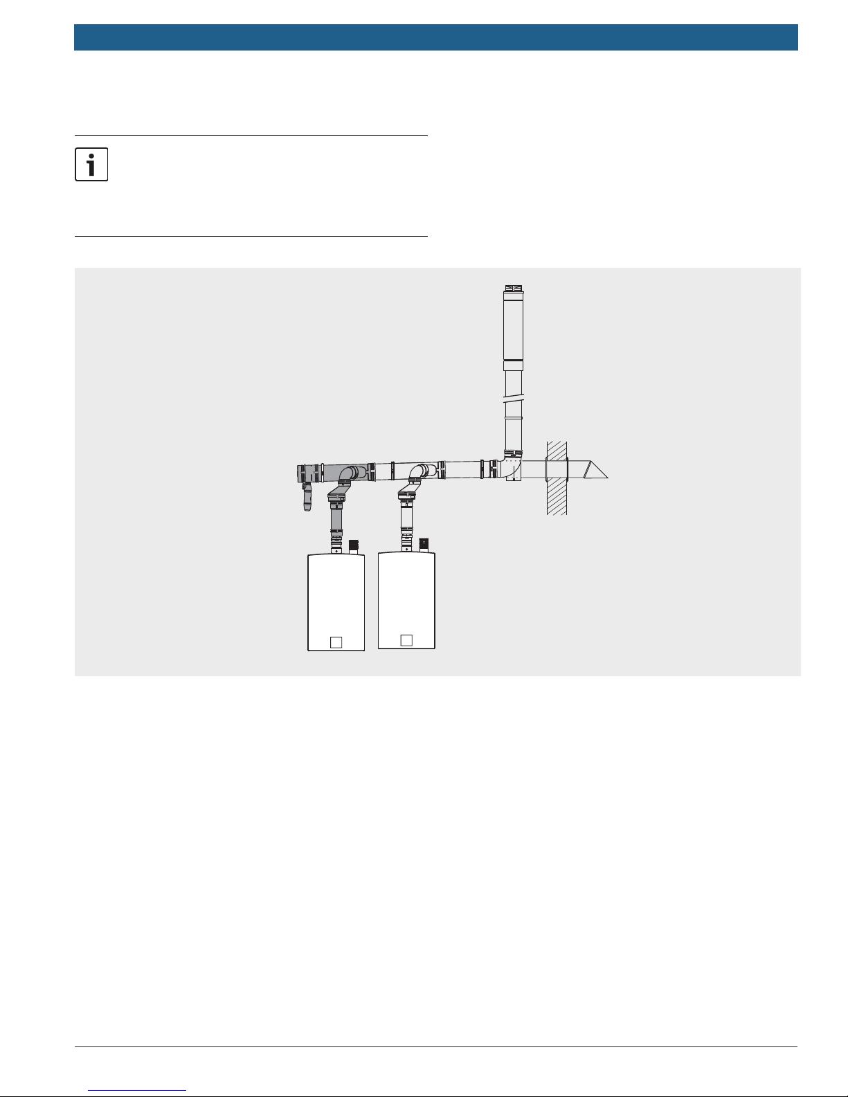
Common venting with vertical or horizontal termination
Schematic shows both vertical and horizontal
setup. 45° and 90° elbows can be used as needed.
The vent pipe must over its full length be sloped
toward the water heaters and low points are not
permitted.
Applications Manual
Bosch Thermotechnology Corp.Data subject to change
Page 37
Applications Manual THERM/GREENTHERM Tankless Water Heaters | 37
Side by side con guration
Back to back con guration
Bosch Thermotechnology Corp.
Data subject to change
Page 38

|
38
THERM/GREENTHERM Tankless Water Heaters
Applications Manual
Bosch Thermotechnology Corp.Data subject to change
Page 39

Applications Manual THERM/GREENTHERM Tankless Water Heaters | 39
Bosch Thermotechnology Corp.
Data subject to change
Page 40

United States and Canada
Bosch Thermotechnology Corp.
50 Wentworth Avenue
Londonderry, NH 03053
Tel: 866-330-2730
Fax: 603-965-7581
www.bosch-climate.us
BTC 740001301 E / 03.2013
 Loading...