

Page 1
CATALOG U E 2 004/200 5
HIGH-FREQUENCY POWER TOOLS
FOR INDUSTRY
www.boschproductiontools.com
TOP
P ERFO RMAN C E WITH THE
LOWEST P OSS IBL E
ENERGY CONSUM PTION.
PRODUCTION TOOLS
Ideas that work.
Page 2
45-58
2 3
63-75
5-12
13-44
Selection Guide for Drills . . . . . . . . . . . . . . . . . . . . . . . . . . . . . . . . . . . . . .6
Drills . . . . . . . . . . . . . . . . . . . . . . . . . . . . . . . . . . . . . . . . . . . . . . . . . . . . . . . .8
Accessories . . . . . . . . . . . . . . . . . . . . . . . . . . . . . . . . . . . . . . . . . . . . . . . . .10
Dimensional Drawings . . . . . . . . . . . . . . . . . . . . . . . . . . . . . . . . . . . . . . .11
Selection Guide for Sanders . . . . . . . . . . . . . . . . . . . . . . . . . . . . . . . . . .14
Straight Grinders . . . . . . . . . . . . . . . . . . . . . . . . . . . . . . . . . . . . . . . . . . . .18
Angle Grinders . . . . . . . . . . . . . . . . . . . . . . . . . . . . . . . . . . . . . . . . . . . . . .28
Disc Sanders . . . . . . . . . . . . . . . . . . . . . . . . . . . . . . . . . . . . . . . . . . . . . . . .34
Accessories . . . . . . . . . . . . . . . . . . . . . . . . . . . . . . . . . . . . . . . . . . . . . . . . .36
Dimensional Drawings . . . . . . . . . . . . . . . . . . . . . . . . . . . . . . . . . . . . . . .38
CONT ENTS.
DR ILLS
GRINDERS
Selection Guide for Screwdrivers . . . . . . . . . . . . . . . . . . . . . . . . . . . . . .46
Shut-off Screwdriver . . . . . . . . . . . . . . . . . . . . . . . . . . . . . . . . . . . . . . . . .4 8
Impact Wrenches . . . . . . . . . . . . . . . . . . . . . . . . . . . . . . . . . . . . . . . . . . . .50
Tappers . . . . . . . . . . . . . . . . . . . . . . . . . . . . . . . . . . . . . . . . . . . . . . . . . . . .52
Accessories . . . . . . . . . . . . . . . . . . . . . . . . . . . . . . . . . . . . . . . . . . . . . . . . .54
Dimensional Drawings . . . . . . . . . . . . . . . . . . . . . . . . . . . . . . . . . . . . . . .55
SC REWD RIVE R S AND TAPP ER S
High-frequency technology correctly applied . . . . . . . . . . . . . . . . . . . .64
59-62
ACCESSORIES
Balancers . . . . . . . . . . . . . . . . . . . . . . . . . . . . . . . . . . . . . . . . . . . . . . . . . . .60
Plug-in Connections and Lines . . . . . . . . . . . . . . . . . . . . . . . . . . . . . . . .62
HIGH-FREQUENCY TECHNOLOGY
All of the air tools listed in this
catalogue meet the following
standards or norm documents
EN 792, EN 50144, in accordance
with the regulations of Directives
89/392/EEC.
Conformity
Better performance through
higher frequency
Because their carbon brushes are
subject to wear, universal motors of
conventional power tools are unable
to satisfy these requirements.On the
other hand, the brushless asynchronous motor is ideally suited.
The current frequency it is supplied
with determines its rotational speed,
which, in turn, determines the output that can be achieved.A higher
frequency therefore means a higher
speed and a higher output.
High power at a constant
speed
In continuous operation at 300 Hz,
Bosch high-frequency tools have a
power output of up to 400 Watts
per kg machine weight. In the short
term, peak perfor mances of up to
2.5 times this value are possible.
The speed remains almost constant
– irrespective of whether the tool is
being operated at idle or full load.
Unique
economy
A further argument in favour of
high-frequency tools: their economy. Their efficiency and thus their
power consumption means that
they have unrivalled economy.
Their long service life and low
maintenance requirementsand
power consumption offer an economic solution for every type of
application.
Distinct environmental
consciousness
Environmental thinking plays a central role in all Bosch products:
from the initial development of the
idea and energy saving products, to
environmentally friendly packaging
and disposal.
If a Bosch high-frequency tool is
irreparably damaged, B osch will
take back the old tool.They are collected centrally in the service centre
and passed on for careful recycling.
Special power saving
measures
Bosch is also innovative in the
area of power saving and places an
emphasis on future-oriented technology: The heat recovery system
in the Murrhard plant,for example,
produces savings of over half a million litres of heating oil a year.
Information
from the Internet
Bosch now offers users and others
interested in industrial tools all current product information on the
Internet.Here you will find a free
online catalogue illustrating in text
and pictures all the common cordless, air and hig h-frequency tools for
industrial use. More information on
Pag e 4.
H IG H-F R EQU E N CY POWE R TOO LS:
I N EXP E NS IVE POWE R APP LI CATI ON.
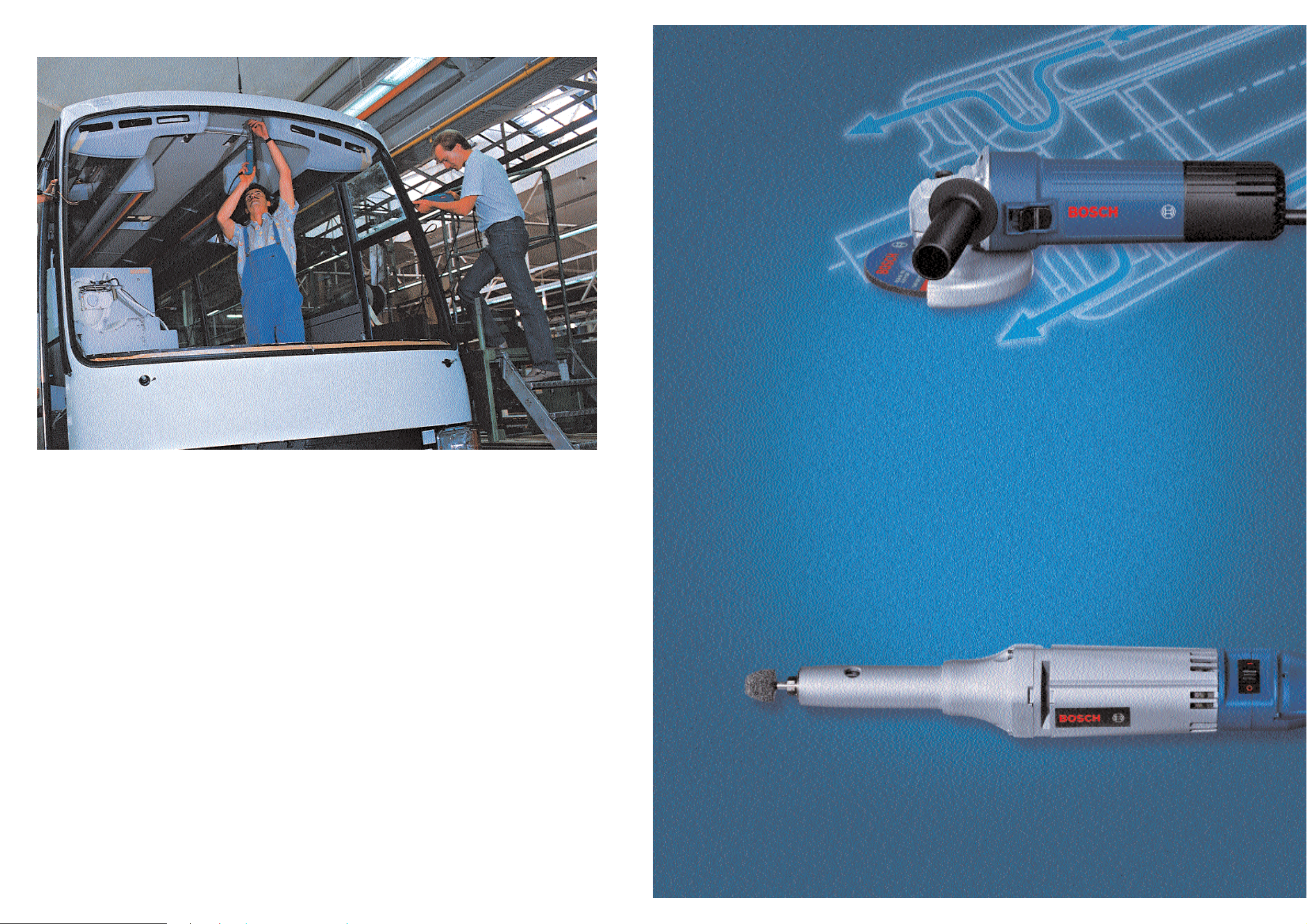
In spite of increasing automation in industrial production, the use of hand-held tools has
advantages in many work operations. These tools must fulfil several requirements: robustness,
powerful and a long service life, but they must also be easy to manage with high operating
comfort.
Certified in
accordance
with ISO 900 1
Certificate no. FM 3 0078
All weight data in this catalogue corresponds to the EPTA Procedure 01/2003.
Page 3
4
DRILLS
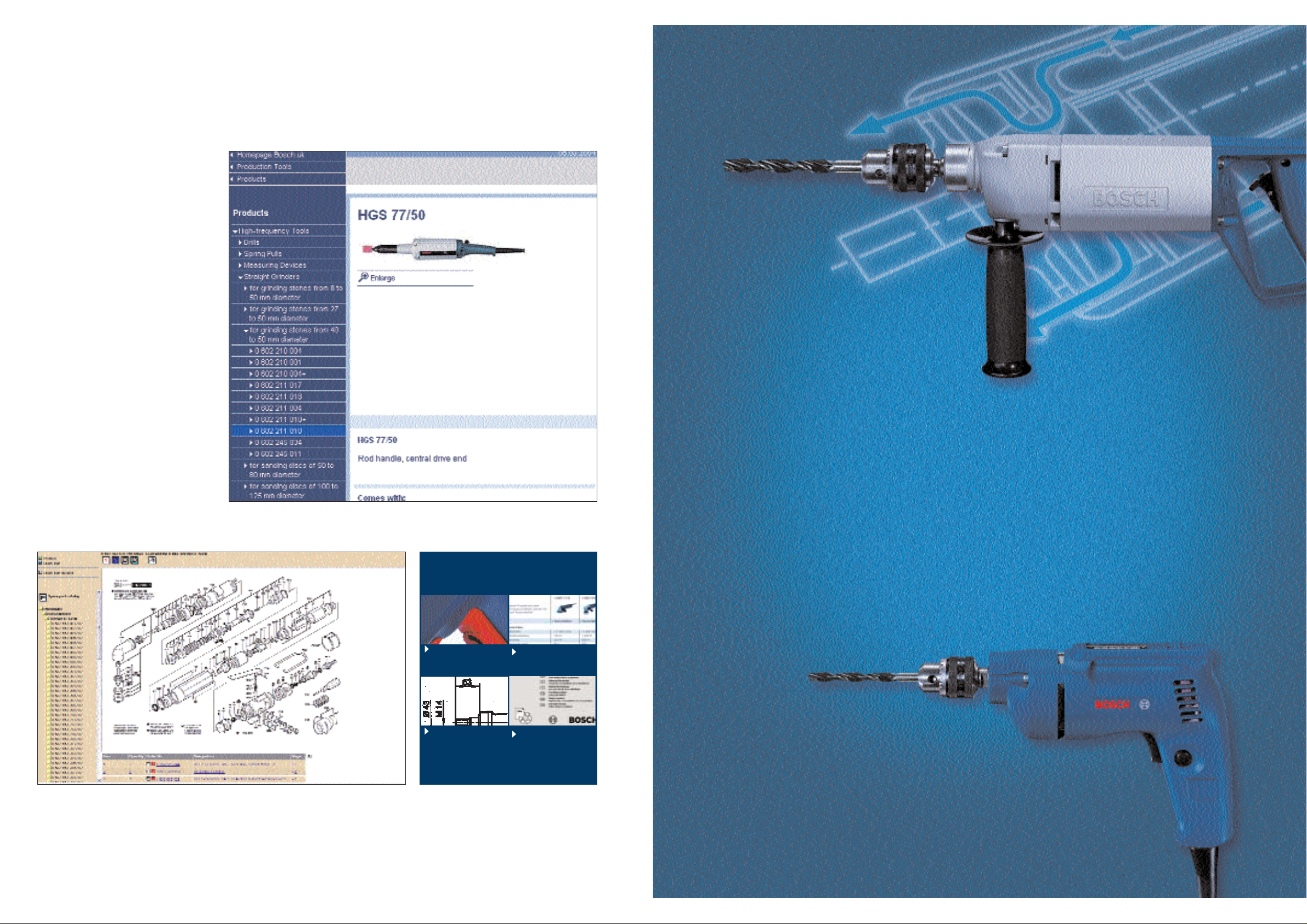
AN OVE RVI EW WITH A S I NG LE C LI CK:
ALL I N D USTR IAL TO OLS O N LI N E.
Everything the user needs to know
can now be found on the Internet:
under
www.boschproductiontools.com
the user has an extensive online
catalogue to find which products
are available and how they can be
applied. The selection of tools is
made easier by the possibilities to
run comparisons between tools.
Users,for example, can display all
high-frequency sanders and compare their respective data such as
output or rotational speed.Furthermore, they find out the latest news
about measurement data, innovations and new developments from
the area of Bosch Industrial Tools.
Within a short time,this provides
users with all the relevant information they need to select the
correct production tools.
Operating instructions, pictures and exploded drawings can be downloaded directly
from the Internet.
A spare parts service informs users about which spare parts they need – and where they can
order them.
Service
Product
Picture
Product
Comparison
Dimensioned
drawing
Instruction
manual
Page 4

Order number
Brass, copper,
bronze
Aluminium
Silumin
Cast iron up tp
300 N/mm2plastic
Cast iron up to
180 N/mm
2
Seel over
600 N/mm
2
Frequency
Speed [rpm]
Seel up to
600 N/mm
2
0 602 135 001 / ...004
0 602 135 101 /...104
0 602 135 104
0 602 117 001/ ...004 / ...008
0 602 117 004
Cutting speed [m/min]:
200
300
200
300
2450
3700
1350
2000
0 602 120 101/ ...10 4 /...107
0 602 120 104
0 602 121 101/...104 /...107
0 602 121 104
20 to 25 15 to 20 20 to 30 10 to 20 50 to 60 30 to 40 80 to 120
2 4 6 8 10 12 1416 18202224
200
300
200
200
300
200
1350
2050
690
1000
1030
3300
200
200
200
200
300
300
1600
2400
900
1500
1500
2200
1. gear
2. gear
1. gear
2. gear
1. gear
2. gear
0 602 131 101/...104/...107
0 602 131 104
0 602 133 101 / ...104
0 602 133 107
0 602 133 104
0 602 134 101
200
300
510
760
0 602 119 001 / ...004 / ...008
0 602 119 004
200
200
300
300
216
512
328
775
1. gear
2. gear
1. gear
2. gear
Drill diameter (mm)
2 4 6 8 10 12 1416 18202224 2 4 6 8 10 12141618202224 2 4 6 8 10 1214 1618 20 2224 2 4 6 8 10 1214 1618 20 2224 2 4 6 8 1012 14 161820 2224 2 4 6 8 10 1214 161820 22 24
2 4 6 8 10 12 1416 18202224 2 4 6 8 10 121416 18202224 2 4 6 8 10 1214 161820 2224 2 4 6 8 10 1214 161820 2224 2 4 6 8 10 1 214161820 2224 2 4 6 8 101 214 161820 2224 2 4 6 8 10 12141618202224
2 4 6 8 10 12 1416 18202224 2 4 6 8 10 121416 18202224 2 4 6 8 10 1214 161820 2224 2 4 6 8 10 1214 161820 2224 2 4 6 8 10 1 214161820 2224 2 4 6 8 101 214 161820 2224 2 4 6 8 10 12141618202224
2 4 6 8 10 12 1416 18202224 2 4 6 8 10 121416 18202224 2 4 6 8 10 1214 161820 2224 2 4 6 8 10 1214 161820 2224 2 4 6 8 10 1 214161820 2224 2 4 6 8 101 214 161820 2224 2 4 6 8 10 12141618202224
2 4 6 8 10 12 1416 18202224 2 4 6 8 10 121416 18202224 2 4 6 8 10 1214 161820 2224 2 4 6 8 10 1214 161820 2224 2 4 6 8 10 1 214161820 2224 2 4 6 8 101 214 161820 2224 2 4 6 8 10 12141618202224
Selection of the rig ht drill depends
mainly on the following two points:
drill bit diameter and
the recommended cutting speed
of the material to be processed.
In the table, the preferred bit sizes
are assigned to the individual drill
types for some common materials.
The table shows the drill bit sizes
with which the individual types are
able to reach the recommended
cutting speeds. However, the feed
of hand-held tools cannot be increased arbitrarily with increasing bit
diameter, since the necessary feed
force can no longer be applied. For
this reason, the maximum bit diameters for steel and aluminium
are allocated to the individual types
on page 6. These maximum diameters were determined by tests,unlike the information in the table. In
order to achieve a sufficient cutting
speed with normal hand pressure,
some materials should be predrilled
for the following bit diameters:
steel upto 600 N/mm
2
as of 8 mm
steel upto 600 N/mm
2
as of 6 mm
cast iron up to 180 N/mm
2
as of
10 mm
cast iron up to 300 N/mm
2
as of
8 mm
Note: If only one bit diameter is
specified in the table, it refers to
the lower limit of the recommended cutting speed. If nothing is
specified, the recommended bit
diameter is outside the clamping
range of the standard chuck.
SE LECTION GU I DE FOR DR I LLS.
6 7
Page 5
8 9
Accessory
order number
Accessories supplied
Remarks
Speed settings
Motor size (mm)
Output drive tool-
holding fixture
Weight withouth calbe (kg)
Nominal current (A)
Nominal power
output (W)
Nominal power
consumption (W)
Idling
speed (min
-1
)
Max. bit-
l
in aluminium (mm)
Max. bit-
l
in steel (mm)
Frequecy (Hz)
Voltage (V)
Order number
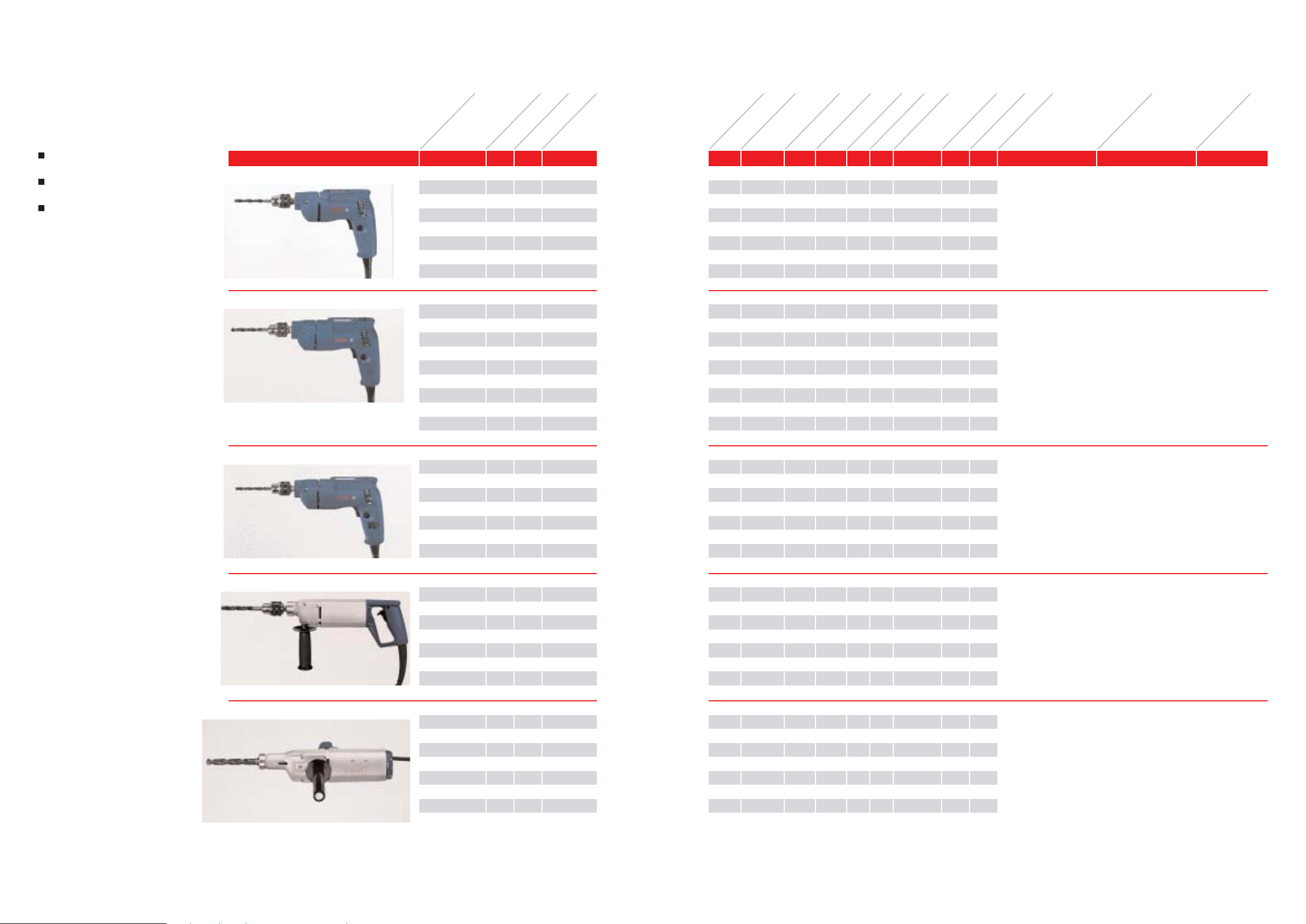
DR I LLS.
The suitable drills for a very wide
variety of materials
Drill at constant speed for optimised operational life
Motors with extremely long service
lives for economical work
HB M 55/1
0 602 120 101 265 200 3
0 602 120 104 135 200 3
0 602 120 107 72 200 3
0 602 120 104 200 300 2
0 602 121 101 265 200 6
0 602 121 104 135 200 6
0 602 121 107 72 200 6
0 602 121 104 200 300 4
3 608 571 0017 2450 260 150 0.9 1.7 1/2
HH-20 UNF 55 1
7 2450 260 150 1.7 1.7 1/2
HH-20 UNF 55 1
7 2450 260 150 3.2 1.7 1/2
HH-20 UNF 55 1
7 3700 400 230 1.7 1.7 1/2
HH-20 UNF 55 1
9 1350 260 140 0.9 1.7 1/2
HH-20 UNF 55 1
9 1350 260 140 1.7 1.7 1/2
HH-20 UNF 55 1
9 1350 260 140 3.2 1.7 1/2
HH-20 UNF 55 1
9 2000 400 230 1.7 1.7 1/2
HH-20 UNF 55 1
1-speed drill
with three-jaw chuck
Chuck with key
Clamping range 1–10 mm
HBM 57/1
0 602 131 101 265 200 6
0 602 131 104 135 200 6
0 602 131 107 72 200 6
0 602 131 104 200 300 4
0 602 133 101 265 200 9
0 602 133 104 135 200 9
0 602 133 107 72 200 8
0 602 133 104 200 300 8
0 602 134 101 265 200 2
3 608 571 001
3 608 571 004
10 1350 470 310 1.6 2.0 1/2HH-20 UNF 57 1
10 1350 470 310 3.3 2.0 1/2
HH-20 UNF 57 1
10 1350 470 310 6.1 2.0 1/2HH-20 UNF 57 1
10 2050 600 400 3.3 2.0 1/2
HH-20 UNF 57 1
10 690 470 310 1.6 2.0 1/2
HH-20 UNF 57 1
10 690 470 310 3.3 2.0 1/2
HH-20 UNF 57 1
10 1000 400 310 6.1 2.0 1/2
HH-20 UNF 57 1
10 1030 700 460 3.3 2.0 1/2
HH-20 UNF 57 1
6 3300 400 270 1.6 2.0 M 13 x 1 57 1
1-speed drill
with three-jaw chuck
1-speed drill with keyless
chuck
Chuck with key
Clamping range 1–10 mm
HBM 57/2
0 602 135 001 265 200 5/3
0 602 135 004 135 200 5/3
0 602 135 101 265 200 8/5
0 602 135 104 135 200 8/5
0 602 135 104 200 300 5/4
3 608 571 00110/8 1600/2400 400 270 1.6 2.0 1/2
HH-20 UNF 57 2
10/8 1600/2400 400 270 3.3 2.0 1/2
HH-20 UNF 57 2
10/8 900/1500 400 270 1.6 2.0 1/2
HH-20 UNF 57 2
10/8 900/1500 400 270 3.3 2.0 1/2
HH-20 UNF 57 2
10/8 1500/2200 600 400 3.3 2.0 1/2
HH-20 UNF 57 2
2-speed drill
with three-jaw chuck
Chuck with key
Clamping range 1–10 mm
HB M 65/1
0 602 117 001 265 200 13
0 602 117 004 135 200 13
0 602 117 008 72 200 13
0 602 117 004 200 300 10
1 608 571 027
1 602 025 022
13 510 600 440 1.6 2.8 Taper B 16 65 1
13 510 600 440 3.3 2.8 Taper B 16 65 1
13 510 600 440 5.9 2.8 Taper B 16 65 1
13 760 900 630 3.3 2.8 Taper B 16 65 1
1-speed drill with
speed handle.
Three-jaw chuck can be
ordered as a special
accessory.
Chuck
Clamping range 1.5 –13 mm
Additional handle
HBM 77/2
0 602 119 001 265 200 16/12
0 602 119 004 135 200 16/12
0 602 119 008 72 200 16/12
0 602 119 004 200 300 16/18
1 600 763 010
3 601 030 002
23 216/512 950 700 2.8 5.6 Morse Taper2 77 2
23 216/512 950 700 5.5 5.6 Morse Taper2 77 2
23 216/512 950 700 10.0 5.6 Morse Taper2 77 2
23 328/775 1450 1050 5.5 5.6 Morse Taper 2 77 2
2-speed drill with
cross handle.
Without chuck.
Suitable for bits with.
morse taper 2.
Three-jaw chuck can be
ordered as a special
accessory.
Tubular handlef (M 27 x 2)
Drill drift
The machines come equipped with a special 4-m-long cable without plug. Your specialist dealer can provide you with information on the complete set of quality accessories.
Page 6
Up to drill-ø
(mm)
Steel uo tp
600 N/mm
2
Seel over
600 N/mm
2
Cast iron up to
180 N/mm
2
Cast iron uo tp
300 N/mm2Brass,
copper,
bronze
Silumin
Aluminium
Cutting
speed (m/min):
20 to 25 15 to 20 20 to 35 10 to 20 5 0 to 60 3 0 to 40 80 to 120
4 2380 1600 2200 1200 4400 2800 8000
5 1900 1270 1800 950 3500 2200 6400
6 1600 1060 1500 800 2900 1850 5300
7 1360 910 1300 680 2500 1600 4550
8 1200 800 1100 600 2200 1400 4000
9 1060 700 1000 530 1900 1200 3540
10 950 640 890 480 1700 1100 3200
11 860 580 810 430 1600 1000 2900
12 800 530 740 400 1500 930 2660
13 730 490 680 370 1350 860 2450
14 680 450 640 340 1250 800 2270
15 630 420 600 320 1150 740 2120
16 600 400 560 300 1100 700 2000
17 560 380 520 280 1050 660 1870
18 530 350 500 260 1000 620 1770
19 500 330 470 250 950 590 1680
20 480 320 450 240 900 560 1600
23 410 280 390 210 760 480 1380
30 310 210 300 160 580 370 1060
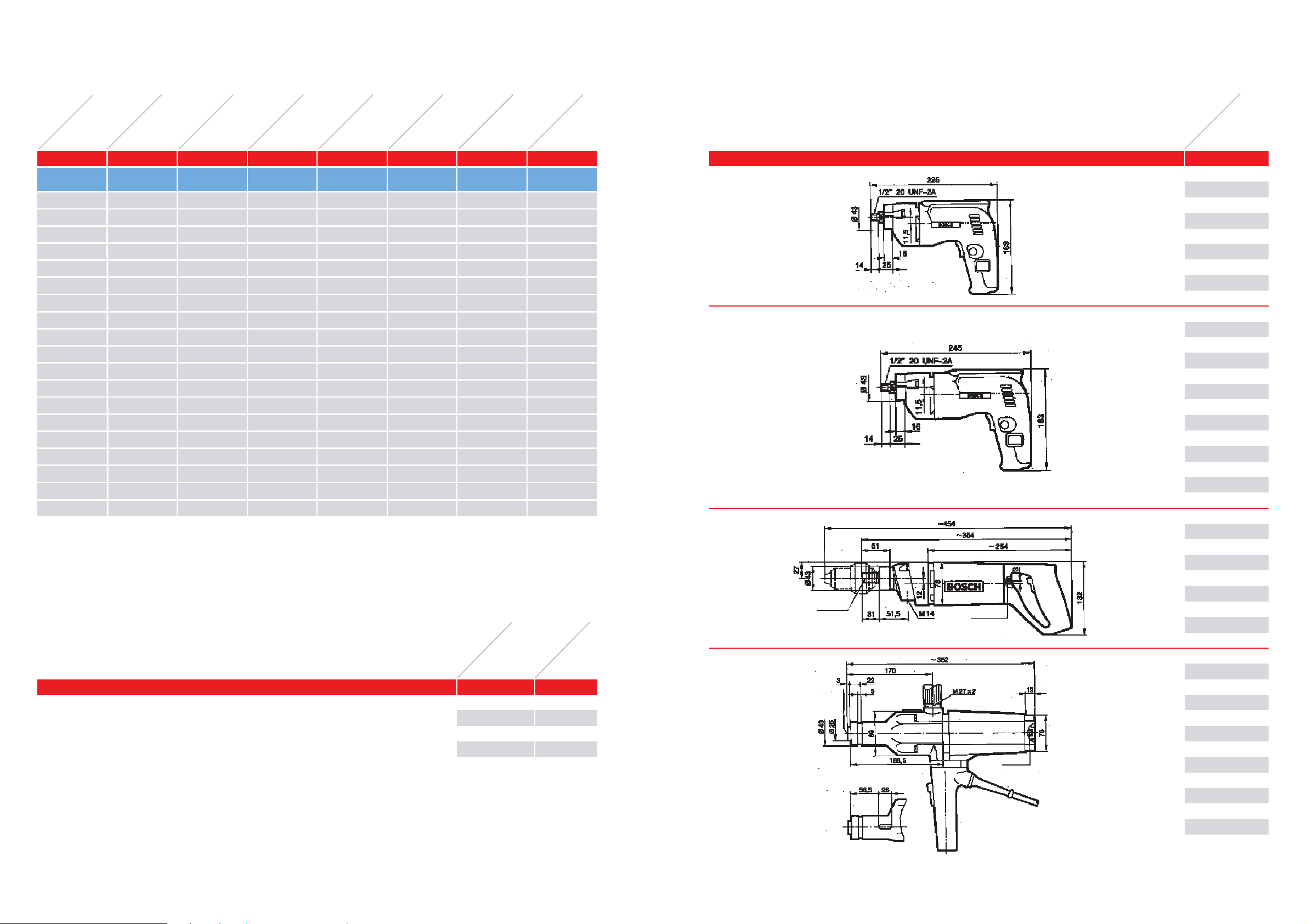
DI ME NS IO NAL DRAWI N GS: D R I LLS.
Order number
Size in mm
0 602 120 101
0 602 120 104
0 602 120 107
0 602 121 101
0 602 121 104
0 602 121 107
0 602 131 101
0 602 131 104
0 602 131 107
0 602 133 101
0 602 133 104
0 602 133 107
0 602 134 101
0 602 135 001
0 602 135 004
0 602 135 101
0 602 135 104
0 602 119 001
0 602 119 004
0 602 119 008
0 602 117 001
0 602 117 004
0 602 117 008
l 6;8 deep
Inner Tapper M K2
l 6;8 deep
Tapper B16
DIN 238
Please consult your stockist for information on the complete range of quality accessories.
ACCESSORI ES FOR DRI LLS.
Morse taper MK2 on B 16 for using drill chucks with clamping diameters up to
16 mm, B16.
Order number
Packing unit
1 603 115 002 1
10 11
RECOMMENDED SPEEDS FOR HSS TWIST DRILL
BITS.
Page 7
12
GRINDERS
Page 8
With grinding points
With tapered
grinding wheels
With straight
grinding wheels
14
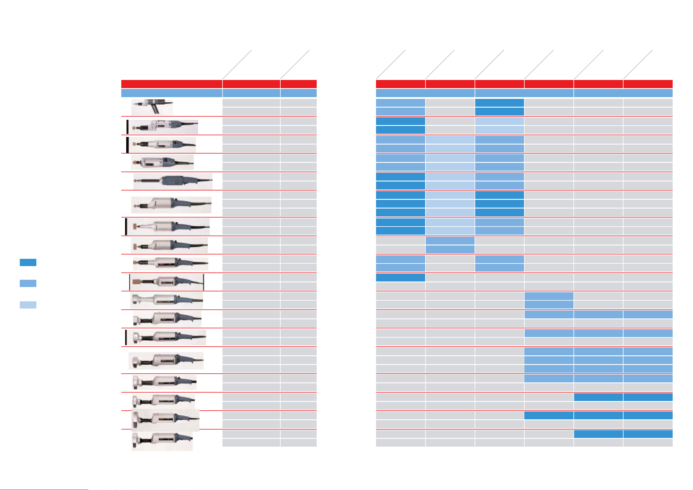
SELECTION GUIDE FOR GRINDERS.
Order number
Idle speed
(rpm)
optimally suited
for this application
well suited
for this application
suited for this
for this application
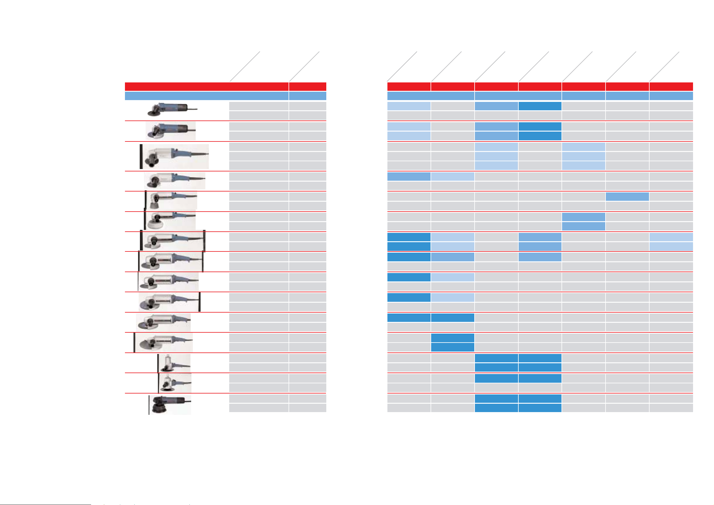
Please observe manufacturer’s
information regarding grinding
material.
In order to select the correct grinding machine, you must take the
area of application and specific
circumstances into consideration.
That is to say, selection of a gr inding point predetermines selection
of the suitable g rinder. In both
tables – one for straight grinders
and one for angle grinders – the
machines have been ordered to the
grinding tasks or grinding points
for which they are appropriate.
The more powerful the machine,
the larger the amount of material
that is removed.Because of the
great variety in individual working
conditions and spatial considerations, these recommendations can,
however, only serve as guidelines.
In any case,when selecting a grinder,you should take other product
features into consideration in addition to performance.
With fan-shaped
abrasives
With grinding points
With tapered
grinding wheels
0 602 226 2...
0 602 227 2...
0 602 228 2... / 3...
0 602 228 2... / 3...
0 602 229 1...
0 602 229 1...
0 602 238 1...
0 602 238 1...
0 602 207 0...
0 602 208 0...
0 602 208 0...
0 602 209 1...
0 602 209 1...
0 602 210 0...
0 602 210 0...
0 602 211 0...
0 602 211 0...
50 000
50 000
30 500
29 000
12 000
18 000
12 000
18 000
23 400
18 300
27 400
12 000
18 000
3 100
4 700
12 000
18 000
0 602 245 0... 18 000
0 602 211 1...
0 602 211 1...
12 000
18 000
0 602 243 1... 10 700
9 000
0 602 242 1...
0 602 242 1...
0 602 242 4...
0 602 213 1...
8 600
6 800
6 800
6 800
0 602 240 1... 5 700
0 602 240 0...
0 602 239 1...
10 200
4 800
12 000
18 000
Form grinding and deburring Interior processing Coarse grinding
0 602 225 1... / 2...
0 602 233 2... / 3...
0 602 212 1...
15
Page 9
With cup brushes
SELECTION GUIDE FOR GRINDERS,
DI SC AN D RAN D OM O R B IT SAND E RS.
1716
With grinding wheels
With fan-shaped
wheels
With lamb skin
covers
With cutting wheels
With fibre wheels
With grinding stone
Order number
Idle speed (rpm)
0 602 234 3...
0 602 234 3...
0 602 234 3...
4800
5 800
7 300
0 602 326 2...
0 602 305 0...
0 602 228 3...
0 602 228 3...
0 602 305 0...
0 602 306 0...
0 602 304 0...
0 602 304 0...
0 602 331 0...
0 602 332 0...
0 602 331 0...
0 602 334 1...
0 602 335 0...
0 602 335 0...
9 000
0 602 329 0...
1 750
1 750
1 650
5 700
8 600
8 500
6 600
6 600
6 600
4 700
5 100
0 602 373 0...
0 602 373 0...
3 600
5 400
0 602 370 1... 6 000
0 602 370 3...
0 602 370 3...
5 800
7 300
8 500
0 602 301 2...
0 602 301 2...
0 602 327 0...
4 100
6 150
2 550
Coarse grinding Coarse polishing (sanding) Polishing Wet grinding Brushing
Page 10
19
Accessory
Part number
Comes complete
with
Remarks
Switch
type
Toolholding
fixture
Collet chuck (mm)
Weight without
cabel (kg)
Nominal current (A)
Nominal power
Output (W)
Nominal power
consumption (W)
No load speed
(rpm)
Admissible
grinding point-
l
(mm)
Frequency (Hz)
Voltage (V)
Order number
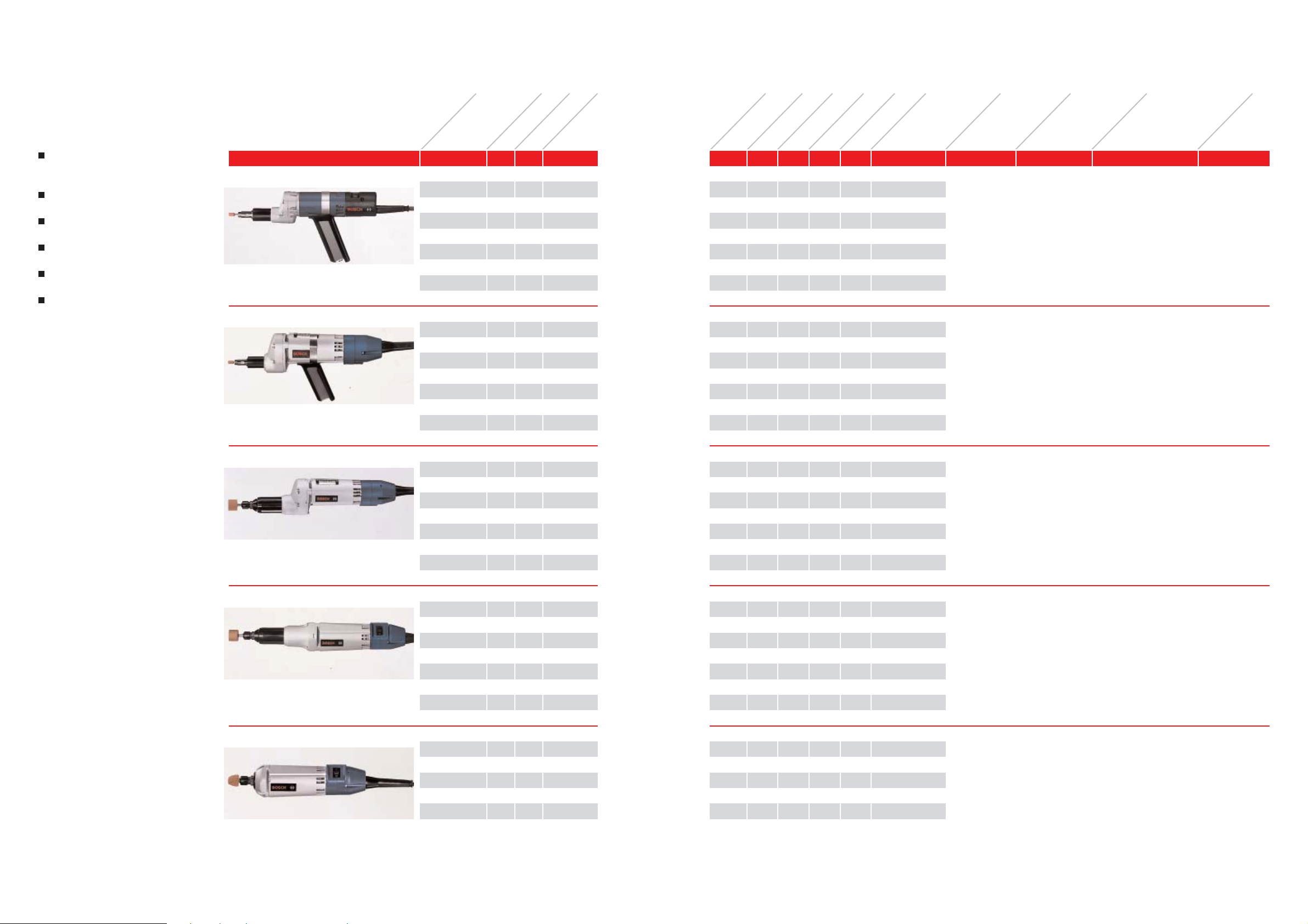
STRAIGHT GRINDERS.
The optimised straight grinders in
all power classes for the widest possible variety of applications
The ideal structural shape for ergonomic work
Constant speed, even at extremely
high loads
Efficient work with longest possible
service life
Robust motors with long service
lives and low maintenance costs
Extremely favourable weight-performance ratio
2 608 570 019
1 907 950 503
1 907 950 505
3 602 025 002
0 602 225 101 265 200 8
0 602 225 104 135 200 8
0 602 225 107 72 200 8
0 602 225 204 200 300 8
0 602 225 211 72 300 8
0 602 233 201 265 200 8
0 602 233 204 135 200 8
0 602 233 207 72 200 8
0 602 233 304 200 300 8
0 602 226 201 265 200 25
0 602 226 204 135 200 25
0 602 226 207 72 200 25
0 602 227 204 200 300 25
0 602 227 211 72 300 25
0 602 228 201 265 200 50
0 602 228 204 135 200 50
0 602 228 207 72 200 50
0 602 228 204 200 300 50
0 602 228 211 72 300 50
0 602 229 101 265 200 50
0 602 229 104 135 200 50
0 602 229 104 200 300 50
50 000 80 40 0.2 0.7 3
50 000 80 40 0.5 0.7 3
50 000 80 40 0.9 0.7 3
50 000 125 65 0.5 0.7 3
50 000 125 65 1.4 0.7 3
Collet chuck 3 mm
Open-ended spanner SW 9
Open-ended spanner SW 11
Auxiliary handle
Bar handle,
offset output drive
Slide switch
HGS 44/8
2 608 570 019
1 907 950 503
1 907 950 505
3 602 025 002
50 000 26 0 150 0.9 1.7 3
50 000 26 0 150 1.7 1.7 3
50 000 26 0 150 3.2 1.7 3
50 000 4 00 230 1.7 1.7 3
Collet chuck 3 mm
Open-ended spanner SW 9
Open-ended spanner SW 11
Auxiliary handle
Bar handle,
offset output drive
Slide switch
2 608 570 079
2 607 950 511
30 500 26 0 150 0.9 1.6 6
30 500 26 0 150 1.7 1.6 6
30 500 26 0 150 3.2 1.6 6
29 000 400 230 1.7 1.6 6
29 000 400 230 4.6 1.6 6
Collet chuck 6 mm
2 open-ended spanner
SW 17
Bar handle,
offset output drive
Slide switch
2 608 570 079
2 607 950 511
12 000 260 150 0.9 1.6 6
12 000 260 150 1.7 1.6 6
12 000 260 150 3.2 1.6 6
18 000 400 230 1.7 1.6 6
18 000 400 230 4.6 1.6 6
Collet chuck 6 mm
open-ended spanner SW 17
Bar handle,
central output drive
Slide switch
2 608 570 079
2 607 950 511
12 000 260 150 0.9 1.3 6
12 000 260 150 1.7 1.3 6
18 000 400 230 1.7 1.3 6
Collet chuck 6 mm
with nut
open-ended spanner SW 17
Bar handle,
central output drive,
short spindle
for tight spaces
Slide switch
for grinding points
8 to 50 mm in diameter
Your specialist dealer can provide you with information on the complete set of quality accessories.The machines come equipped with a special 4-m-long cable without plug.
HGS 55/8
HGS 55/25
HGS 55/5 0
HGS 55/5 0
18
Page 11
2120
Order number
Voltage (V)
Frequency (Hz)
Admissible
grinding point-
l
(mm)
No load speed
(rpm)
Nominal power
consumption (W)
Nominal power
Output (W)
Nominal current (A)
Weight without
cabel (kg)
Toolholding
fixture
Collet chuck (mm)
Switch
type
Remarks
Comes complete
with
Accessory
Part number
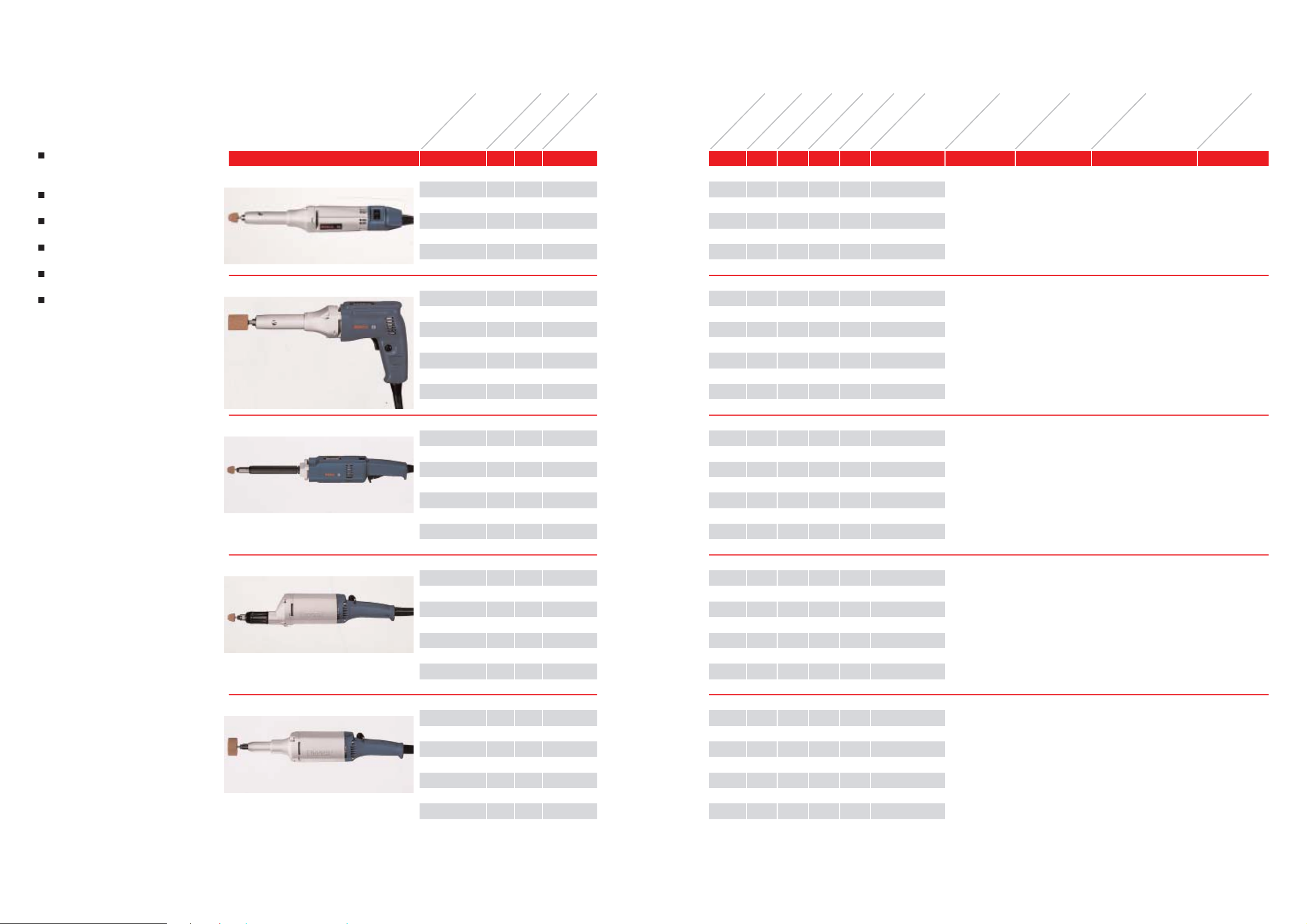
STRAIGHT GRINDERS.
The optimised straight grinders in
all power classes for the widest possible variety of applications
The ideal structural shape for ergonomic work
Constant speed, even at extremely
high loads
Efficient work with longest possible
service life
Robust motors with long service
lives and low maintenance costs
Extremely favourable weight-performance ratio
1 608 570 025
1 607 950 001
0 602 228 361 265 200 50
0 602 228 364 135 200 50
0 602 228 364 200 300 50
0 602 228 371 265 200 50
0 602 228 374 135 200 50
0 602 228 377 72 200 5 0
0 602 228 374 200 300 40
0 602 238 101 265 200 50
0 602 238 104 135 200 50
0 602 238 107 72 200 50
0 602 238 134 200 300 50
0 602 238 111 72 300 50
0 602 207 001 265 200 32
0 602 207 004 135 200 32
0 602 207 008 72 200 32
0 602 208 001 135 200 50
0 602 208 001 200 300 27
0 602 209 101 265 200 50
0 602 209 104 135 200 50
0 602 209 107 72 200 50
0 602 209 134 200 300 50
0 602 209 111 72 300 50
12 000 260 150 0.9 1.6 6
12 000 260 150 1.7 1.6 6
18 000 400 230 1.7 1.6 6
Collet chuck
l 6 mm
Offset screwdriver
Bar handle,
central output drive
with eccentric
clamping
ON/OF F switch
HGS 55/5 0
1 608 570 025
1 607 950 001
12 000 260 150 0.9 1.6 6
12 000 260 150 1.7 1.6 6
12 000 260 150 3.2 1.6 6
18 000 400 230 1.7 1.6 6
Collet chuck
l 6 mm
Offset screwdriver
Pistol handle,
with eccentric
clamping
Pressure switch
with lock
1 608 570 025
1 907 950 506
1 907 950 509
12 000 400 270 1.6 2.1 6
12 000 400 270 3.3 2.1 6
12 000 400 270 6.1 2.1 6
18 000 600 400 3.3 2.1 6
18 000 600 400 9.2 2.1 6
Collet chuck
l 6 mm
Open-ended spanner SW 12
Open-ended spanner SW 15
Post handle,
central output drive
Spindle length up to
480 mm optional.
Pressure switch
with lock
1 608 570 025
1 907 950 506
1 907 950 509
23 400 6 00 440 1.6 2.4 6
23 400 6 00 440 3.3 2.4 6
23 400 6 00 440 5.9 2.4 6
18 300 6 00 440 3.3 2.4 6
27 400 900 630 3.3 2.4 6
Collet chuck
l 6 mm
Open-ended spanner SW 12
Open-ended spanner SW 15
Post handle,
central output drive
Toggle
1 608 570 025
1 907 950 506
1 907 950 509
12 000 600 44 0 1.6 2.5 6
12 000 600 44 0 3.3 2.5 6
12 000 600 44 0 5.9 2.5 6
18 000 900 630 3.3 2.5 6
18 000 900 630 8.8 2.5 6
Collet chuck
l 6 mm
Open-ended spanner SW 12
Open-ended spanner SW 15
Post handle,
central output drive
Toggle
for grinding points
27 to 50 mm in diameter
The machines come equipped with a special 4-m-long cable without plug.
HGS 55/5 0
HGS 57/50 Ls
HGS 65/32
HGS 65/5 0
Your specialist dealer can provide you with information on the complete set of quality accessories.
Page 12
2322
Accessory
Part number
Comes complete
with
Remarks
Switch
type
Toolholding
fixture
Collet chuck (mm)
Weight without
cabel (kg)
Nominal current (A)
Nominal power
Output (W)
Nominal power
consumption (W)
No load speed
(rpm)
Admissible
grinding point-
l
(mm)
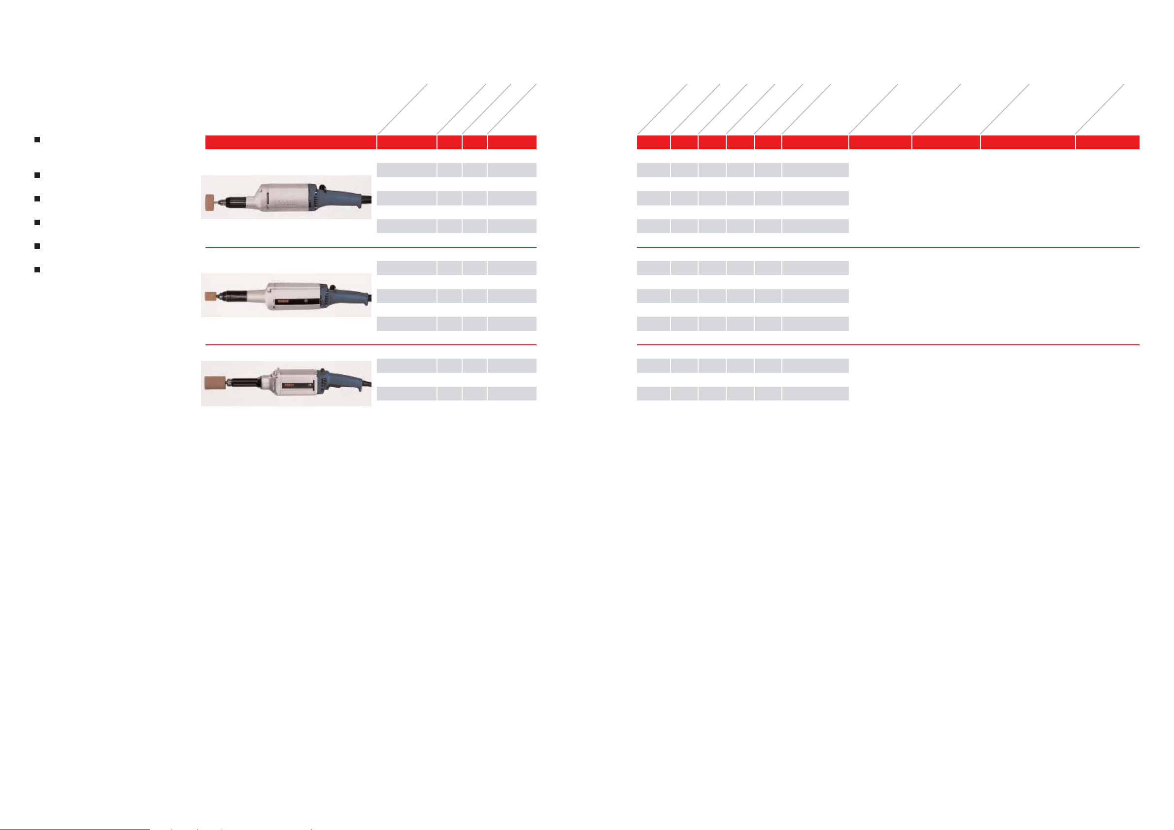
STRAIGHT GRINDERS.
The optimised straight grinders in
all power classes for the widest possible variety of applications
The ideal structural shape for ergonomic work
Constant speed, even at extremely
high loads
Efficient work with longest possible
service life
Robust motors with long service
lives and low maintenance costs
Extremely favourable weight-performance ratio
Order number
Voltage (V)
Frequency (Hz)
1 608 570 025
1 907 950 506
1 907 950 509
0 602 210 001 265 200 50
0 602 210 004 135 200 50
0 602 210 004 200 300 50
0 602 211 004 265 200 50
0 602 211 010 135 200 50
0 602 211 017 72 200 50
0 602 211 010 200 300 50
0 602 211 018 72 300 50
0 602 245 034 200 300 40
0 602 245 011 72 300 40
3100 600 440 1.6 2.5 6
3100 600 440 3.3 2.5 6
4700 900 630 3.3 2.5 6
Collet chuck
l 6 mm
Open-ended spanner SW 12
Open-ended spanner SW 15
Post handle,
offsett drive for
polishing heads with
low circumference
velocity
Toggle
HGS 65/5 0
2 608 570 009
1 607 950 511
1 607 950 505
12 000 950 700 2.8 4.3 8
12 000 950 700 5.5 4.3 8
12 000 950 700 10.0 4.3 8
18 000 1450 1050 5.5 4.3 8
18 000 1450 1050 15.2 4.3 8
Collet chuck
l 8 mm
Open-ended spanner SW 14
Open-ended spanner SW 22
Post handle,
central output dirve
Toggle
3 607 950 004
18 000 1800 1500 6.4 4.7 Spindle M 14
18 000 1800 1500 17.7 4.7 Spindle M 14
Open-ended spanner SW 27Post handle,
central output dirve
for grinding wheels
with internal thread
Toggle
Lever switch with
lock
for grinding points
40 to 50 mm in diameter
The machines come equipped with a special 4-m-long cable without plug.
HGS 77/50
HGS 85/40
Your specialist dealer can provide you with information on the complete set of quality accessories.
Page 13

24 25
No load speed
(rpm)
Nominal power
consumption (W)
Nominal power
Output (W)
Nominal current (A)
Weight without
cabel (kg)
Toolholding
fixture
Collet chuck (mm)
Switch
type
Remarks
Comes complete
with
Accessory
Part number
Admissible
grinding point-
l
(mm)
STRAIGHT GRINDERS.
The optimised straight grinders in
all power classes for the widest possible variety of applications
The ideal structural shape for ergonomic work
Constant speed, even at extremely
high loads
Efficient work with longest possible
service life
Robust motors with long service
lives and low maintenance costs
Extremely favourable weight-performance ratio
for grinding wheels
50 to 80 mm in diameter
The machines come equipped with a special 4-m-long cable without plug.
Order number
Voltage (V)
Frequency (Hz)
3 607 950 005
3 607 950 006
3 605 510 025
3 605 703 028
3 605 703 074
3 607 950 005
3 607 950 006
3 605 510 025
3 605 703 028
3 605 703 074
0 602 211 101 265 200 75 mm
l
0 602 211 107 135 200 45 m/s
0 602 211 116 72 200 circumference
velocity
0 602 211 134 200 300 50 mm
l
45 m/s
circumference
velocity
0 602 243 134 200 300 80 mm
l
45 m/s
circumference
velocity
12 000 950 700 2.8 4.7
12 000 950 700 5.5 4.7
12 000 950 700 10.0 4.7
18 000 1450 1050 5.5 4.7
Open-ended spanner SW 32
Pin sparrer
Protective guard
Mounting flange
Collet flange
Open-ended spannerSW 32
Pin sparrer
Protective guard
Mounting flange
Collet flange
The machine must
not be operated
without a protective
guard.
The machine must
not be operated
without a protective
guard.
Toggle
Lever with lock
Mounting flanges M 14
for grinding wheels
with bore-
l 20 mm
Mounting flanges M 14
for grinding wheels
with bore-
l 20 mm
HGS 77/75
3 607 950 005
3 607 950 006
3 605 510 025
3 605 703 028
3 605 703 074
10 700 1800 1500 6.4 5.4 Open-ended spanner SW 32
Pin sparrer
Protective guard
Mounting flange
Collet flange
The machine must
not be operated
without a protective
guard.
Lever with lockMounting flanges M 14
for grinding wheels
with bore-
l 20 mm
HGS 85/8 0
Your specialist dealer can provide you with information on the complete set of quality accessories.
3 607 950 005
3 607 950 006
3 605 510 019
3 605 703 028
3 605 703 074
0 602 212 101 265 200 100 mm
l
0 602 212 104 135 200 45 m/s
0 602 212 107 72 200 circumference
velocity
9000 950 700 2.8 5.1
9000 950 700 5.5 5.1
9000 950 700 10.1 5.1
Open-ended spanner SW 32
Pin sparrer
Protective guard
Mounting flange
Collet flange
The machine must
not be operated
without a protective
guard.
ToggleMounting flanges M 14
for grinding wheels
with bore-
l 20 mm
HGS 77/100
3 607 950 005
3 607 950 006
3 605 510 019
3 605 703 028
3 605 703 074
3 607 950 005
3 607 950 006
3 605 510 019
3 605 703 028
3 605 703 074
3 607 950 010
1 607 950 061
0 602 242 101 265 200 100 mm
l
0 602 242 104 265 200 45 m/s
0 602 242 107 72 200 circumference
velocity
0 602 242 134 200 300 100 mm
l
45 m/s
circumference
velocity
0 602 242 436 200 300 125 mm
l
45 m/s
circumference
velocity
8600 1200 1000 3.3 5.5
8600 1200 1000 3.3 5.5
8600 1200 1000 11.8 5.5
8600 1800 1500 6.4 5.5
6800 1800 1500 6.4 5.5
Open-ended spanner SW 32
Pin sparrer
Protective guard
Mounting flange
Collet flange
Open-ended spanner SW 32
Pin sparrer
Protective guard
Mounting flange
Collet flange
Open-ended spanner SW 32
Pin sparrer
The machine must
not be operated
without a protective
guard.
The machine must
not be operated
without a protective
guard.
The machine must
not be operated
without a protective
guard.
Lever with lock
Lever with lock
Toggle
Mounting flanges M 14
for grinding wheels
with bore-
l 20 mm
Mounting flanges M 14
for grinding wheels
with bore-
l 20 mm
Mounting flanges M 14
for grinding wheels
with bore-
l 20 mm
HGS 85/1 00
Page 14

26 27
Toolholding
fixture
Collet chuck (mm)
Switch
type
Remarks
Comes complete
with
Accessory
Part number
Weight without
cabel (kg)
Nominal current (A)
Nominal power
Output (W)
Nominal power
consumption (W)
No load speed
(rpm)
Admissible
grinding
wheels-
l
(mm)
Frequency (Hz)
Voltage (V)
Order number
STRAIGHT GRINDERS.
The optimised straight grinders in
all power classes for the widest possible variety of applications
The ideal structural shape for ergonomic work
Constant speed, even at extremely
high loads
Efficient work with longest possible
service life
Robust motors with long service
lives and low maintenance costs
Extremely favourable weight-performance ratio
for grinding wheels
125 to 180 mm in diameter
3 607 950 010
1 607 950 061
3 605 510 014
3 605 703 068
3 605 703 077
0 602 213 104 200 300 125 mm
l
45 m/s
circumference
velocity
6800 145 0 1050 5.5 5.2 Open-ended spanner SW 32
Pin spanner
Protective guard
Mounting flange
Collet flange
The machine must not
be operated without a
protective guard.
ToggleMounting flanges M 14
for grinding wheels
with bore-
l 20 mm
HGS 77/125
The machines come equipped with a special 4-m-long cable without plug. Your specialist dealer can provide you with information on the complete set of quality accessories.
3 607 950 010
1 607 950 061
3 605 510 018
3 605 703 068
3 605 703 077
3 607 950 010
1 607 950 061
3 605 510 018
3 605 703 068
3 605 703 077
0 602 240 104 135 200 150 mm
l
0 602 240 107 72 200 45 m/s
circumference
velocity
0 602 240 134 200 300 150 mm
l
45 m/s
circumference
velocity
5700 1950 1500 10.0 7.7
5700 1950 1500 18.0 7.7
5700 2900 2200 10.0 7.7
Open-ended spanner SW 32
Pin spanner
Protective guard
Mounting flange
Collet flange
Open-ended spanner SW 32
Pin spanner
Protective guard
Mounting flange
Collet flange
The machine must not
be operated without a
protective guard.
The machine must not
be operated without a
protective guard.
Lever with lock
Lever with lock
Mounting flanges M 14
for grinding wheels
with bore-
l 20 mm
Mounting flanges M 14
for grinding wheels
with bore-
l 20 mm
HGS 88/1 50
3 607 950 010
1 607 950 061
3 605 510 031
3 605 703 068
3 605 703 077
0 602 240 034 200 300 150 mm
l
0 602 240 035 200 300 80 m/s
circumference
velocity
10 200 2900 2200 10.0 7.7
10 200 2900 2200 10.0 7.7
Open-ended spanner SW 32
Pin spanner
Protective guard
Mounting flange
Collet flange
The machine must not
be operated without a
protective guard.
Lever with lock
Lever
without lock
Mounting flanges M 14
for grinding wheels
with bore-
l 20 mm
HGS 88/1 50
3 607 950 010
1 607 950 061
3 605 510 035
3 605 703 068
3 605 703 077
3 607 950 010
1 607 950 061
3 605 510 035
3 605 703 068
3 605 703 077
0 602 239 104 135 200 180 mm
l
0 602 239 107 72 200 45 m/s
circumference
velocity
0 602 239 134 200 300 180 mm
l
45 m/s
circumference
velocity
4800 1950 1500 10.0 7.9
4800 1950 1500 18.0 7.9
4800 2900 2200 10.0 7.9
Open-ended spanner SW 32
Pin spanner
Protective guard
Mounting flange
Collet flange
Open-ended spanner SW 32
Pin spanner
Protective guard
Mounting flange
Collet flange
The machine must not
be operated without a
protective guard.
The machine must not
be operated without a
protective guard.
Lever with lock
Lever with lock
Mounting flanges M 14
for grinding wheels
with bore-
l 20 mm
Mounting flanges M 14
for grinding wheels
with bore-
l 20 mm
HGS 88/1 80
Page 15

28 29
Accessory
Part number
Switch
type
Toolholding
fixture
chuck (mm)
Weight without
cabel (kg)
Nominal current (A)
Nominal power
Output (W)
Nominal power
consumption (W)
No load speed
(rpm)
Admissible grinding
wheels-
l (mm)
Frequency (Hz)
Voltage (V)
Order number
ANGLE GRINDERS.
The correct grinder/sander for
every application
Extremely robust and maintenancefriendly motors
Constant speeds throughout the
whole power range for top economy
and longest possible service lives
Robust angular gear with high
operational performance
1 607 950 052
1 602 025 031
1 603 345 043
2 605 703 014
0 602 324 301 265 200 125
0 602 324 304 135 200 125
0 602 324 307 72 200 125
4800 520 360 1.6 2.0
4800 520 360 3.2 2.0
4800 520 360 6.1 2.0
Pin-type wrench
Auxiliary handle
Pin-type wrench
Mounting flange
For fibre-sanding discs
with spindle locking.
SDS-clic available as
special accessory
Slide-
switch
Mounting flanges M 14
for grinding wheels
with bore-
l
22,3 mm
HWS 5265/125
Remarks
Comes complete
with
for grinding wheels
100 to 18 0 mm in diameter
1 605 510 155
1 607 950 052
2 607 950 511
1 602 025 022
1 603 345 043
0 602 326 104 200 300 125 9000 900 63 0 3.3 3.2 Protective guard
l 125 mm
Pin-type wrench
Open-ended spanner SW 17
Auxiliary handle
Pin-type wrench
For light grinding workToggleMounting flanges M 14
for grinding wheels
with bore-
l
22,3 mm
HWS 65/125
1 605 510 155
1 607 950 052
1 602 025 031
1 603 345 043
2 605 703 014
0 602 324 341 265 200 125
0 602 324 344 135 200 125
0 602 324 347 72 200 125
0 602 324 324 200 300 125
0 602 324 331 72 300 125
5800 520 360 1.6 2.2
5800 520 360 3.2 2.2
5800 520 360 6.1 2.2
7300 800 550 3.2 2.2
7300 800 550 8.7 2.2
Protective guard
l 125 mm
Pin-type wrench
Auxiliary handle
Pin-type wrench
Mounting flange
For light grinding work
For fan-type discs
Slideswitch
Mounting flanges M 14
for grinding wheels
with bore-
l
22,3 mm
HWS 5265/125
2 607 950 511
1 602 025 022
0 602 305 001 265 200 175
0 602 305 004 135 200 175
0 602 305 008 72 200 175
0 602 306 034 200 300 175
1750 950 700 2.8 4.4
1750 950 700 5.5 4.4
1750 950 700 10.0 4.4
1650 1450 1050 5.5 4.4
Open-ended spanner SW 17
Auxiliary handle
For polishing workToggleMounting flanges M 14
for grinding wheels
with bore-
l
22,3 mm
HWS 77/175
2 607 950 511
1 602 025 022
1 607 950 052
0 602 301 201 265 200 125
0 602 301 204 135 200 125
0 602 301 207 72 200 125
0 602 301 204 200 300 125
0 602 327 001 265 200 100
4100 600 440 1.6 3.0
4100 600 440 3.3 3.0
4100 600 440 5.9 3.0
6150 900 630 3.3 3.0
2550 600 410 1.6 3.0
Open-ended spanner SW 17
Auxiliary handle
Pin-type wrench
For fibre-sandingToggleMounting flanges M 14
for grinding wheels
with bore-
l
22,3 mm
HWS 65/125
2 607 950 511
1 602 025 022
1 607 950 061
2 605 703 014
1 603 345 043
0 602 305 010 42 200 125 1750 950 700 17.5 4.5 Open-ended spanner SW 17
Auxiliary handle
Pin-type wrench
Mounting flange
Pin-type wrench
For wet grindingToggleMounting flanges M 14
for grinding wheels
with bore-
l
22,3 mm
HWS 77/100 for wet grinding
1 605 510 176
2 605 703 014
1 603 345 043
1 607 950 061
2 607 950 511
1 602 025 022
0 602 304 001 265 200 180
0 602 304 004 135 200 180
0 602 304 009 72 200 180
0 602 304 034 200 300 180
0 602 304 010 72 300 180
5700 950 700 2.8 4.6
5700 950 700 5.5 4.6
5700 950 700 10.0 4.6
8600 1450 1050 5.5 4.6
8600 1450 1050 15.2 4.6
Protective guard
l 180 mm
Mounting flange
Pin-type wrench
Pin-type wrench
Open-ended spanner SW 17
Auxiliary handle
For medium-heavy
grinding work
ToggleMounting flanges M 14
for grinding wheels
with bore-
l
22,3 mm
HWS 77/180
The machines come equipped with a special 4-m-long cable without plug. Your specialist dealer can provide you with information on the complete set of quality accessories.
Page 16

30 31
Accessory
Part number
Comes complete
with
Switch
type
Toolholding
fixture
chuck (mm)
Weight without
cabel (kg)
Nominal current (A)
Nominal power
Output (W)
Nominal power
consumption (W)
No load speed
(rpm)
Admissible grinding
wheels-
l (mm)
Frequency (Hz)
Voltage (V)
Order number
ANGLE GRINDERS.
1 605 510 176
2 605 703 014
1 603 345 043
1 607 950 061
2 607 950 511
1 602 025 022
0 602 329 001 265 200 180
0 602 329 004 135 200 180
0 602 329 007 72 200 180
0 602 329 034 200 300 180
0 602 329 011 72 300 180
0 602 329 036 200 300 180
8500 1200 1000 3.3 5.6
8500 1200 1000 6.4 5.6
8500 1200 1000 11.8 5.6
8500 1800 1500 6.4 5.6
8500 1800 1500 17.7 5.6
8500 1800 1500 6.4 5.6
Protective guard
l 180 mm
Mounting flange
Round nut
Pin-type wrench
Open-ended spanner SW 17
Auxiliary handle
For medium-heavy
grinding work. SDS-clic
available as special
accessory.
Lever with lock
Toggle
Mounting flanges M 14
for grinding wheels
with bore-
l
2,3 mm
HWS 85/18 0
Remarks
for grinding wheels
180 to 23 0 mm in diameter
1 605 510 176
2 605 703 014
1 603 345 043
1 607 950 061
2 607 950 511
1 602 025 022
0 602 331 001 265 200 180
0 602 331 004 135 200 180
0 602 331 007 72 200 180
0 602 331 003 265 200 180
0 602 331 034 200 300 180
0 602 331 036 200 300 180
8500 1950 1500 5.0 6.5
8500 1950 1500 10.0 6.5
8500 1950 1500 18.0 6.5
8500 1950 1500 5.0 6.5
8500 2900 2200 10.0 6.5
8500 2900 2200 10.0 6.5
Protective guard
l 180 mm
Mounting flange
Round nut
Pin-type wrench
Open-ended spanner SW 17
Auxiliary handle
For medium-heavy
grinding work. SDS-clic
available as special
accessory.
Lever with lock
Toggle
Lever with lock
Toggle
Mounting flanges M 14
for grinding wheels
with bore-
l
2,3 mm
HWS 88/18 0
1 605 510 173
2 605 703 014
1 603 345 043
1 607 950 061
2 607 950 511
1 602 025 022
0 602 332 001 265 200 230
0 602 332 011 200 300 230
0 602 332 034 200 300 230
0 602 332 003 265 200 230
0 602 332 036 200 300 230
0 602 332 005 135 200 230
6600 1950 1500 5.0 7.0
6600 2900 2200 10.0 7.0
6600 2900 2200 10.0 7.0
6600 1950 1500 5.0 7.0
6600 2900 2200 10.0 7.0
6600 1950 1500 10.0 7.0
Protective guard
l 180 mm
Mounting flange
Round nut
Pin-type wrench
Open-ended spanner SW 17
Auxiliary handle
For medium-heavy
grinding work. SDS-clic
available as special
accessory.
Lever with lock
Toggle
Lever with lock
Mounting flanges M 14
for grinding wheels
with bore-
l
2,3 mm
HWS 88/230
The machines come equipped with a special 4-m-long cable without plug. Your specialist dealer can provide you with information on the complete set of quality accessories.
The correct grinder/sander for
every application
Extremely robust and maintenancefriendly motors
Constant speeds throughout the
whole power range for top economy
and longest possible service lives
Robust angular gear with high
operational performance
Page 17

32 33
Accessory
Part number
Comes complete
with
Remarks
Switch
type
Toolholding
fixture
chuck (mm)
Weight without
cabel (kg)
Nominal current (A)
Nominal power
Output (W)
Nominal power
consumption (W)
No load speed
(rpm)
Admissible grinding
wheels-
l (mm)
Frequency (Hz)
Voltage (V)
Order number
ANGLE GRINDERS
1 605 510 173
2 605 703 014
1 603 345 043
1 607 950 061
2 607 950 511
1 602 025 022
0 602 334 101 265 200 230
0 602 334 107 72 200 230
0 602 334 134 200 300 230
0 602 334 136 200 300 230
6600 2500 2000 6.7 8.5
6600 2500 2000 24.7 8.5
6600 3800 3100 13.2 8.5
6600 3800 3100 13.2 8.5
Protective guard
l 230 mm
Mounting flange
Round nut
Pin-type wrench
Open-ended spanner SW 17
Auxiliary handle
For heavy grinding work.
SDS-click available as
special accessory.
Lever with lock
Lever with lock
Toggle
Mounting flanges M 14
for grinding wheels
with bore-
l
22,3 mm
HWS 810/23 0
for grinding wheels
230 to 300 mm in diameter
1 605 510 212
2 605 703 011
1 603 345 043
2 605 703 022
1 907 950 007
1 607 950 061
2 607 950 511
1 602 025 022
0 602 335 001 265 200 300
0 602 335 004 135 200 300
0 602 335 007 72 200 300
0 602 335 034 200 300 300
0 602 335 036 200 300 300
4700 2500 2000 6.7 10.0
4700 2500 2000 13.2 10.0
4700 2500 2000 24.7 10.0
5100 3800 3100 13.2 10.0
5100 3800 3100 13.2 10.0
Protective guard
l 300 mm
Mounting flange
Round nut
Mounting flange
Internal hexagon key
Pin-type wrench
Open-ended spanner SW 17
Auxiliary handle
For cutting work.
Lever with lock
Lever with lock
Toggle
Mounting flanges M 14
for grinding wheels
with bore-
l
22,3 mm
HWS 810/3 00
The machines come equipped with a special 4-m-long cable without plug. Your specialist dealer can provide you with information on the complete set of quality accessories.
The correct grinder/sander for
every application
Extremely robust and maintenancefriendly motors
Constant speeds throughout the
whole power range for top economy
and longest possible service lives
Robust angular gear with high
operational performance
Page 18

35
Accessory
Part number
Comes complete
with
Remarks
Switch
type
Toolholding
fixture
Collet chuck (mm)
Weight without
cabel (kg)
Nominal current (A)
Nominal power
Output (W)
Nominal power
consumption (W)
No load speed
(rpm)
Admissible grinding
wheels-
l (mm)
Frequency (Hz)
Order number
Voltage (V)
DI SC SAN DE R S AN D RAN DO M OR B IT SAN DE R S.
disc sanders and random orbit
sanders for sanding discs with
180 mm diameter
2 607 950 511
1 602 025 022
2 912 521 237
2 916 680 011
2 601 329 036
0 602 373 004 135 200 180
0 602 373 004 200 300 180
3600 850 580 2.2 3.7
5400 1300 900 4.5 3.7
For fibre-sanding discsToggleThreaded mounting
M 14
HTS 75/180
Open-ended spanner SW 17
Auxiliary handle
Ringscrew
Spring
Gloves
1 907 950 513
1 907 950 511
1 602 025 022
2 601 329 036
0 602 370 101 265 200 180
0 602 370 104 135 200 180
0 602 370 107 72 200 180
6000 1000 800 3.4 4.7
6000 1000 800 6.0 4.7
6000 1000 800 12.8 4.7
For fibre-sanding discsToggleThreaded mounting
M 14
HTS 86/180
Open-ended spanner SW 24
Open-ended spanner SW 19
Auxiliary handle
Gloves
2 602 025 067
2 605 411 046
2 605 702 009
1 907 950 007
0 602 370 301 265 200 150
0 602 370 304 135 200 150
0 602 370 307 72 200 150
0 602 370 311 72 300 150
0 602 370 334 200 300 150
5800 520 360 1.6 2.7
5800 520 360 3.2 2.7
5800 520 360 6.1 2.7
7300 800 550 6.1 2.7
7300 800 550 3.2 2.7
Slide switchFastener
HEX 526 5/15 0
Auxiliary Handle
Dust bag
Screw-on connector
Allen key
The machines come equipped with a special 4-m-long cable without plug. Your specialist dealer can provide you with information on the complete set of quality accessories.
34
The correct sander for all surfaces
Best sanding results, even on large
surfaces
Robust motors with an extremely
long service life
Small random orbit sander with
very high performance
Page 19

1 603 345 004
1 603 340 031
1 600 501 006
0 602
226 ...
...201/ ...204/ ...207
3736
SELECTION GUIDE FOR GRINDERS.
ACCESSORIES FOR ANGLE GRINDERS.
ACCESSORIES FOR STRAIGHT GRINDERS.
The table shows the relationship between the permissible diameter of the grinding wheel
and the speed.
speed 60000
rpm
50000
40000
30000
20000
15 000
12000
10000
8000
5000
4000
3000
2000
1500
1000
disc-ø mm
10 15 20 30 40 50 60 80 100 120 150 178 230 300
100 m/s
60 m/s
20 m/s
15 m/s
10 m/s
5 m/s
80 m/s
45 m/s
25 m/s
Admissible working speed
Observe the following with grinding stones: Permissible speeds
(rpm) depend on abrasive wheel
diameter and length, as well as
shank diameter and clamping
length as per DIN 69170.
0 602 225 ...
...101/ ...104/ ...107/
... 204/ ...211
0 602
236 ...
...001/ ...007
0 602
237
004
0 602
233 ...
...201/ ...204/ ...207/
...304
0 602
227
...
...204/ ...211
0 602
228
...
...201/ ...204/ ...207/
...211
0 602
229
...
...101/ ...104
0 602
228
...
...361/ ...361/ ...371/
...374/ ...377
0 602
238 ...
...101/ ...104/ ...107/
...134/ ...111
0 602
207
...
...001/ ...008
0 602
208
001
0 602
209 ...
...101/ ...104/ ...107/
...134/ ...111
0 602
210 ...
...001/ ...004
0 602
211 ...
...004/ ...010/ ...017/
...018
3 mm1 608 570 0312 608 570 077 – –
1/8’’ –2 6 0 8 570 078 – –
4 mm1 608 570 033 – – –
6 mm1 608 570 0372 608 570 079 2 608 570 118 –
1/4’’ –2 6 0 8 570 080 – 2 608 570 014
8 mm –2 6 0 8 570 081 2 608 570 0162 608 570 009
10 mm – – – 2 608 570 017
Collets-ø
0 602 221...
and 243 ...
0 602 212 ...
and 242 ...
0 602 213 ...
0 602 240 ...
0 602 240 ...
0 602 239...
45 and 80 m/s 45 and 80 m/s 45 m/s 45 m/s 80 m/s 45 m/s
up to 80 mm ø up to 1 00 mm ø up to 125 mm ø up to 150 mm ø up to 150 mm ø up to 1 8 0 mm ø
Wheel guards 3 605 510 025 3 6 05 510 03 0 3 6 05 510 031 3 605 510 018 3 6 05 510 017 3 605 510 016
Mounting flange 3 605 703 028 3 605 703 028 3 605 703 068 3 605 703 068 3 605 703 068 3 605 703 068
Collet flange 3 605 703 074 3 605 703 074 3 605 703 077 3 605 703 077 3 605 703 070 3 605 703 077
admissible
grinding point
width (mm)
20/25 20/25 20/25 20/25 20/25 20
Accessories for conical grinding wheels
Spindle extension
Auxiliary handle
Order number
Product type for model
0 602 ...
Length in mm
3 606 120 031 ... 238 101 – 234 15 0
3 606 120 032 ... 238 101 – 234 3 00
3 602 025 008 ... 225 ... 4 6
Protective guard
Order number
Working-ø (mm)
1 605 510 110 180
Flange for straight grinding wheels
1 605 703 028
Flange for tappered grinding wheels
Locking nut
SDS quick clamping flange
Page 20

3938
Order number
Dimensions mm
DI ME NS IO NAL DRAWI N GS: STRAI G HT G R I N DE R S.
0 602 225 101
0 602 225 104
0 602 225 107
0 602 225 204
0 602 225 211
0 602 233 201
0 602 233 204
0 602 233 207
0 602 233 304
0 602 226 201
0 602 226 204
0 602 226 207
0 602 227 204
0 602 227 211
0 602 228 201
0 602 228 204
0 602 228 207
0 602 228 211
0 602 229 101
0 602 229 104
Order number
Dimensions mm
DI ME NS IO NAL DRAWI N GS: STRAI G HT G R I N DE R S.
0 602 228 361
0 602 228 364
0 602 228 371
0 602 228 374
0 602 228 377
0 602 238 101
0 602 238 104
0 602 238 107
0 602 238 111
0 602 238 134
0 602 207 001
0 602 207 004
0 602 207 008
0 602 208 001
0 602 209 101
0 602 209 104
0 602 209 107
0 602 209 111
0 602 209 134
Page 21

4140
Order number
Dimensions mm
DI ME NS IO NAL DRAWI N GS: STRAI G HT G R I N DE R S.
Order number
Dimensions mm
DI ME NS IO NAL DRAWI N GS: STRAI G HT G R I N DE R S.
0 602 212 101
0 602 212 104
0 602 212 107
0 602 242 101
0 602 242 104
0 602 242 107
0 602 242 134
0 602 242 436
0 602 213 104
0 602 240 034
0 602 240 035
0 602 240 104
0 602 240 107
0 602 240 134
0 602 239 104
0 602 239 107
0 602 239 134
0 602 210 001
0 602 210 004
0 602 211 004
0 602 211 010
0 602 211 017
0 602 211 018
0 602 245 011
0 602 245 034
0 602 211 101
0 602 211 107
0 602 211 116
0 602 211 134
0 602 243 134
Page 22

4342
Order number
Dimensions mm
DI ME NS IO NAL DRAWI N GS: AN G LE G R I N D E RS.
Order number
Dimensions mm
DI ME NS IO NAL DRAWI N GS: AN G LE G R I N D E RS.
0 602 329 001
0 602 329 004
0 602 329 007
0 602 329 011
0 602 329 034
0 602 329 036
0 602 331 001
0 602 331 003
0 602 331 004
0 602 331 007
0 602 331 034
0 602 331 036
0 602 332 001
0 602 332 003
0 602 332 004
0 602 332 005
0 602 332 007
0 602 332 011
0 602 332 034
0 602 332 036
0 602 334 101
0 602 334 107
0 602 334 134
0 602 334 136
0 602 335 001
0 602 335 004
0 602 335 007
0 602 335 034
0 602 335 036
0 602 324 301
0 602 324 304
0 602 324 307
0 602 324 341
0 602 324 344
0 602 324 347
0 602 324 324
0 602 324 331
0 602 301 201
0 602 301 204
0 602 301 207
0 602 301 104
0 602 327 001
0 602 305 010
0 602 304 001
0 602 304 004
0 602 304 009
0 602 304 010
0 602 304 034
0 602 305 001
0 602 305 004
0 602 305 008
0 602 306 034
M14:11mm deep
for water hose with 10 mm
l
M14:11mm deep
M14:
11mm deep
Page 23

44
SCR EWDR IVE RS
TAPPERS
Order number
Dimensions mm
DI ME NS IO NAL DRAWI N GS: D IS C SAN D E RS
AN D RAN DO M OR B IT SAN DE R S.
0 602 370 101
0 602 370 104
0 602 370 107
0 602 373 004
0 602 370 301
0 602 370 304
0 602 370 307
0 602 370 311
0 602 370 334
Page 24

4746
0,1 0,5 1 5 10 50 100 500 1000
Torque for hard screwdriving application as per ISO 5393 (Nm)
Hardness
class per
DIN 267
8.8 10.9
M 2.5 0.7 1.0
M 3 1.2 1.7
M 4 2.9 4
M 5 5.5 8
M 6 9.7 13.6
M 8 23 33
M 10 47 65
M 12 80 113
M 14 130 180
M 16 196 275
M 18 270 3 8 0
M 20 385 540
M 22 510 715
M 24 650 910
M 27 960 1345
M 30 1300 1830
Tightening
torque
Guideline values for maximum
bolt/screw tightening torques in
Nm. Assumed friction below head
m
ges.
= 0.12, calculated from the
stressed cross sections: yield point
usage 90 %. Valid for shaft screws
with standard metric thread as per
DIN 13, BL 13; heads as per
DIN 931, 933.
When you select a screwdriver,you
must consider not only the required torque – as a function of
the pretensioning force required
from the bolted connection – but
also the torque accuracy as a function of the bolting event. This
information has been compiled in
tables 1 and 2 in order to facilitate
the selection from among the
various bolting systems. The fixed
torque values provided apply to
“hard”bolted connections. The
maximum values are lower for
“soft”bolted connections (e.g.
spring washers, rubber washers,
etc.)
Order number
0 602 485 1..
0 602 488 1..
0 602 486 2..
0 602 489 0..
0 602 487 0..
0 602 442 0..
0 602 443 0..
0 602 440 0..
0 602 433 1..
0 602 438 0..
0 602 435 0..
0 602 439 0..
Screwdrivers with adjustable cut-off clutch
For screw connections with high torque accuracy
Torque upper range limited by reaction torques
Further advantages: low noise,low wear, long service life,
the user has no influence on the torque
Impact Wrenches
For large screw / bolt diameters with high torque
Virtually free of reaction torque,therefore no upward limitation
Torque is a decisive parameter for
controlling the pretension force
applied. The table provides an overview of the recommended torques
for common bolt and nut sizes.The
recommended maximum torques
apply to untreated,oil-lubricated
screws (coefficient of friction =
0.125). The torques correspond to
approx.62% of the yield point.
Torque accuracy
with automatic
shut-off
Torque accuracy
with overload
disengaging clutch
Torque accuracy
with percussion
mechanism
Torque Torque Torque Torque Torque
Rotation
Rotation
Rotation
Rotation
Rotation
Rotation
up to
approx.
30°
up to
approx.
60°
over 60°
angle of
rotation
not
definable
very good good to very good satisfactory –
depending upon
the degree of
accuracy required
somewhat
unsatisfactory
satisfactory –provided only a low
level of accuracy
is required
satisfactory
satisfactory
good to very good good to
satisfactory
satisfactory
satisfactory
good
good – provided
cut-out function
is still operative
good – provided
cut-out function
is still operative
good – provided
cut-out function
is still operative
good – provided
cut-out function
is still operative
goodgood – provided
that the function
is still operative
Bolting event Angle of
rotation
to M
d
max.
Torque accuracy depending
on screwdriver system and
screwdriving type
The torque that can be achieved for
a screw connection depends on the
type of screwdriving / bolting situation. To achieve a balanced basis for
assessment, all data on screwdrivers
is based on unbending,or “hard”
screw connections (30° angle of
rotation).In the case of flexible or
“soft”screw connections,achievable
values are,in part, considerably
belowthe nominal values. Furthermore , torq ue v a r i a n ce increases. Due
to the wide varie ty of possibilities,
specifications with absolute values
are not possible. If in doubt, use a
trial and error system. The table
offers an overview of the advantages
and achievable torque accuracy of
the individual screwdriver s ystems
with various characteristic screwdriving applications.
Torque
SEL EC TI ON GUI D E FO R SC REWD R IVER S.
Page 25

Accessory part
number
Comes complete
with
Toolholding fixture
Hex. = hexagon
Remarks
Weight without
cabel (kg)
Nominal current (A)
Nominal power
output (W)
Nominal capacity
Output (W)
No load speed
(rpm)
Torque (Nm) for hard
screwdriving application
as per ISO 5393
Max.
thread size
Frequency (Hz)
Voltage (V)
Order number
CUT-O UT SC R EWD RIVER S.
1 607 950 0370 602 485 101 265 200 M 4
0 602 485 104 135 200 M 4
0 602 485 118 42 300 M 4
0.8–2.5 840 80 40 0.2 0.8 1/4
HH Hex.
0.8–2.5 840 80 40 0.5 0.8 1/4
HH Hex.
0.9–3.0 1260 125 65 2.4 0.8 1/4
HH Hex.
Gib-head key
for torque adjustment
Handle grip
with ON/OF F and
reverse switch
HS R 44-A
with adjustable cut-out
clutch for screws from
M4 to M10
The machines come equipped with a special 4-m-long cable without plug.
1 607 950 037
0 602 488 101 265 200 M 6
0 602 488 104 135 200 M 6
0 602 488 107 72 200 M 6
0 602 488 104 200 300 M 6
0 602 488 118 42 300 M 6
3–6 840 170 85 0.5 1.1 1/4
HH Hex.
3–6 840 170 85 1.0 1.0 1/4
HH Hex.
3–6 840 170 85 1.8 1.0 1/4
HH Hex.
3.2–6.5 1260 265 135 1.0 1.0 1/4
HH Hex.
3.2–6.5 1260 265 135 5.0 1.0 1/4
HH Hex.
Gib-head key
for torque adjustment
Handle grip
with ON/OF F and
reverse switch
HS R 48-A
1 607 950 037
0 602 486 201 265 200 M 6
0 602 486 204 135 200 M 6
0 602 486 204 200 300 M 8
3.5–12 590 260 140 0.9 2.1 1/4
HH Hex.
3.5–12 590 260 140 1.7 1.7 1/4
HH Hex.
4–13 900 400 220 1.7 1.7 1/4
HH Hex.
Gib-head key
for torque adjustment
Middle grip
with ON/OF F and
reverse switch
HS R 55-A
1 607 950 037
0 602 489 001 265 200 M 8
0 602 489 004 135 200 M 8
0 602 489 007 72 200 M 8
0 602 489 004 200 300 M 8
5–17 690 400 270 1.6 2.3 1/4
HH Hex.
5–17 690 400 270 3.3 2.3 1/4
HH Hex.
5–17 690 400 270 6.1 2.3 1/4
HH Hex.
6–20 1040 600 400 3.3 2.3 1/4
HH Hex.
Gib-head key
for torque adjustment
Pistol grip
with ON/OF F and
reverse switch
HS R 57-A
1 607 950 037
0 602 487 001 265 200 M 10
0 602 487 004 135 200 M 10
0 602 487 007 72 200 M 10
9–24 780 350 200 1.0 2.8 1/4
HH Hex.
9–24 780 350 200 2.0 2.8 1/4
HH Hex.
9–24 780 350 200 3.0 2.8 1/4
HH Hex.
Gib-head key
for torque adjustment
Middle grip
with ON/OF F and
reverse switch
HS R 64-A
48 49
Your specialist dealer can provide you with information on the complete set of quality accessories.
Page 26

5150
Comes complete
with
Accessory part
number
Toolholder Drive
Hex. = hexagon
Sq. = external square
Weight without
cabel (kg)
Nominal current (A)
Nominal power
output (W)
Nominal capacity
Output (W)
No load speed
(rpm)
Torque (Nm) for hard
screwdriving application
as per ISO 5393
Max.
thread size
Frequency (Hz)
Voltage (V)
Order number
IMPACT WRENCHES.
0 602 442 001 265 200 M 10
0 602 442 004 135 200 M 10
0 602 442 007 72 200 M 10
0 602 443 004 200 300 M 10
30 1650 170 85 0.5 1.1 1/4
HH Hex.
30 1650 170 85 1.0 1.1 1/4
HH Hex.
30 1650 170 85 1.8 1.1 1/4
HH Hex.
30 1780 265 135 1.0 1.1 1/4
HH Hex.
Handle grip with
ON/OF F and
reverse switch
HSS 48
Remarks
impact wrenches for
screws from M6 to M30
0 602 440 001 265 200 M 12
0 602 440 004 135 200 M 12
80 1410 260 140 0.9 2.4 1/2HH Sq. with spring pin
80 1410 260 140 1.7 2.4 1/2
HH Sq. with spring pin
Handle grip with
ON/OF F and
reverse switch
HSS 55
0 602 435 001 265 200 M 22
0 602 435 004 135 200 M 22
0 602 435 008 72 200 M 22
350 800 850 580 2.2 5.6 3/4HH Sq.
350 800 850 580 4.5 5.6 3/4
HH Sq.
350 800 850 580 8.5 5.6 3/4
HH Sq.
Palm grip with
ON/OF F and
reverse switch
Auxiliary handle 1 602 025 03 0
HSS 75
0 602 433 101 265 200 M 16
0 602 433 104 135 200 M 16
0 602 433 107 72 200 M 16
0 602 438 004 200 300 M 16
190 1100 360 220 1.0 3.0 1/2
HH Sq. without spring pin
190 1100 360 220 2.0 3.0 1/2
HH Sq. without spring pin
190 1100 360 220 3.7 3.0 1/2
HH Sq. without spring pin
190 1100 550 340 2.0 3.0 1/2
HH Sq. without spring pin
Centre grip with
ON/OF F and
reverse switch
HSS 64
0 602 439 001 265 200 M 30
0 602 439 004 135 200 M 3 0
0 602 439 007 72 200 M 30
1000 600 950 700 2.8 8.6 1HH Sq.
1000 600 950 700 5.5 8.6 1
HH Sq.
1000 600 950 700 10.0 8.6 1
HH Sq.
Two handled grip
with ON/OF F and
reverse switch
HSS 77
The machines come equipped with a special 4-m-long cable without plug. Your specialist dealer can provide you with information on the complete set of quality accessories.
Page 27

Accessory part
number
Comes
complete with
Remarks
Toolholding
fixture
Weight without
cabel (kg)
Nominal current (A)
Nominal power
output (W)
Nominal power
consumption (W)
Reverse
No load speed
(rpm) forward
Nominal power
consumption [W]
Spacebolt
l (mm)
Working range
thread
l
(mm)
Frequency (Hz)
Voltage (V)
Order number
TAPPERS.
0 602 463 101 265 200 8 6
0 602 463 104 135 200 8 6
0 602 463 107 72 200 8 6
3–10 380 750 260 150 0.9 2.3 Cone B 12 DIN 238
3–10 380 750 260 150 1.7 2.3 Cone B 12 DIN 238
3–10 380 750 260 150 3.2 2.3 Cone B 12 DIN 238
HGR 55/1 0
tappers for threads up
to 8 mm in diameter
3 608 573 000
3 603 111 004
3 603 111 005
3 603 111 003
2 607 950 012
Two-jaw drill chuck
Fastening key
for 3.0 mm high
for 3.3 mm high
for 3.6 mm high
Spare key
52 53
The machines come equipped with a special 4-m-long cable without plug. Your specialist dealer can provide you with information on the complete set of quality accessories.
Page 28

0 602 433 ...
0 602 442 ...
0 602 489 ...
0 602 486 ...
0 602 488 ...
0 602 485 ...
55
Order number
Dimensions mm
DI ME NS IO NAL DRAWI N GS:
CUT-OUT SCR EWDRIVERS.
0 602 485 101
0 602 485 104
0 602 485 118
0 602 488 101
0 602 488 104
0 602 488 107
0 602 488 118
0 602 486 201
0 602 486 204
0 602 489 001
0 602 489 004
0 602 489 007
0 602 487 001
0 602 487 004
0 602 487 007
ACCESSORI ES FOR SHUT-OFF SCREWDRIVER.
SP EC IAL ACCESS OR IES FO R S CR EWD R IVER S.
Order number
Packing unit
3 604 682 001
••
1
3 604 682 000
••
1
Hanging hook
Order number
Packing unit
3 604 682 001 1
2 910 021 118
•••
1
1 606 455 012
•
1
0 602 440 ...
0 602 443 ...
Loop hanger
Cylinder screws for fastening
Quick-change collet chuck 7/16
HH
Your specialist dealer can provide you with information on the complete set of quality accessories.
54
Page 29

Order number
M14; 11 deep
M24x2 13 deep
Order number
Dimensions mm
DI ME NS IO NAL DRAWIN GS: I M PACT WRE NCH ES.
0 602 433 101
0 602 433 104
0 602 433 107
0 602 438 004
0 602 435 001
0 602 435 004
0 602 435 008
0 602 439 001
0 602 439 004
0 602 439 007
56
Order number
Dimensions mm
Dimensions mm
DI ME NS IO NAL DRAWIN GS: I M PACT WRE NCH ES.
DI ME NS IO NAL DRAWI N GS: AN G LE WR E N CH ES.
0 602 442 001
0 602 442 004
0 602 442 007
0 602 443 004
0 602 440 001
0 602 440 004
0 602 463 101
0 602 463 104
0 602 463 107
57
Cone B12 DIN 238
with transverse key
Two-jaw drill chuck
Page 30

5958
ACCESSORIES
Page 31

6160
Order number
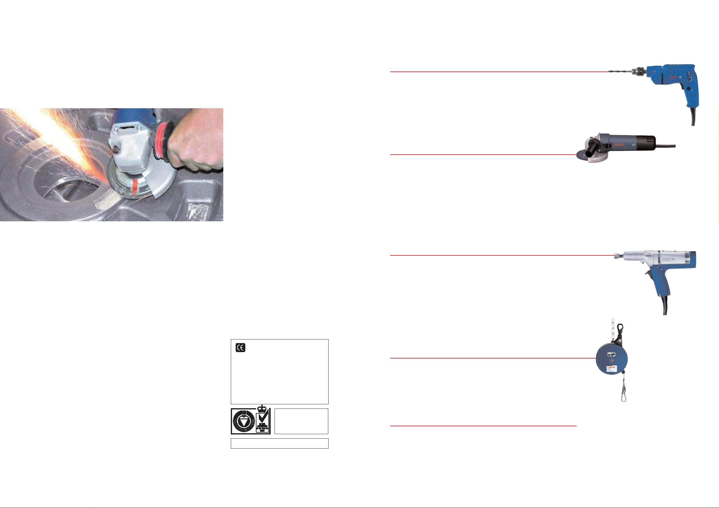
BAL ANC ER .
Robust metal safety hanger including spring hook
Bowden cable with high-quality
distributor valve and safety coupling for uniform pulling out behaviour
Spring fracture safety device
balancers with a load burden
greater than 3 kg
Cable change possible without
disassembly of the spring drum
Simple change of the weight class
through modular structure
Balancer
0 607 950 920
Balancer
for loads
from 0.3 to 17 kg
0 607 950 921
0 607 950 922
0 607 950 923
0 607 950 931
0 607 950 937
Balancer
0 607 950 924
0 607 950 925
0 607 950 926
Balancer
0 607 950 927
0 607 950 928
Balancer
Remarks
Weight
(kg)
Max. lift
(mm)
Load
max. (kg)
Load
min. (kg)
0.3 1.2 1200 0.5 Spring balancer with adjustable load range
Your specialist dealer can provide you with information on the complete set of quality accessories.
0.6 1 2000 0.7
1 2 2000 0.7
2 3 2000 0.8
0.5 2 2000 0.7
1.5 3 2000 0.8
Spring balancer with adjustable load range
Balancer with adjustable load range with lock
3 5 2000 3
6 8 2000 3.2
8 10 2000 3.4
Spring balancer with adjustable load range
9 14 2000 3.4
13 17 2000 3.6
Spring balancer with adjustable load range
Page 32

6362
HIGH-FREQUENCY
TECH NOLOGY
PLU G CO N N E CTI O N S, LEADS.
Connector plug
Coupling socket
Wall socket
Order number
Voltage (V)
Load capacity (A)
Packing unit
1 614 482 048 50 – 300 16 1
1 614 482 049 50 – 300 32 1
1 614 482 050 to 50 32 1
1 614 484 010 50 – 300 16 1
1 614 484 011 50 – 300 32 1
1 614 484 012 to 50 32 1
1 614 485 024 5 0 – 3 00 16 1
1 614 485 025 5 0 – 3 00 32 1
1 614 485 026 to 50 32 1
CEE plugged connections DI N 49 4 62/63 and DI N 49
465 for frequencies from 100 to 300 Hz (green housing)
4-core cable
(length 50 m)
3-core cable
(length 50 m) for 42 V operating voltage
working lenght 4 m (spiral line)
working lenght 6 m (spiral line)
Order number
Material number
Lead cross-
section (mm
2
)
Outer-Ø (mm)
3 604 422 003* 6 254 812 403 0.75 18
3 604 422 077* 3 6 0 4 422 023 1.50 11
3 604 422 050* 3 604 422 024 2.50 13
3 604 462 002 0.75 8
3 604 462 003 0.75 8
3 604 422 004 6 254 811 303 0.75 17
*unpacked
Electrical leads
Frequency converters can be obtained from: EM E GmbH · Postfach 0306 · D-78257 Ettlingen · Telephone 0 7243/32 0 6 0 6 · Fax 072 43/32 0 6 11 or 32 0612
Please consult your stockist for information on the complete range of quality accessories.
Page 33

6564
A real concept:
High-frequency Tools
How a good idea was consistently
further developed: The designation
’high-frequency tools’came to be
known through the market launch
of the tools and was given to those
powerful high-frequency tools with
asynchronous motors,operated
with three-phase current at an
increased frequency of 200 or 300
Hz. In a physical sense,there is no
real connection between these
tools and genuine high-frequency
technology,but they still came to
be known under this name.
The operating
frequency determines
the performance
In hand tools, rotar y current at
increased frequency of 200 or
300 Hz combines high electrical
performance with minimal motor
weight. As the frequency of the
rotary current increases, there is
a proportional increase in motor
speed and thus in the performance of asynchronic motors.
This is limited by the maximum
admissible circumference velocity
(operating rotational speed) of
the tools.An optimum performance/weight ratio is achieved
by high-frequency tools operating
at a frequency of 200 to 300 Hz
(Fig. 1). Large differences between motor rotational speed and
operating rotational speed
require larger gears. This means
that weight savings from the
rotary current drive are negated
by the increased weight from the
stepdown gearing.
High-frequency installations using
exclusively grinders should be
operated at 300 Hz. Using rotar y
current at increased frequency
optimally fulfils the demand for
light yet high-performance hand
tools.
Fig. 1 The graph shows the dependence of motor and gearing weight on frequency at constant motor performance and rated rotational speed.
300 Hz yields an optimum performance/weight ratio.
Weight (kg)
Total weight
Gear weight
Motor weight
Frequency (Hz)
0 100 200 300 400 500
ROBUST TECHNOLOGY FOR LONG-TERM
HEAVY-DUTY USE.
A high-frequency motor is a three-phase current motor with a short-circuit rotor. Its stator and
rotor consist of a laminated sheet-metal bundle. If the stator winding of the motor is connected
to the three-phase current supply, a magnetic field is created (rotary field), which runs through
the motor due the arrangement of the winding and which is dependent on number of pole pairs
and the frequency.
Rotor
Stator
Fan
Housing
Page 34

6766
An operating frequency of 300 Hz
is to be recommended for a highfrequency electric tool installation. The higher motor rotational
speed at 300 Hz is particularly
advantageous at today's circumference velocities for grinders.
The increased motor rotational
speed results in higher machine
performance without an increase
in weight. In so far as possible,
135 V current should be selected
for 200 Hz and 200 V for 300 Hz,
regardless of country.
The secondary power output of
the frequency converter or its size
is calculated as follows: The hig hfrequency electric tools to be used
are grouped according to motor
size and number so that their
rated current consumption can
be added together. Multiplying
the sum of the rated cur rent
values by the operating voltage
and the factor ö3 results in a
calculation for the entire apparent
power consumption for the tools.
The formula is:
S =
ö
3 · U · I = 1.73 · U · I
Once the apparent power value
has been calculated in this way,
it must still be multiplied by the
simultaneity factor G in order to
obtain the secondary power output of the converter.The simultaneity factor G takes into account
the degree of use of all of the
tools–since the tools are generally not all used at the same time.
E LE CTRI CAL OP E RATI N G VALUE S.
For the simultaneity factor G, we
have the following experiential
values:
automobile body
manufacture 0.45
motor manufacture 0.30
appliance manufacture 0.40
tool and form manufacture 0.25
steel manufacture 0.50
foundry work 0.60
In planning for a high-frequency
electric tool installation, you must
always take into account the need
for a certain amount of reser ve
power in the frequency converter.
Particularly for small installations,
you must bear in mind that the
power output must be at least
twice the rated power consumption of the most powerful highfrequency electric tool to be
connected.This ensures that the
tools will start without trouble.
In the event of short-term overload, the voltage drop at the
frequency converter will not be
too large.
A magnetic field forms in a threephase current motor, which circulates through the motor. This is
called a rotary field and is dependent on the number of pole pairs
and frequency. When the smallest
possible number of pole pairs is
used, at a frequency of 50 Hz, for
example, a rotar y field or rotor
speed of 3000 rpm results; at a frequency of 200 Hz: 12000 r pm and
at 300 Hz: 18000 rpm.
Due to the short distance between
bearings and the stationary stator
coil, the motor is both mechanically and electrically very reliable.
It is distinguished by steady, lowvibration operation. Speed drop
is only approx.5% at rated load,
and peak performance is around
21/2 times the rated performance.
Short-term overloads are possible
as long as they do not result in the
admissible coil temperature being
exceeded.Since the objective in
hand tools is to make them as
light as possible with the highest
possible performance, Bosch has
decided in favour of“dust protection with direct cooling" for its
high-frequency motors (Fig. 2).
This combines the advantages of
both encapsulated and open construction. The flow of cooling air
ensures good heat dissipation; at
the same time, dust and dirt are
prevented from penetrating into
the rotating system.
The design concept underlying
Bosch high-frequency electric
tools offers the user the following
advantages:
Optimum performance in
a light-weight tool
During extended operation, Bosch
high-frequency elect ric tools
achieve a performance level of
up to 400 watts per kilogram
machine weight. Shor t-term peak
performance levels reach 2 1/2
times normal operating perfor
mance output.These high reserves
mean a decisive improvement in
work performance.
Constant rotational speed
under load
The speed drop for Bosch highfrequency electric tools is only
3 – 5% at rated load (Fig. 2).
This ensures that recommended
average speeds can be used to
full advantage during grinding
and drilling. The constant average
speed means that the tools can
be employed more efficiently and
RELIABLE THREE-PHASE CURRENT MOTORS WITH
A LONG SERVICE LIFE.
Fig. 2 Output and rotational speed cur ve as a function of load moment
Sample calculation for a
high-frequency electric
tool installation
A foundry wishes to introduce
3 high-frequency 0 602 332 034
angle grinders with 230 mm
diameter cutting discs and 3 highfrequency 0 602 242 134 straight
grinders with 100 mm diameter
grinding discs.
Calculation:
(Refer to pages 24 – 25 and 30– 31
for current and voltage values)
3 grinders,
motor size 88 3· 10 A = 30.0A
3 girnders,
motor size 85 3· 6.4 A = 19.2 A
Total: 49.2A
This yields the apparent power:
S = 1.73 · U · 1
= 1.73 · 200 V · 49.2 A
= approx. 17023 VA
= approx. 17 kVA
This value must still be multiplied
by the simultaneity factor, G = 0.6
for foundries:
Converter apparent power =
S · G = 17 kVA · 0.60 = 10.2 kVA
In this case, a converter with 11 kVA
secondary power is selected so that
there are additional power reser ves
of approx. 10%.
Network groups
Operating frequencies and
operating voltages
Number of
work groups 200 Hz 300 Hz
1 265 V –
2 135 V 200 V
3 72 V (110 V)
4–72 V
7 – 42 V
10 42 V –
Ideal network group is highlighted
Output performance
Peak performance
Rated performance
Speed
Power consumption [W]
Output
performance
[W]
Speed
[min
–1
]
achieve a longer service life.
Minimal maintenance cost
combined with high load
capacity
Bosch high-frequency electric
tools offer an easy-to-service
construction design and a motor
without wear parts. Even when
subject to extreme stress con-
ditions (e.g. in foundries), they
live up to their reputation for
long service life at low main-
tenance cost.
Highly effective
Due to their high efficiency levels,
Bosch high-frequency electric
tools offer economical, environmentally compatible operation
under extended operation conditions.
Page 35

6968
Fig. 3
DESIGNING AN INSTALLATION FOR
HIGH-FREQUENCY ELECTRIC TOOLS.
Frequency converter with
synchronic generator
The best solution, technically
speaking, in selecting frequency
converters is the combination
of asynchronic motors with
synchronic generators. The converters are single-wave aggregates
with an asynchronic motor as
drive motor and a brushless
innerpole-generator with built-in
current generator.
The voltage difference between
idling and operation under full
load is only approx.3% for small
transformers at cos f 0.6 – 0.9,
for large converters,approx. 4%.
Synchronic converters are not
affected by voltage fluctuations in
the primary rotary cur rent mains
and, in addition, safeguarded
against short circuiting. Assimilation to the rated voltage can be
effected by means of a potentiometer. Moreover, the converters
are maintenance-free for 20,000
machine hours.
Secondary frequency is calculated according to the following
formula:
if
2=f1·p2/p1
f1= primary frequency of
rotary current mains
f2= secondary frequency for
high-frequency electric
tools
p1= pole pair count of the
drive motor
p2= pole pair count of the
generator
Frequency converters with a
power output in excess of 4 kVA
should generally not be switched
into the mains direct but con-
nected by means of star delta
switches. When they are switched
in directly, a short-term current
surge occurs. This surge could
overload the lead wires on converters over 4 kVA and trigger
the serial fuse. When a star delta
switch is used, the current surge
is reduced since current flow
over the star switch is reduced
to one third of what it would be
with direct switching.
When a star delta switch is used,
the coil of the drive motor is
switched from the star (switch-on
process) to the delta (operating
position). It is imperative that a
frequency converter that is to be
operated on a 400 V mains line
with a star delta switch is laid
out for 400 V in the delta.If a
converter of this kind is laid out
for only 230 V in the delta,it can
only be switched in to the 400 V
mains directly over the star,
that is to say, without star delta
switching. When laying out a new
installation, it is very important
to take this into consideration.
Parallel operation of
frequency converters
In order to increase the economics
of the entire installation and to
equalize load peaks, frequency
converters can be switched in
parallel. This results in optimal
assimilation to the equipment
being used. When frequency converters are linked to synchronic
generators, no particular preparations are required to operate
equipment in parallel even when
power output levels differ.
Compensating for reactive
current
Every inductive consumer is
lumbered with a reactive current
that performs no effective work,
but only loads the electrical
wiring. Frequency converters and
high-frequency electric tools are
also inductive consumers.
Compensation for reactive current
on the secondary side of the
converter requires considerable
expenditure since each tool must
be compensated separately.
Depending on the number and
the performance level of the
individual high-frequency electric
tools, a total output factor cos f
of 0.5 to 0.85 is to be reckoned
with. On the primary side of the
frequency converter, the output
factor cos f can be significantly
improved if the magnetizing
current from the drive motor and
generator are compensated.
Switching in correspondingly
rated capacitors makes it possible
to counteract the primary side
reactance output of the converter
almost entirely when idling and to
compensate it under load to such
an extent as to yield an output
factor larger than cos
f = 0.9.
to the tools
a
1
= motor guard switch with magnetic and thermal trip
a
2
= motor guard with thermal trip
b = protective grounding as per VDE 0100
Page 36

7170
E LE CTRI CAL SAFETY.
For high-frequency electric tools,
electrical safety is assured by
the protective conductor as per
EN 50144 based on protection
class I. When the secondary coil
of the converter is switched in
the star,the star point or neutral
point is extended outwards.This
neutral point is earthed (earthing
resistance RBŒ2 ohms) and
connected to the metal housing
of the electr ic tools by way of the
protective conductors so that, at
an operating voltage of 265 V, the
dangerous voltage between phase
and earth is only
265 V
1.73
= 153 V
At operating voltages of 135 V
or 72 V, on the other hand, the
dangerous voltage is only
135 V
1.73
= 78 V or
72 V
1.73
= 42 V
The effectiveness of the protective
earthing is assured by using correspondingly robust plug fixtures
of faultless electr ical construction
together with suitably resistant
cables. Careful maintenance is
equally important. The electric
tool itself must, in its construction
design, be capable of satisfy ing
the stringent demands of industrial manufacture. Under normal
circumstances, the description
provided above,e.g. the protection measure “Earthing" as per
VDE 0100 – 10 N is adhered to.
The possible protective measures
may be classified and subdivided
as follows:
Fig. 4
Fig. 5
1.0 protective measures
without switching device
1.1 protective insulation
(VDE 0100 – § 7 N)
1.2 low voltage,42 V
(VDE 0100 – § 8 N)
1.3 protective separation
(VDE 0100 – § 14 N)
2.0 protective measures with
switching device
2.1 protective earthing
(VDE 0100 – § 9 N)
2.2 reduction to zero voltage
(VDE 0100 – § 10 N)
In cases 2.1 and 2.2, sw itch-off is
effected by fuses or corresponding thermo-magnetically triggered
station circuit breakers.
The greatest possible degree of
protection is reached by using
fault current (FI) circuit breakers
in addition.
Protective insulation as per 1.1
is not applied to high-frequency
electric tools. Low voltage as
per 1.2 finds application only in
special cases in which, due to
existing regulations, it cannot be
avoided.Because of the high
currents involved, this measure
is very problematic with respect
to cable cross-section, switches,
plugs etc. when applied to the
transmission of large outputs.
Small screw drivers comprise an
exception.In this case, one is
better off using protective separation as per 1.3, according to
which every tool must have its
own separator-converter. Protective separation should be restricted to circumstances in which it
is absolutely necessary.
Here we wish to focus on the
protective measure “reduction to
zero voltage as per 2.2" since it
finds application primarily with
high-frequency electric tools.The
voltage reduction should
continuously prevent excessive
contact potential on installation
parts that do not belong to the
operating circuit (see Fig. 5). It
requires direct earthing of a midpoint or star point conductor and
is effected by connecting the installation parts that are to be protected either to the neutral conductor or to a special protective
conductor that is in turn connected to the neutral conductor.
The protective measure “reduction
to zero voltage" thus switches off
defective installation parts since
the inline fuse directly before the
defective location is activated.
If the fuse is really to be activated,
certain voltage reduction conditions as per VDE 0100 – § 10 N
must be complied with. The most
important voltage reduction
requirement: The cross-section
of the leads from the power
Page 37

7372
The distribution network must
not have any connection with
the existing 50 Hz supply mains.
For this reason,special CEE
plugged connections as per
DIN 49462/63 and DIN 49465
are prescribed for frequencies
between 100 and 300 Hz. The
housings for the plug, coupling
box and wall socket are all green.
The different shape of these
plugged connections prevents
existing 50 Hz plug units from
being combined with either the
plugs or the coupling boxes.
Depending on practical requirements, either movable or fixed
leads may be used for the distribution network between the
THE DISTRI B UTION NETWORK.
frequency converter and the
individual high-frequency
electric tools.
The transmission of high power
levels at low voltage is uneconomical in broadly distributed
installations. There will either
be high installation costs due
to the large lead cross-sections
required or else transformers
will be needed to reduce the
higher voltage at the place of
tool operation.
Presupposing a constant level of
power transmission, predefined
voltage drop and equal lead
length, the lead cross-section is
inversely proportional to the
square of the voltage, i.e. half the
voltage will require a lead crosssection that is four times larger.
The required distribution network
cross-section can easily be determined by refering to Figs. 9 to 12.
The admissible voltage drop
of 5% from ohmic resistance,the
admissible temperature increase
and the voltage drop from inductive resistance are all taken into
account in calculating lead crosssections. The illustrations are to
be read as follows:
Fig. 6
Fig. 7
generator or converter to the power
consumer must be rated so that the
switch-off current IAof the next
upline excess voltage protection unit
according to table I VDE 0100 –
§ 9 N will at least be activated whenever a complete short circuit between an outer conductor and the
neutral conductor occurs at any
point in the circuitry.
One can also use fault current circuit breakers in addition,as shown
in Fig. 6 (illustrated, for the sake of
simplicity,for single-phase current).
The FI circuit breaker receives its
impulse from a current transformer
through which all of the lead wires
inclusive neutral con
ductor pass.
The secondary coil of
the current
transformer supplies
the activation
current for the relay
coil of the FI
circuit breaker. The w ires surrounded
by the current transformer generate
an alternating magnetic field in the
core of the transformer if all of the
currents do not neutralize each other
in sum total (Fig. 7). During faultfree condition of the FI circuit
breaker, the current flowing to the
consumer is of exactly the same
magnitude as that flowing back
from it.Thus the two currents neutralize each other.There is no resulting induction onto the secondary
coil of the current transformer,and
the relay coil of the FI circuit breaker remains currentless (Fig.6).
If there is a fault condition at the
FI circuit breaker, a fault current
flows off through the earth; the
currents in the current transformer are no longer all mutually
neutralized and induction results.
Voltage is induced on the secondary side of the transformer.
The relay coil in the FI circuit
breaker is activated (Fig.7). 45 mA
FI circuit breakers are available for
265 V/200 Hz rotary current. FI
circuit breakers for rotary current
at other voltage and frequency
levels must be specially requested
from appropriate manufacturers.
A schematic representation of
an FI circuit breaker is provided
in Fig. 8. In order to accommodate the regulations and specific
conditions in other countries,
Bosch offers high-frequency electric tools for various operating
voltages (265 V, 135 V, 72 V, 42 V at
200 Hz; 200 V, 72 V, 42 V at 300 Hz).
At the lower voltages, however,
only a few high-frequency electric
tools should be used in close proximity to the associated frequency
converter. This is because the
currents arising at high power
levels and low voltage require
cable cross-sections that would
be too large.
Page 38

7574
Fig. 9
Fig. 10
power to be transmitted (AC)
direct current single-phase
alternating current
alter-
nating
current
rubber hose line
securely installed
cross-section (with inductive resistance)
Example a:
Transmission of 4 kW, 72 V rotary
current, cos
f = 0.8,lead length
(simple) 10 m.Cable cross-section
calculated in accordance with
Fig. 9: 2.75 mm
2
.
Cable cross-section calculated in
accordance with Fig. 10: 4.8 mm
2
(selected cross-section: 6 mm2)
The cable cross-section of 2.75 mm
2
calculated on the basis of Figs. 9
and 10 is not sufficient; the cable
would get too hot. Testing in
accordance with Fig. 11 is not
necessary since the cross-section is
less than 10 mm
2
.
Example b:
Transmission of 3 kW, 220 V
single-phase alternating current,
cos
f = 0.9,lead length (simple):
100 m. Cable cross-section calculated in accordance with Fig.9:
4 mm
2
. Cable cross-section calcu-
lated in accordance with Fig.10:
0.9 mm
2
. According to Fig. 9, a
crosssection of 4 mm
2
is required.
This value is decisive since Fig. 10
yields a value of only 0.9 mm
2
and
there is no danger of overheating.
Example c:
As in “Example a”, but at 200 Hz
rotary current with lead length
of 100 m. The cable cross-section
calculated in accordance with
Fig. 9 is 27 mm
2
. This value must
be tested in accordance with
Fig. 11. In this example, the larger
cross-section of 50 mm
2
must be
selected.
Bosch Customer Support Services is always available to answer questions on the use of high frequency tools
and the area of high frequency technology in general.
power to be transmitted (AC)
Fig. 8
Fig. 8:
Cable cross-section as a
function of voltage and lead
length
Move horizontally from the left or
the right, depending on the type
of cur rent, with the value of the
power to be transmitted until the
row intersects with the column for
the voltage. Next, move vertically
downwards until you intersect
with the line for the lead length
(simple length), then move horizontally again to the left or the
right.
Fig. 9:
Cable cross-section as a
function of voltage and
performance factor
The cross-section calculated in
Fig. 9 is now tested for temperature rise. Move horizontally from
the left with the value of the
power to be transmitted until you
intersect with the column for the
voltage. Next, move vertically
downwards until you intersect
with the line for the output factor
cos
f; finally,move horizontally
to the right to find the crosssection for the type of lead you
are using.
Fig. 10:
Cable cross-section as a
function of frequency and
inductive resistance
If the cross-section for rotary
current resulting from Figs. 9 and
10 e x c e eds 10 mm
2
, you must
then apply the precise calculated
value to Fig. 10 in order to take
the inductive voltage drop into
account. Next, move vertically
upwards from the horizontal
base line until you intersect with
the frequency curve. T hen move
horizontally to the left or right.
The larger of the calculated
values for the cable cross-section
is decisive in determining the
lead.
Inductive resistance is significant
for large cross-sections. These,
in turn, are necessary at low
voltages or high frequencies.
Calculation of the cur ve in
Fig. 11 was based on an assumed
output factor cos
f of 0.7 for the
consumer.
For single phase alternating
current installations with an
output factor cos
f = 1, inductive
resistance can be ignored even
for large cable cross-sections.
Page 39

76
BOSCH SERVICE QUALITY.
THE BOSCH CD-ROM SERVICE INFOR MATION SYSTEM
provides information about Bosch Power Tools over the past 25 years –
including spare parts lists and exploded drawings, thus saving time
and money on spare parts management.
BOSCH SPARE PARTS SERVICE
guarantees in 99% of all cases that the desired spare part is
available ex stock,allowing work to continue quickly.
BOSCH R ECYCLI NG SERVICE
offers environmental protection that anybody can actively take
part in. Bosch Industrial To ols, cordless tools and battery packs
that are past their service life are taken back at no charge via
specialist retailers or directly and sent for recycling.
3 609 996 343 (07.04) Printed in Federal Republic of Germany – Imprimé en République Fédérale d’Allemagne – Subject to technical alterations. No liability can be accepted for printing errors.
BOSCH FAX SERVICE
offers direct,cost-effective access to important service
documents such as spare parts lists, exploded drawings and
forms. Information can be accessed 24 hours a day – even on
Sundays and bank holidays.
Ideas that work.
Robert Bosch GmbH
Power Tool Division
Sales/Marketing Production Tools
PO Box 10 01 56
D-70745 Leinfelden-Echterdingen,Germany
e-mail: ProductionTools@de.bosch.com
www.boschproductiontools.com
 Loading...