


SPIRIT 500 Pellet
Owner´s Manual
Guide d’utilisation
SPIRIT 500 Pellet
Installation and Operating Instructions
Installation et consignes d'utilisation
Please read this entire manual before you install and use your BOSCA SPIRIT 500 Pellet Stove.
Failure to follow instructions may result in property damage, bodily injury, or even death.
Lisez-le attentivement avant d’installer et d’utiliser votre poêle à granulés BOSCA SPIRIT 500.
Le non respect des instructions peut entraîner des dommages à la propriété, des blessures et même la mort.
Save These Instructions
Conservez ce manuel d’instructions

OWNER´S MANUAL
WARNING: If your appliance is not properly installed a house fire may result.
For your safety, follow the installation directions. Contact local building or fire
officials about restrictions and installation inspection requirements in your area.
OWNER’S MANUAL
PLEASE read this entire manual before installation and use of this pellet fuelburning room heater.
Failure to follow these instructions could result in property damage, bodily
injury, or even death.
Save these instructions.
PROFESSIONAL INSTALLATION IS HIGHLY RECOMMENDED
-1-

OWNER´S MANUAL
TABLE OF CONTENTS
INTRODUCTION 3
SAFETY PRECAUTIONS 4
INSTALLATION 5
Specifications 5
Preparation 6
Clearances 6
Combustion Air Supply 7
When Outside Air Supply is not Used 8
Venting 8
Freestanding Installations 9
Electrical Installation 13
Special Mobile Home Requirements 13
OPERATION 14
Panel Controls 14
Proper Fuel 15
Pre-Start-Up Check 16
Building a Fire 16
Damper Control 16
Opening Door 17
Room Air Fan 17
If Stove Runs out of Pellets 17
Refueling 17
Shutdown Procedures 17
Safety Features 17
Thermostat Installation 17
OPERATING SAFETY PRECAUTIONS 19
MAINTENANCE 19
Maintenance Tool 20
Ash Disposal 20
Ash Removal 20
Vacuum Use 22
Cleaning 22
Blowers 23
Chimney Cleaning 23
Recommended Maintenance Schedule 23
Removal and Replacement of Broken Door Glass 24
TROUBLESHOOTING GUIDE 24
Smell Smoke or Soot Build-Up 29
ELECTRICAL DIAGRAM 29
REPLACEMENT PARTS 30
LIFETIME LIMITED WARRANTY 32
-2-
OWNER´S MANUAL
INTRODUCTION
Thank you for purchasing the BOSCA SPIRIT 500 Pellet stove. You are now prepared to burn wood in
the most efficient, convenient way possible. To achieve the safest, most efficient and most enjoyable performance from your stove,
you must do three things:
1) Install it properly;
2) Operate it correctly; and
3) Maintain it regularly.
The purpose of this manual is to help you do all three.
PLEASE READ THIS ENTIRE MANUAL BEFORE INSTALLATION AND USE OF THIS
PELLET FUEL BURNING ROOM HEATER.
FAILURE TO FOLLOW THESE INSTRUCTIONS COULD RESULT IN PROPERTY
DAMAGE, BODILY INJURY OR EVEN DEATH.
KEEP THIS MANUAL HANDY FOR FUTURE REFERENCE.
This stove has been independently tested to ASTM E 1509-04 Standard Specification for Room Heaters, Pellet Fuel Burning Type 1,
UL 1482-1998 Standard for Solid Fuel Room Heaters, Oregon Administrative Rules for Mobile Homes (814-23-900 through 81423-909) and Installation as a Stove Heater.
This pellet stove, when installed, must be electrically grounded in accordance with local codes, or in the absence of local codes,
with the National Electrical Code, ANSI/NFPA 70.
This appliance is designed specifically for use only with pelletized wood. It is designed for residential
installation according to current national and local building codes as a freestanding residential installation
according to current national and local building codes as a freestanding room heater. It is also approved as a mobile home heater
which is designed for connection to an outside combustion air source.
The stove will not operate using natural draft or without a power source for the blower systems and fuel feed system and must
not be burned with any type of coal (see "PROPER FUEL").
This stove is designed to provide the optimum proportions of fuel and air to the fire in order to burn free of smoke and soot. Any
blockage of the air supply to or from the stove will seriously degrade its performance and will be evidenced by a smoking exhaust
and a sooting window.
For best operation the ash content of the pellet fuel should be less than 1% and the calorific value
approximately 8200 BTU/LB. Avoid high ash content fuels because this will rapidly fill up the burn pot and eventually cut off the
combustion air supply.
Commercial and industrial installations of BOSCA SPIRIT 500 Pellet stove should not be used since operational
control is often not well managed in these settings.
-3-

OWNER´S MANUAL
SAFETY PRECAUTIONS
• Do not operate your stove if you smell smoke coming from it. Turn it off, do not unplug, monitor it, and call your dealer.
• Never use gasoline, gasoline-type lantern fuel, kerosene, charcoal lighter fluid, or similar liquids
to start or “freshen up” a fire in this stove. Keep all such liquids well away from the stove while
in use.
• Never block free airflow through the open vents of the stove.
• Never try to repair or replace any part of the stove unless instructions are given in this Manual.
All other work should be done by a trained technician.
• The stove will not operate during a power outage. If an outage does occur, check the stove for smoke spillage and open a
window if any smoke spills into the room.
• Disconnect the power cord before performing any maintenance or repairs on the stove.
NOTE: Turning the stove “Off” does not disconnect all power from the stove.
• Do not unplug the stove in you suspect a malfunction. Turn the stove off, periodically inspect
it, and call your dealer.
• Keep foreign objects out of the hopper.
• Do not throw this Manual away. This Manual has important operating and maintenance instructions that you will need at
a later time. Always follow the instructions in this Manual.
• Do not place clothing or other flammable items on or near the stove.
• The viewing door must be closed and latched during operation.
• Do not operate the stove if the flame becomes dark and sooty or if the burnpot overfills with pellets. Turn the stove off,
periodically inspect it, and call your dealer.
• Hot while in operation. Keep children, clothing, and furniture away. Contact may cause skin burns. Educate all children of
the danger of a high temperature stove. Young children should be supervised when they are in the same room as the stove.
• If the stove is installed in a room without air conditioning, or in an area where direct sunlight
can shine on the unit, it is possible this can cause the temperature of the stove to rise to operational levels; one of the sensors
could then make the convection fan and/or feed system start on its own. It is recommended that the stove be unplugged
when not in use for extended amounts of time (i.e. during the summer months).
• Contact your local building officials to obtain a permit and information on any installation restrictions or inspections requirements
in your area. Notify your insurance company of this stove as well.
• This unit must be properly i nstalled to prevent the possibility of a house fire. The instructions must be strictly adhered to.
Do not use makeshift methods or compromise in the installation.
• Allow the stove to cool before carrying out any maintenance or cleaning. Ashes must be disposed in a metal container with
a tight lid and placed on a non combustible surface well away from the home structure.
• This stove must be connected to a standard 120V., 60Hz grounded electrical outlet. Do not use an adapter plug or sever
the grounding plug. Do not route the electrical cord under neath, in front of, or over the stove.
• The exhaust system should be checked, at a minimum, at least twice a year for any build up of
soot or creosote.
• The exhaust system must be completely airtight and properly installed. The pellet vent joints must be sealed with RTV 500ºF.
(260ºC.) silicone sealant, or with UL-181-AP foil tape. Fasten with at least 3 screws.
• Your stove requires periodic maintenance and cleaning. Failure to maintain your stove may lead to smoke spillage in your
home.
-4-
OWNER´S MANUAL
• This stove is designed and approved for palletized wood fuel only. Any other type of fuel burned in this heater
will void the warranty and safety listing.
• When installed in a mobile home, the stove must be bolted to the floor, have outside air, and NOT BE
INSTALLED IN A BEDROOM (per H.U.D. requirements). Check with local building officials.
• Bosca grants no warranty, implied or stated, for the installation or maintenance of your
stove, and assumes no responsibility of any consequential damage(s).
INSTALLATION
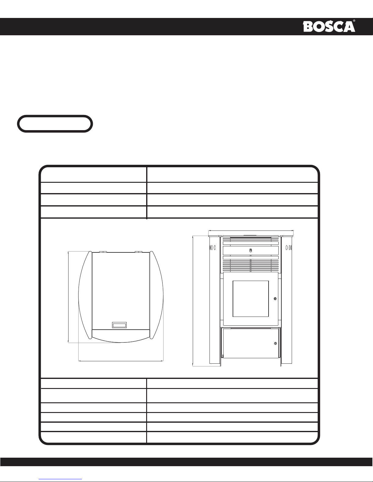
SPECIFICATIONS
Width:
Height:
Depth:
Weight:
25,6 in.
(650 mm.)
23.2 in.
36.5 in
25,6 in
295 lbs.
23.2 in.
(590 mm.)
36,5 in.
(926 mm.)
23,2 in.
(590 mm.)
TOP VIEW
Flue size: 3” or 4”
Hopper Capacity: 66 lbs. (this can vary widely depending on pellet size,
Emmisions Rate: 1,2 grs/hour (EPA Certified).
Burn time: 0,75 lb. to 4 ½ lbs. per hour
BTU range: 8,200 to 40,000
Approved installations: mobile home, alcove, conventional.
length, and diameter)
FRONT VIEW
fig. Nº2fig. Nº1
-5-
OWNER´S MANUAL
PREPARATION
Factory packaging must be removed, and some minor assembly work is required prior to installation. Access to the rear of the stove
is necessary.
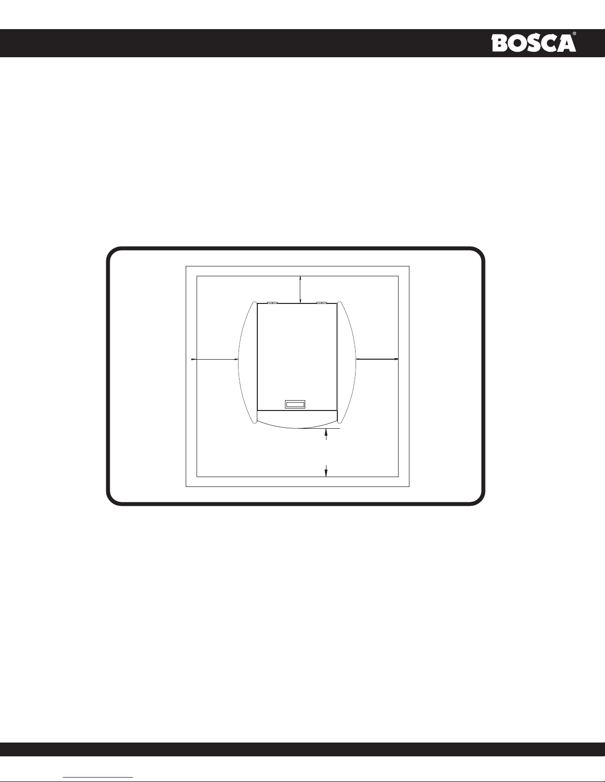
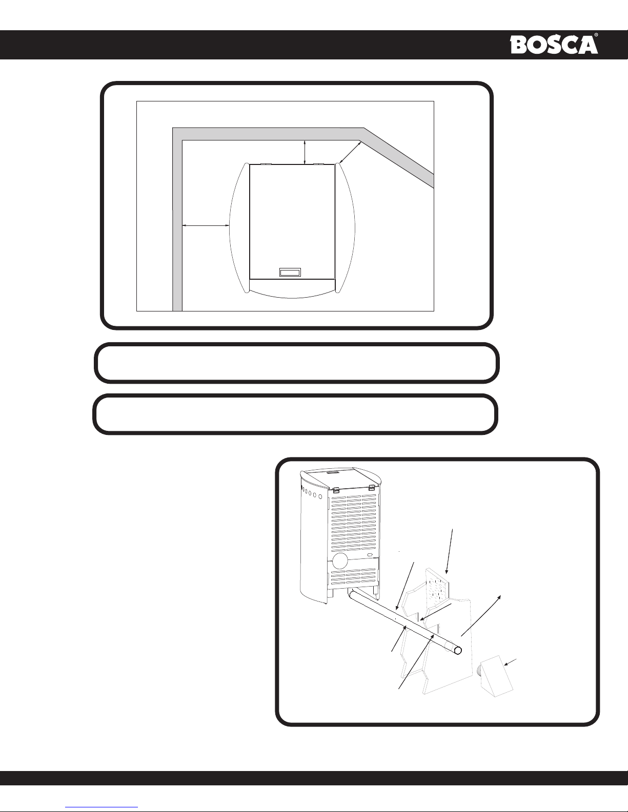
CLEARANCES
The BOSCA SPIRIT 500 Pellet stove has been tested and listed for installation in residential, mobile home
and alcove applications.
FLOOR PROTECTION: Freestanding installations, minimum 29,2" wide by 34,0" deep. The stove must be placed on a continuous
(grouted joints) noncombustible material such as ceramic tile, cement board, brick, 3/8” millboard or equivalent, or other approved
or listed material suited for floor protection (refer to fig. Nº 3) .
1 in.
(25 mm.)
3 in.
(76 mm.)
3 in.
(76 mm.)
MINIMUM
6 in.(152 mm.)
fig. Nº3
NOTE: ceramic tile, or any tile, requires a continuous sheet beneath to prevent the possibility of embers falling through to the
combustible floor if cracks or separation should occur in the finished surface, this would include floor protection for Built-in raised
hearths. Check local codes for approved alternatives.
Clearances are measured from the sides, back and face (door opening) or stove body (refer to fig. Nº 4).
The clearances may only be reduced by means approved by the regulatiory authority.
-6-
OWNER´S MANUAL
(76 mm.)
Side wall
3 in.
Back wall
(76 mm.)
3 in.
3 in.
(76 mm.)
fig. Nº4
DO NOT USE MAKESHIFT MATERIALS OR COMPROMISES IN THE
INSTALLATION OF THIS UNIT.
INSTALL VENT WITH CLEARANCES SPECIFIED BY
THE VENT MANUFACTURER.
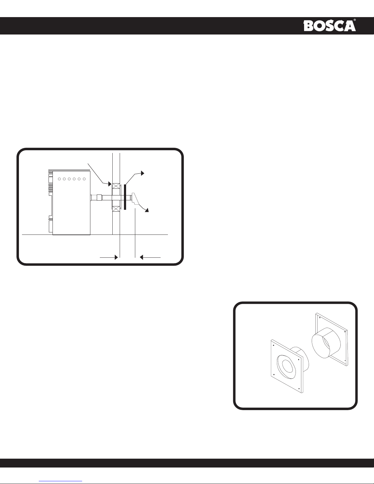
COMBUSTION AIR SUPPLY
For a mobile home installation the stove must be
connected. To an outside source of combustion air. A
2” inside diameter metallic pipe, either flexible or rigid,
may be attached to the inlet at the stove’srear (refer to
fig. Nº5). A rodent guard (minimum 1/4” wire mesh)
/wind hood must be used at the terminus. All
connections must be secured and airtight by either using
the appropriately sized hose clamp and/or UL-181-AP
foil tape.
CUT A MINIMUN 2"
DIAMETER HOLE IN
THE WALL
2" FLEX DUCT
NON COMBUSTIBLE
SELECT A LOCATION BETWEEN
FRAMING MEMBRES FOR THE
OUTSIDE AIR HOLE
WALL
COVER
PLATE
SEAL THE AREA AROUND
THE TUBE TO PREVENT AIR
FROM ENTERING THE WALL
SEAL THE
VENT WITH
SILICONE
RAIN
HOOD WITH
RODENT
SCREEN
fig. Nº5
-7-
OWNER´S MANUAL
For Mobile home installations only: 2” inside diameter pipe may be used for first 5 feet of combustion air supply run. From 5 to
10 feet use 2 3/4” inside diameter pipe. No combustion air supply may exceed 10 feet.
Sources of Outside Combustion Air
In fireplaces
- Chimney top.
- Ash clean out door.
For freestanding installations
- A hole in floor near stove rear terminating only in a ventilated crawl space.
- A hole in the wall behind the stove.
WHEN OUTSIDE AIR IS NOT USED
If outside air is not used, it is important that combustion air is easily available to the air inlet. A closeable outside air register can be
used in tightly insulated homes.
VENTING
The BOSCA SPIRIT 500 Pellet stove is certified for use with listed TYPE L-Vent, 3” or 4” diameter in size. The stove was tested with
Simpson Duravent brand. Class “A” chimney is not required. Refer to the instructions provided by the vent manufacturer, especially
when passing through a wall, ceiling or roof.
This is a pressurized exhaust system. All vent connector joints must be sealed with 500 ºF (260 ºC) RTV silicone sealant to
ensure consistent performance and avoid smoke spillage. All horizontal connector joints must be sealed with UL-181-AP foil
tape. We require that all vertical vent connector joints be secured with a minimum of 3 screws.
DO NOT CONNECT THIS UNIT TO A CHIMNEY FLUE SERVING
DO NOT CONNECT TO ANY AIR DISTRIBUTION DUCT OR SYSTEM
DO NOT INSTALL A FLUE DAMPER IN THE EXHAUST VENTING
INSTALL VENT AT CLEARANCES SPECIFIED BY THE VENT
SECURE EXHAUST VENTING SYSTEM TO THE APPLIANCE WITH
AT LEAST 3 SCREWS. ALSO SECURE ALL CONNECTOR PIPE
JOINTS WITH AT LEAST 3 SCREWS THROUGH EACH JOINT.
Equivalent Vent Length (EVL)
ANOTHER APPLIANCE.
SYSTEM OF THIS UNIT.
MANUFACTURER.
The longer the run of pipe in your installation, the more restrictions there is in the system. Therefore, larger diameter pipe should be
used.
Use 4” pipe if you have more than 15 feet of equivalent vent length. Horizontal runs shall not exceed 10 feet of EVL. It is recommended
that vertical runs be a minimum of 8 feet.
-8-
OWNER´S MANUAL
To calculate EVL, use the following conversions:
90º elbow or “T” = 5 equivalent feet
45º elbow = 3 equivalent feet
Horizontal Pipe Run = 1 equivalent foot per actual foot
Vertical Pipe Run = 0.5 equivalent foot per actual foot
NOTE: At altitudes above 3,000 feet, we suggest the use of 4” diameter vent at an EVL of 7 feet or more.
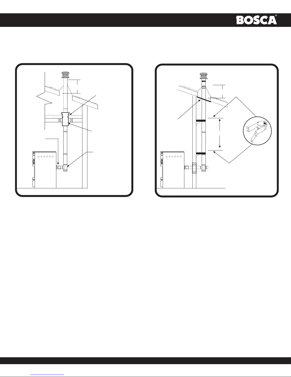
FREESTANDING INSTALLATIONS
Horizontally Through Wall
(Refer to fig. Nº 6)
Fig. Nº 6. Locate terminations:
WALL THIMBLE
12 INCHES
MINIMUN
OPTIONAL
HOUSE
SHIELD
SQUARE
HORIZONTAL
CAP
a) not less than 3 feet above any forced air inlet located with
10 feet;
b) not less than 4 feet below or horizontally from, or on foot
above, any door, window or gravity air inlet into any building;
c) not less than two feet from an adjacent building and not
less than 7 feet above grade when located adjacent to a
public walkway. Mobile home installations must use a spark
arrester.
NOTE: In Canada, where passage through a wall of
combustible construction is desired, the installation shall
conform to CAN/CSA - B 365.
fig. Nº6
NOTE: Follow L-Vent chimney manufacturer’s instructions.
• Position stove, adhering to clearances show in fig. Nº4
• Locate position of hole in wall; directly behind stove exhaust vent.
• Always maintain 3” clearance from combustible materials.
• Install L-Vent wall thimble per L-Vent manufacturer’s instructions
(refer fig. Nº 7).
• Attach enough piping to penetrate and extend at least 12” beyond
exterior walls. An 5-foot vertical pipe run is suggested where
possible to reduce the possibility of smoke s pillage in the event of
a loss of negative pressure.
• Attach cap and seal outside wall thimbles with non-hardening
waterproof mastic.
• Termination should not be located so that hot
exhaust gases can ignite trees, shrubs, or grasses or be a
hazard to children. Exhaust gases can reach temperatures
of 500ºF and cause serious burns if touched.
GALVANIZED EXTERIOR
(STAINLESS STEEL FOR
CORVENT)
BLACK
INTERIOR
fig. Nº7
-9-
OWNER´S MANUAL
Vertically With New Chimney System
( Refer to fig. Nº 7a-7b)
24" MIN
ATTIC
INSULATION
SHIELD
CEILING
SUPPORT/
PIPE
ADAPTER
FIRESTOP
SPACER
TEE WITH
CLEAN-OUT
ADAPTER
fig. Nº7a
NOTE: Follow L-Vent chimney manufacturer’s instructions.
24" MIN
FIRESTOP
4 FT.
fig. Nº7b
OPTION: Install L-Vent elbow in place of clean-out tee. Locate stove. Drop plumb bob to center of tee outlet, mark point on ceiling. Install
ceiling support and L-Vent pipe per L-Vent manufacturer’s instructions.
• Always maintain 3” clearance from combustible materials. When passing through additional floors or ceilings, always install firestop
spacer.
• After lining up for hole in roof, cut either around or square hole in roof, always 3” larger all the way around pipe. Install upper edge
and sides of flashing under roofing materials, nail to the roof along upper edge. Do not nail lower edge. Seal nail head with nonhardening waterproof mastic.
• Apply non-hardening, waterproof mastic where the storm collar will meet the vent and flashing. Slide storm collar down until it
sits on the flashing. Seal and install cap. Mobile home installations must use a spark arrester.
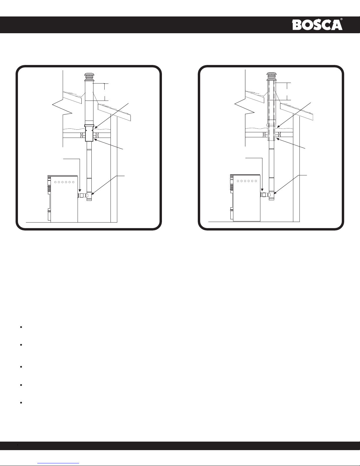
Vertically Into Existing Chimney System
( Refer to fig. Nº 8a-8b)
Adapters are available to adapt from 3” L-Vent to 6” or 8” Class-A chimney. (Fig. Nº 8a)
As an alternative, 3” or 4” L-Vent can be run inside existing chimney to termination. (Fig. Nº 8b). This is the preferred method.
Follow guidelines for equivalent.
-10-
OWNER´S MANUAL
24" MIN
ATTIC
INSULATION
SHIELD
CEILING
SUPPORT/
PIPE
ADAPTER
FIRESTOP
SPACER
TEE WITH
CLEAN-OUT
ADAPTER
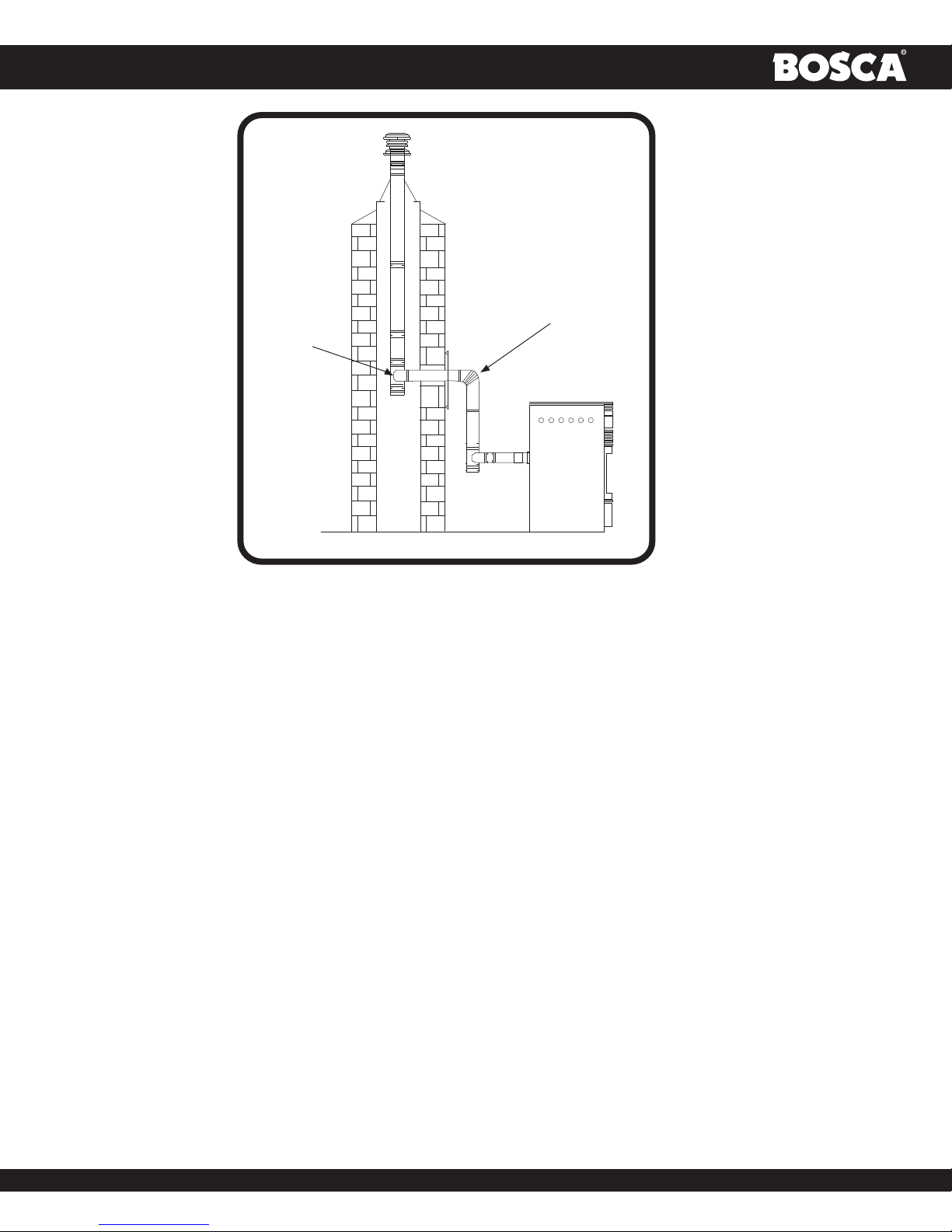
Vertically Into Existing Masonry Fireplace
(Refer to fig. Nº9)
fig. Nº8a
PIPE
ADAPTER
24" MIN
ATTIC
INSULATION
SHIELD
CEILING
SUPPORT/
FIRESTOP
SPACER
TEE WITH
CLEAN-OUT
ADAPTER
fig. Nº8b
NOTE: Follow L-Vent chimney manufacturer’s instructions.
• Have the masonry chimney inspected by a qualified chimney sweep or installer to determine its structural condition.
• You will need a pipe length equal to the chimney height from the hearth. If outside combustion air is to be used, you will need a pipe
length equal to the chimney height plus 18 inches.
• Install a blanking plate and the chimney pipe, and if used the outside air pipe.
Attach the L-Vent adapter, a section of pipe and clean out tee, making sure the clean-out tee is centered in the chimney flue area. Use RTV,
metallic tape, and a minimum of three self-taping screws at all joint connections to ensure a tight seal.
Install and seal the top plate from step 3 with non-hardening mastic. Slip the storm collar over the pipe, and while holding
the pipe at the proper elevation, affix the collar with a minimum of three 1/4” stainless steel sheet metal screws. Seal all
joints and seams around the collar.
Connect the horizontal pipe by pushing it through the hole in the masonry and lining it up with the branch in the tee.
Push the pipe into the tee while twisting it to lock it into the tee.
If desired, once the horizontal pipe is in place, the space between the pipe and masonry may be filled with high-temperature
grout.
Install the trim collar. An adjustable pipe length and adapter may be needed to finish the connection to the stove.
-11-
OWNER´S MANUAL
REDUCTION
COLLAR OR
TRIMCOLLAR
TEE
fig. Nº9
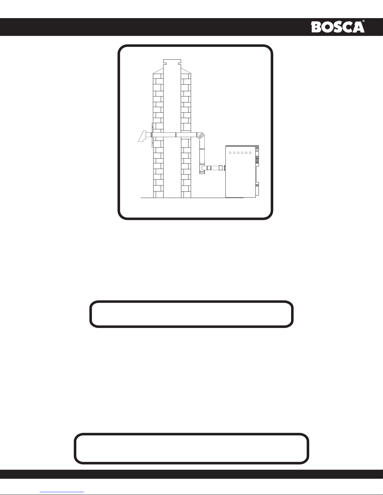
Installation Through Side of Masonry Chimney
(Refer to fig. Nº 10)
NOTE: Follow L-Vent chimney manufacturer’s instructions.
• Position the stove, adhering to the clearances in Figures 1 & 2. Mark the center of the hole where the
pipe is to pierce the masonry chimney. It will be necessary to break out the masonry around the location
of the pipe center mark. Use a 4-inch diameter hole for 3-inch pipe and 5-inch diameter hole for a
4-inch pipe.
• Measure and build chimney top plate. Cut out holes for chimney pipe, and if used cut necessar
holes for the outside air pipe. Install the tee on the bottom of the vertical pipe system and lower it
down the chimney until the center branch of the tee is level with the center of the hole in the
masonry, as shown in fig. Nº10.
• Install and seal the top plate from step 3 with non-hardening mastic. Slip the storm collar over t he
pipe, and while holding the pipe at the proper elevation, affix the collar with a minimum of three
1/4” stainless steel sheet metal screws. Seal all joints and seams around the collar.
• Connect the horizontal pipe by pushing it through the hole in the masonry and lining it up with
the branch in the tee. Push the pipe into the tee while twisting it to lock it into the tee.
• If desired, once the horizontal pipe is in place, the space between the pipe and masonry may be filled with
high-temperature grout.
• Install the trim collar. An adjustable pipe length and adapter may be needed to finish the connection
to the stove.
-12-
OWNER´S MANUAL
fig. Nº10
ELECTRICAL INSTALLATION
This stove is provided with a 6-foot grounded electrical cord extending from the rear of the stove. We recommend connecting
to a good quality surge protector that is plugged into a standard three-prong, 120V, 60hz electrical outlet. Voltage variations
can lead to serious performance problems. The BOSCA SPIRIT 500 Pellet stove electrical system is designed for 120V AC with
no more than 5% variation. Bosca cannot accept responsibility for poor performance or damage due to inadequate voltage. If
connected to an older, two-prong outlet, a separate ground wire should be run to a proper ground (refer this to a qualified
technician). Always route the electrical cord so that is will not come in contact with any hot part of the stove.
SPECIAL MOBILE HOME REQUIREMENTS
WARNING: DO NOT INSTALL IN A SLEEPING ROOM.
For installation in a mobile home, an outside source of combustion air must be used (see “COMBUSTION AIR SUPPLY”).The outside
source of combustion air must be unrestricted while the appliance is in use to prevent room air starvation, which causes smoke spillage.
Some spillage could also set off smoke alarms.
• The stove must be grounded to the steel chassis of the home with 8 Ga. Copper wire using a serrated or star washer
to penetrate paint or protective coating to ensure grounding.
• The stove must be securely fastened to the floor of the mobile home using 2, 1/4” lag bolts that are long enough to
go through both a hearth pad, if used, and the floor of the home.
• Use RTV High Temp silicone to create an effective vapor barrier at the location where the chimney or other component
penetrates to the exterior of the structure.
• Refer to “VENTING” for proper exhaust configurations.
THE STRUCTURAL INTEGRITY OF THE MOBILE HOME FLOOR, WALL
AND CEILING/ROOF MUST BE MAINTAINED.
CAUTION
-13-
OWNER´S MANUAL
OPERATION
PANEL CONTROLS
The blowers and automatic fuel supply are controlled from a panel on the top left-hand
side of the stove.
The control panel functions are as follows:
On/Off Switch
When pushed, the stove will automatically ignite. No other firestarter is necessary. The
igniter will stay on for at least 10 and up to 15 minutes, depending on when Proof of
Fire is reached. The fire should start in about 5 minutes.
The green light located above the On/Off button (in the On/Off box) will flash during
the ignition start-up period (see fig. Nº11).
The Feed Rate Advance is inoperable during the ignition start period. When the red light
continuously stays on, the Feed Rate Advance can be adjusted to achieve the desired heat
output.
NOTE: If the stove has been shut off, and you want to re-start it while it is still warm, the
“On/Off” button must be held down for 2 seconds.
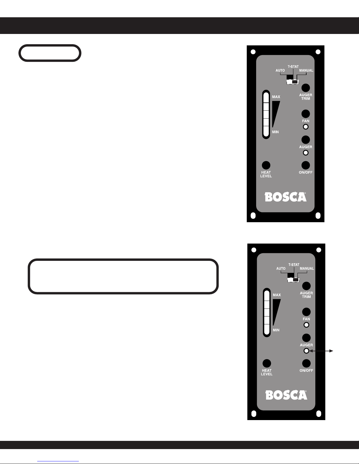
Fuel Feed Switch
When the “Fuel Feed” button is pushed and held down the stove will feed pellets
continuously into the burnpot. While the stove’s auger system is feeding pellets the
amber light (in the “Fuel Feed” box”) will be on. (See fig. Nº12)
CAUTION
DO NOT USE THIS CONTROL DURING NORMAL OPERATION
BECAUSE IF COULD SMOTHER THE FIRE AND LEAD TO A
DANGEROUS SITUATION.
4
3
2
1
fig. Nº11
High Fan Switch
The room air fan speed varies directly with the feed rate. The “HIGH FAN” switch
overrides this variable speed function. It will set the room air blower speed to high at
any feed rate setting.
When the “HIGH FAN” button is pushed the room air fan will switch to its highest
setting.
When this button is pushed again, the room air fan will return to its original setting
based on the Feed Rate Advance setting.
Reset Trim
Different size and quality pellet fuel may require adjustment of the “1” feed setting on
the Feed Rate Advance bar graph. This is usually a one-time adjustment based on
the fuel you are using. The “RESET TRIM” button when adjusted will allow for 3
different feed rate settings for the #1 feed setting only. To adjust simply push the
“RESET TRIM” button while the stove is operating at setting “1” and watch the bar
graph.
-14-
4
3
2
1
Amber
Light On
fig. Nº12

OWNER´S MANUAL
When the “1” and “3” lights are illuminated on the bar graph the low feed rate is at its “lowest setting". (approx. 0.9 pounds per hour).
When the “1” light is illuminated on the bar graph the low feed rate is at its “normal” setting.
When the “1” & “4” lights are illuminated on the bar graph the low feed rate is at its “highest” setting.
NOTE: When the stove is set on “1” the “reset trim” values will be shown on the Feed Rate Advance bar graph. For example if the
Reset Trim is set to low the “1” and “3” lights will be illuminated on the bar graph.
Heat Level Advance
This button when pushed will set the pellet feed rate, hence the heat output of your stove. The levels of heat output will incrementally
change on the bar graph starting from level “1” to “4”.
NOTE: When dropping more than 2 heat level settings (i.e. 4 to 1) push the “High Fan” button and allow the room air fan to run
at that setting for at least 5 minutes to prevent the stove from tripping the high temp thermodisc. If the high temp thermodisc does
trip see “SAFETY FEATURES”.
PROPER FUEL
THIS STOVE IS APPROVED FOR BURNING PELLETIZED WOOD FUEL ONLY
Factory-approved pellets are those 1/4” or 5/16” in diameter and not over 1” long. Longer or thicker pellets sometimes bridge the
auger flights, which prevents proper pellet feed. Burning wood in forms other than pellets is not permitted. It will violate the building
codes for which the stove has been approved and will void all warranties. The design incorporates automatic feed of the pellet fuel
into the fire at a carefully prescribed rate. Any additional fuel introduced by hand will not increase heat output but may seriously
impair the stoves performance by generating considerable smoke. Do not burn wet pellets. The stove’s performance depends heavily
on the quality of your pellet fuel.
Avoid pellet brands that display these characteristics:
Excess Fines: “Fines” is a term describing crushed pellets or loose material that looks like sawdust or sand. Pellets can be screened
before being placed in a hopper to remove most fines.
Binders: Some pellets are produced with materials to hold them together, or “bind” them.
High Ash Content: Poor quality pellets will often create smoke and dirty glass. They will create a need for more frequent
maintenance. You will have to empty the burnpot plus vacuum the entire system more often. Poor quality pellets could damage
the auger. Bosca cannot accept responsibility for damage due to poor quality pellets. Your dealer can recommend a good quality
pellet dealer in your area.
Proper Fuel Storage: Keep fuel raised off the floor and in a covered area to avoid moisture and water contact.
CAUTION: DO NOT PLACE FUEL WITHIN SPACE HEATER INSTALLATION OR
WITHIN THE SPACE REQUIRED FOR CHARGING AND ASH REMOVAL.
PRE- START- UP CHECK
Remove burnpot, making sure it is clean and none of the air holes are plugged. Clean the firebox, and then reinstall burnpot. Clean
door glass if necessary (a dry cloth or paper towel is usually sufficient). Never use abrasive cleaners on the glass or door. Check fuel
in the hopper, and refill if necessary. Make sure hopper lid id closed, If left open auger will not feed pellets.
BUILDING A FIRE
Never use a grate or other means of supporting the fuel. Use only the Bosca approved burnpot.
NOTE: During the first few fires, your stove will emit an odor as the high temperature paint cures or becomes seasoned to the metal.
Maintaining smaller fires will minimize this. Avoid placing items on stovetop during this period because paint could be affected.
NOTE: Bosca pellet stoves are equipped with a hopper safety switch, if hopper lid is open the auger will not drop pellet fuel. If the
hopper lid is left open for a prolonged period of time the unit will shut down.
-15-
OWNER´S MANUAL
NOTE: You will have to prime the auger system before stove will ignite, you may have to go thru 2 to 3 start up cycles each cycle
last 15 minutes stove will shut you then must go thru start procedure again.
NOTE: To speed up the time it takes to prime auger system you may press and hold the hopper switch, and press and hold the auger
button on control board once you have turned stove on by pressing the power button. This allows the auger to turn continually when
you hear pellets drop into burn pot close hopper lid and unit will continue in start up mode.
A.- Fill hopper with pellet fuel.
B.- Make sure burn pot is seated in correct position and or clean.
C.- Press power button "On/Off" make sure light comes on and close hopper lid.
D.- Adjust damper to 1/2” to 3/4” open (pushed in is open). This will vary depending on your installation and elevation. Once fire is
established, adjust for desired flame increasing the amount the damper is open as the heat setting is increased. (see “DAMPER
CONTROL”)
E.- Adjust the pellet fuel feed rate to desired setting by pressing Feed Rate Advance "Heat Level" button.
If stove doesn’t start in 15 minutes, press Power "On/Off, wait a few minutes and go thru start procedure again with step C.
DAMPER CONTROL
The Damper Control rod, on the stove’s lower right front
side, adjusts the combustion air. This control is necessary
due to the varied burn characteristics of individual installations, different
pellet brands and pellet feed rates. It allows you to improve the efficiency
of your stove. Providing correct combustion air will reduce the frequency
of cleaning your glass door and prevent the rapid buildup of creosote
inside your stove and chimney. You should adjust the damper based on
the fire’s appearance. A low, reddish, dirty fire can be improved
by pushing the damper in slightly. A “blow torch” fire can be improved by
pulling the damper out a bit.
As a general rule, on lower feed rate settings, the damper
should be out farther. On higher feed rates, the damper should be more
open. Through trial and error, you will find the best setting. Consult your
dealer if you need help.
NOTE: On “1”, damper should be out approximately 1/2”
to 3/4”. If damper is out too far, it can cause the fire to go
out. Remember push in damper for more air, pull out for
PUSH (open)
less air.
PULL (close)
OPENING DOOR
Fig. Nº12
If the door is opened while the stove is in operation it must be closed within 30 seconds or the stove will shut down.
If the stove shuts down, push the “Power” button to continue the operation of your stove.
ROOM AIR FAN
When starting your stove the Room Air Fan will not come on until the stove’s heat exchanger warms up. This usually takes about 10
minutes from start-up.
IF STOVE RUN OUT OF PELLETS
The fire goes out and the auger motor and blowers will run until the stove cools. This will take 30 to 45 minutes. After the stove
components stop running, the “Power” and the BAR GRAPH lights stay on for 10 minutes. After the 10 minutes the “3” light on the
bar graph will flash and the “Power” light will go off. To restart, refill hopper, press “Power” button, and then press “Fuel Feed” button
until pellets begin to fall into burnpot.
-16-

OWNER´S MANUAL
REFUELING
We recommend that you not let the hopper drop below 1/4 full.
KEEP HOPPER LID CLOSED AT ALL TIMES EXCEPT WHEN REFILLING.
IF LEFT OPEN AUGER WILL NOT FEED.
DO NOT OVERFILL HOPPER.
SHUTDOWN PROCEDURES
Turning your BOSCA SPIRIT 500 Pellet stove off is a matter of pressing the “Power” control panel switch. The red light will go out.
The blowers will continue to operate until internal firebox temperatures have fallen to a preset level.
SAFETY FEATURES
A.- Your stove is equipped with a high temperature thermodisc. This safety switch has two functions:
1. To recognize an overheat situation in the stove and shut down the fuel feed or auger system.
2. In case of a malfunctioning convection blower, the high-temperature thermodisc will automatically shut down the auger,
preventing the stove from overheating.
NOTE: The thermodisc has no reset button and will reset itself once the stove has cooled. The manufacturer recommends
that you call your dealer if this occurs as this may indicate a more serious problem. A service call may be required.
B.- If the combustion blower fails, an air pressure switch will automatically shut down the auger.
NOTE: Opening the stove door for more than 30 seconds during operation will cause enough pressure change to activate the air
switch, shutting the fuel feed off. Close the door and press “On/Off” button to continue operation of your stove.
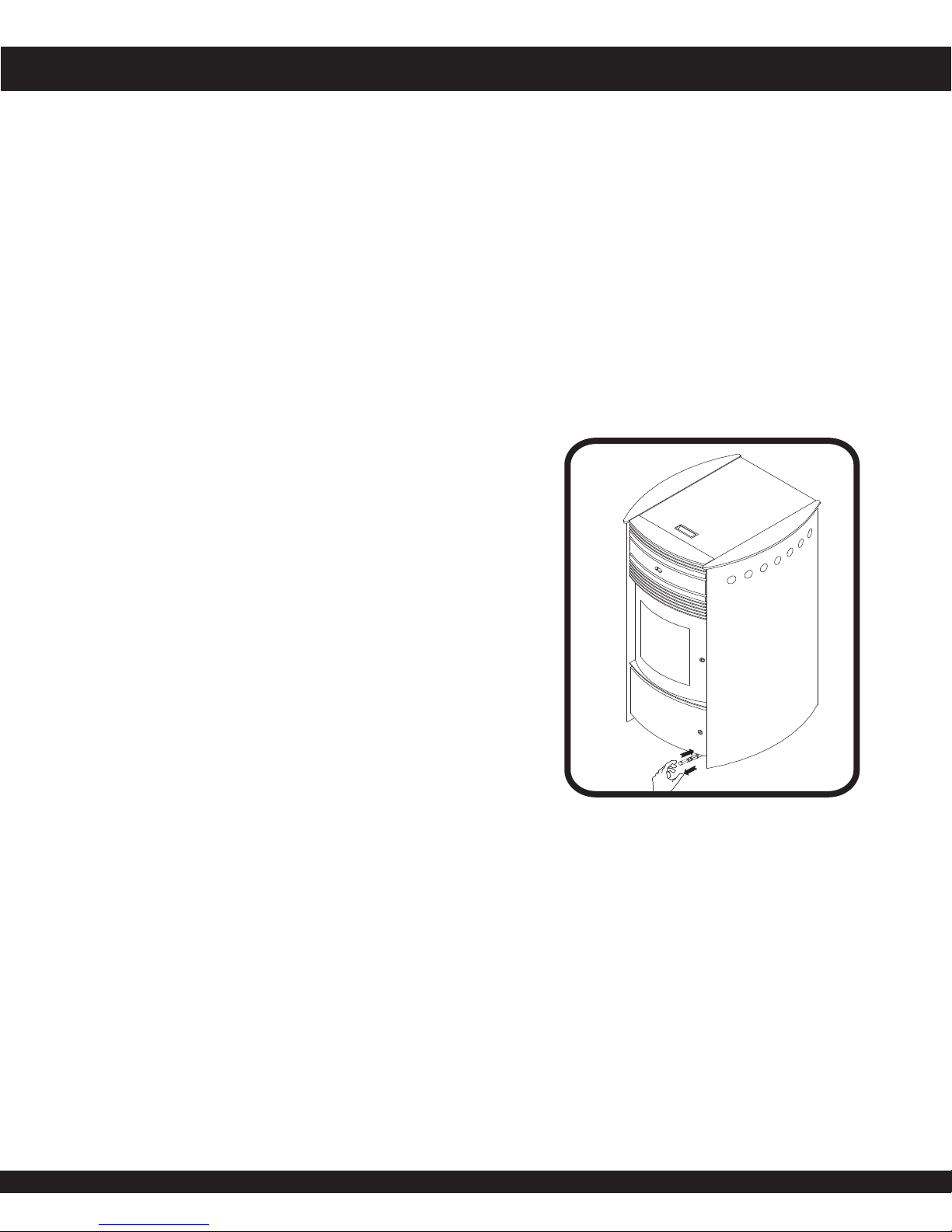
THERMOSTAT INSTALLATION
Your BOSCA SPIRIT 500 Pellet stove is ready to plug-in a thermostat (a millivolt thermostat is required).
To connect your stove to a thermostat, follow these instructions:
• Unplug the stove from power outlet
• Find the white/red wire to connect the thermostat, located at the back of the stove, near the Control Board.
• Plug the wires of the thermostat.
• Plug the stove to the power outlet..
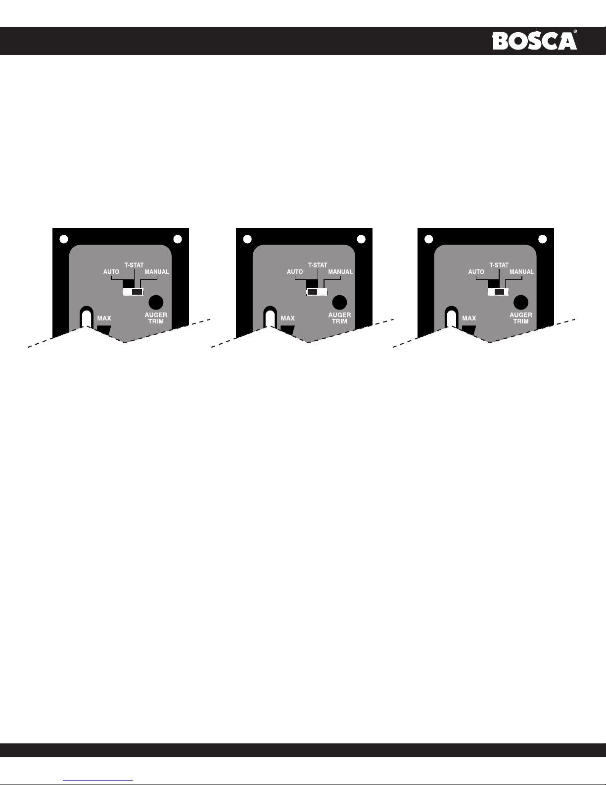
Modes
To switch between any of the three modes the stove must be shut off, the new mode selected, and the stove restarted.
Manual Mode
(see fig. Nº14 a)
In this mode, the stove will operate only from the Control Panel, as detailed in the “OPERATION” section of this Owner’s Manual.
On/Off Thermostat Mode
(see fig. Nº14 b)
In this mode when the home is warm enough the stove will shut off. The fans will continue to run until the stove cools.
When the home cools below the thermostat setting, the stove will automatically restart and run at the last feed rate setting.
-17-
OWNER´S MANUAL
4
High/Low Thermostat Mode
(see fig. Nº14 c)
When engaged in this mode, the stove will automatically switch between two settings. When warm enough, it will switch to the
#1 or low setting. The room air blower will also slow to its lowest speed.
NOTE: You must press “On/Off” button to start and stop stove when in this mode.
The Heat Level Advance setting on the bar graph will stay where it was initially set. When the house cools below the thermostat,
the stove will switch to the feed rate of the heat level advance setting.
MANUAL
fig. Nº14 a fig. Nº14 b fig. Nº14 c
Set damper control rod approximately 1/2” to 3/4” out. This will vary depending on elevation and weather conditions. Observe stove's
operation and adjust damper
ON/OFF
HIGH/LOW
-18-

OWNER´S MANUAL
OPERATING SAFETY PRECAUTIONS
PLEASE READ THIS !
Hot while in operation. Keep children, clothing, and furniture away. Contact may cause skin burns.
If you notice a smoldering fire (burnpot full but no visible flame) AND a heavy smoke buildup in firebox immediately TURN
OFF the stove, but DO NOT unplug it. Do not open the door, change the damper setting or tamper with any controls
on the stove. Wait until firebox clears, and blowers shut down, do as instructed in "PRE -START UP CHECK" and “BUILDING
A FIRE”, then attempt to restart the fire. If the problem persists contact your Dealer.
WARNING: DO NOT OPEN THE DOOR DURING THE START UP CYCLE AND DO NOT ADD PELLETS TO THE
BURNPOT BY HAND AT ANY TIME, OTHERWISE A DANGEROUS CONDITION COULD RESULT.
Pellets should be stored in a dry place. The pellets should not be stored within 12” of the stove.
DO NOT STORE OR USE FLAMMABLE LIQUIDS, EXPECIALLY GASOLINE, IN THE VICINITY OF YOUR SPIRIT 500 PELLET.
NEVER USE A GAS OR PROPANE TORCH, GASOLINE, GASOLINE-TYPE LANTERN FUEL, KEROSENE, CHARCOAL
LIGHTER FLUID OR SILIMAR FLUIDS TO START OR “FRESHEN UP” A FIRE IN THIS HEATER.
WARNING: DO NOT OVERFIRE THIS STOVE. This may cause serious damage to your stove and void your warranty. It also may
create a fire hazard in your home. IF ANY EXTERNAL PART OF THE UNIT BEGINS TO GLOW, YOU ARE OVERFIRING. Immediately
press the “POWER” switch on the Control Panel.
KEEP ALL LOOSE OR MOVEABLE HOUSEHOLD COMBUSTIBLES, SUCH AS FURNITURE, DRAPES, TOYS, ETC. AT LEAST
THREE FEET FROM THE OPERATING STOVE.
Maintain proper ventilation. It is important that adequate oxygen be supplied to the fire for the combustion
process. Modern houses are often so well insulated that it may become necessary to open a window
slightly or install an outside air vent to provide sufficient combustion air. Since heating with a solid fuel is
potentially hazardous, even with a well made and thoroughly tested stove, it would be wise to install
strategically placed smoke detectors and have a fire extinguisher in a convenient location, near an exit.
Do not open stove door when operating unless necessary. This will create a dirty, inefficient burn and could allow smoke spillage or
sparks to escape.
Do not permit operation by young children or those unfamiliar with stove’s operation.
Do not service or clean this appliance without disconnecting the power cord.
Do not abuse the door glass by striking, slamming or similar trauma. Do not operate the stove with the glass removed, cracked or
broken.
If the stove is installed in a room without air conditioning, or in an area where direct sunlight can shine on the unit, it is possible this
can cause the temperature of the stove to rise to operational levels; one of the sensors could then make the convection fan and /or
feed system start on its own. It is recommended that the stove be unplugged when not in use for extended amounts of time (i.e. during
summer months).
Do not burn garbage or flammable fluids such as gasoline, lighter fluids or engine oil.
-19-
OWNER´S MANUAL
MAINTENANCE
FAILURE TO CLEAN AND MAINTAIN THIS UNIT
AS INDICATED CAN RESULT IN POOR PERFORMANCE AND SAFETY
HAZARDS. NEVER CLEAN WHEN HOT.
NOTE: Inspect burnpot periodically to see that holes have not become plugged, if so, clean thoroughly.
MAINTENANCE TOOL
A tool has been provided to help with the following functions:
Stirring pellets in hopper: Unlike liquids in a tank, pellets do not drain evenly into the auger. Bridging across the opening can occur.
Pellets can hang up on the sides of the hopper. Occasionally “stirring” the hopper can help.
NOTE: To prevent bridging of pellets, common wax paper can be rubbed on the sidewalls and bottom of the hopper.
Scrape ashes from burnpot to ash drawer.
ASH DISPOSAL
Ash should be placed in a metal container with a tight-fitting lid. The closed container of ashes should be placed on a noncombustible
surface or on the ground, well away from all combustible materials pending final disposal. If ashes are disposed of by soil burial or
otherwise locally dispersed, they should be retained in the closed container until all cinders have thoroughly cooled.
ASH REMOVAL
Remove ashes periodically as they fill the firebox. To remove ashes:
• Make sure fire is out and firebox is cool.
• Clean heat exchanger tubes (see “CLEANING” and fig. Nº 20).
• Remove the burnpots inner sections by grasping it and pulling straight up.
• Empty ashes from the inner section and scrape with cleaning tool. Make sure holes are not plugged.
• Vacuum to remove ashes from the burn chamber interior and the burnpot shell. Or sweep ash with small broom into ash
cleanout drawer.
WARNING:
MAKE SURE ASHES ARE COOL TO THE TOUCH BEFORE USING A VACUUM
(See “VACUUM USE”.)
• Dispose of ashes properly (See “ASH DISPOSAL” above).
• Replace inner section into burnpot; make sure it is level and pushed all the way back down and that the igniter hole is
to the rear when it is reinstalled (see fig. Nº 19 a,19 b,19 c ).
• Check gasket condition on air intake tube.
• Make sure the burnpot is level and pushed all the way in, if the collar on the burnpot attached to the fresh air tube is not
pushed back to meet the firebox wall, the Hot Rod will not work properly.
-20-
 Loading...