

Page 1
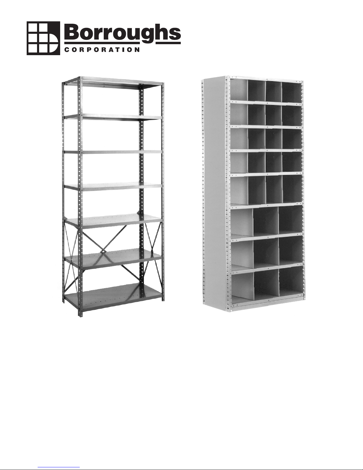
Box Edge Plus® Steel Shelving
Installation Instructions
––––––––– IMPORTANT –––––––––
PRODUCT LIABILITY INFORMATION
Read all instructions before proceeding with installation or shelf loading.
Vital product information pertaining to proper set-up, safe loading and cautions are included. Failure to follow these instructions may cause shelving
failure which may result in personal injury and/or property damage.
- 1 -
RETAIN THIS MANUAL
FOR FUTURE REFERENCE
02-50000-00C
December 2002
Page 2
GENERAL INSTRUCTIONS
In preparing for multiple section installations, it is recom-
mended that a floor plan with elevations be available at the
job site. It is further recommended that the floor be marked
to indicate where the rows will be and where the aisles will
be so that the distributed material can be stacked for
minimal interference. This will also show where obstruc-
tions will occur. The sections may then be erected along
the lines so that once the row is in place, the bracing bolts
can be tightened and each section will remain square.
Rough or uneven floors should be compensated with
shims. It is required that sections not be out of plum more
than
1" in ten feet or more of height
.
BASIC DATA
WIDTHS:
Nominal unit width: 24", 36", 42" or 48"
Actual beaded post unit width is the nominal width plus 1"
Actual angle post unit width is the nominal width
Actual high-rise post unit width is the nominal width plus 2"
DEPTHS:
Nominal depth: 12", 15", 18", 24", 30", 32" or 36"
Actual beaded post unit depth is the nominal depth plus 15/32"
with beaded post in front and angle post in back
Actual angle post unit depth is the nominal depth
Actual high-rise post unit depth is the nominal depth plus 15/32"
with high-rise post in front and angle post in back
Actual high-rise post unit depth is the nominal depth plus 1-15/16"
with high-rise posts in front and in back
HEIGHTS:
Nominal height: One foot increments from 3'3" to 16'3"
Actual height is the nominal height minus 1/4" ±1/16"
NOTE: Unit anchoring is recommended when the height to depth ratio exceeds 4.
EXAMPLE:
LENGTH OF RUN:
Actual length of beaded post shelving run in nominal unit width per unit
Actual length of angle post shelving run in nominal unit width per unit
Actual length of high-rise post shelving run is nominal unit width per unit
CLEAR SHELF OPENING:
Actual clear opening between beaded posts is the nominal width minus 1"
Actual clear opening between angle posts is the nominal width minus 2"
Actual clear opening between high-rise posts in the nominal width minus 2"
Vertical clearance between shelves is equal to center-to-center shelf spacing minus 1-7/32"
VERTICAL ADJUSTMENT:
All shelves are adjustable on 1-1/2" centers
7'3" high x 18" deep unit has a height to depth ratio of 4.873
and should be anchored to a firm restraint such as a floor, wall or tied overhead across
the aisle to an opposite upright assembly.
plus 1/2" for each row end.
plus 1" for each row end.
+1/16"
-0"
+1/32"
-0"
+1/16"
-0"
+1/16"
-0"
+1/32"
-0"
+1/16"
-0"
+1/16"
-0"
+1/32"
-0"
+1/16"
-0"
+1/16"
-0"
SHELF CAPACITIES
BOX EDGE PLUS® 1 BOX EDGE PLUS® 2 BOX EDGE PLUS® 3
Size Shelf Capacity Shelf Capacity Shelf Capacity
24" x 12" 600 lbs.
36" x 12" 600 lbs. 800 lbs. 1100 lbs.
42" x 12" 600 lbs. 1000 lbs.
48" x 12" 400 lbs. 500 lbs. 800 lbs.
36" x 15" 600 lbs. 800 lbs. 1100 lbs.
42" x 15" 600 lbs. 1000 lbs.
48" x 15" 500 lbs. 800 lbs.
24" x 18" 600 lbs.
36" x 18" 600 lbs. 800 lbs. 1200 lbs.
42" x 18" 600 lbs. 1000 lbs.
48" x 18" 400 lbs. 500 lbs. 1800 lbs.
24" x 24" 600 lbs.
36" x 24" 600 lbs. 800 lbs. 1200 lbs.
42" x 24" 600 lbs. 1000 lbs.
48" x 24" 400 lbs. 500 lbs. 800 lbs.
36" x 30" 600 lbs. 1900 lbs.
42" x 30" 600 lbs. 1000 lbs.
48" x 30" 500 lbs. 1750 lbs.
42" x 32" 300 lbs. 650 lbs. 1000 lbs.
36" x 36" 400 lbs. 1600 lbs.
42" x 36" 450 lbs. 1600 lbs.
48" x 36" 450 lbs. 1700 lbs.
IMPORTANT:
Wall, floor or top tie anchoring is recommended for units
when the height to depth ratio exceeds 4.
Example: A 7'/84" high x 18" deep unit has a height to
depth ratio of 4.67 and should be attached to a firm
restraint, such as a floor, wall or tied overhead across the
aisle to an opposite upright assembly.
NOTE:
For more specific information on each individual component, please call our Customer Service Department at
800-748-0227 and ask for the booklet
"Box Edge Plus
Steel Shelving Detail Sheets".
®
- 2 -
Page 3
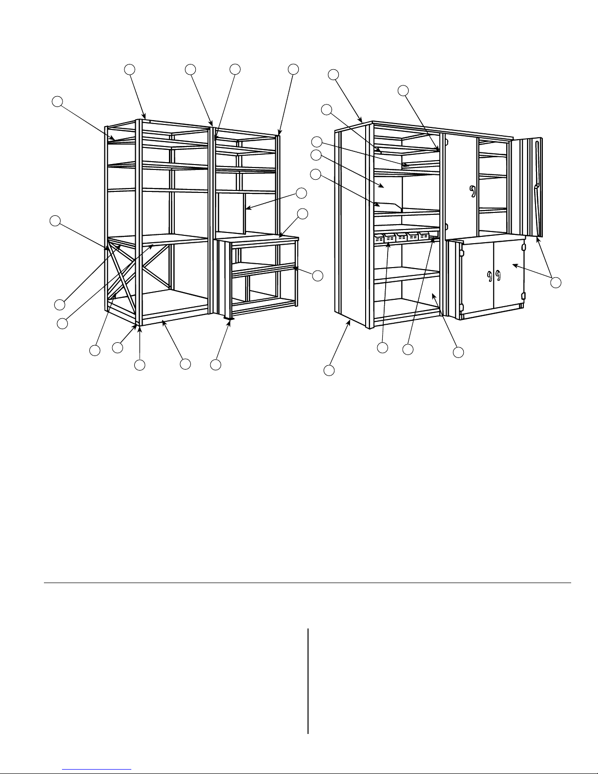
SHELVING PARTS IDENTIFICATION
34
5
6
7
8
10
9
11
12
13
12
16
15
21
20
22
14
17
23
18
24
19
26
25
1 ..... Angle Post
2 ..... Post Cover - Type 2
3 ..... Angle Post (2)
4 ..... Face Brace
5 ..... Box Edge Plus® Shelf
6 ..... Side Cross Brace
7 ..... Side Shelf Support
8 ..... Label Holder
9 ..... Back Cross Brace
10 ... Post Foot Angle
11 ... Post Cover - Type 1
12 ... Base Strip
13 ... Front Foot Plate
14 ... Bin Front
15 ... Ledge Top
16 ... Fixed Shelf Divider
17 ... Angle Post Closed Side
18 ... Shelf Box
WARRANTY
Borroughs Corporation extends to the original purchaser from the date of purchase a
5-year limited warranty against manufacturing defects in material and workmanship.
If a Borroughs product fails to perform because of a manufacturing defect,
Borroughs will examine it. If found defective, it will be repaired or replaced at our
option.
This warranty applies only to Borroughs products acquired directly from
Borroughs Corporation or from Authorized Borroughs Dealers.
This warranty does not apply to any product which has been subject to
misuse, negligence, or accident; has been damaged in shipment, storage, or
installation; has been misapplied or has been modified or repaired by unauthorized
persons or been repaired with non-standard Borroughs replacement parts. This
19 ... Shelf Box Guide
20 ... Angle Shelf Divider
21 ... Shelving Back
22 ... Flush Bar
... Cornice Top
... Shelf Bracket Clip
... Angle Post Closed Side and Angle Post (2)
... Framed Swing Doors
warranty specifically excludes claims for indirect, incidental, or consequential damages
arising in any way from a product defect. This warranty is exclusive, and exists in lieu
of all other warranties, either expressed or implied.
This warranty give you specific legal rights; you may also have other rights
which may vary from state to state.
To obtain warranty service, contact your Borroughs Selling Dealer. You must
make a written claim. Provide a copy of your purchase record and a written
description of the warranty problem with your claim. If you are unable to contact your
Dealer, contact: Borroughs Corporation, Customer Service Manager, 3002 N. Burdick
Street, Kalamazoo, MI 49004-3483.
- 3 -
Page 4
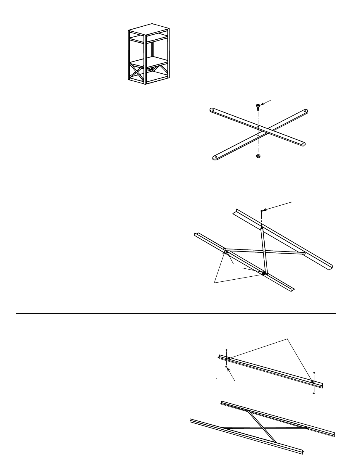
OPEN TYPE SHELVING
STEP I SWAY BRACE ASSEMBLY
After the material has been distributed to the proper location, assemble all
sway braces by loosely bolting two matched pieces together at the center.
Assemble side sway braces with 1/4-20 x 3/4" hex head cap screws and hex
nuts.
Assemble rear sway braces with 1/4-20 x 5/8" hex head cap screws and hex
nuts.
STEP 2 ROW ENDS UPRIGHT ASSEMBLY
Determine from the floor plan how may row end upright assemblies will be
required. For each one, attach a pair of side sway braces to two angle posts.
The brace bolts on the inside of the long flange. Refer to pages 10 and 11 for
the approximate, proper* location of the braces. Repeat this procedure until all
row ends are assembled.
*Pre-determine critical shelf location to avoid interference with the sway brace
bolts.
NOTE: ALL BACK AND SIDE SWAY BRACES ARE ATTACHED TO UPRIGHTS AT 30" VERTICAL SPACING.
Attach side sway braces to posts with 1/4-20 x 3/4" hex head cap screws and
hex nuts.
1/4-20 x 3/4" Hex Head Cap Screw
and Hex Nut
1/4-20 x 3/4" Hex Head
Cap Screw and Hex Nut
Automatically Spaces
This Side
30"
Bolt This Side First
STEP 3 INTERMEDIATE UPRIGHT
ASSEMBLY
Determine from the floor plan how many intermediate upright assemblies will
be required. Each intermediate consists of four angle posts and one pair of side
sway braces. Bolt two posts together (through the fourth hole from each end, in
the long flange) to form a T post. Repeat with the other two posts. The two T
posts and the side brace are now bolted together at the same level and spacing
as the row end upright assemblies (refer to Step 2). Repeat this procedure until
all intermediates are assembled.
Attach side sway braces to posts with 1/4-20 x 3/4" hex head cap screws and
hex nuts.
Fourth Hole From Each End
1/4-20 x 3/4" Hex Head Cap
Screw and Hex Nut
- 4 -
Page 5
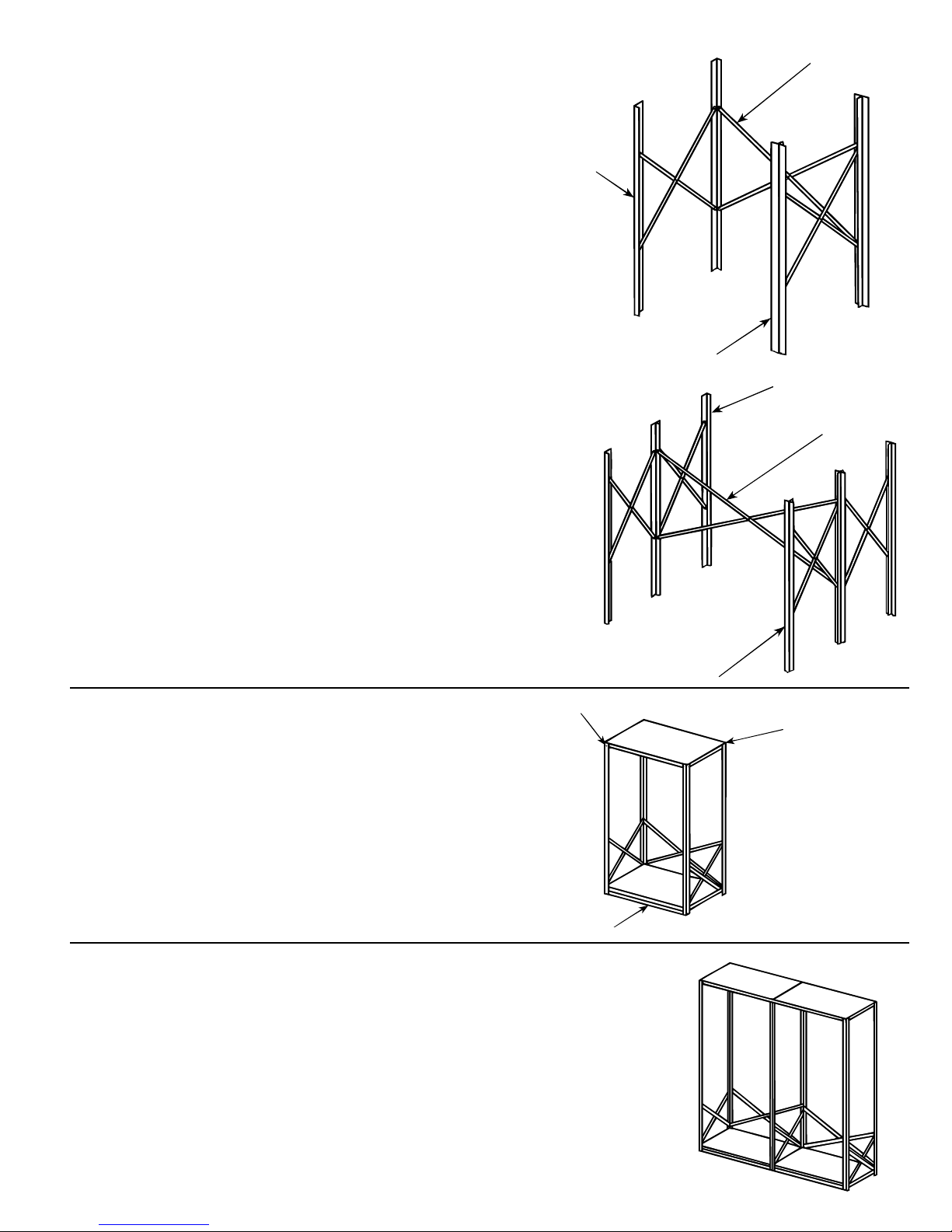
STEP 4 SINGLE ROW - SINGLE FACE
ASSEMBLY
In assembly of a single row - single face, begin with a row end upright assembly, a back sway brace and an intermediate upright assembly. The brace bolts
to the row end and the intermediate at the same level and spacing as the
previously installed side braces. (Steps 2 and 3). The brace bolts on the inside
of the short flange.
DO NOT TIGHTEN BOLTS!
Back Sway Brace
Row End
Assembly
Intermediate Assembly
Row End Assembly
STEP 4A DOUBLE ROW - DOUBLE FACE
ASSEMBLY
In assembly of a double row - double face, begin with two row end upright
assemblies, a back sway brace and two intermediate upright assemblies. Bolt
the two row ends together and then bolt the two intermediates together - each
in the fourth hole from the ends. Two legs of the back brace are now bolted on
the inside of the short flanges of each upright at the same level and spacing as
the previously installed side braces. (Steps 2 and 3).
DO NOT TIGHTEN BOLTS!
Bolt
STEP 5 BASE STRIP ATTACHMENT
If a base strip is used, bolt it into place behind the front of the upright assemblies, as shown. The four bottom shelf clips are hung and the bottom shelf is
set in place. The top shelf should now be installed using clips in the back and
bolts through the front face of the upright and shelf. If a base strip is not used,
install bottom shelf in same manner as top shelf.
NOTE: ONE FACE EDGE OF SHELF IS PLAIN (UNPUNCHED) FOR
AESTHETICS AND ONE FACE EDGE IS PUNCHED TO ACCEPT FULLWIDTH SHELF LABEL HOLDERS.
Base Strip
Back Sway Brace
Intermediate Assembly
Shelf Clip
STEP 6 ROW ASSEMBLY
Continue adding intermediate upright assemblies and back sway braces until
row is complete, finishing off row with a row end upright assembly. Add the
base strips, if used, and as in Step 5, the top and bottom shelves to each
section.
- 5 -
Page 6
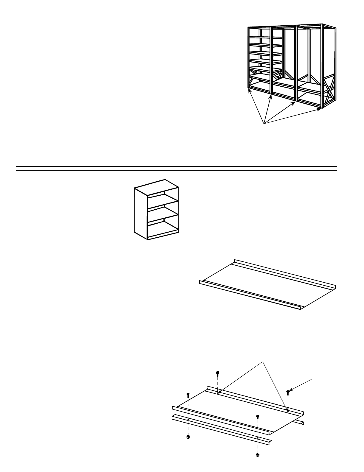
STEP 7 SECTION LEVELING
When required, level sections with shims to cause each upright assembly to be
plum within 1/10 inch per foot of height, up to and including 10' high units. For
units higher than 10', maximum out-of-plumbness should not exceed 1".
FAILURE TO LEVEL SECTION COULD RESULT IN
SHELVING COLLAPSE, PERSONAL INJURY
AND/OR COMMODITY LOSS.
STEP 8 TIGHTEN ALL BOLTS
Tighten all bolts and add the intermediate shelves to complete the sections.
CLOSED TYPE SHELVING
Shims - Front and/or Rear
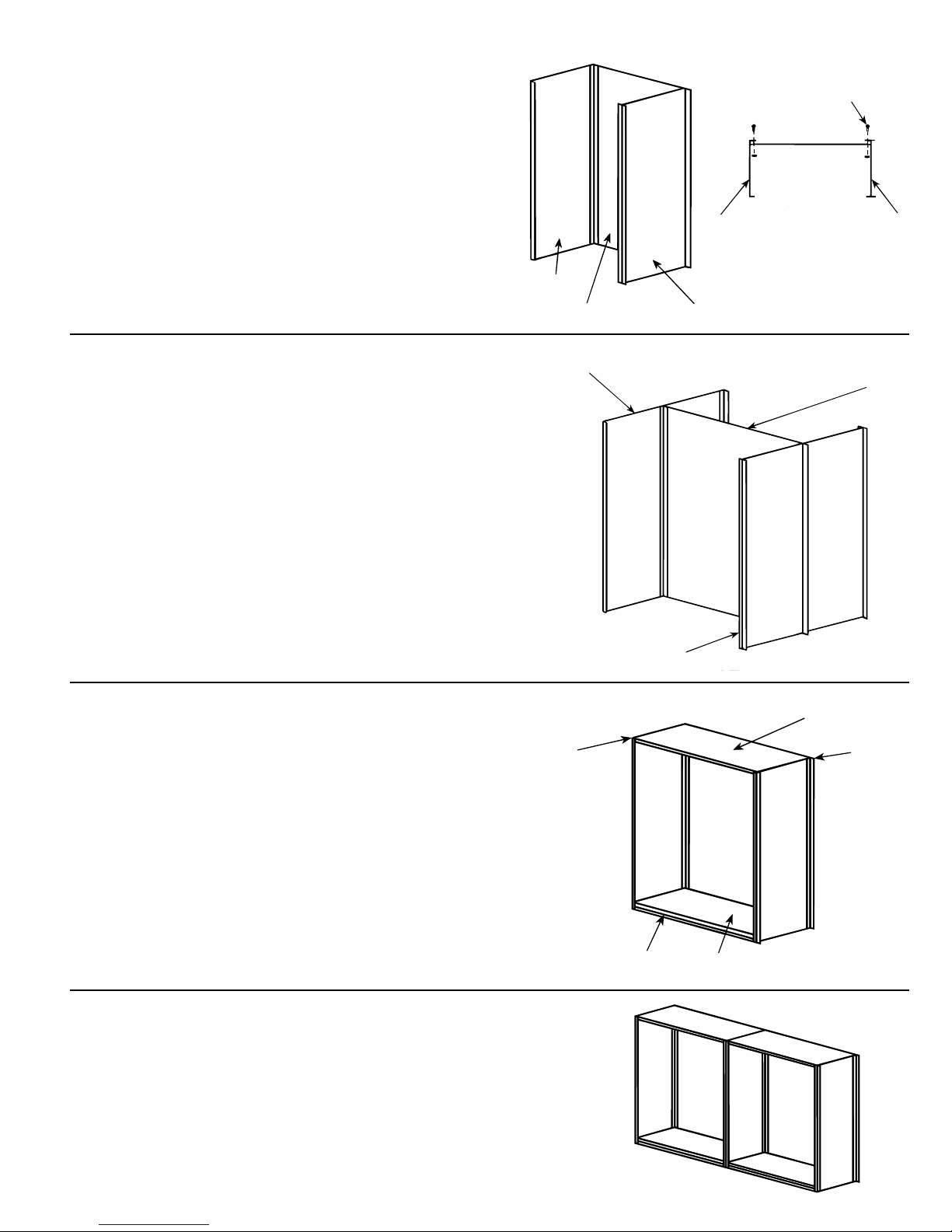
STEP 1 ROW END - CLOSED UPRIGHT
ASSEMBLIES
After the material has been distributed to the proper location, determine from
the floor plan how many row end - closed upright assemblies and intermediate
- closed upright assemblies will be required. The row ends exist as received,
two angle posts welded to a side panel. Set aside the required amount.
STEP 2 INTERMEDIATE - CLOSE UPRIGHT
ASSEMBLY
Assemble the intermediate - closed upright assemblies by bolting two* angle
posts to the closed upright assemblies to form a T (bolt through the fourth hole
from each end). Repeat this procedure until all intermediates are assembled.
*One angle post is required when a beaded post - closed side is being used.
Fourth Hole From Each End
1/4-20 x 5/8
Hex Head
Cap Screw
(Grade 5)
and Hex Nut
- 6 -
Page 7
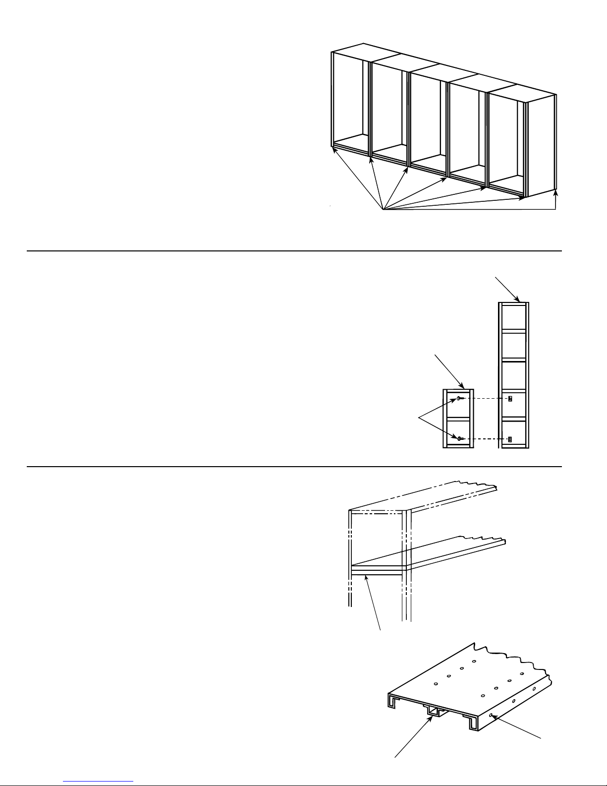
STEP 3 SINGLE ROW - SINGLE FACE
ASSEMBLY
In assembly of a single row - single face, begin with a row end - closed upright
assembly, a back and an intermediate - closed upright assembly. The back
bolts inside the angle post flanges, on both the row end and the intermediate,
at the fourth hole from each end and at two medial* points.
1/4-20 x 5/8 Hex Head
Cap Screw (Grade 5)
and Hex Nut
DO NOT TIGHTEN BOLTS!
*Pre-determine critical shelf location to avoid interference with back bolts.
STEP 3A DOUBLE ROW - DOUBLE FACE
ASSEMBLY
In assembly of a double row - double face, begin with two row end - closed
upright assemblies, a back and two intermediate - closed upright assemblies.
Bolt one side of the back between the angle post flanges of the row ends and
the other side between the angle post flanges of the intermediates. In both
instances, bolt through the fourth hole from each end and at two medial*
positions.
DO NOT TIGHTEN BOLTS.
*Pre-determine critical shelf locations to avoid interference with back bolts.
Row End
Back
Row End
Intermediate
Row End
Intermediate
Intermediate
Back
STEP 4 BASE STRIP ATTACHMENT
If a base strip is used, bolt it into place behind the front flanges of the upright
assemblies, as shown. The four bottom shelf clips are hung and the bottom
shelf is set in place. The top shelf should now be installed using clips in the
back and bolts through the front face of the upright and shelf. If a base strip is
not used, bolt the bottom shelf in place.
NOTE: ONE FACE EDGE OF SHELF IS PLAIN (UNPUNCHED) FOR
AESTHETICS AND ONE FACE EDGE IS PUNCHED TO ACCEPT FULLWIDTH SHELF LABEL HOLDERS.
STEP 5 ROW ASSEMBLY
Continue adding intermediate - closed upright assemblies and backs until row
is complete, finishing off row with a row end - closed upright assembly. Add the
base strips, if used, and the top and bottom shelves to each section.
Bolt
Base Strip
Top Shelf
Shelf Clip
Bottom Shelf
- 7 -
Page 8
STEP 6 SECTION LEVELING
Where required, level sections with shims to cause each upright assembly to
be plum within 1/10" inch per foot of height.
FAILURE TO LEVEL SECTIONS COULD RESULT IN
SHELVING COLLAPSE, PERSONAL INJURY
AND/OR COMMODITY LOSS.
STEP 7 TIGHTEN ALL BOLTS
Tighten all bolts and add the intermediate shelves to complete the sections.
MAJOR ACCESSORIES
LEDGE TYPE SHELVING
Ledge sections, 3'3" high, are bolted to the front of a full height section. The
bolts are fastened through the fourth hole from each end.
Shims
Front and/or Rear
Full Height Section
Ledge Section
Bolt Through Fourth Hole
with 1/4-20 x 5/8 Hex Head
Cap Screw (Grade 5) and
Hex Nut
SHELF SIDE SUPPORTS
Tabs hook into front and rear posts in the same manner as shelf clips. Side
flange of shelf rests on top flange of shelf side support.
SHELF REINFORCEMENT SADDLES
Install under center of shelf, flanged side up. Turn slightly to clear shelf side
flange and then rest on side flanges. Must be used in conjunction with shelf
side supports.
- 8 -
Shelf Side Support
Saddle
Holes
Must
Align
Page 9
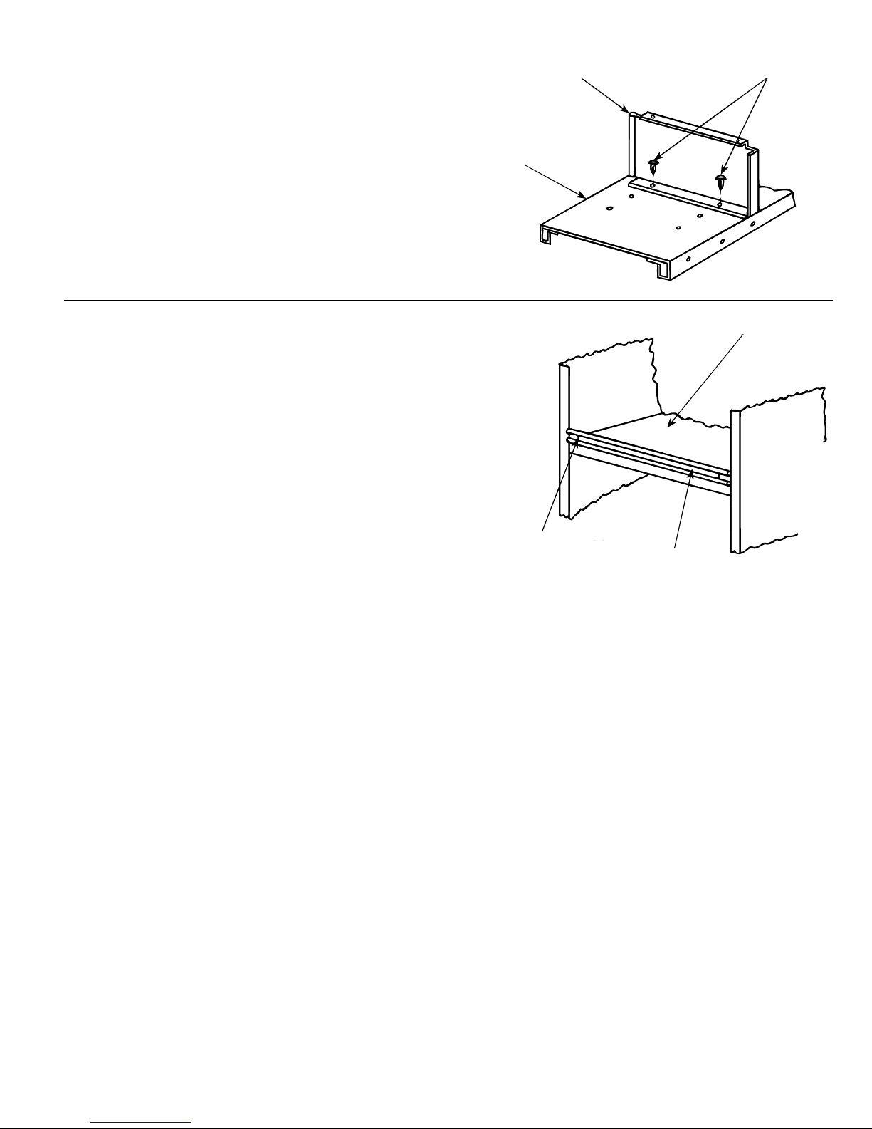
SHELF DIVIDERS - FULL HEIGHT
Install beaded edge toward front. Fasten in place with a snap fastener through
hole in divider flange and hole in shelf, both top and bottom. When one divider
is installed directly above or directly below another divider, one fastener per
hole will hold both dividers.
BIN FRONTS and CLIPS
Install behind front flange of posts.
1-1/2" high bin fronts are supplied with clips which slide behind beads and hook
over post flange.
3" and 6" high bin fronts are generally bolted to post front flange (hardware
furnished) or, optional bolt-on clips may be used.
Beaded Edge
Front
Snap Fastener
Shelf
Clip or 1/4-20 x 5/8
Hex Head Cap
Screw (Grade 5) and
Hex Nut
Bin Front
- 9 -
Page 10
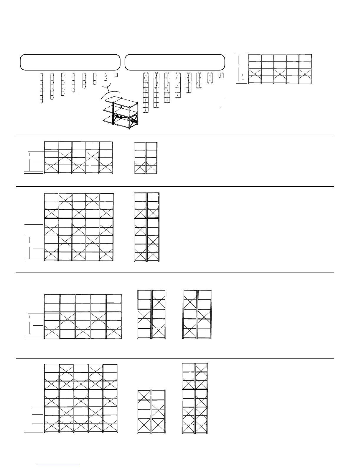
SWAY BRACING RECOMMENDATIONS
FOR UNITS 99" HIGH and LESS
No. Units 8765 4321
No. Braces 10 9 8 7 6543
✖
✖
✖
✖
✖
✖
✖
✖
✖
✖
➛
60
➛
d
➛
➛
➛
30
➛
➛
➛
30
Single Row
✖
✖
✖
✖
✖
✖
✖
✖
✖
✖
✖
✖
✖
✖
✖
✖
✖
✖
✖
✖
✖
✖
✖
✖
✖✖
✖
✖
✖
✖
✖
✖
✖
✖
✖
✖
✖
✖
✖
✖
Fig. 1
Fig. 4
Back Brace
No. Units 16 14 12 10 8642
No. Braces 16 14 13 11 10 8 6 3
✖
✖
✖
➛
M
➛
d
➛
➛
➛
30
➛
Fig. 5
Back Brace
Double Row
✖✖
✖✖
✖✖
✖
✖
✖
✖
✖
✖
✖
✖
✖
✖
✖
✖
✖
✖
✖
✖
✖
✖
✖
✖
✖
✖✖
✖
✖
✖
NOTE:
FOR CRITICAL SHELF LOCATIONS, MINOR CHANGES
TO THESE RECOMMENDATIONS ARE ACCEPTABLE.
Fig. 4A
Side Brace
✖✖
✖✖
✖
✖
✖
✖
✖
✖
✖
✖
✖
✖
✖
✖
✖
✖
✖✖
✖
✖
✖
✖
✖
✖
✖✖
Fig. 2
✖
✖
✖
✖
✖
✖
✖
✖✖
✖
Connection point as close as possible to mezzanine level- may be either above or below level.
M = maximum distance possible - up to and including 30"
d = minimum reasonable distance (e.g. 4.5" - 6.0")
Fig. 5A
Side Brace
➛
H
✖
✖
✖
✖
✖
✖✖
✖
✖
✖
H
➛
3
Fig. 3
Back Brace
✖
Light Loading
Both single and double rows may use sway braces as in
Figures 1 and 2. The end and back of the first and last
section of each row always contains a sway brace. Every
other intermediate and every other back should contain a
sway brace. The height location of the sway brace is
determined as in Figure 3, where the center line of the
cross is "height divider by 3" up from the bottom.
Standard Loading
For rigidity in standard duty applications, a pair of sway
braces should be put in every opening at the heights
illustrated in Figure 4. Each open end should be braced as
illustrated in Figure 4A.
Multi-level Application
For rigidity in mezzanine applications, two sway braces
should be put in every other opening at the heights
illustrated in Figure 5. The intervening openings should be
braced with one pair of sway braces as shown. The term
"d" equals the distance for mounting the sway braces to the
post from the floor. Bolt the front of the center shelf and the
front of the top shelf and the base strip in place. The open
ends should be braced as illustrated in Figure 5A.
FOR UNITS OVER 99" HIGH
Light Loading
For rigidity, Borroughs recommends that one pair of sway
braces be installed in each open end and open back.
Sway brace height is as shown in Figure 6. Figure 6A and
➛
60
➛
30
d
➛
➛
➛
➛
NOTE:
FOR CRITICAL SHELF LOCATIONS, MINOR CHANGES TO THESE RECOMMENDATIONS ARE ACCEPTABLE.
Fig. 6
Back Brace
Fig. 6A
Side Brace
Fig. 6B
Side Brace
Connection point as close as possible to mezzanine levelmay be either above or below level.
M = maximum distance possible - up to and including 30"
d = minimum reasonable distance (e.g. 4.5" - 6.0")
➛
➛
30
➛
➛
M
d
➛
➛
➛
30
➛
PLEASE NOTE: FAILURE TO FOLLOW THESE SWAY BRACING RECOMMENDATIONS COULD RESULT IN AN IMPROPER INSTALLATION, SHELVING COLLAPSE, PERSONAL INJURY AND/OR COMMODITY LOSS.
Fig. 7
Back Brace
Fig. 7A
Side Brace
- 10 -
Fig. 7B
Side Brace
6B are an end and an intermediate, respectively. The
bracing patterns are opposite each other and should
alternate from one end of a row down to the other end.
Pre-assembly of the two uprights is identical.
Standard Loading and Multi-level
For rigidity, Borroughs recommends that sway braces be
used in open backs as illustrated in Figure 7. Sway brace
height is as shown in Figure 7. Bolt the front of the center
shelf and the front of the top shelf and the base strip in
place. Sway bracing for the ends of sections should be
installed as shown in Figure 7A for heavy-duty and Figure
7B for multi-level applications.
Page 11

HARDWARE REQUIREMENTS
Part Name Hardware Included Req'd.
Pieces
Angle Post 1/4-20 x 5/8 HHMS Gr. 5 2
Std. & Commercial 1/4-20 Hex Nut 2
Beaded Post None -
Closed Side 1/4-20 x 5/8 HHMS Gr. 5 4
Angle Post 1/4-20 Hex Nut 4
Closed Side None -
Beaded Post
Post Splicer 1/4-20 x 3/4 HHMS Gr. 5 4
1/4-20 x 5/8 HHMS Gr. 5 4
1/4-20 Hex Nut 8
Post Splicer Bar 1/4-20 x 5/8 HHMS Gr. 5 6
1/4-20 Keps Nut 6
Post Splicer Plate 1/4-20 x 5/8 HHMS Gr. 5 8
1/4-20 Keps Nut 8
Beaded Post 1/4-20 Keps Nut 4
Splice Kit 1/4-20 x 5/8 HHMS Gr. 5 4
10-24 x 1/2 Rolok Screw 8
Splicer Bar 1
Beaded Post Splicer 1
Foot Plate Kits
Front Foot 1/4-20 Keps Nut 1
and Back-to-Back 1/4-20 x 5/8 HHMS Gr. 5 1
Plate
Shim Plates
Front None -
Back None -
Post Foot Plate None -
Post Foot Angle 1/4-20 x 5/8 HHMS Gr. 5 2
1/4-20 Hex Nut 2
Part Name Hardware Included Req'd.
Pieces
Shelf Divider Divider Clip (nylon) 2
Angle (14761-000)
Shelf Divider Divider Clip (nylon) 4
Fixed (14761-000) Up to 24" deep
36" deep 6
Shelf Divider None -
Support
Label Holder Divider Clip (nylon) 3
Full Length (14761-000)
Long Parts Frame Hardware Pack #334 includes:
1/4-20 x 1 Slotted THMS 4
1/4-20 Hex Nut 4
5/15-18 x 5/8 Hex Head
Cap Screw 4
5/16-18 Square Nut 4
5/16 Shakeproof Washers 4
Spacer Rods None -
Boltless Hang Rods None -
Shelf Box None -
Box Guide 1/4-20 x 5/8 HHMS Gr. 5 2
1/4-20 Hex Nut 2
Bin Front Bin Front Clip Plated 2
1-1/2" Angle Post 1/4-20 x 5/8 HHMS Gr. 5 2
1/4-20 Hex Nut 2
Bin Front 1/4-20 x 1 Slotted THMS 2
3" & 6" Angle Post 1/4-20 Hex Nut 2
Bin Front 1/4-20 x 5/8 HHMS Gr. 5 2
1-1/2", 3" & 6" 1/4-20 Hex Nut 2
Beaded Post
Part Name Hardware Included Req'd.
Pieces
Sliding Door Hardware Pack #48 includes:
Door Pulls (Plated) 2
Furniture Lock (Plated) 1
Lock Catch (Painted) 1
Ball Bearing Sheave 4
10-24 Hex Nut 8
1/4-20 Hex Nut 14
10-24 x 3/8 Phillips THMS 8
#8 x 3/8 Slotted Oval Head
Screw 4
1/4" Lock Washer Fin. P. 14
1/4-20 x 5/8 THMS 14
Instructions 1
Mezzanine Beam None -
Mezzanine Bracket 1/4-20 x 1 HHMS Gr. 5 5
Angle & Beaded 1/4-20 Keps Nut 5
Catwalk Beams 1/4-20 Keps Nut 4
Angle & Beaded 1/4-20 x 1 HHMS Gr. 5 4
Face Aisle 1/4-20 Keps Nut 2
Cap Beam 1/4-20 x 3" Hex Head Cap
Screw 2
Cross Aisle None -
Cap Beam
Outside Aisle 1/4-20 Keps Nut 2
Cap Beam 1/4-20 x 3" Hex Head Cap
Screw 2
Single Face 1/4-20 Keps Nut 1
Back Cap 1/4-20 x 3" Hex Head Cap
Screw 1
Back-to-Back Cap 1/4-20 Keps Nut 2
1/4-20 x 3" Hex Head Cap
Screw 2
Post Cover 10-24 Hex Nut 6
Back Back Clip (05088-824-330) .25
1/4-20 x 5/8 Gr. 5 HHMS 10
1/4-20 Hex Nut 10
Back Brace (pair) 1/4-20 x 5/8 HHMS 5
1/4-20 Hex Nut 5
Side Brace (pair) 1/4-20 x 3/4 HHMS Gr. 5 5
1/4-20 Hex Nut 5
Face Brace 1/4-20 x 5/8 HHMS Gr. 5 6
Angle & Beaded Post 1/4-20 x 3/8" Self-Drilling MS 6
(pair) 1/4-20 Keps Nut 6
Double Face Tape .075 ft.
Base Strip 1/4-20 x 5/8 HHMS Gr. 5 2
Angle & Beaded 1/4-20 Hex Nut 2
Box Edge Shelves Shelf Brackets 4
(09531-099-330)
Shelf Saddle None -
Shelf Saddle None -
Support - Boltless
(pair)
Shelf Divider None -
Sliding
Bin Front Clip 1/4-20 x 5/8 HHMS Gr. 5 2
3" & 6" 1/4-20 Hex Nut 2
Counter Top None -
Ledge Top None -
Counter Back 1/4-20 x 5/8 HHMS 8
1/4-20 Hex Nut 8
Tape Reel Hanger Hardware Pack #342 includes:
Kit 10-24 Keps Nut 2
10-24 x 3/8 Phillips THMS 2
Print-out Hanger Hardware Pack #342 includes:
10-24 Keps Nut 2
10-24 x 3/8 Phillips THMS 2
Single Point Hanger None -
Framed Swing Hardware Pack #414 includes:
Door Handle with Lock and 2 Keys 1
Push Clip (11914-028) 1
Handle Reinforcement 1
Cam Ind. Double Door 1
1/4-20 x 5/8 HHMS 6
1/4-20 Hex Nut 6
Saddle Reinforcement 1
#8-32 x 5/16 Sems Screw 2
- 11 -
Single Face 1/4-20 Keps Nut 2
Attachment Bracket 1/4-20 x 5/8 Hex Head Cap
Screw 2
Row End Corner 1/4-20 Keps Nut 3
Splice Channel 1/4-20 x 1-1/4" HHMS Gr. 5 3
Row End 1/4-20 Keps Nut 4
Kick Plate 1/4-20 x 1-1/2" Hex Head Cap
Screw 4
Row End 1/4-20 Keps Nut 3
Hand Rail 1/4-20 x 3/4" THMS 3
Citation 0612 Hardware Pack #251 includes:
1/4-20 Hex Nut 21
Shelf Brackets 12
1/4-20 x 5/8 PHMS 21
Citation 0618 Same as Citation 0612
Page 12
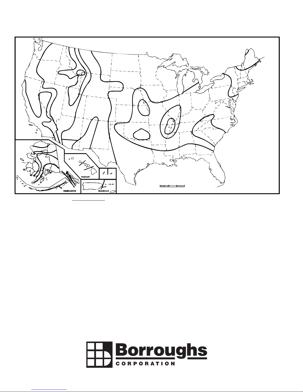
SEISMIC RISK MAP
2A
1
2A
ALASKA
1
ALEUTIAN
ISLANDS
2B
3
4
3
4
3
4
0
1
2B
3
2B
1
4
2B
2B
3
2A
KAUAI
3
4
0 100 200
MILES
3
3
3
1
OAHU
300
2B
2B
4
2B
0
1
MILES
1
1
1
2B
MAUI
HAWAII
3
100
3
PUERTO RICO
0
GUAM
25 50
MILES
1
3
TUTUILA
0
0
0
1
2A
2A
2A
3
1
2A
1
0
0
3
4
0
100
200 300
MILES
0
Reproduced from the 1997 edition of the Uniform Building Code™, copyright© 1997, with the permission of the publisher, the International Conference of Building Officials.
ICBO and Borroughs assume no responsibility for the accuracy or the completion of summaries provided herein.
All areas of the United States have been zoned seismically. Each zone indicates the anticipated intensity or severity of a seismic occurrence within
that region. Zones range from 0 (least likely) to 4 (most likely) to experience damage.
NOTE: Special care should be taken when specifying any system in a highly seismic area.
3002 N. BURDICK STREET KALAMAZOO, MI 49004-3483
800-748-0227 FAX: 269-342-4161 www.borroughs.com
- 12 -
 Loading...