

Page 1
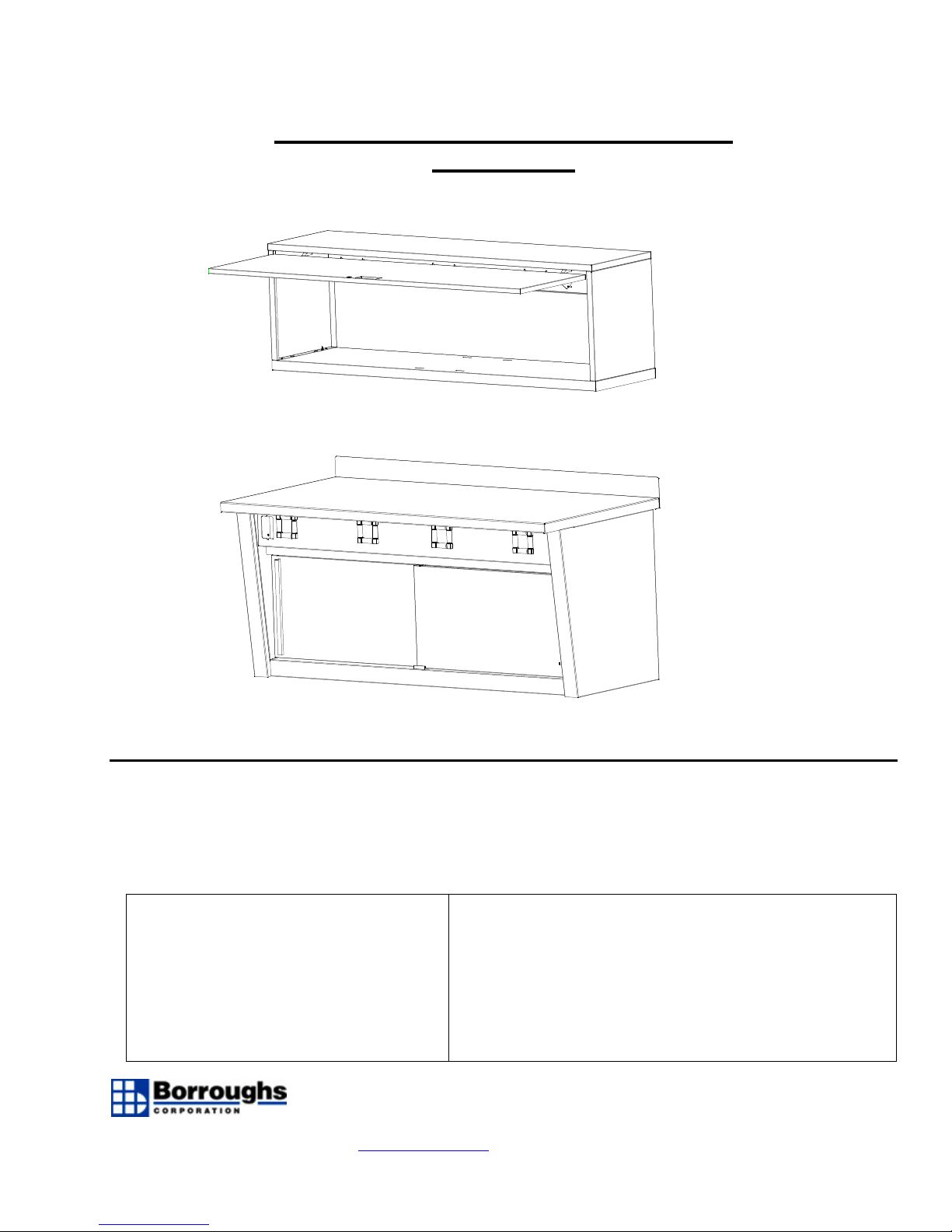
BASIC PRO-SERIES WORKBENCH
property damage.
SECTION #1
CONTENTS
Basic Pro-Series…………………………………………2
Roller Bearings………………………………………….11
Lift Cabinet……………………………………………...12
Continuous Pro-Series…………………..……… ….…14
IMPORTANT - PRODUCT LIABILITY
INFORMATION Read all instructions before
proceeding with installation. Vital product
information pertaining to proper set-up and
cautions are included. Failure to follow these
instructions may result in personal injury and/or
RETAIN THIS MANUAL FOR FUTURE
REFERENCE
NOTICE:
year limited warranty against manufacturing defects in material and workmanship. If a Borroughs
product fails to perform because of a manufacturing defect, Borroughs will examine it. If found
defective, it will be repaired at our option. This warranty applies only to Borroughs products acquired
directly from Borroughs Corporation or from Authorized Borroughs Dealers. This warranty does not
apply to any product which has been subject to misuse, negligence, or accident; has been damaged in
unauthorized persons or been repaired with non-standard Borroughs replacement parts. This warranty
specifically excludes claims for indirect, incidental, or consequential damages arising in any way from a
product defect. This warranty is exclusive, and exists in lieu of all other warranties, either express or
implied. This warranty gives you specific legal rights; you may also have other rights which may vary
from state to state. To obtain warranty service, contact your Borroughs Selling Dealer. You must make
a written claim. Provide a copy of your purchase record and a written description of the warranty
problem with your claim. If you are unable to contact your dealer, contact: Borroughs Corporation,
3002 N. BURDICK ST. ▪ KALAMAZOO, MI 49004-3483 09-50679-00
800-748-0227 ▪ FAX: 269-342-4161 ▪ www.borroughs.com November 2004
1
Borroughs Corporation extends to the original purchaser from the date of purchase, a 5
shipment, storage, or installation; has been misapplied or has been modified or repaired by
Customer Service Manager, 3002 N. Burdick Street, Kalamazoo, MI 49004-3483
Page 2
FOR STEPS 1-3, HARDWARE NEED ONLY BE FINGERTIGHTENED
TOOLS REQUIRED: PHILLIPS HEAD SCREWDRIVER, ADJ WRENCH, FLAT HEAD SCREWDRIVER, CORDLESS
DRIVER WITH PHILLIPS ATTACHMENT, TAPE MEASURE
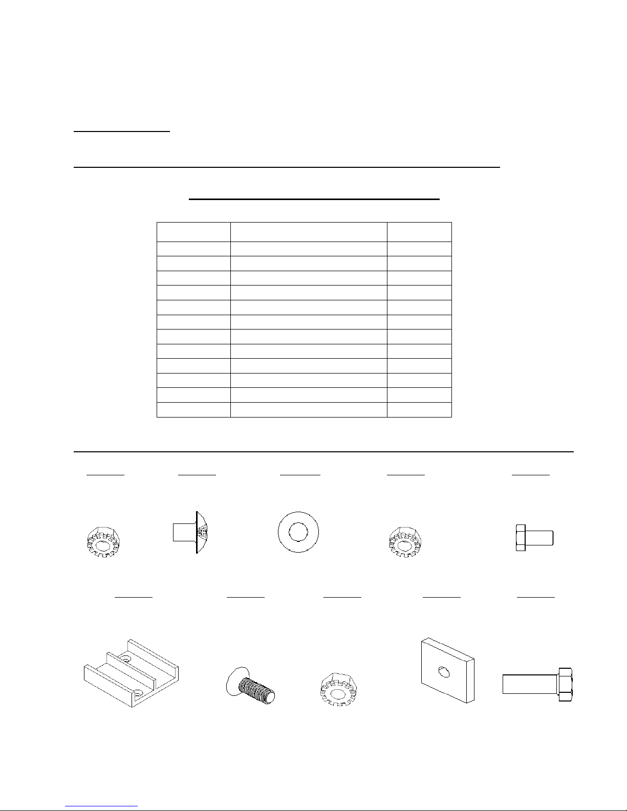
*REMOVE ALL ITEMS FROM CARTON AND CHECK AGAINST THE FOLLOWING LIST:
*PARTS LIST – BASIC UNIT*
ITEM DESCRIPTION REQ’D
1 BENCH TOP 1
2 LH LEG NO HOLES 1
3 RH LEG NO HOLES 1
4 LH LEG FILLER 1
5 RH LEG FILLER 1
6 BASE SHELF 1
7 BACK STOP CHNLS 1
8 BENCH DOORS 2
9 DOOR TRACK 1
10 TRACK COVER 1
11 BACKSPLASHES 1
12 FRONT FACE BRKT 1
*REMOVE ALL ITEMS FROM THE HARDWARE PACK AND CHECK AGAINST THE FOLLOWING LIST:
ITEM 13 ITEM 14 ITEM 15 ITEM 16 ITEM 17
10-24 KEPS NUT PNHD TH 10-24 x 3/8 ¼ FLAT WASHER ¼-20 KEPS NUT ¼-20X5/8 GD5 HX HD
SCREW
(3) REQ’D (3) REQ’D (24) REQ’D (12) REQ’D (12) REQ’D
DBLE CHNL DOOR GUIDE 8-32 x ¾ FLHD MS KEPS NUT 8-32 1-5/8 X 1-5/8 SQ WASHER 3/8-16 X1-1/4 BOLT
(1) REQ’D (2) REQ’D (2) REQ’D (4) REQ’D (4) REQ’D
ITEM 18 ITEM 19 ITEM 20 ITEM 21 ITEM 22
2
Page 3
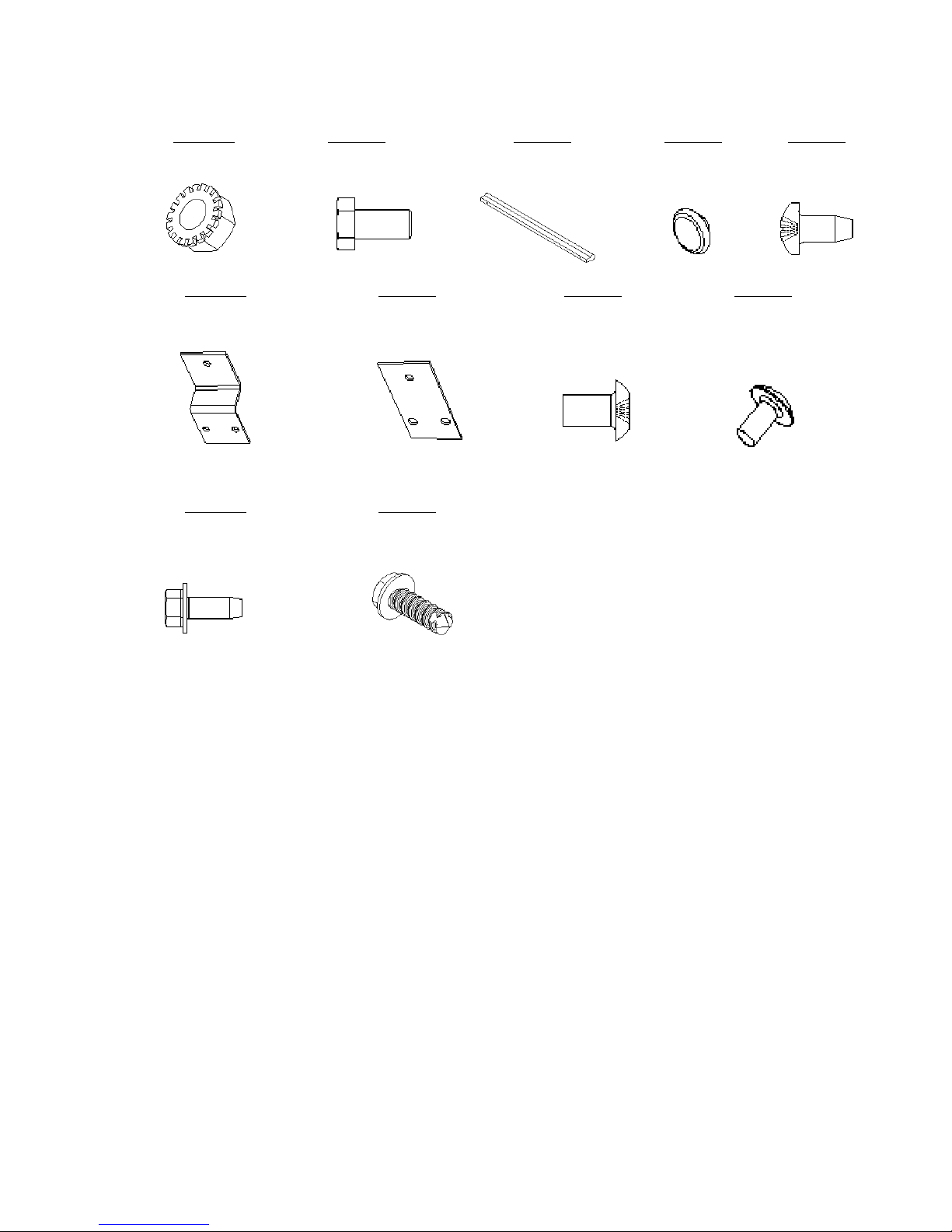
ITEM 23 ITEM 24 ITEM 25 ITEM 26 ITEM 27
5/16-18 KEPS NUT 5/16-18 X 5/8 HXHD BOLT DOOR HANDLE 15IN ROLLER WHEEL 10-24 ROLOK
(12) REQ’D (12) REQ’D (2) REQ’D (4) REQ’D (12) REQ’D
ITEM 28 ITEM 29 ITEM 30 ITEM 31
5/8 OFFSET WHEEL BRKT STRAIGHT WHEEL BRKT M4-.7 X 8MM TRHD 8-32 X 5/16 PNHD PHIL
(2) REQ’D (2) REQ’D (4) REQ’D (4) REQ’D
ITEM 32 ITEM 33
¼-20 x ¾ Hes Head SFS #14 x ¾ Hex Head SDS
(4) REQ’D (1) REQ’D
3
Page 4
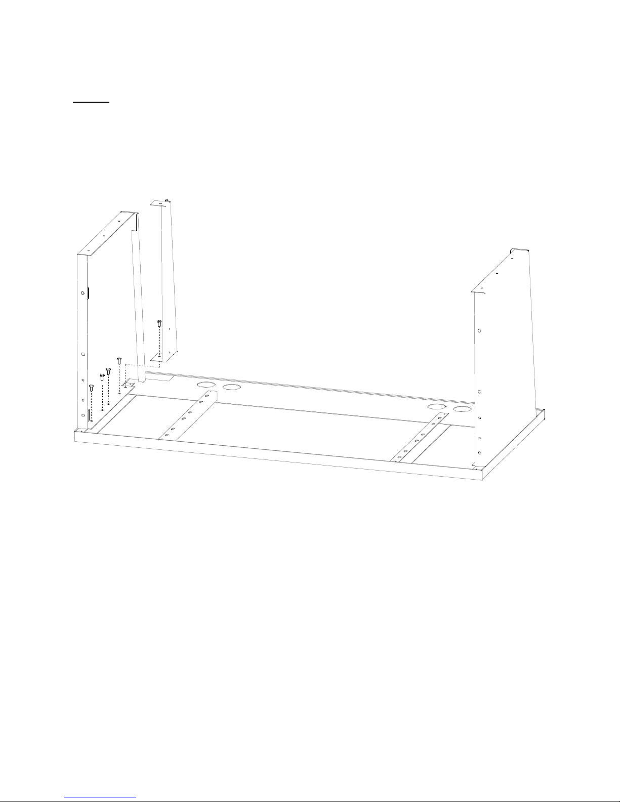
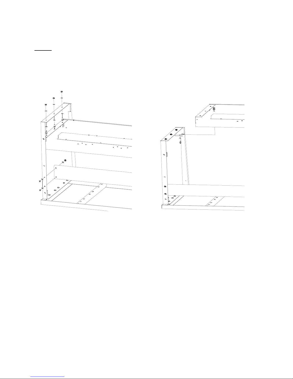
STEP 1: LEG ASSEMBLY
Place a bench top (Item 1) on a flat surface with the four support angles facing up. Fasten LH and RH legs (Items 2 & 3) to
the outside angles using (10) 5/16-18 x 5/8 hex head bolts (Item 24) and (10) 5/16-18 keps nut (Item 23). If your bench has
an overhang then move the leg with holes in 12” to the inside support angle. Do not place bolt in hole closest to front of
bench until leg fillers are in place. Next, place LH and RH leg fillers (Items 4 & 5) to the inside of the legs as shown in
(Figure 1.). Use (1) 5/16-18 x 5/8 cap screw (Item 24) and (1) 5/16-18 keps nut (Item 23) per filler. Do not tighten fasteners.
Figure 1.
4
Page 5
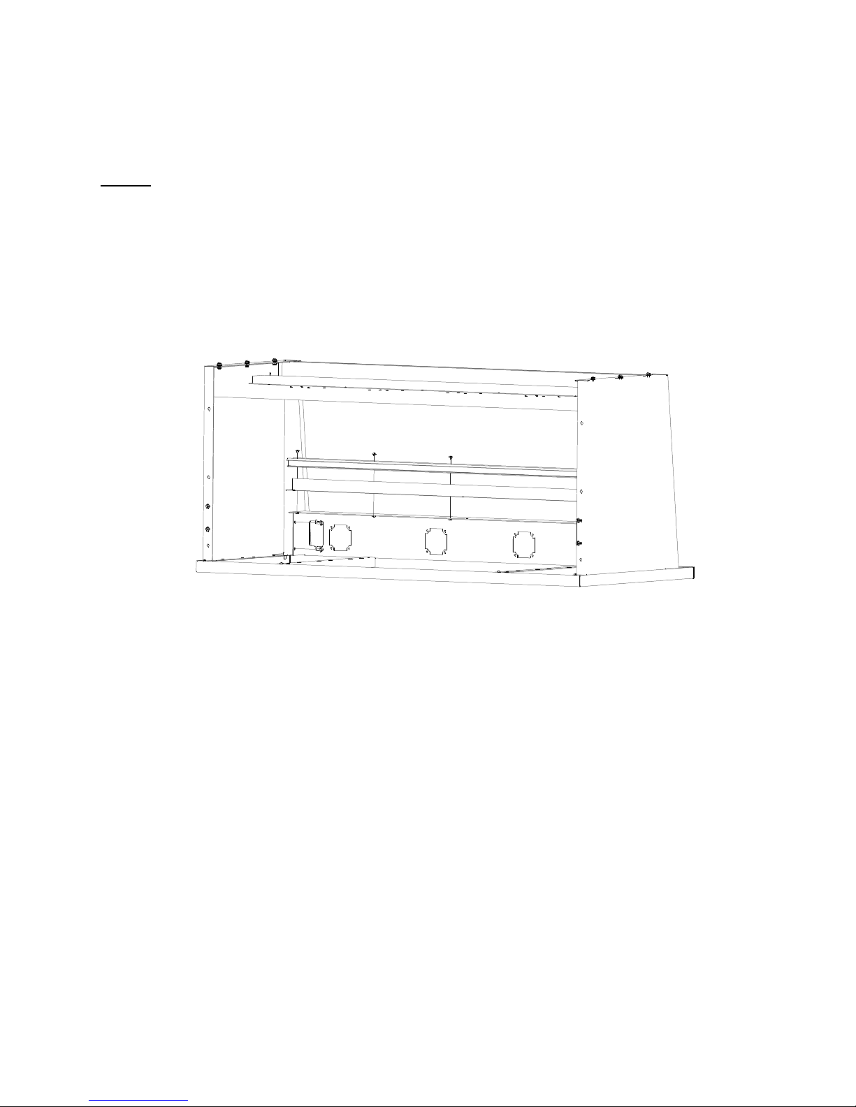
STEP 2: BASE SHELF ASSEMBLY
Place the base shelf (Item 6) between the leg fillers and the leg (Figure 2.) on both sides. Fasten base shelf to legs
and fillers by using (8) ¼-20 x 5/8 cap screws (Item 17), (16) ¼ flat washers (Item 15), & (8) ¼-20 keps nuts (Item
16). Next, position and fasten back stop chnl into place with (4) ¼-20 x 5/8 cap screws (Item 17), (8) ¼ flat washers
(Item 15), & (4) ¼-20 keps nuts (Item 16). Do not tighten
fasteners at this point.
Figure 2.
5
Page 6
IF INSTALLING ROLLER BEARINGS THEN SKIP TO SECTION 2 BEFORE GOING TO STEP 3
STEP 3: FRONT FACE / DOOR TRACK
Place the front face (Item 12) in-between the leg fillers as is shown in (Figure 3). Line up the holes in the leg fillers with the
holes on the ends of the front face and fasten tight with (4) ¼-20 x ¾ hex head TFS (Item 32). Next, fasten the front edge of
the front face to the top using (1) #14x3/4 hex head SDS (Item 33) through the hole in the front face. Place the track cover
(Item 10) on the front face lining up the three holes, then place the track (Item 9) on top of the track cover keeping the three
holes lined up. Using (3) #10-24 x 3/8 Truss Hd Phil (Item 14) and (3) #10-24 keps nut (Item 13) fasten track & track cover
to front face.
Figure 3.
6
Page 7
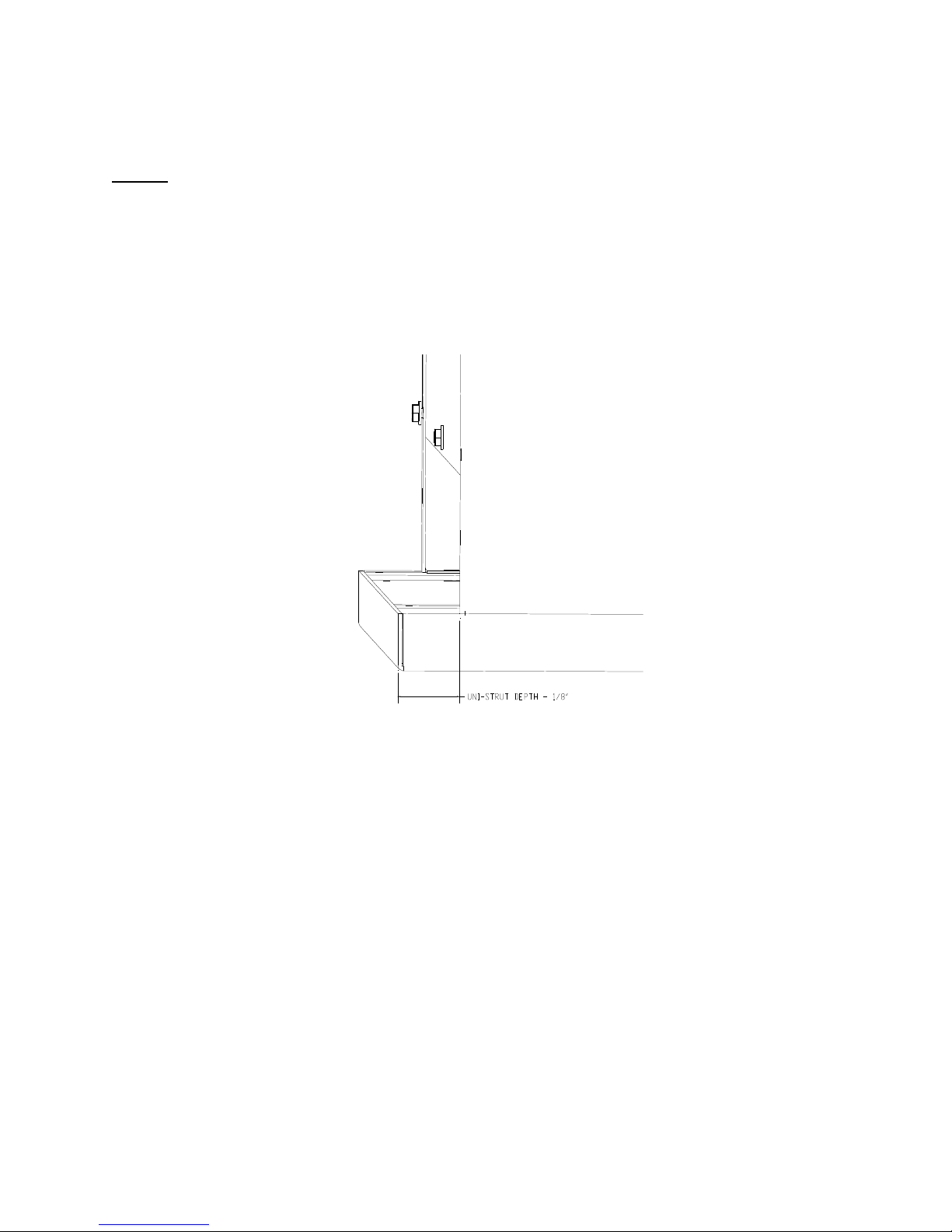
STEP 4: SQUARE AND TIGHTEN
Measure the distance from the back of the leg to the edge of the top. This distance needs to be 1/8” smaller than the depth of
the uni-strut being used to mount unit to the wall (Ex. Set distance to 1-1/2” if using 1-5/8” uni-strut). Next measure the
distance from the outside of the leg to the side edge of the top and make sure they are equal to ensure a square unit. NOTE:
IF BUILDING A 10FT BENCH WITH 24” CENTER SHELF SET DISTANCE FROM OUTSIDE OF LEG TO SIDE
EDGE OF BENCH TO 12-1/16”. Once both legs have been measured and set for square then tighten the (12) 5/16-18 x 5/8
cap screws (Item 24) that attach the top to the legs. Once those have been tightened everything else may be tightened at this
time. See (Figure 4).
Figure 4.
IF INSTALLING LIFT CABINET THEN SKIP TO SECTION 3 BEFORE GOING TO STEP 5
7
Page 8
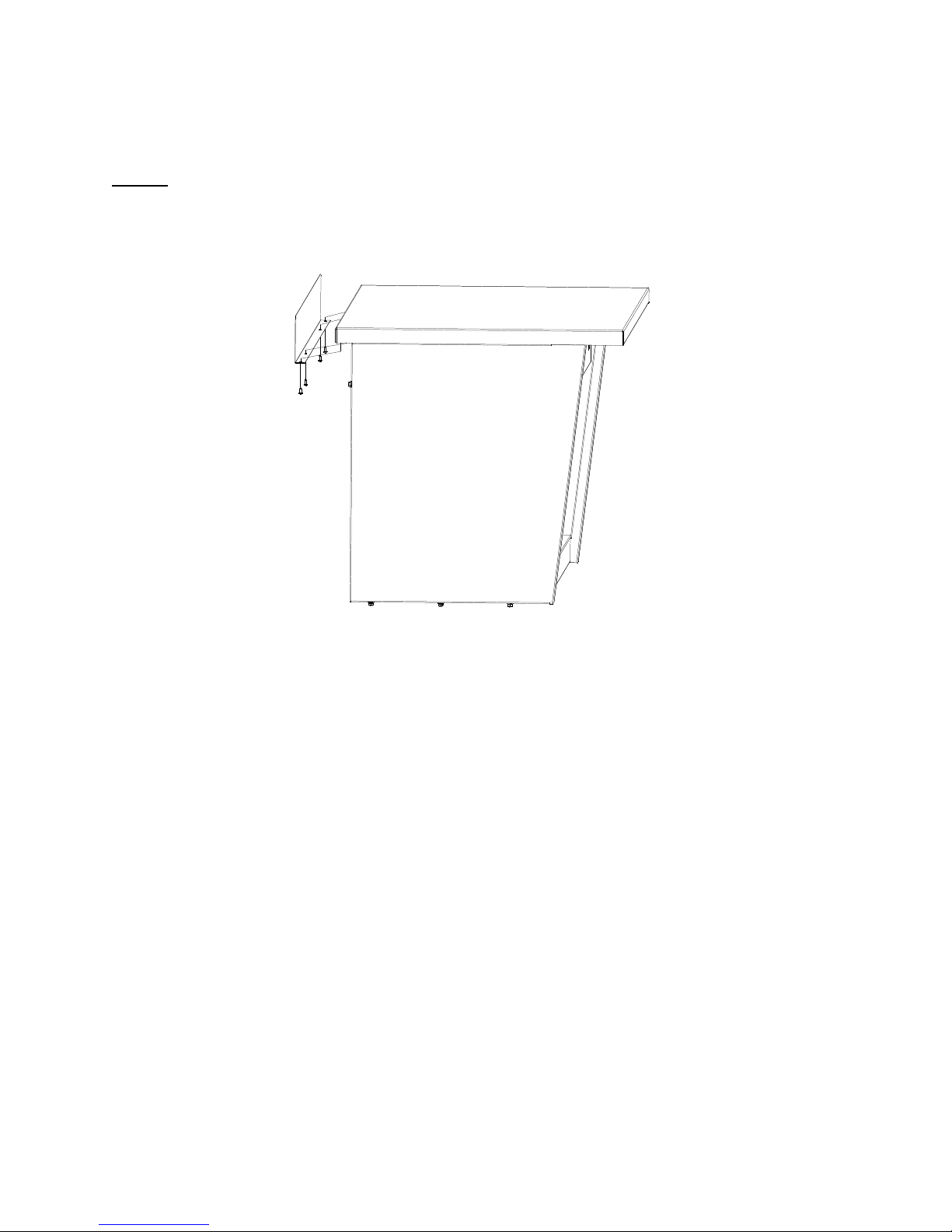
STEP 5: ATTACH BACKSPLASH
Remove protective film from backsplash and fasten to back of bench top using (4) 10-24 rolok screws (Item 27). See (Figure
5).
Figure 5.
8
Page 9
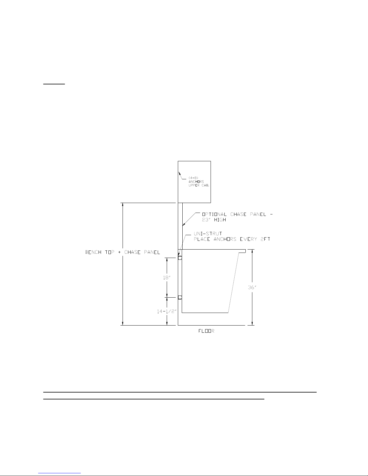
STEP 6: MOUNT TO WALL
Set bench upright on floor. Cut (2) pieces of uni-strut to nominal length of bench. Attach first piece of uni-strut to wall 12”
above the floor. Attach second piece of uni-strut to wall 30” above floor. For proper alignment it’s very important that the
two pieces of uni-strut are mounted 18” center to center. Make sure uni-strut is parallel to floor and parallel to each other.
Place (2) spring loaded uni-strut nuts in the top and bottom uni-strut that will line up with the holes in the legs for mounting.
Using (4) 1-5/8 x 1-5/8 sq washers (Item 21) and (4) 3/8-16 x 1-1/4” cap screws (Item 22) attach unit to wall. Keep fasteners
loose until bench is in desired location and then tighten. See (Figure 6)
NOTE: IF A BENCH TOP HEIGHT OF 36” IS NOT WANTED THEN ADJUST BOTTOM UNI-STRUT
ACCORDLYING BUT KEEP 18” DISTANCE BETWEEN THE TWO UNI-STRUTS
Figure 6.
9
Page 10
IF YOU’RE ASSEMBLING A 2nd PART 10FT WORK BENCH GO TO SECTION #4 BEFORE STARTING STEP
#7
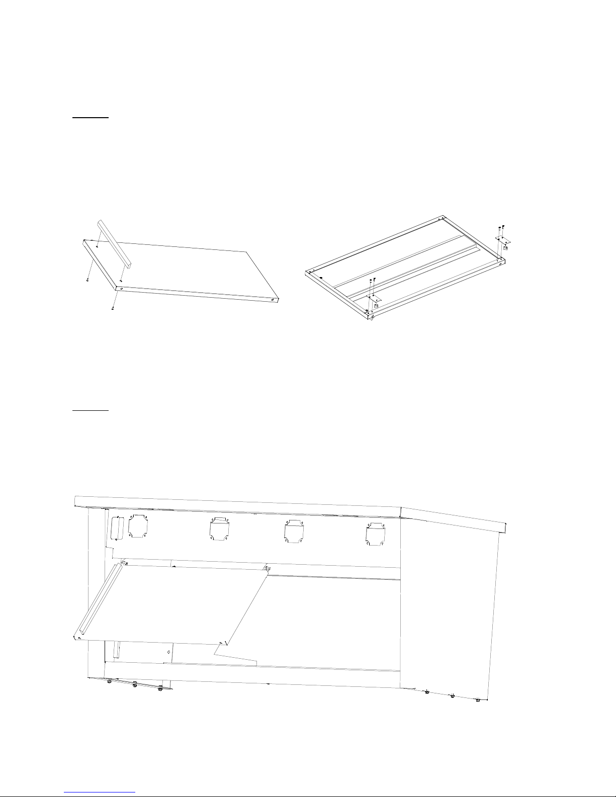
STEP 7: DOOR ASSEMBLY
Attach the handles (Item 25) to the doors using (2) M4-.7 x 8mm phil truss hd screws (Item 30) per door. Fasten (2) 5/8
offset wheel brackets (Item 28) to the front door using (4) 10-24 rolok screws (Item 27), make sure handle is on the right
hand side. Then fasten (2) straight wheel brackets (Item 29) to the back door using (4) 10-24 rolok screws (Item 27), make
sure when brackets are attached that handle is on the left hand side. Assemble (2) roller wheels (Item 26) to each door using
(2) 8-32 x 5/16” pnhd phil screw (Item 31). See (Figure 7).
Figure 7.
STEP 8: MOUNT DOORS
Hang back door first by tilting door outward at bottom and setting on the back track. Then hang the front door by tilting door
outward at the bottom and setting on the front track. Once both doors are hung then push both doors to one side and slide in
(1) double channel door guide (Item 18). Use (2) 8-32 x ¾ flat hd screw (Item 19) and (2) 8-32 keps nut (Item 20) to fasten
door guide. See (Figure 8).
Figure 8.
10
Page 11
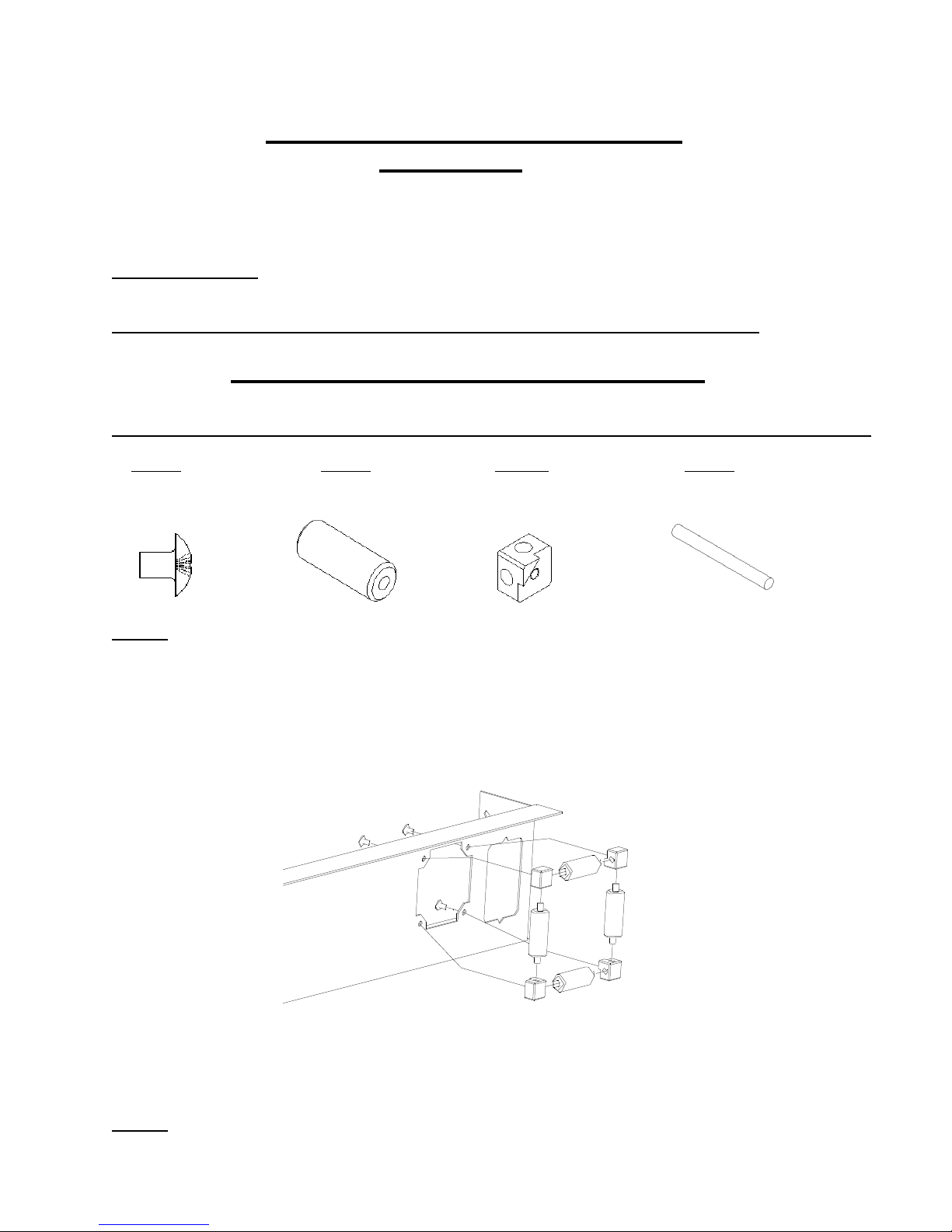
ROLLER BEARING ASSEMBLY
SECTION #2
FOR STEP 1, HARDWARE NEED ONLY BE FINGERTIGHTENED
TOOLS REQUIRED: PHILLIPS HEAD SCREWDRIVER
*REMOVE ALL ITEMS FROM CARTON AND CHECK AGAINST THE FOLLOWING LIST:
*PARTS LIST – ROLLER BEARING*
*REMOVE ALL ITEMS FROM THE HARDWARE PACK AND CHECK AGAINST THE FOLLOWING LIST:
ITEM 1 ITEM 2 ITEM 3 ITEM 4
PNHD TH 10-24 x 1/4 NYLON ROLLER ROLLER GUIDE MTG BLOCK 2-9/16” ROD
(4) REQ’D (4) REQ’D (4) REQ’D (4) REQ’D
STEP 1: ROLLER BEARING ASSEMBLY
Prior to Step 3 in the first section, attach the (4) roller guide mtg blocks (Item 3) to the front face. Use (4) 10-24x1/4 pnhd
screws to attach the mounting blocks, DO NOT TIGHTEN. Slide (1) rod (Item 4) into (1) nylon roller (Item 2) and then
slide the rod into hole in mounting block then slide the other end into the corresponding hole in opposite mounting block.
Make sure that the tabs on the mounting blocks are facing towards the opening. Repeat for all four rollers. See (Figure 9).
Figure 9.
STEP 2: TIGHTEN ROLLER ASSEMBLY
Once all four roller bearings are installed then tighten all four screws.
11
Page 12
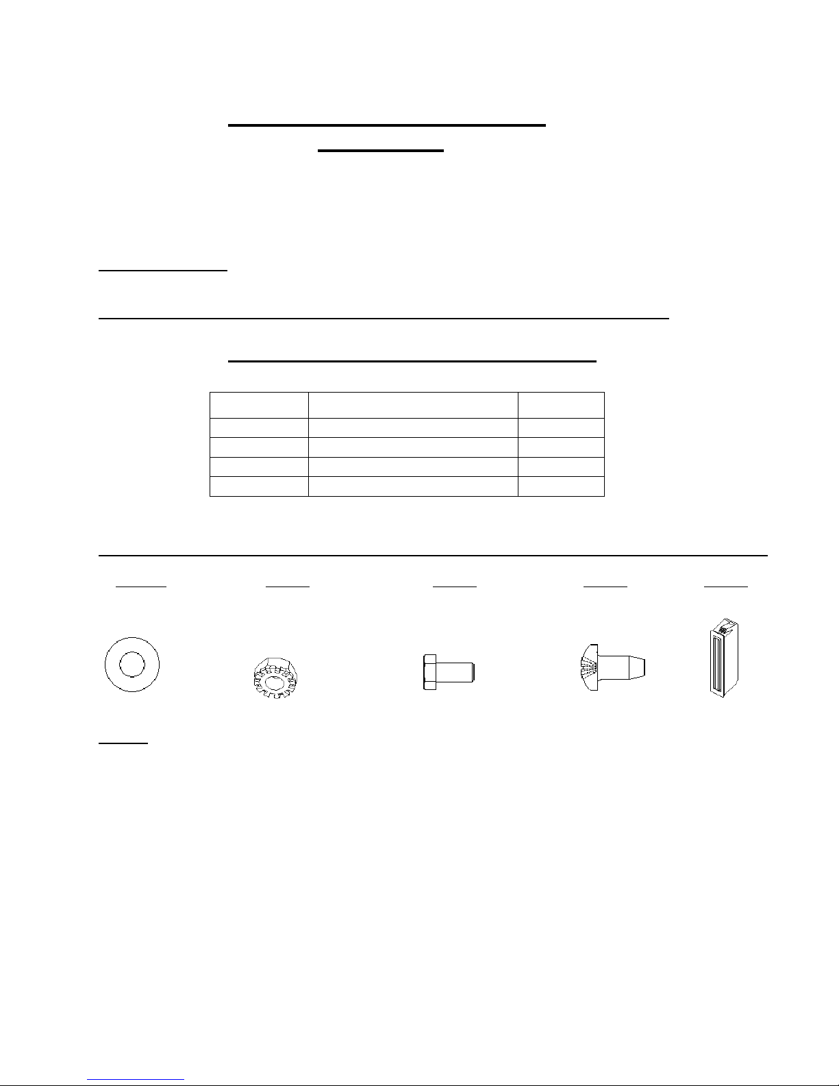
LIFT CABINET ASSEMBLY
SECTION #3
FOR STEP 1, HARDWARE NEED ONLY BE FINGERTIGHTENED
TOOLS REQUIRED: PHILLIPS HEAD SCREWDRIVER, ADJ WRENCH
*REMOVE ALL ITEMS FROM CARTON AND CHECK AGAINST THE FOLLOWING LIST:
*PARTS LIST – LIFT CABINET*
ITEM DESCRIPTION REQ’D
1 BOTTOM ANGLE LATCH 1
2 LIFT SIDE PAN W/HOLES 1
3 LIFT SIDE PAN NO HOLES 1
4 LIFT CABINET FACE 1
*REMOVE ALL ITEMS FROM THE HARDWARE PACK AND CHECK AGAINST THE FOLLOWING LIST:
ITEM 5 ITEM 6 ITEM 7
¼ FLAT WASHER ¼-20 KEPS NUT ¼-20X5/8 GD5 HX HD SCREW 10-24 ROLOK SNAP IN MAGNET
(12) REQ’D (6) REQ’D (6) REQ’D (2) REQ’D (8) REQ’D
ITEM 8
ITEM 9
STEP 1: ATTACH LEGS TO TOP
Prior to Step 5 in the first section, attach (1) lift side panel w/holes (Item 2) to the leg on the side where the over hang is. The
edge of panel with rectangular holes goes to the front. Use (4) 1/4-20x5/8 hex head screws (Item 7), (4) ¼-20 keps nuts (Item
6) & (8) ¼ flat washers (Item 5) to attach the panel, DO NOT TIGHTEN. Set (1) lift side panel with no holes (Item 3) on the
top support at the edge of the bench top with rectangular holes towards the front. Use (2) 1/4-20x5/8 hex head screws (Item
7), (2) ¼-20 keps nuts (Item 6) & (4) ¼ flat washers (Item 5) to attach the panel, DO NOT TIGHTEN. Measure the distance
from back edge of the bench top to the back of leg. Use that dimension to set lift side panels flush with the legs on the back
side. Also, make sure outer panel with no holes is flush with the side edge of bench top. See (Figure 10). Once panels are
located flush with the legs tighten hardware.
12
Page 13
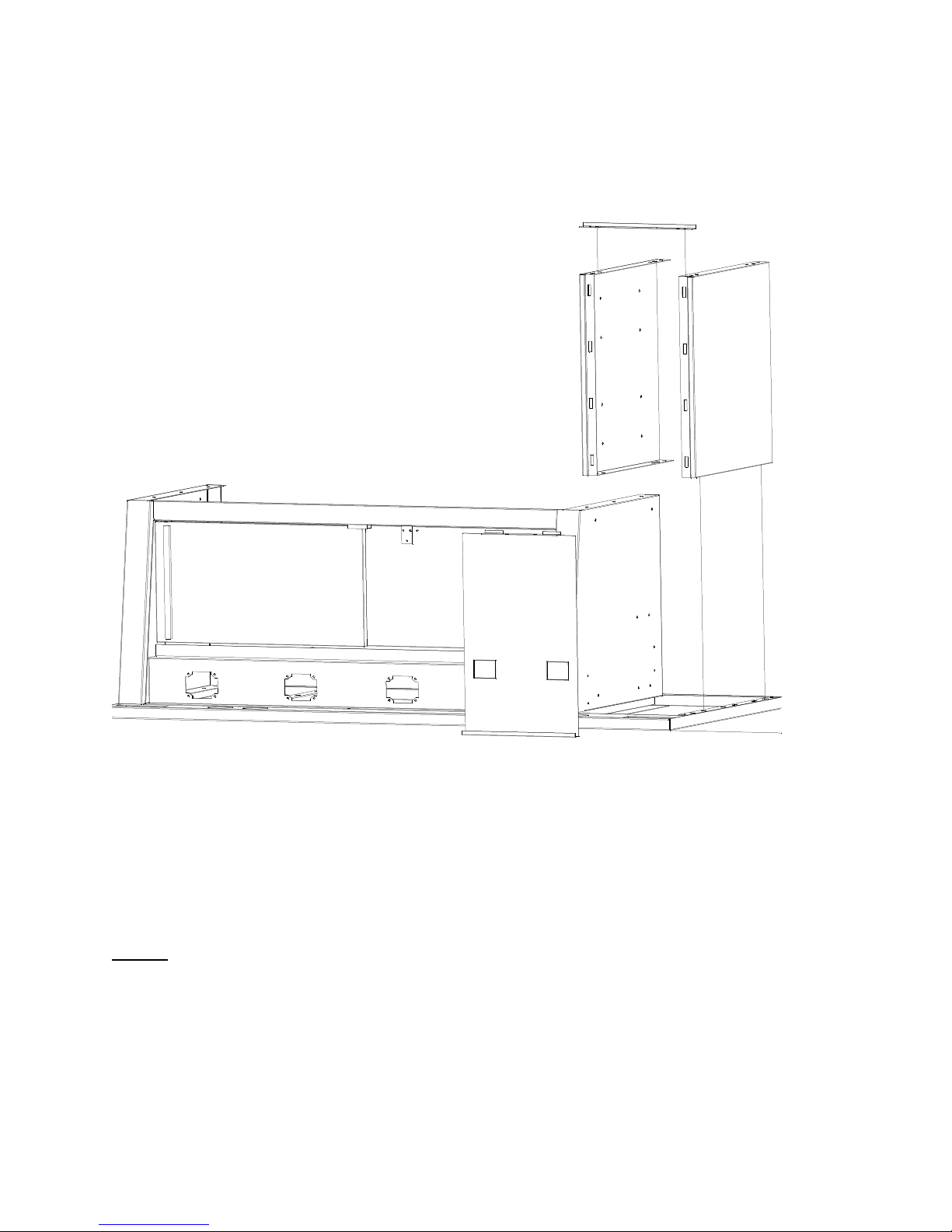
STEP 2: ASSEMBLE BOTTOM LATCH ANGLE
Once both side panels are tightened then attach (1) bottom angle latch (Item 1) to the underside of the side panels shown in
Figure 2. Use (2) 10-24 rolok screws (Item 8) to fasten bottom angle. If door fits too tight than loosen 10-24 rolok screws
and pull side panels apart to widen distance and then re-tighten.
Figure 10.
13
Page 14
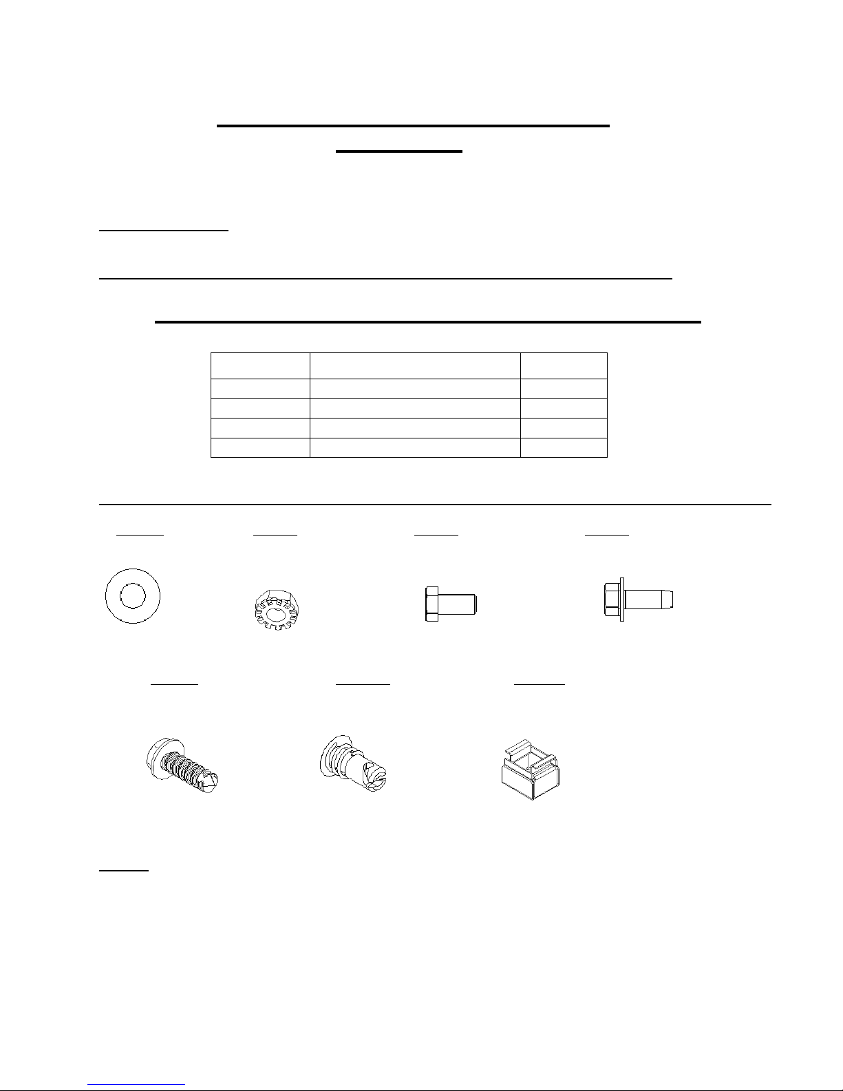
10 FEET PRO-SERIES ASSEMBLY
SECTION #4
FOR STEPS 1&2, HARDWARE NEED ONLY BE FINGERTIGHTENED
TOOLS REQUIRED: PHILLIPS HEAD SCREWDRIVER, ADJ WRENCH, FLAT HEAD SCREWDRIVER, CORDLESS
DRIVER WITH PHILLIPS ATTACHMENT, TAPE MEASURE
*REMOVE ALL ITEMS FROM CARTON AND CHECK AGAINST THE FOLLOWING LIST:
*PARTS LIST – 10FT W/CENTER SHELF UNIT*
ITEM DESCRIPTION REQ’D
1 CENTER DOOR 1
2 CENTER BASE SHELF 1
3 BACK STOP CHNL 1
4 24” FRONT FACE BRKT 1
*REMOVE ALL ITEMS FROM THE HARDWARE PACK AND CHECK AGAINST THE FOLLOWING LIST:
ITEM 5 ITEM 6 ITEM 7
¼ FLAT WASHER ¼-20 KEPS NUT ¼-20X5/8 GD5 HX HD SCREW ¼-20 x ¾ Hes Head SFS
(8) REQ’D (4) REQ’D (4) REQ’D (4) REQ’D
ITEM 8
ITEM 9 ITEM 10 ITEM 11
#14 x ¾ Hex Head SDS ¼ TURN SPRING LOADED ¼ TURN RETAINER
(1) REQ’D (2) R EQ’D (2) REQ’D
STEP 1: HANG BENCHES ON UNI-STRUT
Once both benches are hanging on the uni-strut slide the two together until the tops touch. NOTE: IF YOU DO NOT HAVE
A CENTER BASE SHELF THEN GO TO STEP 3. Bolt the center base shelf (Item 2) into position using (4) ¼-20 x 5/8 hx
hd screw (Item 7), (8) ¼ flat washer (Item 5), & (4) ¼-20 keps nuts (Item 6). DO NOT TIGHTEN.
14
Page 15
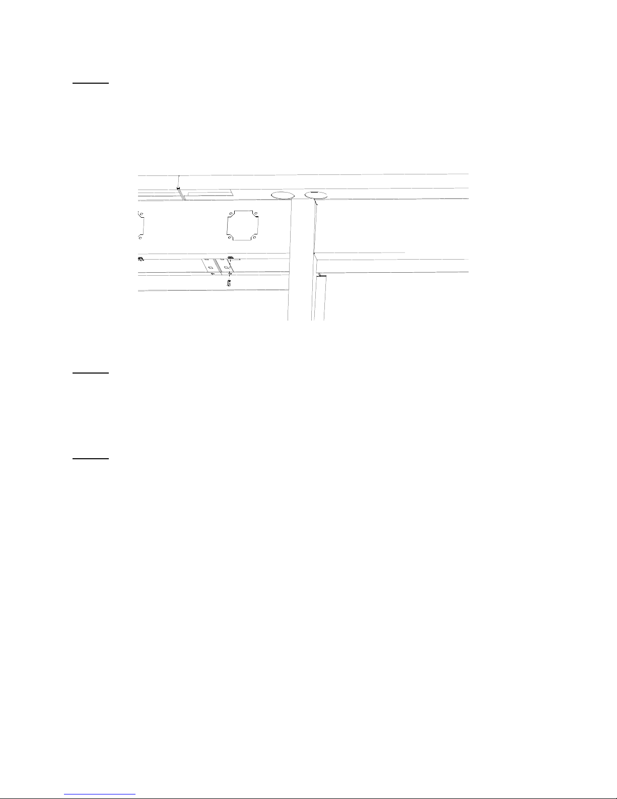
STEP 2: 24” FRONT FACE BRACKET
Insert the (2) ¼ turn retainers (Item 11) into the square holes in the 24” front face bracket. See (Figure 11). Next fasten 24”
front face brkt using (4) ¼-20 x ¾ hex head SFS (Item 8) into position, DO NOT TIGHTEN.
Figure 11.
STEP 3: TIGHTEN BENCHES
Tighten the (4) 3/8-16 x 1-1/4 hex head bolts that go to the uni-strut on both units. STOP HERE IF YOU DO NOT HAVE A
CENTER BASE SHELF. Then tighten the (4) ¼-20 x 5/8 hex head bolts (Item 7) that go to the center base shelf. Also
tighten the (4) ¼-20 x ¾ hex head SFS (Item 8) that hold the 24” front face. Lastly install (1) #14-3/4 Hex Head SDS (Item
9), in the front face going up through hole in front flange.
STEP 4: INSTALL CENTER DOOR
To install center door drop taps of door into slots in the shelf. Line up the holes in the door with the ¼ turn retainers (Item
11) and then install (2) ¼ turn spring loaded fasteners (Item 10) to hold door. See (Figure 12)
15
Page 16
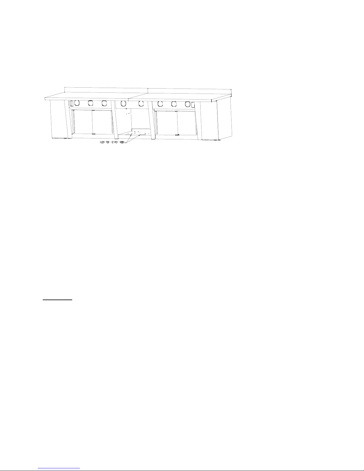
Figure 12.
GO TO SECTION #1, STEP #7
*NOTICE*
The following is the only warranty applicable to the products: the manufacturer warrants that the products are free from
defects in material or workmanship when installed, used and serviced in accordance with the manufacturer’s
recommendations. The manufacturer’s only obligation under this warranty shall be to replace any product, which is defective
in materials within one year or defective in workmanship within ninety days, from the date of installation. THE
FOREGOING WARRANTY IS EXPRESSLY IN LIEU OF ALL OTHER WARRANTIES, EXPRESS OR IMPLIED,
INCLUDING ANY WARRANTIES OF MERCHANTABILITY OR FITNESS FOR PURPOSE. The manufacturer shall not
be liable for any loss or damage, direct of indirect, resulting from the use or loss of use of the product. This warranty may
not be changed except by a written agreement signed by an officer of the manufacturer.
16
Page 17

17
 Loading...