

Page 1

Borofone Technology Co.,Ltd
Product recognition
product name wireless charger
Type products
BQ1
Products make up no
customer confirmation:
version
number
date
tabulati
on
investig
ate
ratify
V1.0
2018.8.6
Page 2

Borofone Technology Co.,Ltd
catalog
1 overview…………………………………………………………第 2 页
2 battery status………………………………………………………第 3 页
3 Productfunction and process description…………………………第 4 页
4 performance parameter……………………………………………第 5 页
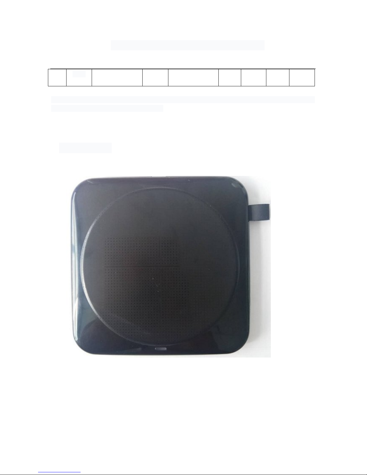
5 product appearance ………………………………………………第 6 页
1 overview
This specification describes the range of wireless charging and
transmitting applications produced by shenzhen meishiqi technology co.,
LTD,technological standard,Electrical Characteristics,Main material, The
main ingredient in,dimensions,Testing standards and other related items。
This specification can be used as the quality inspection standard and basis
of this product。
2 product function
2.1 W23 The wireless charging source board provides power to the
built-in circuit through MICRO interface input。
2.2 Working through the built-in conversion circuit through the wireless transmitter coil output,It
Page 3

Borofone Technology Co.,Ltd
can provide power for QI wireless charging mobile phones and other devices that support QI
wireless charging.
2.3 operating mode: When the launch pad is output normally, the green indicator is long and
bright。
2.4 standby mode: When the launcher is in standby mode without load, red indicates long
brightness。
2.5 Exception Modes: The launch pad is working abnormally,If metal is placed on the transmitting
coil or an incompatible receiving object,The red indicator is flashing continuously。
2.6 instructions
Plug the power cord into the MICRO input terminal on the wireless transmitter board,Stack the
receiver of a mobile phone that supports wireless charging in the position of the transmitter coil,The
indicator light on the transmitting panel shows that the green light is on for a long time, which is the
normal charging state。
(Adjust the best position to charge more quickly)
2.7 defensive function
Red indicator light flashes when metal objects are placed or incompatible receiving objects on
the transmitting coil.At the same time, the output conversion is stopped, and the normal standby state
is restored after the foreign body is removed,Normal output works when the correct receiver is
placed.
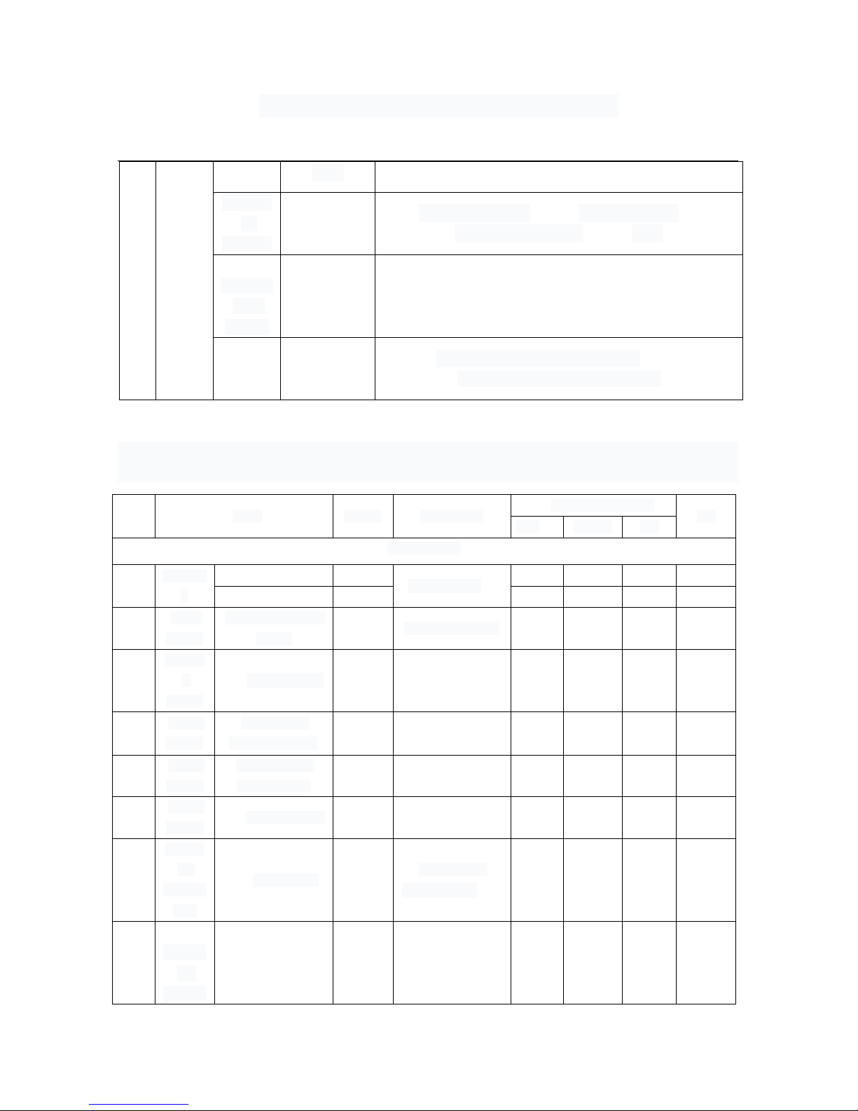
3 Product appearance and technology
NO
item test method Inspection standard/process
3.
1
product
appearance
visual
The appearance of the product shall meet the following
requirements:Reasonable wiring,Element arrangement,
No oxidation of welding disc and welding point,
achromatism,Overall appearance clean without stain,
Does not affect its commercial value
3.
2
product
proces
s
welding
require
ments
Eyeball, or
use a
magnifying
The soldering point is smooth and full,weld firmly,There
is no false welding,No virtual welding。
Page 4
Borofone Technology Co.,Ltd
glass
Enclosu
re
Material
√ Glass fiber double □ Glass fiber layer □
Ordinary single-layer □ other
PCB
technolo
gical
coating
√ Solder Coating
welding
technol
ogy
√Environmental protection welding □ NO
Environmental protection welding
4 Product electrical performance parameters
NO.
item symbol test method
inspection standard
unit
Max median min
Parameter
4.1
Efficienc
y
0.5A out η
input voltage 5V
72 %
1A out η 70 %
4.2
Static
current
No load consumes
current
IPWN The system is idle
55 mA
4.3
incomin
g
current
USB charge current IIN 1500 1200 mA
4.4
output
current
The receiver
outputs a current
I
OUT2
1050 1000 mA
4.5
output
voltage
Receiving end
output voltage
V
OUT
5.10 4.95 4.85 V
4.6
output
voltage
floating voltage V
OUT
5.20 5.10 4.95 V
4.7
Operati
ng
tempera
ture
output rating ℃
environment
temperature 25℃
65 50 ℃
4.8
NTC
protect
ed
thermo
ambient
temperature 25℃
℃ 70 65 ℃
Page 5
Borofone Technology Co.,Ltd
mete
After temperature detection and protection, the red light flickers continuously and returns to normal
operation after the temperature decreases.
5 product appearance:
Page 6

FCC Caution:
This device complies with part 15 of the FCC Rules. Operation is subject to the
following two conditions: (1) This device may not cause harmful interference, and (2)
this device must accept any interference received, including interference that may
cause undesired operation.
Any Changes or modifications not expressly approved by the party responsible for
compliance could void the user's authority to operate the equipment.
Note: This equipment has been tested and found to comply with the limits for a Class
B digital device, pursuant to part 15 of the FCC Rules. These limits are designed to
provide reasonable protection against harmful interference in a residential installation.
This equipment generates uses and can radiate radio frequency energy and, if not
installed and used in accordance with the instructions, may cause harmful interference
to radio communications. However, there is no guarantee that interference will not
occur in a particular installation. If this equipment does cause harmful interference to
radio or television reception, which can be determined by turning the equipment off
and on, the user is encouraged to try to correct the interference by one or more of the
following measures:
-Reorient or relocate th
e receiving antenna.
-Increase the separation between the equipment and receiver.
-Connect the equipment into an outlet on a circuit different from that to which the
receiver is connected.
-Consult the dealer or an experienced radio/TV technician for help.
To maintain complian
ce with FCC’s RF Exposure guidelines, This equipment
should be installed and operated with minimum 20cm distance between the radiator
your body: Use only the supplied antenna.
 Loading...