

Page 1

u1 40L - Install & Operation Manual
GB
Dispense options
Telephone
+44 (0)1362 695 006
Email
sales@borgandoverstrom.com
borgandoverstrom.com
Synergy House
Fakenham Road
Morton On The Hill
NR9 5SP
Chilled
Ambient
Chilled, Ambient & Sparkling
Contents
2 Model Overview
3 Component/Feature Overview
5 Installation
15 Operation
18 Maintenance & Cleaning
21 Advanced Troubleshooting
23 Exploded Diagrams & Parts List
26 Technical Information
29 Declarations of Conformity
Page 2
Install & Operation Manual
Borg & Overström GB2
Model Overview
COOLING SYSTEM Stainless steel direct chill coil
encased in a solid-block system
for instant response cool down
action. Ultra efciency compression
system with capillary control.
Environmentally friendly R134a
refrigerant.
COLD TEMPERATURE 2°C - 10°C.
OUTPUT PER HOUR
40 litres cold and sparkling at
<10°C.
DISPENSE Swan Neck Faucet with
ergonomically designed and situated
light touch sensitive controls.
MAX RUNNING POWER
CONSUMPTION
570 watt (during recovery), Rated
input 277 watt.
POWER SUPPLY 230V AC (50 Hz)
WATER CONNECTION Mains in - 1/4” Push Fit/ Faucet -
1/4” Push Fit
CO2 CONNECTION 1/4” Push Fit
DIMENSIONS (w x d x h) 330 x 370 x 362mm
WEIGHT 26Kg
CUPBOARD VENTILATION
Required
The u1 epitomises cutting-edge design
and innovation with its contoured tap
and compact under-counter unit. This is
our most discreet range and will t into
any environment seamlessly.
The under-counter dispenser is a dry
block cooler carbonator designed
to provide ambient still, chilled and
carbonated water. All the materials and
components are tested during the entire
production process in order to satisfy all
expectations.
Introduction
Page 3
Install & Operation ManualBorg & Overström GB
3
Component/Feature Overview
Contents:
1 no Electronic Swan Neck Tap
1 no 2/3-Button Membrane Control Panel
1 no 1.0m x 6mm Insulated Water Pipe
1 no Connector Box
1 no 4mm Self Adhesive Clip
1 no Fixings Set
Please Note:
Mains Installation Kit & Filters are supplied as extra items according to individual ordering requirement.
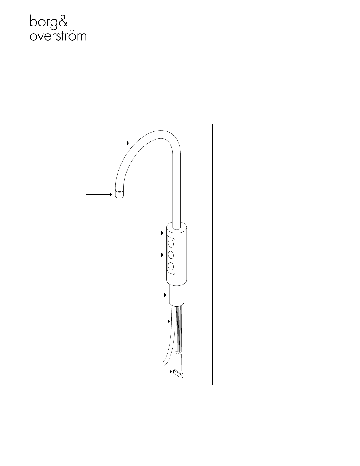
U1 Tap - Major Components
Swan Neck
Threaded Stem & Back Nut
Water Pipe
Electrical Connection
Main Body
Faucet
Membrane Control Panel
Page 4

Borg & Overström GB
4
Install & Operation Manual
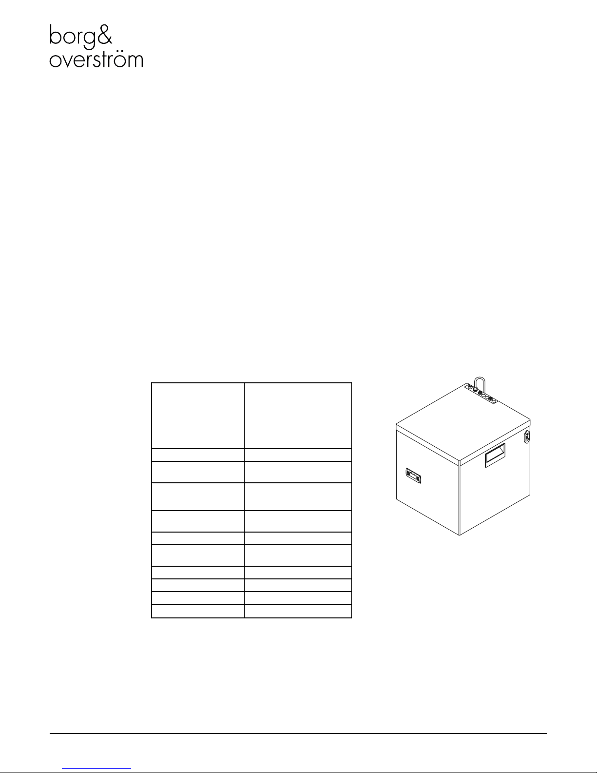
Major Components
Contents:
1 no Undercounter Unit
1 no 2.0m Power Cord Set
1 no 1.0m Faucet Connection Harness
1 no Co2 Regulator with Gauge & Connection
tube (Sparkling option only)
1 no Stainless Steel Drip Tray (c/w with Drain
Outlet Cap)
1 no Ventilation Ducting Kit
1 no Ventilation Grille
Faucet Connection Harness
CO2 Inlet
Water Inlet
Top Panel
Power Connection
Unit Carry Handle
Side Panel
Front Panel
Water Outlet
Eliwell Control Panel
Page 5

Install & Operation ManualBorg & Overström GB
5
Installation
Tap Installation
1
Identify a suitable location for the undercounter unit. It should
be positioned within 1.0m of the faucet, and within 2.0m of
suitable services connections. Allow enough space to t the
ventilation ducting system.
Service Requirements
Water: Mains potable water – internally regulated to 1.3bar. Min
mains pressure 1.3bar.
Electricity: 13A supply – Earth Leakage Protected.
2
33 - 35mm
3
187mm
4
When planning and providing
for the connection to the
services, always allow for
easily accessible service isolator
ttings and for the position of an
external water lter.
Identify a suitable position for the
swan neck faucet. A 33-35mm
(max) hole is required.
When positioning to drain over
an existing sink bowl, allow for
the reach of the swan neck or
otherwise the position of any
optional drip tray.
Page 6

Borg & Overström GB
6
Install & Operation Manual
400mm
Also allow for the height of
the swan neck under any
overhanging cupboard/shelf.
Carefully form the needed hole,
using the correct type of cutter
for the work surface material.
Observe all local occupational
health and safety requirements.
Remove the back nut and washer
from the faucet and carefully
feed the connecting pipe tail
and ribbon cable through the
hole formed in the work surface.
Ensure the sealing O ring is pre-
tted in the base of the faucet.
You may want to apply a thin
bead of silicone sealant also.
With the faucet control panel in
the right position, carefully ret
the back washer and nut. Take
care not to over-tighten.
5
9
8
Allow for the space needed
for forming the required hole.
Relate the selected position to
the underneath of the counter
and check for any obstructions.
Allow sufcient space for tting
the back nut to the faucet stem.
6
7
10
78mm
70mm
Install the ventilation system
using the instructions/templates
provided.
11 12
Fit optional Drip Tray at this
stage (if selected).
Once the ventilation system is
installed, position the unit on the
ducting as instructed and follow
the connection steps on page 9.
13
Page 7
Borg & Overström GB
7
Install & Operation Manual
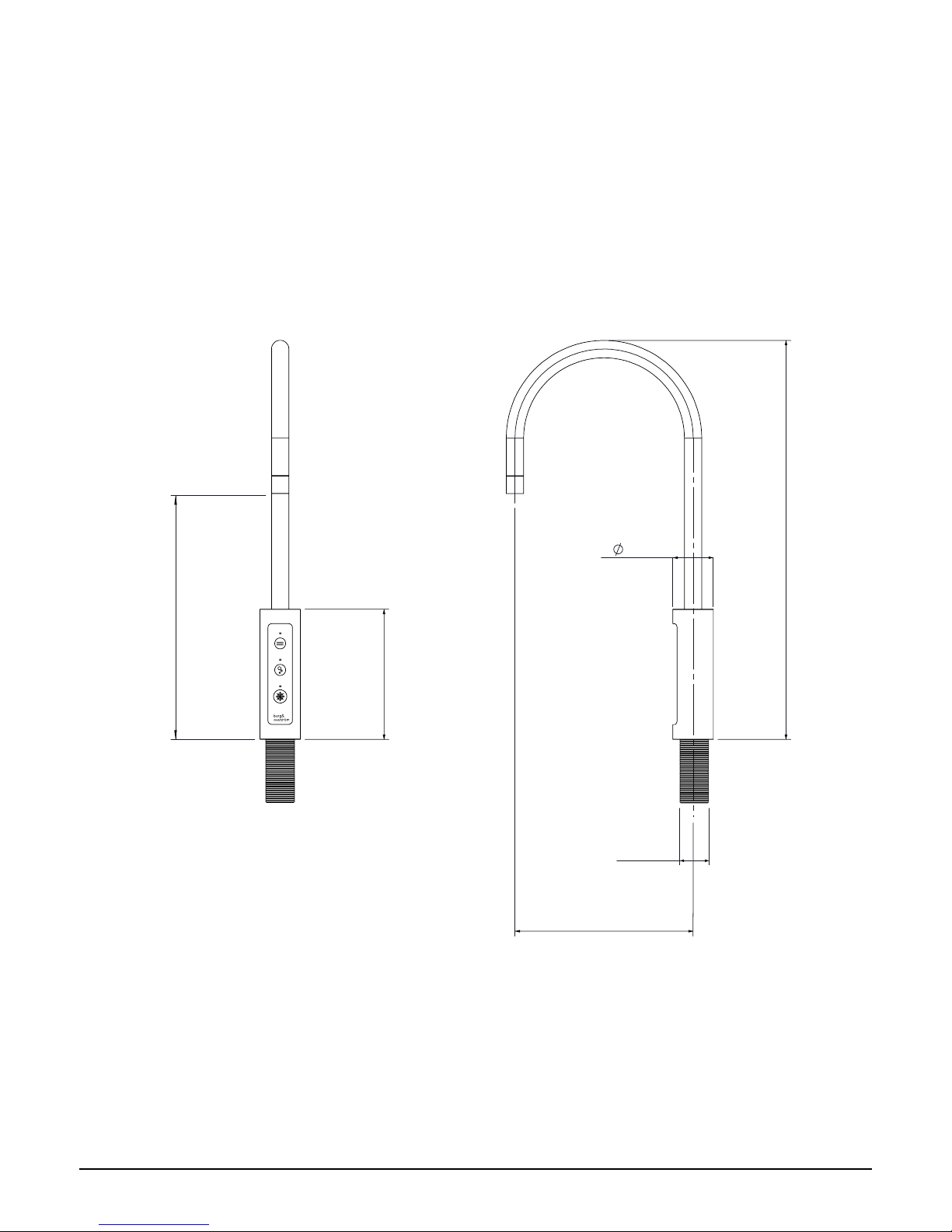
Tap Dimensions
135mm
414mm
188mm
42mm
260mm
33.3mm
Page 8
Borg & Overström GB
8
Install & Operation Manual
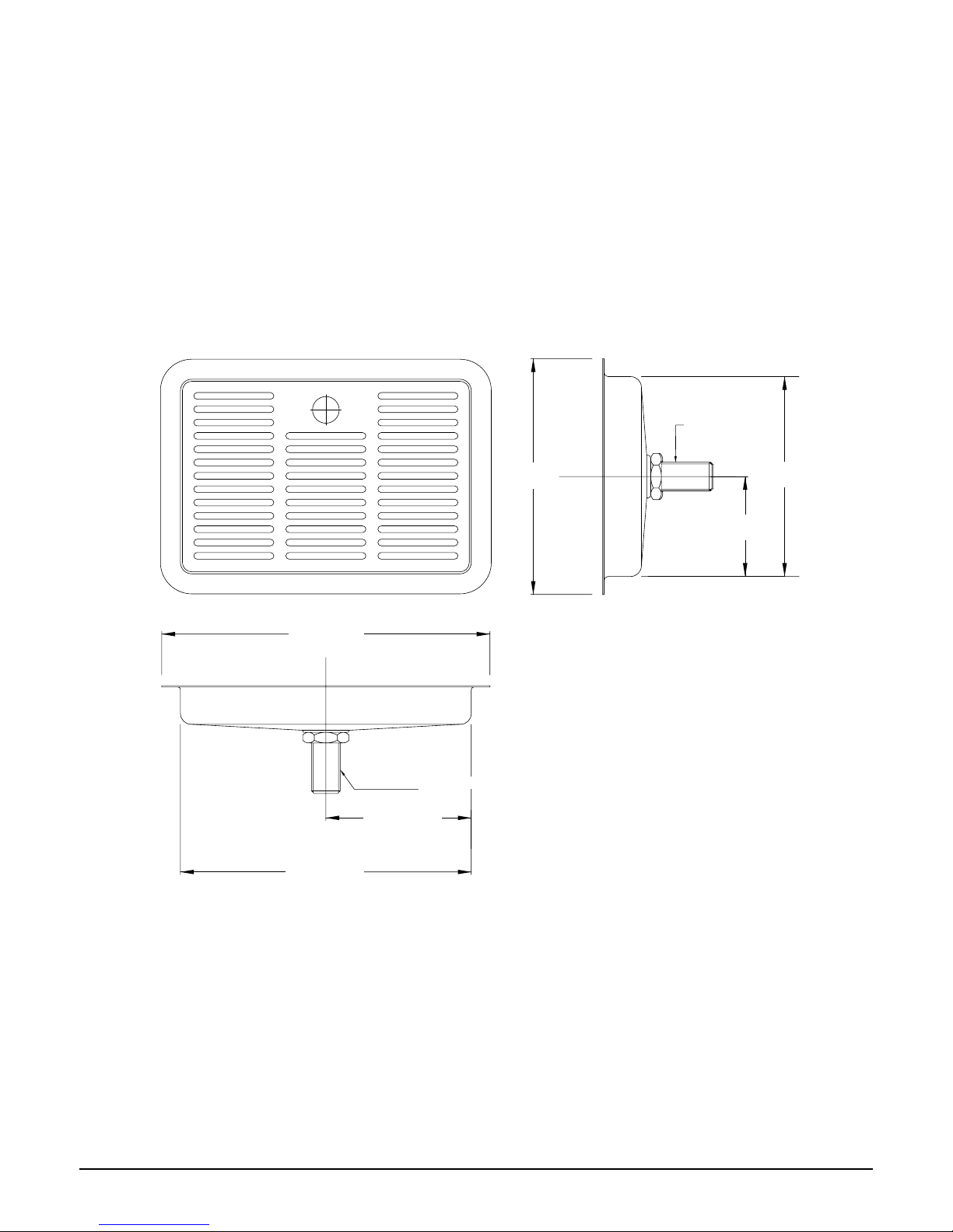
Driptray Dimensions
250mm/ 9¹³/16”
12.7mm/ ½” Waste Spigot
110mm/ 4 ¹¹/32”
220mm/ 8 ²¹/32”
12.7mm/ ½”
Waste Spigot
180mm/
7 ³/32”
150mm
/
5 ²9/32”
75mm/
2 ¹5/16”
Page 9

Borg & Overström GB
9
Install & Operation Manual
Ventilation System Installation
When Borg & Overström u1 undercounter
units are installed inside a cabinet or
housing, adequate ventilation is
recommended to ensure that they operate
satisfactorily.
During a cooling cycle it is normal for the
unit to produce heat, and the purpose of
ventilation is to provide a supply of air
that can absorb the generated heat which
would otherwise accumulate inside the
cabinet or housing, and reduce the cooling
performance of the unit. The amount of heat
generated by the cooling cycle depends
directly upon the amount of usage – the
higher the usage, the more heat produced.
To provide adequate ventilation we
recommend that air grilles/vents are tted
as supplied (or vent apertures formed) in
the cabinet to allow an airow as shown
below. Normally this should be enough for
all situations.
In conjunction with an inlet vent grille set into
the front of the plinth, it is recommended that
a ducting box and duct is installed in the
base of the cabinet. Another slot located in
the base is responsible for allowing airow
past the condenser positioned at the rear of
the dispenser. Instructions for installing the
ventilation system are as follows:
Using the supplied templates, cut the bottom and kickboard panel of the installation cabinet.
Kickboard Cutout
Bottom Cutout
(To align with vent
in bottom of unit)
Kickboard Panel
1
Bottom Panel
Rear Bottom Cutout (To
align with ducting at rear
of unit)
Page 10

Borg & Overström GB
10
Install & Operation Manual
Insert ducting box into its cut slot in the Bottom panel. Then insert the air ducting into the ducting box until it reaches its limits.
Then cut the air ducting so that it is ush with the kickboard.
Centrally locate the ventilation grille over the kick board cut out, then using self tapping screws, secure the kick plate.
The unit must be positioned accurately over the air ducts to ensure optimum airow.
Ducting Box
Air Ducting
Air Flow
Air Flow
2
3
4
Align duct with
rear cut out
Rear Cut
Out
Page 11

Borg & Overström GB
11
Install & Operation Manual
Undercounter Installation & Water Connection
1
2
7
8
9
10
11
Locate the machine in a
suitable enclosure, ensuring
that the supplied ventilation kit
can be installed.
Connect the u1 tap to the
water outlet.
Connect the faucet connection
harness to the tap control
panel membrane.
Connect the CO2 supply
from gas regulator, ensuring
the pressure is set to max 58
PSI (4 bar), and turn on the
supply.
Connect the chiller to the
water supply and open the
mains supply isolation valve.
Connect the unit to the
electrical supply and turn on.
After approximately 10
minutes, the compressor and
fan will stop as the chiller has
reached its normal operating
temperature.
The carbonator should be
purged of air by activating the
sparkling water dispense for
approximately 20 seconds.
Isolate the water supply
and activate the sparkling
water dispense. When the
water system has emptied,
allow gas to be expelled for
approximately 5 seconds.
Immediately after this 5
second period restore the
water supply and allow the
system to rell.
Dispense ambient, still and
sparkling water, in turn,
to purge any air from the
system. The time to do this
may vary depending on the
length of pipe between the
unit and the tap.
3
6
5
10
mins
58 PSI
20
secs
Install within connection box
as supplied.
4
Page 12

Borg & Overström GB
12
Install & Operation Manual
The unit should be isolated from the electricity supply before removal of any covers.
Great care must be employed when working with high pressure carbon dioxide, and
in no cases should the maximum operating pressure of 58 PSI (4 bar) be exceeded.
Safety
Faucet Connection
Harness
Water Pipe
Tap
Co2 Pipe
Co2 Bottle
Tap Control Panel
Membrane
Page 13

Borg & Overström GB
13
Install & Operation Manual
1
Remove the 3 screws holding
the unit lid down and lift the
lid away
Locate the ow control adjuster,
this can be found on top of the
carbonator can, connected to
the central port of the can.
Loosen the lock nut, but do
not remove.
Flow can then be adjusted
by turning the adjuster screw,
anti-clockwise to increase ow
and clockwise to restrict ow.
After each adjustment the ow
rate should be timed.
Sparkling Water Flow Rate
NOTE: The soda water ow rate is set to 35ml/sec at a CO2 pressure of 58 PSI (4 bar). To
adjust the soda water ow rate follow these steps:
Once the correct ow rate is achieved reverse steps 1, 2 and 3.
1
2
3 4
Page 14
Borg & Overström GB
14
Install & Operation Manual
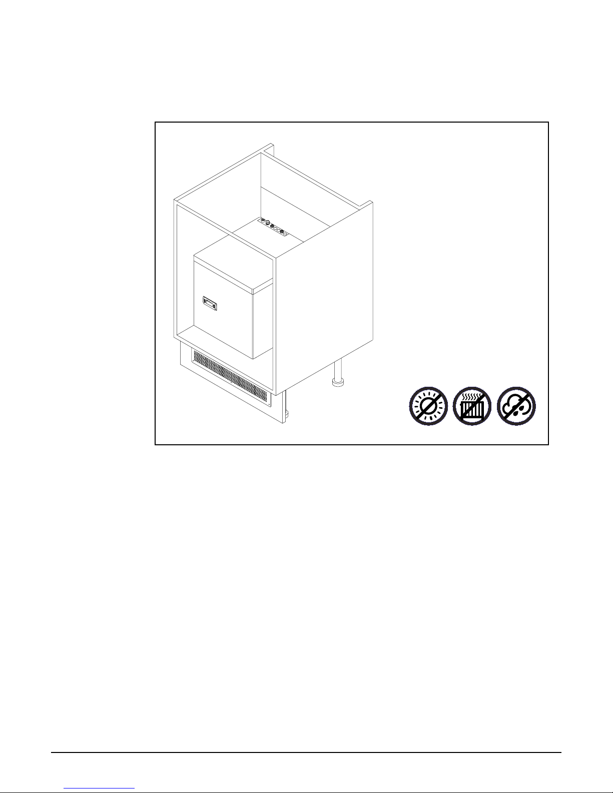
General Safety
• Always place the dispenser in its
vertical position, on a surface which
can capably support its weight.
• During use this machine must remain
in its upright position.
• Adequate ventilation must be
allowed for - we recommend using
the supplied ventilation ducting kit.
• Keep the machine away from
sunlight, heat and moisture.
• Power and water supply points must
be available near the dispenser,
and must meet the criteria specied
in the ‘Specication’ section of this
manual.
• The environment where this machine
is installed must be free of dust and
corrosive/explosive gases.
Page 15
Install & Operation ManualBorg & Overström GB
15
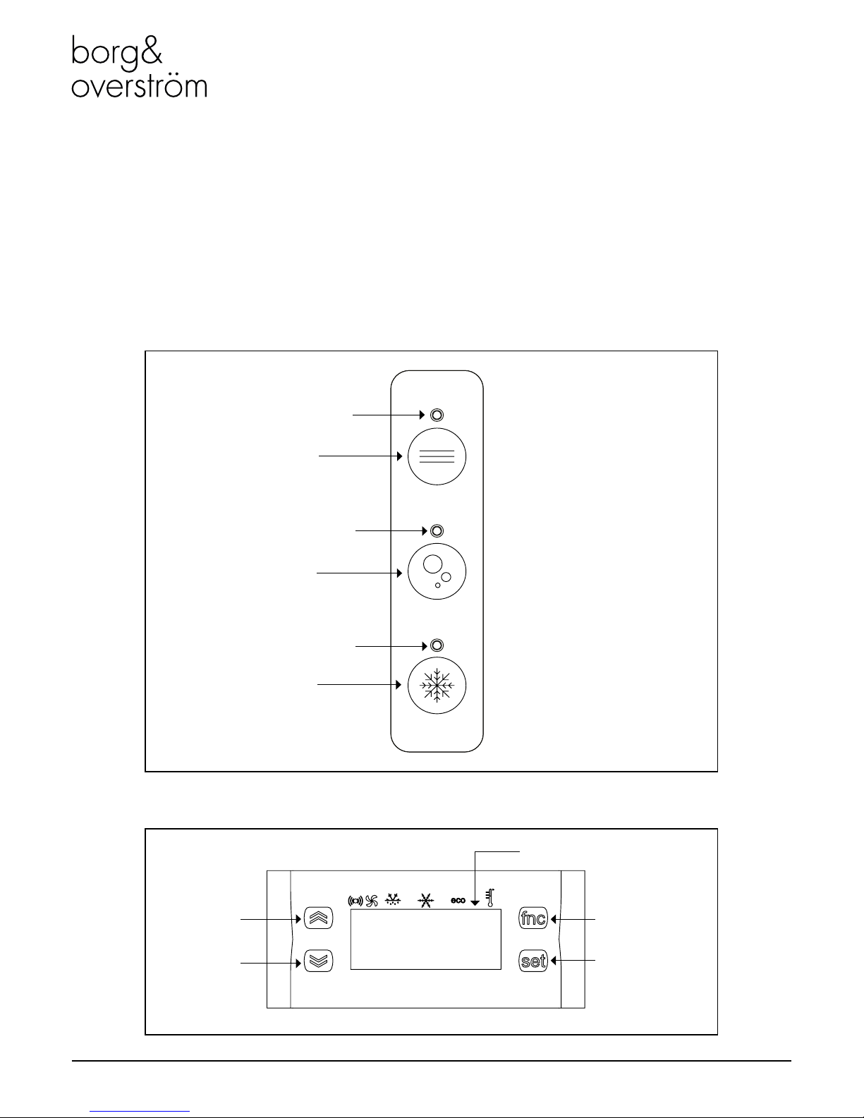
Operation
Ambient Water Button
Cold Water Button
Ambient Water Indicator
Functions & Controls
Sparkling Water Button
Sparkling Water Indicator
Cold Water Indicator
Tap Control Panel
8888
Control Button
Eliwell Control Panel
Control Button
Function Button
Setting Button
Digital Display
Page 16

Borg & Overström GB
16
Install & Operation Manual
1. Switch on Mains power – the display will
ash several times, then the fridge system
will switch on and the display will give a
steady reading, this is the temperature of
the water bath sensor.
2. Press and release the ‘Set’ button – The
display will show ‘SET’.
3. Press ‘Set’ again and the display will show
a numeric value (e.g. 9°C).
4. Raise or lower this gure to the desired
setting using the up or down arrows on the
left of the control display window.
5. When the correct setting is shown in the
display window press ‘Set’ button the
display will now show SET.
6. Press FNC button to return to the probe
temperature reading.
Basic Settings
Adjusting the Set Point:
1. Press and hold the ‘Set’ button until CP
shows on the display – Release the button.
2. Press ‘Set again, DIF will show on the
display.
3. Press ‘Set’ again and the display will show
a numeric value, (e.g. 1°C, the default
setting.)
4. Raise or lower this gure to the desired
setting using the up or down arrows on the
left of the control display window.
5. When the adjustment has been made press
‘Set’ again the display will show DIF.
6. If no further changes are required press
FNC again to exit.
Altering the Differential setting:
NOTE: If no buttons are pressed for 15 seconds, the control will revert to temperature display
mode,and any changes to settings will be saved.
Controls
Power Connection Socket
Note: the undercounter unit
automatically powers up when the
power lead is connected.
Page 17
Borg & Overström GB
17
Install & Operation Manual
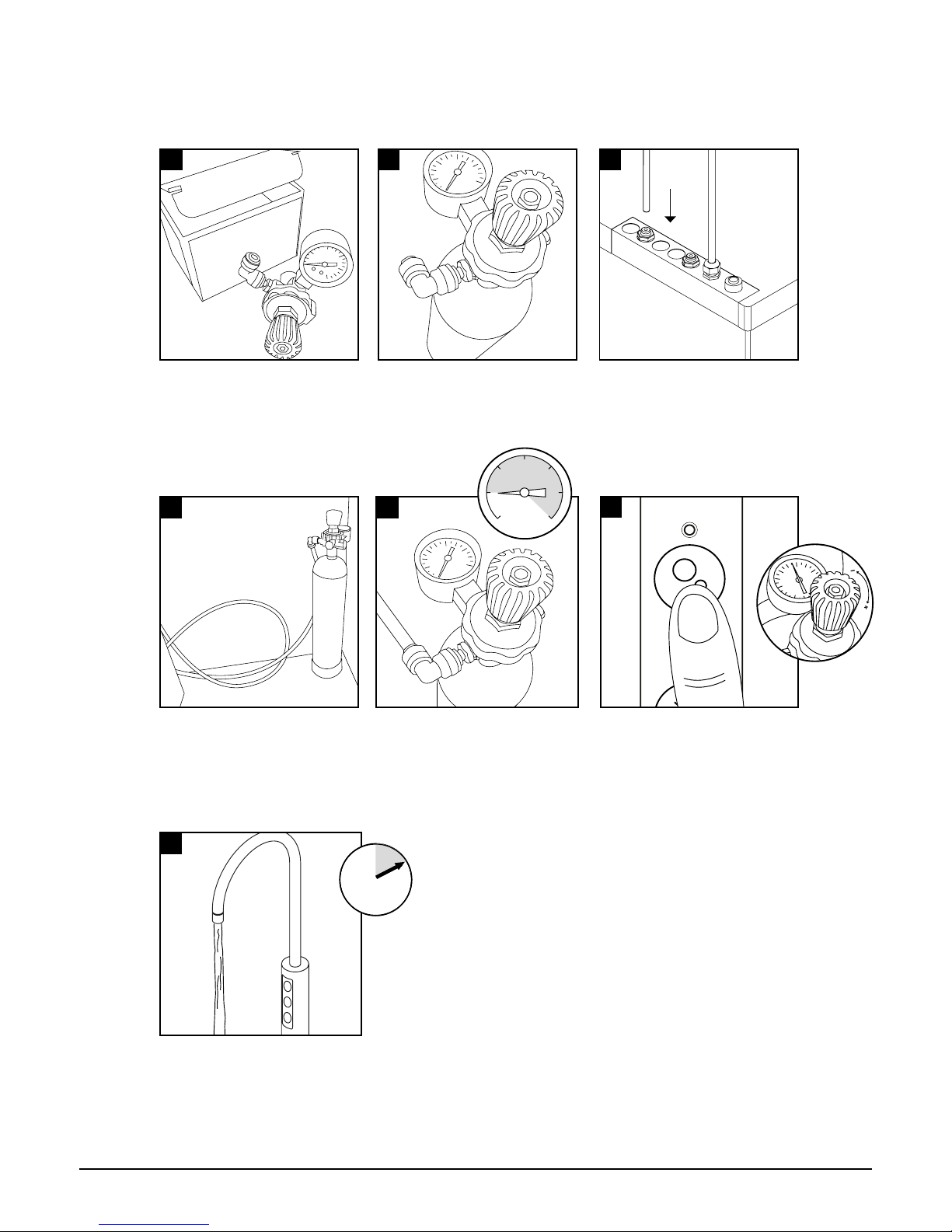
CO2 Bottle Installation
Allow the machine to stand for 8 - 12
minutes for the initial chilling process to
complete.
Unpack CO2 Regulator and t elbow tting
to spigot outlet.
Attach the regulator to the disposable CO2
bottle, ensuring the small pressure relief
vent in the stem is facing away from you or
anyone else. Ensure the regulator is closed.
Hand tighten securely.
Stand the cylinder in a suitable place.
It is necessary to prime the sparkling system
with CO2 - push the sparkling button for a
few seconds until CO2 is coming through.
Check and adjust the CO2 pressure
accordingly.
Connect the assembled CO2 bottle and
regulator to the CO2 inlet using a ¼” pipe.
We recommend between 3.5 - 4 bar(58
PSI) (max). Do not exceed 4 bar pressure.
58 PSI
2
4
5
6
7
1 3
10
mins
Page 18

Install & Operation ManualBorg & Overström GB
18
Maintenance & Cleaning
Sanitisation Guide
NOTE: All maintenance operations must be carried out with the dispenser switched off. This
operation must only be carried out by trained staff. Every 6 months a sanitisation procedure is
recommended as follows:
Turn off incoming mains water.
Connect to lter head.Add 25 ml of Bioguard Internal
Sanitisation uid to a clean and
empty service lter cartridge.
Turn on incoming water, allow
service cartridge/doser to ll.
1
3
2
4 5
7
Dispense water using the cold
button until the water appears pink.
Briey press the ambient button
too. Repeat with sparkling button
if present.
Briey press cold/ambient dispense
button to release internal water
pressure from the machine.
Remove the existing lter.
Use Bioguard Hand Gel and put
on protective gloves.
8
Leave the solution inside machine
for sanitisation to take effect
(minimum 5 minutes) while
thoroughly cleaning the machine
externally
9
6
PINK
5
mins
Page 19

Borg & Overström GB
19
Install & Operation Manual
For this we recommend the use
of Bioguard Foam Descaler &
Sanitiser Spray.
Turn off water and remove the
service lter. Retain service lter
for reuse.
When the external cleaning
(minimum 5 minutes) is
completed, ush the machine
using the cold button with clean
water until the dispense water
runs clear. Repeat briey with the
ambient and sparkling buttons.
Fit new lter. Turn on incoming
water supply and reconnect the
power.
10
12
11
13
Pre-ush the new lter to waste
using the ambient button until
the water appears clear and is
free of air. Flush through a small
amount of water to check all
functions.
Pay particular attention to the
dispense faucet and the push
button controls. For this use
Bioguard External Sanitiser &
Clear Spray and Sanitising
Wipes.
Attend to any cosmetic marks
with Bioguard Rejuvenator &
Protector as needed.
Remember to include the drip
tray. If a Waste Overow
System is tted, empty this
and ush through with a small
amount of sanitisation uid if
needed.
15
14
16
17
Please note that this sanitisation uid contains an
active caustic/alkaline agent.
Always use responsibly and with care remembering
that due to its alkaline nature unnecessary
concentrated/prolonged contact with any materials,
including metals, can cause damage. Always rinse
all contact surfaces after use with clean water.
Avoid skin contact and wear
protective gloves when
handling sanitisation uids.
In the event of any skin
contact, ush immediately
with clean, cold water.
5
mins
PINK
5
mins
Page 20

Borg & Overström GB
20
Install & Operation Manual
Emptying the CO2 Tank
1
Turn off the water supply.
3
2
Press and hold the Sparkling
water dispense button until all
the water is expelled and only
CO2 gas is being released.
The tank is empty of sparking
water when only CO2 is being
released.
4
Ensure to release the Sparkling
water button and take care to
avoid releasing excess amounts
of CO2 gas as this may
damage the tank.
Page 21

Install & Operation ManualBorg & Overström GB
21
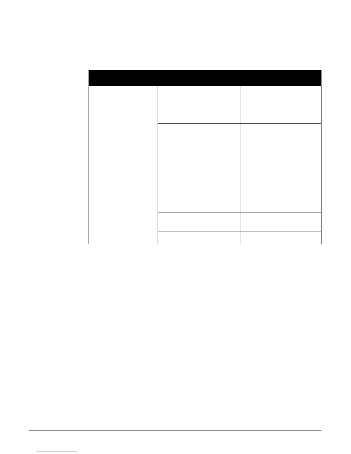
Problem/Report Possible Cause Suggested Action
No Water Dispensing Water Pressure Regulator Check water tank ow through the
regulator. Replace if necessary.
No Sparkling Water No CO2 pressure, check by operating
pressure relief valve on carbonator tank.
Check CO2 bottle, regulator and nonreturn valve. Supply pressure should be 58
psi (4bar), adjust or replace as necessary.
Carbonator Tank Not Filling Check carbonator probe for possible short
circuit to ground.
Check for pump timeout, cycle power off
& on then purge carbonator.
Check supply to water pump (230V AC),
if voltage present & pump inoperative replace pump.
If voltage not present & pump is not
timed out, check control board fuses. If
necessary replace control board.
Poor Quality Carbonation Incorrect CO2 Pressure Check CO2 bottle, regulator and non-
return valve. Supply pressure should be 58
psi (4bar), adjust or replace as necessary.
Air in Carbonator Tank Isolate the power supply and operate the
sparkling water tap until gas is expelled.
Allow gas to expel for 5 seconds. Switch
on power supply and allow the tank to
rell.
Residue in Carbonator Tank After prolonged use, a surface lm can
develop within the carbonator tank. Refer
to cleaning and sanitising instructions.
Carbonator Tank is Overlled If pump runs continuously, check
connections to tank level probe, if problem
persists replace the PCB.
Advanced Troubleshooting
Fault Diagnostics
Page 22
Borg & Overström GB
22
Install & Operation Manual
Fault Diagnostics (Continued)
Problem/Report Possible Cause Suggested Action
Warm Drinks Insufcient cooling air ow through the
fridge.
Check that the condenser is not blocked.
Check supply to cooling fans (230V AC).
If supply present replace fans.
If supply not present move on to the
compressor. The supply to the fans and the
compressor are linked.
Compressor not running Check supply to compressor (230V AC).
If supply not present check the Eliwell
fridge controller is operating.
Check for system over heat. Allow the unit
to cool and check for airow obstructions.
Once the unit has cooled the fridge system
will restart. If the problem persists contact
technical support.
If the Eliwell controller is operating check
the operating parameters are correctly set
and inspect the probes. Replace probes
as necessary.
Eliwell fridge controller not operating. Check supply to the controller. If present
replace the controller.
If supply is not present check the PCB.
PCB not operating. Check the fuses on the board and the fuse
in the mains plug. If fuses are ok replace
the PCB.
Fridge failure If compressor & fan are running and there
is no cooling contact technical support.
Page 23

Install & Operation ManualBorg & Overström GB
23
603002
Exploded Diagrams & Parts List
Tap Exploded Diagram
607131
604001
601254
601254
603001
603002
607132
Page 24

Borg & Overström GB
24
Install & Operation Manual
Chilled, Ambient & Sparkling Exploded Diagram
637325
637408
637426
637106
637107
637326
462374
637324
637425
462668
462313
635512
632031
462359
462874
462362
462371
172180
462667
632032
462376
462384
462368
462325
462318
462364
462369
637417
462013
462014
462012
Page 25

Borg & Overström GB
25
Install & Operation Manual
Borg & Overstrom
Part No
Description
601254 u1 Tap Assembly complete with O-ring, Nut and washer set
603001 u1 tap replacement O-ring
603002 u1 tap O-ring, Nut and washer set
604001 u1 Swan Neck Tap Aerator Set
607131 u1 Tap Chilled & Ambient Control Panel Membrane
607132 u1 tap Chilled, Ambient & Sparkling Control Panel Membrane
Tap Parts List
Parts List
Borg & Overstrom
Part No
Description
172180 Swan Neck Faucet Connection Harness
462012 3/8 LLDPE BU TUBE
462013 1/4 LLDPE BU TUBE
462014 5/16 LLDPE BU TUBE
462313 Straight Adaptor, 3/8x1/4 BSP
462318 Equal Tee, 1/4
462325 Bulkhead Connector, 1/4
462359 Equal Tee, 3/8
462362 Equal Elbow, 3/8
462364 Stem Adaptor, 3/8ODx1/4BSP
462368 Stem Elbow, 1/4-1/4
462369 Stem Elbow, 3/8-1/4
462371 Stem Elbow, 3/8-3/8
462374 Reducer, 3/8-5/16
462376 Equal Elbow, 5/16
462384 Stem Elbow, 5/16-5/16
462667 Single Check Valve, 5/16
462668 Single Check Valve, 1/4
462874 Reducing Straight Connector, 5/16-1/4
632031 DRY047 Front Wrap
632032 DRY045 Lid
633512 Can Wrap Insulation
637106 Solenoid Dispense Control Board
637107 EXL170 CLIP III Control Board
637324 3 Way Dispense Solenoid
637325 Flow Control
637326 Eliwell Control
637408 Axial Fan 240V
637417 12V Power Supply
637425 Aquatec Pump IPC1400 MOTOR ASSEMBLY
637426 Bit Regulator 1.3bar TYP 88259R6
Page 26

Install & Operation ManualBorg & Overström GB
26
COOLING SYSTEM Stainless steel direct chill coil encased in a solid-block
system for instant response cool down action. Ultra
efciency compression system with capillary control.
Environmentally friendly R134a refrigerant.
COLD TEMPERATURE 2°C - 10°C
OUTPUT PER HOUR 40 litres cold and sparkling at <10°C.
DISPENSE Swan Neck Faucet with ergonomically designed and
situated light touch sensitive controls.
MAX RUNNING POWER CONSUMPTION 570 watt (during recovery)
RATED INPUT 277 watt
QUANTITY OF REFRIGERATION GAS R134a 130g
POWER SUPPLY 230V AC (50 Hz)
WATER CONNECTION Mains in - 1/4” Push Fit/Faucet - 1/4” Push Fit.
CO2 CONNECTION 1/4” Push Fit.
DIMENSIONS (w x d x h) 330 x 370 x 362mm
WEIGHT 26Kg
RATED CURRENT 2A
FUSE RATING 5A
INLET WATER PRESSURE 22 PSI (1.5Bar) - Internally regulated to 22 PSI (1.5Bar).
CO2 PRESSURE 58 PSI (4 Bar) Maximum
COMPRESSOR Tecumseh THB4422Y
CLIMATIC CLASS N
Technical Information
Specication
Page 27
Borg & Overström GB
27
Install & Operation Manual
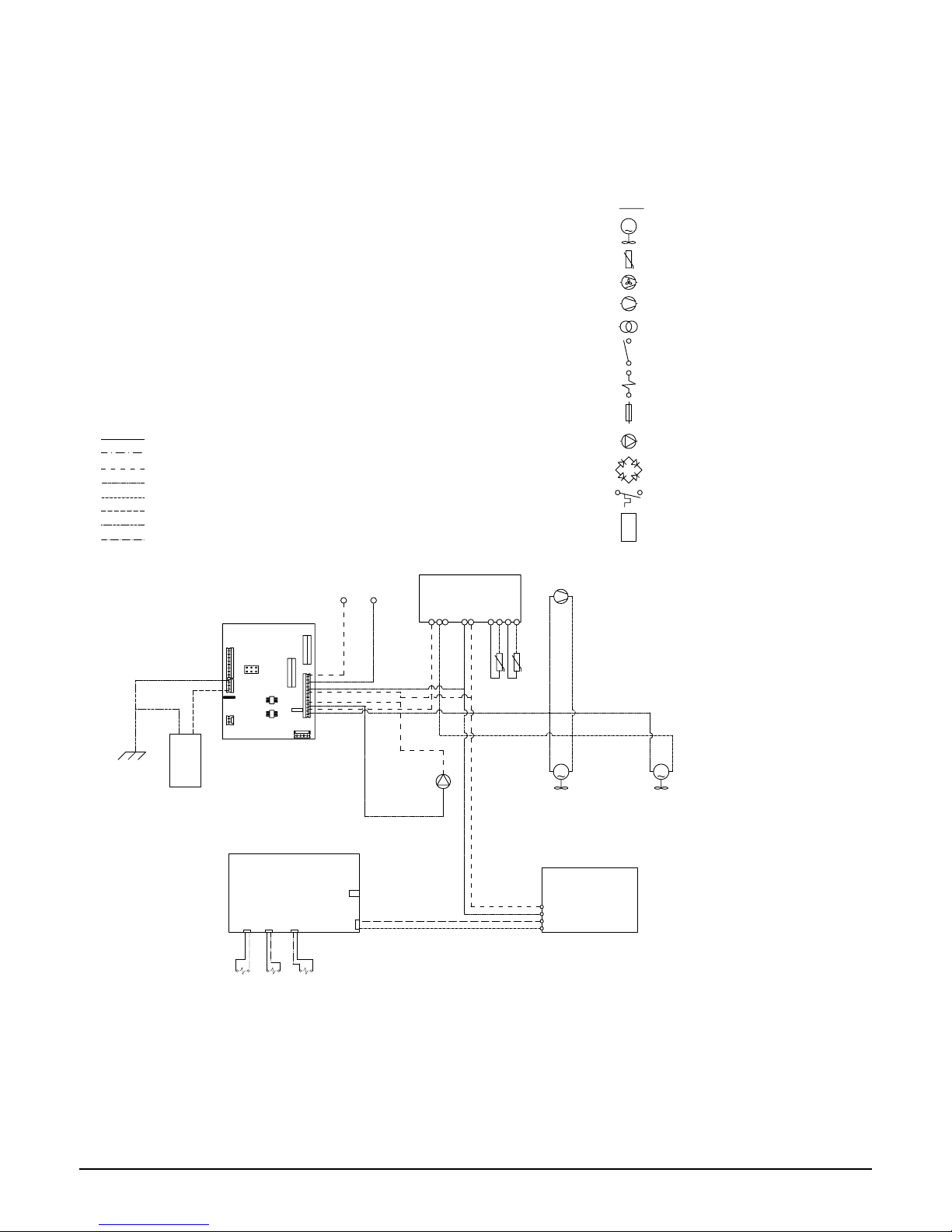
Circuit Diagram
1
2
3
4
5
6
7
8
9
10
11
12
13
4
3
2
1
9
8
7
6
5
4
3
2
1
5A
5A
230 AC
INLET
M
M
BROWN
BLUE
WHITE
YELLOW
GREEN
PURPLE
BLACK
RED
KEY
FAN
COMPRESSOR
TRANSFORMER
SWITCH
SOLENOID
FUSE
PUMP
BRIDGE DIODE
TEMPERATURE SWITC
H
CARBONATOR CAN
M
TEMPERATURE PROBE
CONDENSER FAN
12Vdc POWER SUPPLY
RIBBON CABLE
CONNECTION TO TAP
AMBIENT
DISPENSE
SOLENOID
CHILLED
DISPENSE
SOLENOID
SPARKLING
DISPENSE
SOLENOID
Page 28
Borg & Overström GB
28
Install & Operation Manual
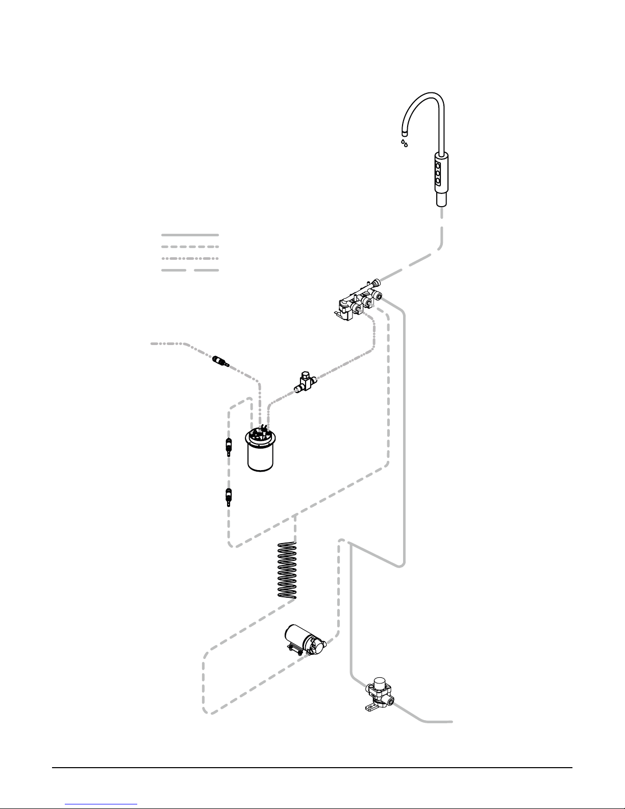
Water Pathway Diagram
CARBONATION
PUMP
CARBONATION TANK
TAP WATER OUT
AMBIENT
CHILLED
SPARKLING
MIXED LINE
WATER IN
WATER COIL
NON
RETURN
VALVE
NON
RETURN
VALVE
CARBONATION
FLOW CONTROL
WATER PRESSURE
REGULATOR
CO2 IN
NON
RETURN
VALVE
Page 29

Borg & Overström GB
29
Install & Operation Manual
Page 30

Borg & Overström GB
30
Install & Operation Manual
Page 31

Borg & Overström GB
31
Install & Operation Manual
Page 32

Borg & Overström GB
32
Install & Operation Manual
© Copyright Borg & Overström.
This manual is printed by Borg & Overström and shall not be reproduced or copied in anyway.
Document Reference: u1.40.I&OM.v28022018
 Loading...