

Page 1
PARTS LIST INSTALLATION AND GENERAL,
INFORMATION
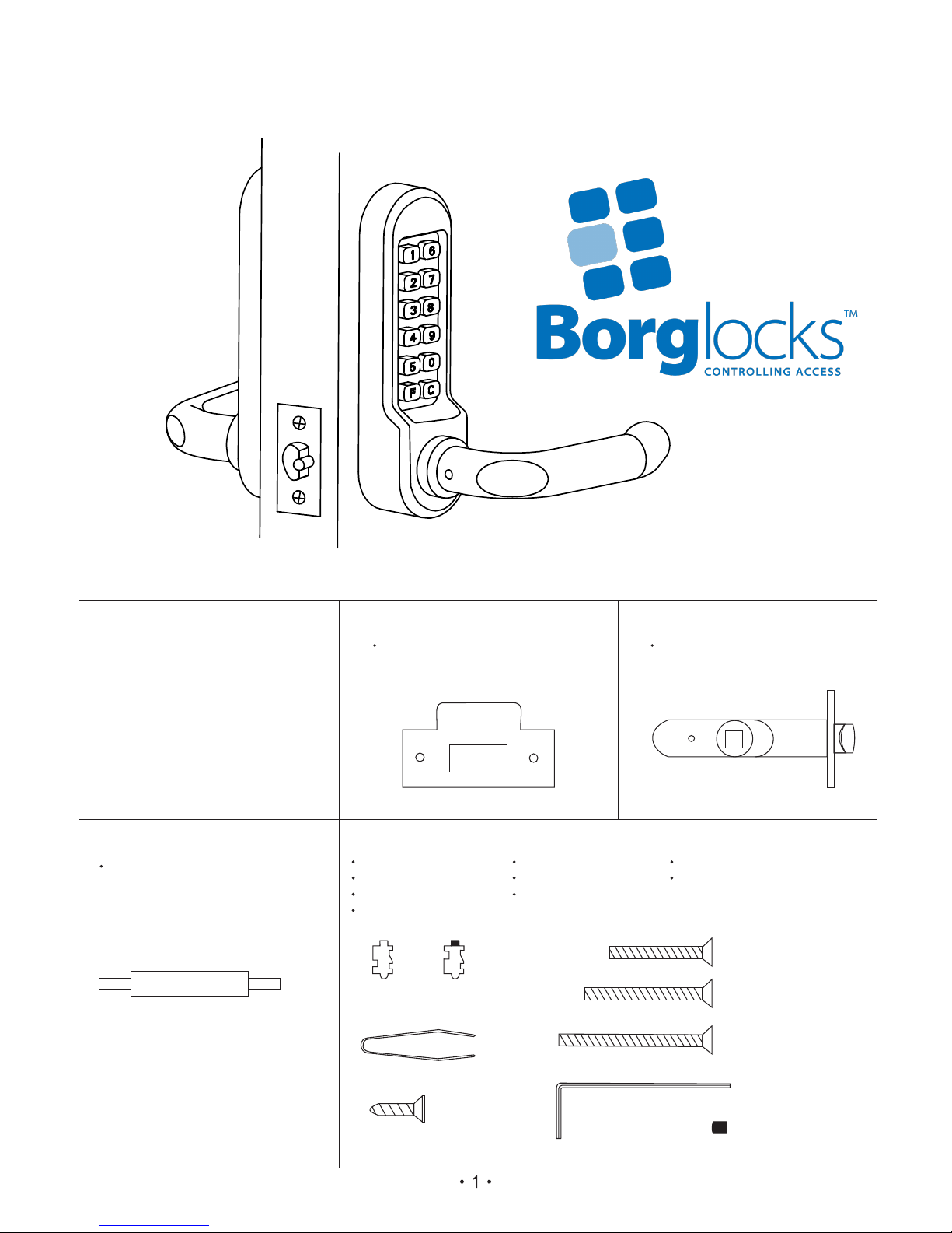
PARTS LIST
Please m
ake sure you have received
the following parts:
Outside lock mechani sm
Inside lock mechanism
Access
ories
in 4 packs
)
(
1
2
3
)
(
)
(
ACCESSORIES PACK 1
S tr i ke pla t e an d b o x kee p
ACCESSORIES PACK 3
ACCESSORIES PACK 4
2 Spindles
X
2 n on- cod e d tu m bler s
2 c oded tu m b l ers
1 Tw
eezer
4 4 1 6 mm scre ws
X
2 M 4 4 0 m m s c r ews
2 M 4 5 0 m m s c rews
2 M 4 6 0 mm s c r e w s
X
X
X
1 long h e x a g onal a l l e n key
1 handle s crew r
u b b er g
romme t
X
2
X
2
X
1
4
X
2
X
2
X
2
X
1
X
1
X
ACCESSORIES PACK 2
Latch (6 0 m m s tan d ar d )
Page 2
If y uo h
ave
encountered any problems then
please refer to the trouble shooting g uide, if this
doesn t help to solve your problem contact
the
Borg helpline for further
information and
assistance.
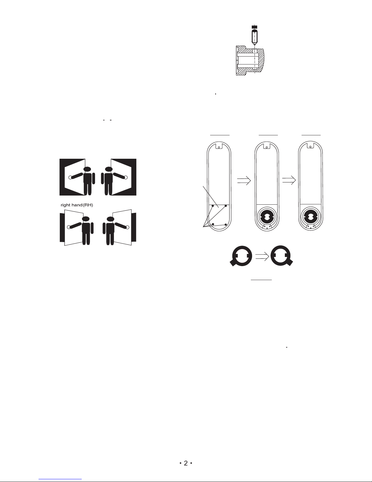
Tte lock is pre-set for right hand door. When
changing to a left hand door, please make sure the
following procedure is also carried out on the back
plate to prevent over-rotating of the inside handle.
INSTALLATION
PRIOR TO INSTALLATION
HANDING CHART
CHANGING TO A LEFT HAND HUNG
DOOR
INSIDE HANDLE
DIA.4
Please check the 5000 series lock is working
correctly, by entering the code as stated on the
printed code card (remembering to press“C”first
). Then rotate the handle clockwise, after rotating
0
approximately 45 you will h
ear a n audible click as
the tumblers engage. The handle
should then return
freely to the horizontal position.
(Always take hand from outside)
Hand of door
L
Hand of door
left hand(
H)
( LHR )
Hand of door
left hand reverse
Hand of door
right hand reverse
( RHR )
N. B. All units are set at the factory to suit right
hand hung doors
To change this unit to suit a left hand hung door
please follow the instructions below:
1. Remove the rubber grommet from the base of
the handle to expose the grub screw.
2. With the hexagonal key provided, remove the
grub screw that holds the handle in place.
O
3. Now you can lift
handle and turn it 180
off the
slide the handle back into position and refit the
grub screw and grommet.
4. Remove the 4 small screws that hold the spring
cassette to the handle.
5. Rotate the handle 180°
6. Ensure that the spring is located between the lugs
of the cassette and the lugs of housing.
7. Replace the 4 scr
ews ( to ensure that the screws
do not work loose during operation we
recommend you use a mild adhesive) .
DIA.1
DIA.2
DIA.3
1
2
ESTABLISH THE HAND OF THE DOOR
Viewing from the OUTSIDE it is right hand if the
e
hinges are
f
itted on th right and it is left hand if the
t
hinges are fit
ed on the left hand side of the door.
This is regardless of whether the door swings inward
or outward.
1. With the back side of the backplate facing you,
2
remove the cover (
) by unscrewing the 4
screws ( 1 ). ( DIA. 1
)
as in ( DI A.1 )
3. Fit the RING back as in ( DIA .4 )
4. Make sure the cover ( 3 ) is secured back in place
screws.
by the
4
2. Lift THE RING( 3 ) up and re position THERING
Page 3
The fixings supplied with the 5001 are the same as a
normal 5000 plus the following; 2×off-set spindle (1
right handed & 1 left handed),1 strike plate, 1 box
keep,1 60mm tubular latch & 1 brass support post.
For correct installation you will need to read the
following instructions carefully.
1. Mortise a hole (30 mm diameter 85mm deep) in
the edge of the door to take the tubular latch.
2. With the hole drilled, you will need to check that the
latch will slide in and out freely and operate wihtout
catching on the inside of the hole. Then you will
need to mark out the size of the faceplate on the
door, use a Stanley knife to do this to avoid splitting
when you chisel out a rebate to make the faceplate
flush with the door edge.
3. You will now need to drill the two small holes that will
accommodate the fixing posts and screws. Also you
will need to drill a hole to slot the spindle though. it
is very i m p ortant t h e holes ar e i n line, a s
mis alignment will cause the lock to malfunction or
even break up within a very short period. So please
take care to align these locks very carefully. To stop
the splitting and make the holes more accurate you
should drill the holes from both sides (not all the
way through)
4. The most important part of installing this lock is to
make sure that you have selected the correct
spindle. If uncertain, please refer to the handing
chart provided. Once you have the correct spindle,
you should assembly and install the spindle as
described earlier in this manual. At this point, you
should also screw in the brass support post. As this
part helps to keep the alignment of the unit and
latch once the unit has been installed. (You should
now follow the final installation instruction on page
2)
For any further detlils or information about you lock
please call the Borg Helpline on 0800 44 88 377
OTHER LOCKCASES
The 5000 can be fitted with other makes of
locks and lockcases, and we can provide special fixings
pack where necessary.
For more information and advice, please call our
help ine number.l
5. Now replace the covering panel and hand tighten
6. The code has now been changed, please check to
see that it is working correctly, also make a note
of the code for future reference. Once satisfied
that the lock is working as normal you are ready to
fit/re-fit the lock.
NOTES ABOUT THE CODE
You will have been provided with 4 spare tumblers
( 2 red and 2 blue ) these are to shorten or lengthen
your code.
N. B Your code can be entered in any order or
sequence e. g. 1234 or 4321 or 2431. There
are over 1,000 different combinations
avallable.
The button activates the code free entry feature, so if
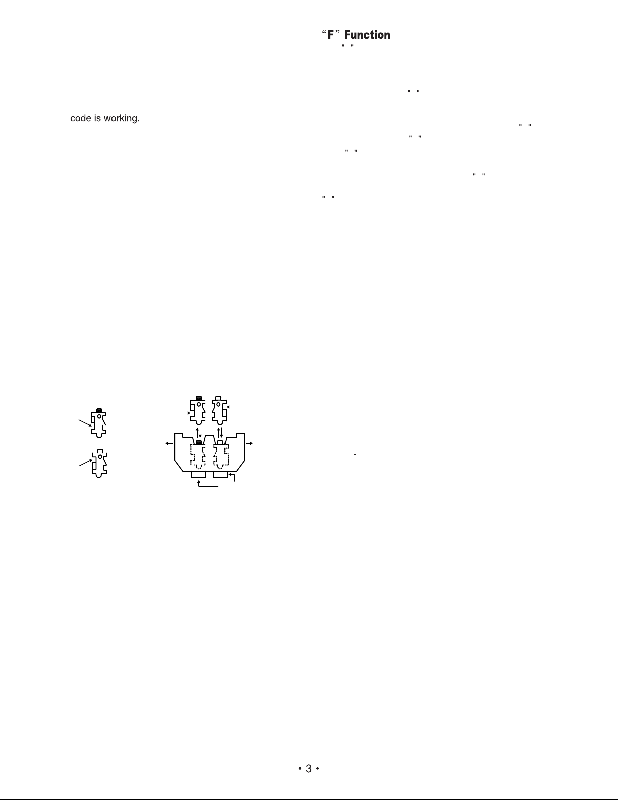
1. Firstly, you will need to check that the original
2. Turn the keypad over and remove the 4 red
screws.
3. You will now be able to lift off the covering panel (
please be careful as there are 12 springs attached
to this panel). Please note that the red tumblers
will relate to the code printed on the card
provided. Also note that the C tumbler is un coloured and is NOT to be removed.
4. To change your code you will now need to hold
the keypad face down, Next depress & hold the C
tumbler ( if this is not done you may damage
some of the internal components.) Now using the
tweezers provided, you can reposition the
tumblers to the code you want ( red tumblers are
coded and blue tumblers are uncoded). Please
ensure that the space cut-out on each tumbler is
facing the outside of the lock body, also make
sure that the coloured mark is facing upwards. If
any one tumbler is upside down or the wrong way
round the lock will not work and if forced will
break the internal components. Please note that
the code must always start with a C.
To change the code on this lock you will need to
follow the instructions below very carefully, as any
mistake may damage or cause the lock to
malfunction.
CODE CHANGING PROCEDURE
5001 INSTALLATION INSTRUCTIONS
you require continuous free passage you will need to
proceed as follows:
If the function is not required, it can be easily removed
by unscrewing the 4 red screws on the back of the keypad
to expose the tumblers. Depress the button and keep
it depressed, and using the tweezers provided to lift out the
tumbler. Now replace the metal cover and 4 red screws.
1 .Enter your access code, but before depressing the
lever press the button.
2. You will now be able to rotate the handle freely
without entering the code.
3. To cancel the free entry feature, press the button
followed by the button and this will reset the unit.
F
F
F
F
F
C
C
Square
cut-out
Red Coded
Tumbler
Buttons
Square
cut-out
Square
cut-out
Outwards
Square
cut-out
Blue Non-Coded
Tumbler
Outwards
Page 4

The lever cannot be
rotated after entering
a new code.
Clutch keeps breaking
out.
The latch bolt does
not move smoothly in
and out.
The lever is stiff after
changing the handing
of lock.
After changing the factory
code, one or more of the
coded tumblers are the wrong
way around.
The wrong type of lock case
is being used.
Grub screw may have been
over tightened.
The lock is not installed
correctly.
The lock case may be over sprung to suit non sprung
furniture. If double sprung, remove one of the springs.
O O
A MINIMUM of 40 ( preferable 45 ) travel is
required on the latch bolt to ensure smooth operation.
Check that the lock is square on the door and
positioned accurately over the lock case. Check that
the lock case is positioned horizontally and parallel to
spindle is too long it may be trapped between the front
and back plate.
If you have changed the handing of the lock then make
sure that the grub screw has not been over tightened:
If the outside lever is
dropping.
The lever has been forcibly
turned & the clutch has
broken out.
Someone may have tried to force entry or has entered
the wrong code and forced the lever to gain entry.
There is a clutch protection system that protects the
lock and the lock case from damage. If the handle is
dropping, then you will need to reset the clutch
mechanism by lifting the lever to the horizontal
position.
If this does not solve the problem please call our
technical support line on 0800 44 88 377.
If a Borg Lock should develop a fault due to manufacture within 1 years from date of purchase
it will be repaired free of charge.
DISCLAIMER. Under no circumstances should the lock be dismantled, as this will invalidate your
warranty.
Ltd.
Please Visit The Borg Locks
Website
fo r further
information @ WWW. BORGLOCKS.COM.
Installation Problems
Problem
Cause
After installation problems
Problems
Cause
Solution
Solution
Re-read the code change instruction and check that all
the tumblers have the square notches facing
outwards.
The Borg guarantee
Please call our helpline for spares, repairs and technical advice on 0800 44 88 377 Or E-mail:
Page 5
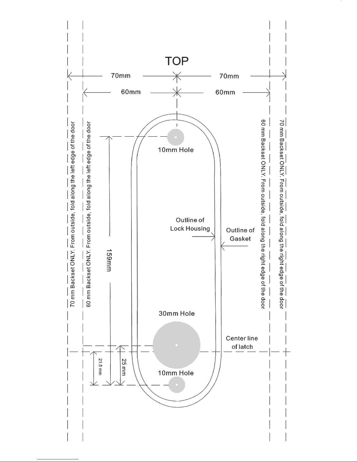
This drilling is to suit the following models : BL5201,BL5401BL5001,
This drilling is to suit the following models :BL5001,BL5201,BL5401
 Loading...