

Page 1
BL2400
Series Instruction Manual
Helpline: 0800 44 88 377
Contents
Problem Solving Guide
After Installation Problems
Guarantee: If your lock should develop a fault within 1 year from date of purchase, due to inferior
materials or workmanship the goods will be repaired or replaced free of charge.
Please call our helpline for spares, repairs and technical advice - UK: 0800 44 88 377
- International: +44 (0) 1708 225700
Disclaimer: Under no circumstances should the lock be dismantled, this will invalidate our warranty.
Problem Cause Solution
The latch cannot be withdrawn
when entering and turning the
knob.
The unit has been tted to a left hand
hung door.
All units are set to suit a right hand hung
door. The unit needs to be removed and
reversed. See `determing the hand of the
door’.
Both inside and outside knobs
retract when turned towards the
door frame.
The spindle has been set for the wrong
hand of door.
Remove the unit from the door and reposi-
tion the spindle. See ‘tting & positioning
the spindle’ (page no.4).
The latchbolt does not move
smoothly in and out.
The lock has not been installed
correctly.
Check the the hole for the spindle in the
back of the keypad and inside handle are in
alignment with the hole in the latch. Check
that the latch is positioned horizontally and
the forend of the latch is parallel to the door
edge. Also check the spindle length, it may
be too long and binding against the inside
handle or keypad spindle holes.
The keypad knob turns after entering a correct code but does not
retract the latch.
The knob will not turn after the
code has been changed.
One or more of the buttons in the code
have been programmed incorrectly.
Re-read ‘how to change your code number’
on (page no.7) and ensure that all of the
dials in the code are facing towards the
number down the centre.
The spindle has been cut too short or
has been positioned incorrectly.
If the spindle is too short it will not engage
with the keypad knob or inside handle. If
the spindle has been placed incorrectly
please refer to ‘tting & positioning the
spindle’ (page no.4).
Problem Cause Solution
The keypad knob turns freely without having to enter any code.
The knob has been forcibly turned without the correct code being entered.
Please call the Borg Locks helpline or return
the unit to Borg Locks or your distributor.
The inside handle lever does not
return to the upright position after
turning.
The handle return spring has broken. Please call the Borg Locks helpline or visit
our website for a replacment.
The latch does not engage with
the strike and the door remains in
the open position.
The latch is to entering the hole in the
strike plate.
Your door or frame may have warped since
the lock was installled. Check that the latchbolt is inline with the hole in the strike plate.
Re-align position of the stike if necessary.
Make sure the anti-thrust pin on the latch
does not enter the hole in the strike plate.
V2
Code Card
C####
Borg
locks
3
4
6
7
8
9
10
11 12 13
14
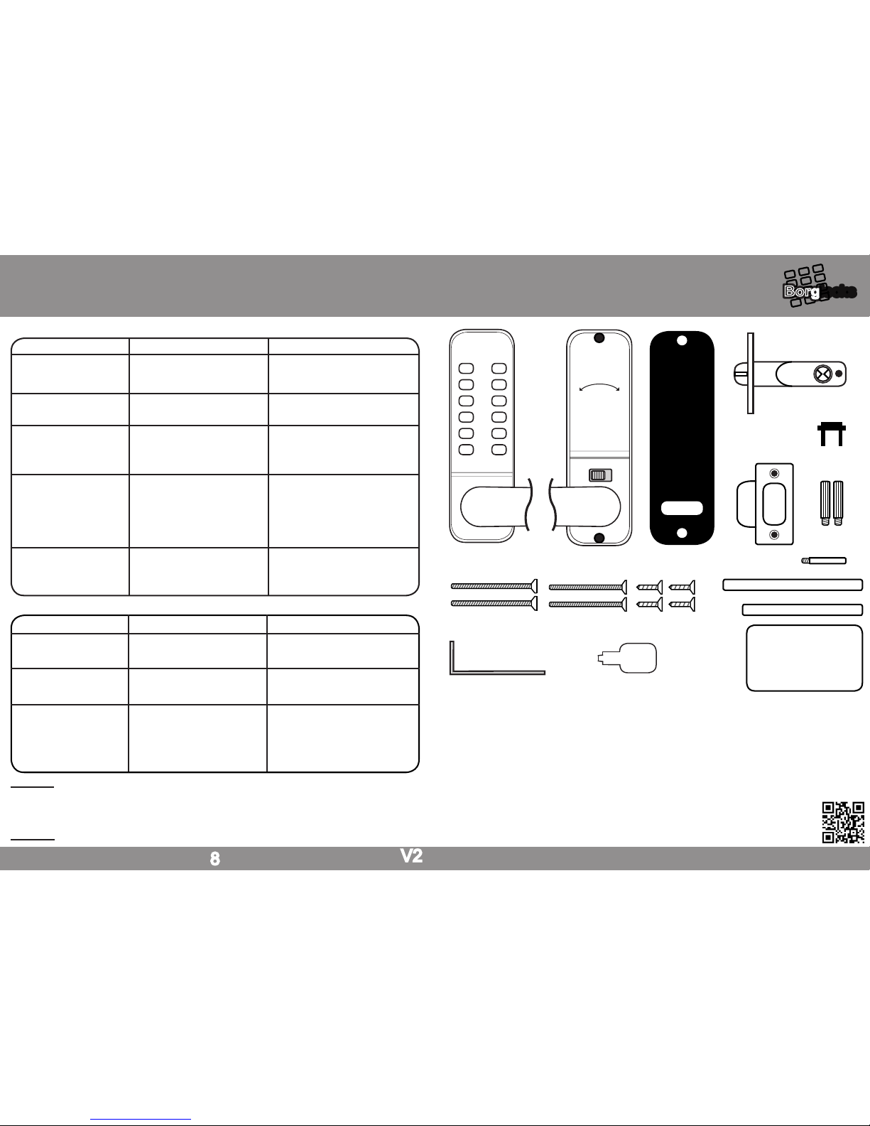
1. Keypad
2. Inside handle
3. Gaskets (x2)
4. Tubular Latch
5. Strike Plate & Box Keep
6. Holdback Snib Blank (Holdback Models Only)
7. Latch Support Post
8. Hexagon Support Posts
9. Spindle (100mm)
10. Spindle (85mm)
11. Machine Screws (50mm)
12. Machine Screws (35mm)
13. Wood Screws (15mm)
Installation Problems
www.borglocks.com
5
8
14. Code Card
1
borglocks.com
1 6
2 7
3 8
4 9
5 0
Y C
2
15. Allen Key
15
16. Code Change Tool
16
Page 2
2
Please check that all parts are working correctly. Enter the factory preset code as on the code card (part no.14), rotate the turn on the keypad one turn clockwise, re-enter the code and turn the knob anti-clockwise ensuring that the
follower on the back of the keypad rotates each time. The knob should return easily under its spring pressure. If you
intend to change the code please refer to ‘how to change your code number’ instructions (page no.7) prior to tting.
Make sure that the Inside handle device rotates freely and returns under its spring pressure.
Check that the latch bolt on the tubular latch (part no. 4) moves freely by pressing the bolt head at the end, and
also turning the spindle (part no. 9 or 10) in the hour glassed shaped follower on the locking device.
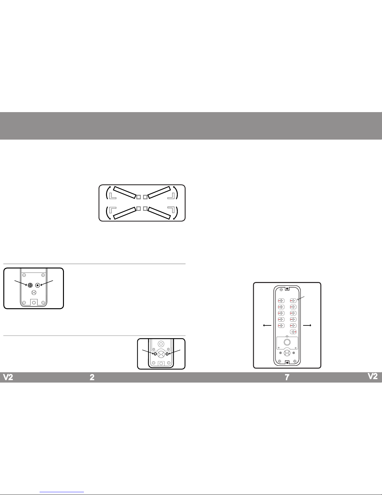
Determining the hand of the door
Many of the installation instructions refer to the handing
of the door. The hand of the door is determined with the
door in its closed position from the exterior or keypad
side of the door.
A) Right hand door – door opens inward (push), hinged
on the right side.
B) Left hand door – door opens inward (push), hinged
on the left side.
C) Right hand inward opening – door opens outward
(pull), hinged on the right side.
D) Left hand inward opening – door opens outward
(pull), hinged on the left side
Inside
Outside
A B
C
D
V2
Preparation
Fitting the Latch Support Post
Fit the latch support post (part no.7) in hole A for a right hand hung door or
B for a left hand hung door. Please refer to the ‘determining the hand of the
door’ if you are unsure what hand of door you have.
How To Change Your Code Number
Changing the Handing of the Unit
If the unit is being tted to a right hand hung door as per the ‘determining
the hand of the door’ nothing will need to be changed on the unit.
If the unit is being tted to a left hand hung door there are three parts
that would need to be changed. Firstly the blue handing screw on the
back of the inside handle will need to be moved from point A to point B
as per the diagram.
Finally both handles will need to be swapped around so that they are facing the opposite way. This is done by removing the rubber grommet from
the stem of the handle to reveal the grub screw. Using the allen key (part
no.15) remove the grub screw, this will allow the handle to come off from
its holder and be rotated the opposite way. Once the handles are facing
the correct way reinsert the grub screw and replace the rubber grommet.
A
B
1. Remove the lock from the door, which is done by removing the two screws at the very top and bottom of the inside handle.
2. Turn the keypad over so that you are able to see the code change dials on the reverse (as shown in the diagram below).
3. Press the ‘C’ button to ensure that no digits have been pressed.
4. Using the code change tool (part no.16) press and turn all of the code change dials outwards so that all of the red markers
on all of the code change dials are facing outwards.
Under no circumstances should any tool other than the code change tool (part no.16) to be used to turn the code
change dials.
5. To ensure that no digits have been entered, press the ‘C’ button and turn the knob on the keypad.
If the knob does not turn freely without having to enter any code, turn the keypad over and check that all of the red
markers on the code change dials are facing outwards.
6. To set a button as a coded digit the code change dial will need to be pressed and rotated using the code change tool (part
no.15) so that the red marker is facing towards the number or letter down the centre of the lock.
As you will see in the diagram below it has been coded to 1, 2, 3, 4, 5 as all of the red markers on the code change
dials are facing towards the numbers down the centre of the keypad and the remaining non coded digits are facing
outwards.
7. Ensure that all the remaining digits that are not in the code are facing outwards. As you will see from the diagram below the
digits that are not in the code 6, 7, 8, 9, 0 and Y have the red marker facing outwards and all of the coded digits red markers
are facing inwards towards the number down the centre of the keypad.
Please note that the code is not sequential and if for instance the unit was coded to 1, 2, 3, 4, 5 the code can be entered 5, 4, 3, 2, 1 or any sequence as long as all of the digits in the code have been pressed. It is recommended that
the ‘C’ button is pressed before each use to clear the coding chamber of any buttons that may have been pressed.
8. With the lock coded and a note made of the new code; enter the code and rotate the knob 3 - 4 times to check that the unit
has been recoded successfully before retting it to the door. Once tted to the door check the code once more before closing.
7
A B
6
7
8
9
0
C
1
2
3
4
5
Y
OutwardsOutwards
Code
Change Dial
V2
Page 3
Fitting the Hexagonal Support Posts
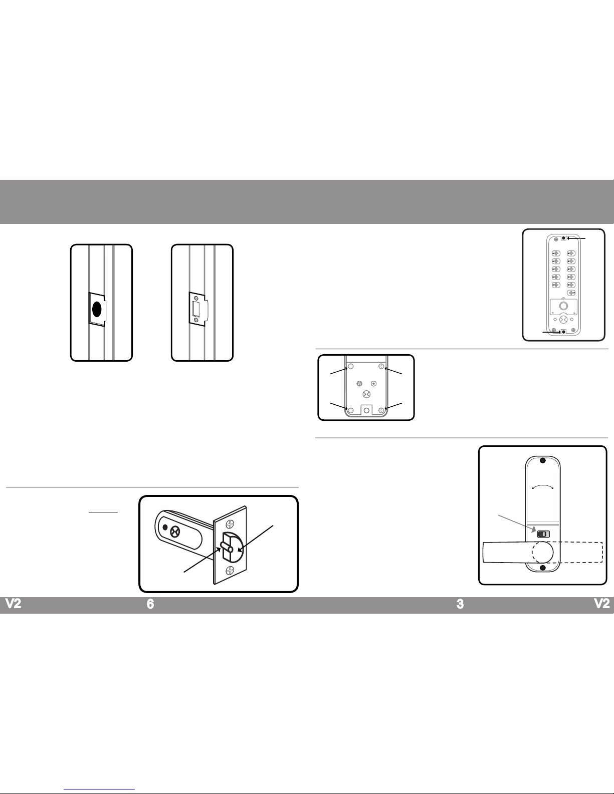
Fit both of the hexagonal support posts (part no.8) into the top and bottom
threaded holes of the keypad, as shown in the diagram.
Do not over tighten the hexagonal support posts as this may strip the
thread on either the post itself or the thread in the back of the keypad.
V2
3
Removing the Holdback Function
If you do not require the holdback function on the inside handle (holback
models model only) this feature can be removed.
On the back of the inside handle (part no. 2), unscrew all of the screws as
shown on points A, B, C and D on the diagram.
With the 4 screws removed the plate can now be lifted out of position, this
will reveal the holdback snib, which has a spring and ball bearing attached.
Remove the holdback snib, spring and ball bearing and place the hold back
snib blank (part no. 6) in the hole.
A
B
C D
V2
PreparationInstallation
6
Fitting the Strike Plate & Box Keep
Anti-Thrust Pin
Latchbolt
Push the door to the closed position and mark the area on the frame of the door where the strike plate would need
to be tted.
Open the door and now mark the inner and outer edges of the strike plate. Using a sharp chisel remove 1mm of
material from the frame of the door until the strike plate can sit ush.
With the material for the strike plate removed from the frame of the door, the material for the box keep will need to
be removed. Place the box keep in the cut-out made for the strike plate and draw around the box keep. You will
need to remove 36mm high, 23mm wide and 13mm deep of material to accommodate the box keep, alternatively a
20mm diameter by 15mm deep hole can be drilled in the frame to allow the latchbolt to fully protrude when the door
is in its closed position.
To secure the strike plate and box keep in place use two of the wood screws (part no. 13). Now that the strike and
the box keep have been secured in place the door can be closed. Ensure that the keypad and inside handle withdraw the latch when the door is in its closed position.
If the operation of the lock is excessively stiff when turning the keypad or inside handle, the strike plate
and box keep position will need to be adjusted.
Please note the anti-thrust beside the latchbolt (as
per the diagram), this deadlocks the latchbolt and
protects it against manipulation. It must not enter
the hole made for the latchbolt when the door is
closed.
If the anti-thrust pin does go into hole for the
latchbolt, adjust the position of the strike plate
until the anti-thrust pin sits on the face of the
strike plate.
Operating the Holdback Function
To operate the holdback function the handle will need be
turned a full 90° to the left or right (depending on the handing
of the door.
If the unit is tted to a left hand hung door the handle will need
to turned to the right (clockwise) and the snib will need to be
pushed to the left. When the snib has been pushed across the
handle will stay in the rotated position and the latchbolt in the
door will be withdrawn.
If the unit is tted to a right hand hung door the handle will
need to turned to the left (anticlockwise) and the snib will need
to be pushed to the right. When the snib has been pushed
across the handle will stay in the rotated position and the
latchbolt in the door will be withdrawn.
To release the holdback function a small amount of pressure
will need to be applied to the handle to allow you to push
the snib across. With the snib pushed across the handle will
spring back to its vertical position and the latchbolt in the door
will now be visible.
Holdback
Snib
A
B
6
7
8
9
0
C
1
2
3
4
5
Y
Page 4
4V2
Drilling the Door & Fixing the Latch
With all the drilling points marked out on the door, the holes can be drilled.
All of the 6 x 8mm holes will need to be drilled through the door. The remaining material which will be around the 4 x
8mm horizontal holes will need to be removed with a sharp chisel.
Where the ‘centre line of latch’ is marked on the template, drill a 25mm wide and 85mm deep hole in the edge of the
door to accommodate the barrel of the latch.
Insert the barrel of the latch into the hole in the edge of the door and draw around the rectangular face plate latch.
With the face plate marked, remove the latch from the hole in the door. Now remove 3mm of material from the door
so that the face plate of the latch sits ush with the door edge. With the latch positioned in the door it can now be
secured using two of the woods screws (part no. 13) via the two screw holes in the face plate of the latch.
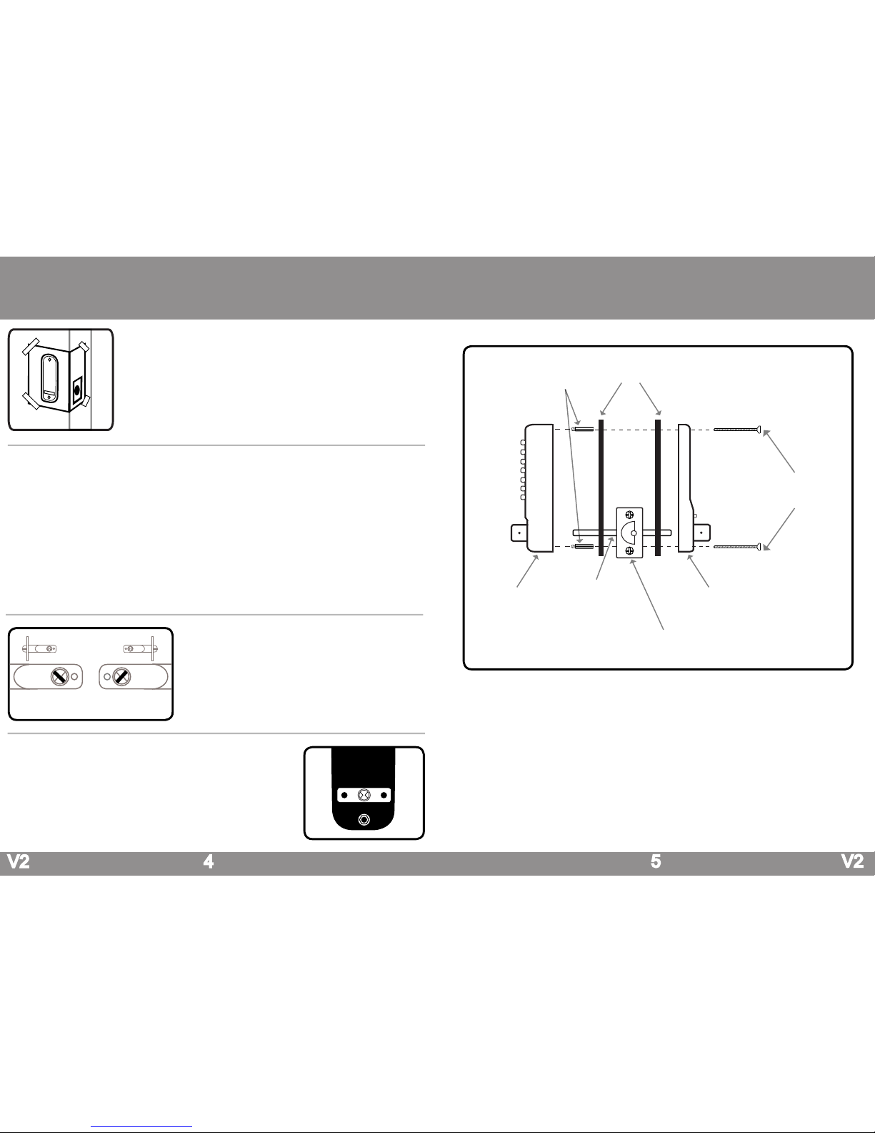
Apply the Drilling Template
Tape the template to the door and ensure that the dotted line on the template is
aligned to the edge of the door.
Mark all six of the 8mm holes as shown on the drilling template.
Mark on the door ‘centre line of latch’ ensuring that the centre line for the latch is in
the centre on the edge of the door.
Installation
Fitting & Positioning the Spindle
Select one of the two spindles (part no.9 - 100mm spindle) or
(part no. 10 - 85mm spindle) supplied in the accesory pack. Use
the longest spindle possible. Cutting the spindle down may be required, but this would depend entirely on the thickness of the door.
Please note if the spindle is cut too short this may cause the
spindle to slip out of possition if the door is slammed and
result in users being locked out.
Fitting the Keypad & Inside Handle
Place the larger of the two rubber gaskets (part no.3) around the back of the
keypad, ensuring that the gasket is the correct way up and that the spindle follower is still visible. As per the image.
The xing posts at the top and bottom on the reverse of the keypad will sit in
the very top and bottom 8mm holes drilled in the face of the door. When in
place ensure that the spindle is located into the spindle follower on back of the
keypad. Continued of page no.5.
5 V2
Place the smaller remaining rubber gasket (part no. 3) around the back of the inside handle and as with the keypad side the spindle follower on the back of the inside handle will need to be visible.
With the keypad in place on the door and the inside handle having the rubber gasket in place the inside handle
can be offered up to the door and secured in place using one pair of the machine screws (part no. 11 or 12). The
length of machine screw used would depend entirely on the thickness of the door.
Once the unit has been secured onto the door the unit can be tested on the set code. Check that both the keypad
and inside handle retract the latch fully.
Please note if the latch does not retract, the spindle has been put in the incorrect way. Please refer to ‘tting and
positioning the spindle’ on page no.4 as how to insert the spindle into the latch.
If the spindle is too short for the thickness of door, you will nd that you will only be able to retract the latch from
one side of the door and therefore you will need to remove and replace with a longer spindle.
If you nd the operation of the unit is very stiff when you are testing, either the unit has been over tightened on the
door and would need to be loosened or not enough material has been removed when drilling out the hole for the
barrell of the latch and therfore the unit will need to be taken off of the door and more material removed.
Installation
Fitting Illustration
Right Hand Left Hand
As viewed from the outside
of the door
Gaskets
(part no.3)
Keypad
(part no.1)
Inside Handle
(part no.2)
Machine Screws
(part no.11/12)
Hexagon Support
Posts (part no.8)
Spindle
(part no.9/10)
Tubular Latch (part no.4)
Secured in place with 2 wood screws (part no.13)
 Loading...