


UR06
Bopp und Reuther Messtechnik GmbH
Am Neuen Rheinhafen 4 – D-67346 Speyer
Phone +49 6232 657 - 0
Fax +49 6232 657 - 505
Internet: http://www.bopp-reuther.de
E-Mail : info@bopp-reuther.de
Dimensions, weights and other technical details
subject to change.
A-EN-08728-UR Rev.D
08/2016
Page 1 of 55
Universal Flow Computer UR06
Operating Manual

Universal Flow Computer UR06 Operating Manual
Page 2 of 55 Subject to changes A-EN-08728-URRev.B Bopp & Reuther
Messtechnik GmbH
Content
1 Identification ................................................................................................................................ 7
2 Area of Application ...................................................................................................................... 7
2.1 Intended use ..................................................................................................................... 7
2.2 Warning signs ................................................................................................................... 7
2.3 Operational safety ............................................................................................................ 7
2.4 Personnel for installation, start-up and operation ............................................................. 7
2.5 Factory setting .................................................................................................................. 7
2.6 Technical modifications .................................................................................................... 8
3 System Design ............................................................................................................................ 8
4 Input ............................................................................................................................................. 8
4.1 Measured variable ............................................................................................................ 8
5 Output .......................................................................................................................................... 9
5.1 Output signal..................................................................................................................... 9
5.2 Measuring transducer supply and auxiliary power ........................................................... 9
6 Characteristic Values .................................................................................................................. 9
6.1 Reference conditions ........................................................................................................ 9
6.2 Measuring uncertainty ...................................................................................................... 9
7 Operating Conditions ................................................................................................................. 10
7.1 Installation conditions ..................................................................................................... 10
7.1.1 Installation instructions ............................................................................................ 10
7.1.2 General information ................................................................................................. 10
7.1.3 Installation ............................................................................................................... 10
7.2 Ambient conditions ......................................................................................................... 10
7.2.1 Ambient temperature ............................................................................................... 10
7.2.2 Storage temperature ............................................................................................... 10
7.2.3 Climate class ........................................................................................................... 10
7.2.4 Mechanical class ..................................................................................................... 10
7.2.5 Degree of protection ................................................................................................ 10
7.2.6 Electromagnetic compatibility .................................................................................. 10
8 Constructive Design .................................................................................................................. 11
8.1 Model / Dimensions ........................................................................................................ 11
8.2 Weight ............................................................................................................................. 12
8.3 Material ........................................................................................................................... 12
9 Terminal Assignment ................................................................................................................. 12
9.1 Standard housing ........................................................................................................... 12
9.2 Plug-in unit ...................................................................................................................... 16
10 Connection of External Sensors ................................................................................................ 17
10.1 Active sensors ................................................................................................................ 17
10.2 Passive sensors ............................................................................................................. 17
10.3 Temperature sensors ..................................................................................................... 17
10.4 Active digital sensors ...................................................................................................... 18
10.5 2-channel active digital sensors (dual pulse) ................................................................. 18
10.6 Passive digital sensors ................................................................................................... 18
10.7 2-channel passive digital sensors (dual pulse) ............................................................... 19
11 Output Connection..................................................................................................................... 20
11.1 Current outputs ............................................................................................................... 20
11.2 Digital outputs ................................................................................................................. 20
11.3 Interfaces ........................................................................................................................ 20
12 Display and User Interface ........................................................................................................ 21
12.1 General information ........................................................................................................ 21
12.2 LC display ....................................................................................................................... 21
12.2.1 Display of measured values .................................................................................... 21
12.2.2 Display of parameter navigation .............................................................................. 22
12.2.3 Display of parameters ............................................................................................. 22
12.3 Operation ........................................................................................................................ 23
12.3.1 Key functions ........................................................................................................... 23

Operating Manual Universal Flow Computer UR06
Bopp & Reuther A-EN-08728-URRev.B Subject to changes Page 3 of 55
Messtechnik GmbH
12.3.2
Switching on the universal flow computer ................................................................ 23
12.3.3 Input examples ......................................................................................................... 24
13 Display Parameters .................................................................................................................... 27
14 Information ................................................................................................................................. 28
14.1 Time recording ................................................................................................................ 28
14.2 Flow computer ................................................................................................................. 28
14.3 Modules ........................................................................................................................... 28
15 Logbook ...................................................................................................................................... 29
15.1 Event log ......................................................................................................................... 29
15.2 Min/Max log ..................................................................................................................... 29
15.3 Parameter log .................................................................................................................. 29
15.4 Log book .......................................................................................................................... 29
15.4.1 Information ............................................................................................................... 29
15.4.2 Selection of displayed values ................................................................................... 29
15.4.3 Search for date ......................................................................................................... 30
15.4.4 Search for batch No. ................................................................................................ 30
16 Parameters ................................................................................................................................. 31
16.1 Parameter menu structure .............................................................................................. 31
16.1.1 Level 1 ...................................................................................................................... 31
16.1.2 Level 2 ...................................................................................................................... 31
16.1.3 Level 2 and 3 ............................................................................................................ 32
17 Parameter Description ............................................................................................................... 33
17.1 Passwords ....................................................................................................................... 33
17.1.1 Password L1 … L4 ................................................................................................... 33
17.2 Application ....................................................................................................................... 34
17.2.1 Basic application ...................................................................................................... 34
17.2.2 Language ................................................................................................................. 34
17.3 Error external ................................................................................................................... 34
17.3.1 Selection .................................................................................................................. 34
17.3.2 Input ......................................................................................................................... 34
17.4 Type label ........................................................................................................................ 34
17.4.1 Serial number ........................................................................................................... 34
17.4.2 TAG number ............................................................................................................. 35
17.4.3 Order number ........................................................................................................... 35
17.4.4 Customer .................................................................................................................. 35
17.4.5 Text 1 … 6 ................................................................................................................ 35
17.5 Display ............................................................................................................................. 35
17.5.1 Counters frame ........................................................................................................ 35
17.5.2 Line number ............................................................................................................. 35
17.5.3 Decimal places ......................................................................................................... 35
17.5.4 Units ......................................................................................................................... 35
17.5.5 Text .......................................................................................................................... 35
17.6 Primary transmitter / Secondary transmitter.................................................................... 36
17.6.1 Transmitter selection ................................................................................................ 36
17.6.2 Input ......................................................................................................................... 36
17.6.3 Nominal flow ............................................................................................................. 36
17.6.4 Pipe diameter ........................................................................................................... 36
17.6.5 Leak flow .................................................................................................................. 36
17.6.6 Place of installation .................................................................................................. 36
17.6.7 Event counters ......................................................................................................... 36
17.6.8 External control ........................................................................................................ 37
17.6.9 Pulse value ............................................................................................................... 37
17.6.10 Ratio X:Y .................................................................................................................. 37
17.6.11 Leak flow mode ........................................................................................................ 37
17.6.12 Calibration threshold ................................................................................................ 37
17.6.13 Residence time ........................................................................................................ 37
17.6.14 Basic pulses ............................................................................................................. 37
17.6.15 Error pulses .............................................................................................................. 37
17.6.16 Minimum measuring time ......................................................................................... 37
17.7 Orifice .............................................................................................................................. 38
17.7.1 Orifice type ............................................................................................................... 38
17.7.2 Flow coefficient ........................................................................................................ 38

Universal Flow Computer UR06 Operating Manual
Page 4 of 55 Subject to changes A-EN-08728-URRev.B Bopp & Reuther
Messtechnik GmbH
17.7.3
Flow rate factor ........................................................................................................ 38
17.7.4 Bore diameter .......................................................................................................... 38
17.7.5 TC pipe .................................................................................................................... 38
17.7.6 TC bore.................................................................................................................... 38
17.8 Linearization ................................................................................................................... 38
17.8.1 Linearization ............................................................................................................ 38
17.8.2 Table ........................................................................................................................ 39
17.9 Inputs .............................................................................................................................. 39
17.9.1 PT inputs ................................................................................................................. 39
17.9.2 Current input level ................................................................................................... 39
17.9.3 Digital input level ..................................................................................................... 39
17.10 Fluid ................................................................................................................................ 39
17.10.1 Fluid ......................................................................................................................... 39
17.10.2 Standard density ..................................................................................................... 39
17.10.3 Base pressure ......................................................................................................... 39
17.10.4 Base temperature .................................................................................................... 39
17.10.5 Isentropic exponent ................................................................................................. 40
17.10.6 Compressibility ........................................................................................................ 40
17.10.7 Saturated pressure monitor ..................................................................................... 40
17.10.8 Pressure reserve ..................................................................................................... 40
17.10.9 Dynamische Viskosität 0°C ..................................................................................... 40
17.10.10 Sutherland-Konstante .............................................................................................. 40
17.11 Redlich Kwong ................................................................................................................ 40
17.11.1 Critical pressure ...................................................................................................... 40
17.11.2 Critical temperature ................................................................................................. 40
17.12 Density ............................................................................................................................ 40
17.12.1 Density determination .............................................................................................. 40
17.12.2 Density input ............................................................................................................ 41
17.12.3 Density measuring parameter 0 … 1 ...................................................................... 41
17.12.4 Density default ......................................................................................................... 41
17.12.5 Density end ............................................................................................................. 41
17.12.6 Density start ............................................................................................................ 41
17.12.7 Temperature ............................................................................................................ 41
17.12.8 Oscillation fork ......................................................................................................... 41
17.13 Special fluid .................................................................................................................... 41
17.13.1 Parameter special fluid density ............................................................................... 41
17.13.2 Parameter special fluid dynamic viscosity ............................................................... 41
17.13.3 Parameter special fluid enthalpy ............................................................................. 42
17.14 Special fluid concentration .............................................................................................. 42
17.14.1 Mode ........................................................................................................................ 42
17.14.2 Input ......................................................................................................................... 42
17.14.3 Default ..................................................................................................................... 42
17.14.4 End value ................................................................................................................ 42
17.14.5 Start value ............................................................................................................... 42
17.14.6 Parameter ................................................................................................................ 42
17.15 GERG ............................................................................................................................. 42
17.15.1 GERG parameter .................................................................................................... 42
17.16 Mineral oils ...................................................................................................................... 42
17.16.1 Oil group .................................................................................................................. 42
17.16.2 Density 15°C ........................................................................................................... 43
17.16.3 Compressibility mode .............................................................................................. 43
17.16.4 vapor pressure mode .............................................................................................. 43
17.16.5 vapor pressure ........................................................................................................ 43
17.16.6 Antoine A, B, C ........................................................................................................ 43
17.17 Differential pressure ....................................................................................................... 43
17.17.1 dp mode .................................................................................................................. 44
17.17.2 dp default ................................................................................................................. 44
17.17.3 dp averaging ............................................................................................................ 44
17.17.4 dp offset ................................................................................................................... 44
17.17.5 dp1A/1B end ............................................................................................................ 44
17.17.6 dp1A/1B input .......................................................................................................... 44
17.18 Pressure ......................................................................................................................... 44

Operating Manual Universal Flow Computer UR06
Bopp & Reuther A-EN-08728-URRev.B Subject to changes Page 5 of 55
Messtechnik GmbH
17.18.1
Air pressure .............................................................................................................. 44
17.18.2 Pressure Q correction .............................................................................................. 44
17.18.3 Pressure mode 1 ... 3 ............................................................................................... 44
17.18.4 Default pressure 1 … 3 ............................................................................................ 45
17.18.5 End pressure 1 … 3 ................................................................................................. 45
17.18.6 Start pressure 1 … 3 ................................................................................................ 45
17.18.7 Offset pressure 1 … 3 .............................................................................................. 45
17.18.8 Pressure input .......................................................................................................... 45
17.19 Temperature .................................................................................................................... 45
17.19.1 Temperature mode 1 … 3 ........................................................................................ 45
17.19.2 Default temperature 1 … 3 ....................................................................................... 45
17.19.3 Temperature input .................................................................................................... 45
17.19.4 End temperature 1 ... 3 ............................................................................................ 45
17.19.5 Start temperature 1 ... 3 ........................................................................................... 45
17.20 Thresholds ....................................................................................................................... 46
17.20.1 Monitoring mode ...................................................................................................... 46
17.20.2 Grace period monitoring .......................................................................................... 46
17.20.3 Upper/Lower limit monitoring ................................................................................... 46
17.20.4 Gradient monitoring ................................................................................................. 46
17.20.5 Threshold selection 1 ... 7 ........................................................................................ 46
17.20.6 Top/Bottom threshold 1 ... 7 ..................................................................................... 46
17.21 Digital outputs .................................................................................................................. 47
17.21.1 Min. pulse width ....................................................................................................... 47
17.21.2 Digital output 1-3 mode 1-3 ...................................................................................... 47
17.21.3 Digital output 1 ... 3(7) ............................................................................................. 47
17.21.4 Pulse value digital output 1 ... 3(7) ........................................................................... 47
17.22 Current output ................................................................................................................. 47
17.22.1 Selection current output 1 ... 2(6) ............................................................................. 47
17.22.2 Default current output 1 ... 2(6) ................................................................................ 48
17.22.3 End current output 1 ... 2(6) ..................................................................................... 48
17.22.4 Start value current output 1 ... 2(6) .......................................................................... 48
17.22.5 Time constant current output 1 ... 2(6) ..................................................................... 48
17.22.6 Error behavior current output 1 ... 2(6)..................................................................... 48
17.22.7 Level current output 1 ... 2(6) ................................................................................... 48
17.23 Clock................................................................................................................................ 48
17.23.1 Date .......................................................................................................................... 48
17.23.2 Time ......................................................................................................................... 48
17.23.3 Clock adjustment...................................................................................................... 48
17.24 Data logger ...................................................................................................................... 49
17.24.1 Log events ................................................................................................................ 49
17.24.2 Record date 1 .. 2..................................................................................................... 49
17.24.3 Data log period ......................................................................................................... 49
17.24.4 Data log integration time .......................................................................................... 49
17.24.5 Data log configuration error comes/goes ................................................................. 49
17.24.6 Data log history days ............................................................................................... 49
17.24.7 Data log delete old entries ....................................................................................... 49
17.25 Communication ............................................................................................................... 49
17.25.1 Bus address M-Bus .................................................................................................. 49
17.25.2 M-Bus baud rate ....................................................................................................... 49
17.25.3 Secondary M-Bus address ....................................................................................... 49
17.25.4 M-Bus manufacturer ................................................................................................ 49
17.25.5 Modbus address ....................................................................................................... 50
17.25.6 RS232 mode ............................................................................................................ 50
17.25.7 Modbus baud rate .................................................................................................... 50
17.25.8 Modbus data bit ........................................................................................................ 50
17.25.9 Modbus parity ........................................................................................................... 50
17.25.10 Profibus .................................................................................................................... 50
17.25.11 Counter factor bus ................................................................................................... 50
17.26 Counters .......................................................................................................................... 50
17.26.1 AUX counters ........................................................................................................... 50
17.26.2 AUX mode ................................................................................................................ 50
17.26.3 AUX selection ........................................................................................................... 50

Universal Flow Computer UR06 Operating Manual
Page 6 of 55 Subject to changes A-EN-08728-URRev.B Bopp & Reuther
Messtechnik GmbH
17.26.4
Clear counters ......................................................................................................... 51
17.26.5 Set value counter .................................................................................................... 51
17.27 Balancing ........................................................................................................................ 51
17.27.1 PT100 balancing offset / slope 1 ... 2 ...................................................................... 51
17.27.2 PT500/1000 balancing offset / slope 1 ... 2 ............................................................. 51
17.27.3 Current input balancing offset / slope 1 ... 2 (6) ...................................................... 51
17.27.4 Current output balancing offset / slope 1 ... 2 (6) .................................................... 51
18 Connection of the Universal Flow Computer ............................................................................. 51
19 Certificates and Approvals ........................................................................................................ 52
20 Appendix .................................................................................................................................... 52
20.1 Error and warning messages .......................................................................................... 52
20.2 Units ................................................................................................................................ 54

Operating Manual Universal Flow Computer UR06
Bopp & Reuther A-EN-08728-URRev.B Subject to changes Page 7 of 55
Messtechnik GmbH
1 Identification
Manufacturer: Bopp & Reuther Messtechnik GmbH
Am Neuen Rheinhafen 4
67346 Speyer, Germany
Phone : +49 6232 657-0
Fax : +49 6232 657-505
Type of product: Universal flow computer
Product name: UR06
Version no.: A-EN-08728-UR Rev.D (UR06; hardware: HV4; software: V0.57 or higher)
2 Area of Application
2.1 Intended use
UR06 is designed to measure energy and flow rates for gaseous, vaporous and liquid media. Various
types of volume, mass, flow, pressure, temperature and density transmitters can be connected. The
measured values and the set parameters are used according to generally acknowledged rules of
technology to form the media data. In order to further process the measured and calculated values, it
is possible to transfer the data via variably configurable standard interfaces.
2.2 Warning signs
At the time of delivery, the universal flow computer UR06 meets the highest technical specifications
and is generally safe to operate. It has been tested and left the factory in perfect working order.
However, careless or incorrect usage of the universal flow computer can result in hazardous
situations.
Therefore, always observe the warning signs.
2.3 Operational safety
UR06 must not be used in explosive areas.
The universal flow computer UR06 meets the following safety criteria:
Safety requirements in accordance with EN 61010-1:2001
Interference stability in accordance with EN 61000-4-2, EN 61000-4-3, EN 61000-4-4,
EN 61000-4-5, EN 61000-4-6, EN 61000-4-8
Interference emit in accordance with EN 61326 Class A
Heat meters in accordance with EN 1434-4 Class C
Degree of protection provided by the housing IP 65 in accordance with EN 60529
Parameter and counter data is saved in the EEPROM during a power failure.
2.4 Personnel for installation, start-up and operation
Only trained personnel who have received authorization from the system owner are
allowed to carry out assembly, electrical installation, start-up, maintenance, and
operation. They should have read and understood the operating instructions and
always follow the information contained therein. Incorrect installation and start-up
can result in significant measuring errors or damage to the device.
Always adhere to national regulations.
Danger of death if the power supply is connected incorrectly.
2.5 Factory setting
The universal flow computer UR06 is supplied with a default configuration or set to the operating
conditions specified in the order.

Universal Flow Computer UR06 Operating Manual
Page 8 of 55 Subject to changes A-EN-08728-URRev.B Bopp & Reuther
Messtechnik GmbH
See the enclosed configuration data sheet for the set values.
Incorrect alterations to the parameters can result in measuring errors.
2.6 Technical modifications
In view of technical developments, Bopp & Reuther Messtechnik GmbH reserves the right to make
appropriate technical modifications without prior notice.
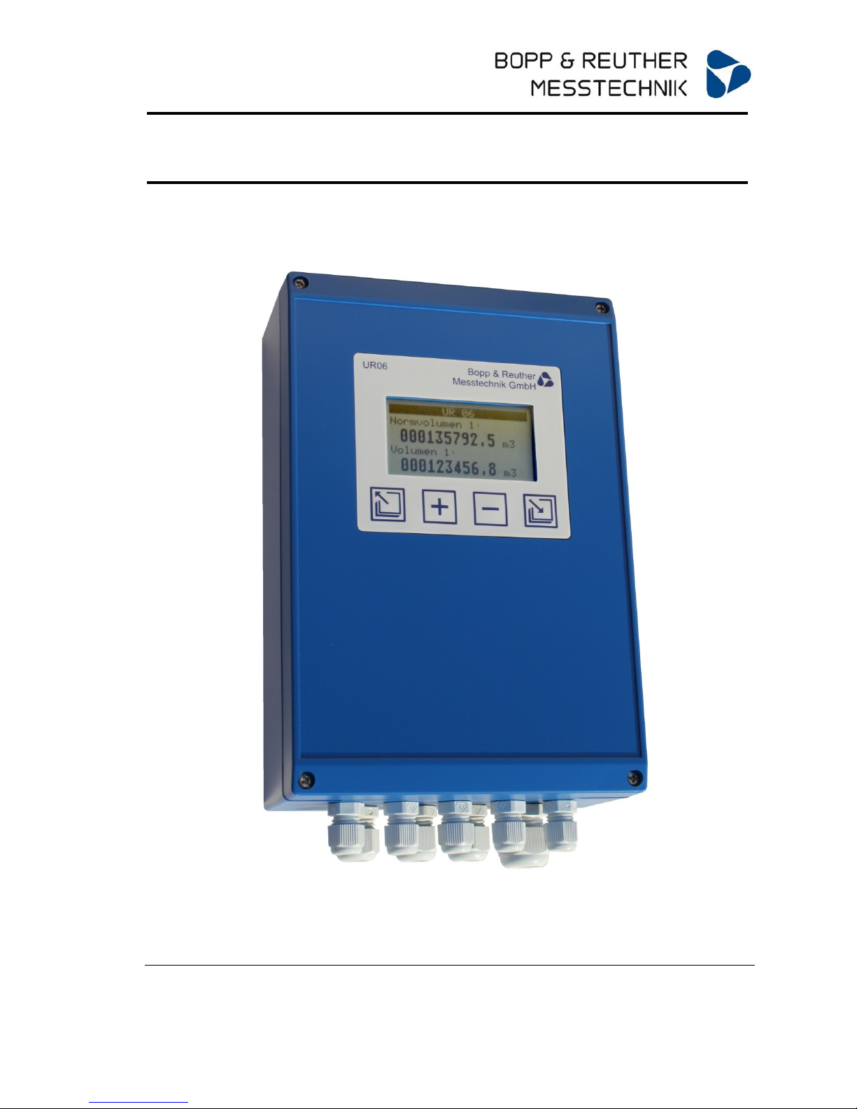
3 System Design
The universal flow computer UR06 is a state-of-the-art flow computer. UR06 has a graphical display,
which allows users to view all the relevant measuring and calculation values. Using the menu
guidance, it is possible to alter the configuration and parameters via the respective keys. Optional
input and output cards are available to enhance device functioning.
The universal flow computer consists of the following components:
Calculation unit with integrated inputs and outputs (basic module)
LC display unit with 4 keys
Input cards (optional)
Output cards (optional)
4 Input
4.1 Measured variable
Electrical measured variables:
Current, pulse, frequency, resistance, contact (status)
Physical measured variables:
Temperature, pressure, differential pressure, volume (flow), mass (flow), density
Special feature:
2 independent 24 Bit AD converters for resistance (temperature) and current.
Measured variable Input parameter
Resistance Model: PT 100, PT500, PT1000 4-wire measurement
Measuring ranges: -100 °C ... 600 °C
PT100: -100 °C ... 600 °C
PT500: -100 °C ... 500 °C
PT1000: -100 °C ... 300 °C
Overload protection: ± 24 V
Measuring uncertainty T: 0.1% of MV ± 0.1 K
Measuring uncertainty ΔT: 0.1% of MV ± 0.02 K
Temperature influence T: 0.0025% / K
Temperature influence ΔT: 0.0010% / K
Resolution: 24 Bit
Measuring rate: approx. 16 / s
Sensor break monitoring
Sensor current PT 100: approx. 1.8 mA
Sensor current PT 500 / 1000: approx. 0.7 mA
Current Measuring range: 0...22 mA
Overload protection: ± 24 V
Error detection 3.6 mA according to Namur NE43
Measuring uncertainty: 0.01% of MV ± 0.001 mA
Temperature influence: 0.0025% / K
Resolution: 24 Bit
Measuring rate: approx. 16 / s
Frequency
pulse
Status
Frequency measurement: 0.1 Hz ...15 kHz
Metering: 0 ... 15 kHz
Min. measuring time can be set: (0.1…10s)
Measuring uncertainty: 0.01% of MV
Temperature influence: 0.0025% / K
Resolution: 0.001% of MV

Operating Manual Universal Flow Computer UR06
Bopp & Reuther A-EN-08728-URRev.B Subject to changes Page 9 of 55
Messtechnik GmbH
Switchable hardware filter: Without, 50 Hz (for suppressing contact
bounces)
Active signals:
Passive signals: O.C, relay, Namur (U
0
approx. 8.5 V; IS approx. 1.4/1.8
mA)
5 Output
5.1 Output signal
Current, pulse, switching output/status, measuring transducer supply
Output variable Output parameter
Current Range: 0...22 mA, active
Max. load: 500 Ω (U0 approx. 12V)
Galvanic isolation among each other and to the basic device
Error signals: 3.5 mA and 22 mA according to NAMUR NE43
Accuracy: 0.02% of MV ± 0.002 mA
Temperature influence: 0.005% / K
Resolution: 16 Bit
Pulse / Status Type: Open collector, passive, galvanic isolated
Frequency range: 0 ... 100 Hz
Min. pulse width: 5 ms 500 ms
Overload protection: ± 24 V
Internal resistance 70 Ω
Residual voltage < 1.2 V
I
max
: 20 mA
U
ma
x
: 24 V
5.2 Measuring transducer supply and auxiliary power
Output variable Output parameter
Measuring transducer
supply (MUS)
Voltage: 24 V DC
Current: Max. 30 mA, short circuit proof
Auxiliary power
Voltage: 24 V DC
Current: Max. 250 mA, short circuit proof
6 Characteristic Values
6.1 Reference conditions
Voltage supply: 230 VAC ±10%, 50 Hz ±0.5 Hz
Warm-up time: 10 min
Ambient temperature: 25°C ±5°C
Humidity: 39% ±10% r. h.
6.2 Measuring uncertainty
see 4.1

Universal Flow Computer UR06 Operating Manual
Page 10 of 55 Subject to changes A-EN-08728-URRev.B Bopp & Reuther
Messtechnik GmbH
7 Operating Conditions
7.1 Installation conditions
7.1.1 Installation instructions
Please read the operating instructions carefully prior to installation and start-up.
7.1.2 General information
Observe operating data marked on the housing. Also observe data in the order confirmation and on
the data sheet. If you wish to use the device under different operating conditions, consult the
manufacturer in advance, and always state the serial number.
7.1.3 Installation
Various installations are possible:
Housing with LCD for wall installation
Housing without LCD for wall installation and separate LCD housing
Housing for cabinet installation and separate installation of the LCD in the cabinet door
Plug-in unit design
7.2 Ambient conditions
7.2.1 Ambient temperature
0°C to +55°C
7.2.2 Storage temperature
-30°C to +70°C
7.2.3 Climate class
In accordance with EN 1434 Class C
7.2.4 Mechanical class
In accordance with EU directive 2004/22/EC Class M1
7.2.5 Degree of protection
IP65 IEC 529 / EN 60529 (wall installation in plastic housing)
IP65 for separate flow computer installation (with closed additional cover), IP20 for
cover with display and keys.
IP20 19” plug-in unit
7.2.6 Electromagnetic compatibility
Interference emit:
EN 61326 Class A
Interference stability:
Power failure: 20 ms, no influence
Electromagnetic fields: 10 V/m (80 ... 2700 MHz ) in accordance with EN 61000-4-3
Electromagnetic fields: 30 V/m (800 ... 2,000 MHz ) in accordance with EN 61000-4-3
Conducted HF: 0.15 to 80 MHz, 10 V in accordance with EN 61000-4-6
Electrostatic discharge: 6 kV contact / 8 kV indirect in accordance with EN 61000-4-2
Burst (AC and DC supply): 4 kV in accordance with EN 61000-4-4
Burst (signal): 1 kV / 2 kV in accordance with EN 61000-4-4
Surge (AC and DC supply): 1 kV / 2 kV in accordance with EN 61000-4-5
Surge (signal): 500 V / 1 kV in accordance with EN 61000-4-5
EN1434-4 Class C
In accordance with EU directive 2004/22/EC Class E2
Operating Manual Universal Flow Computer UR06
Bopp & Reuther A-EN-08728-URRev.B Subject to changes Page 11 of 55
Messtechnik GmbH
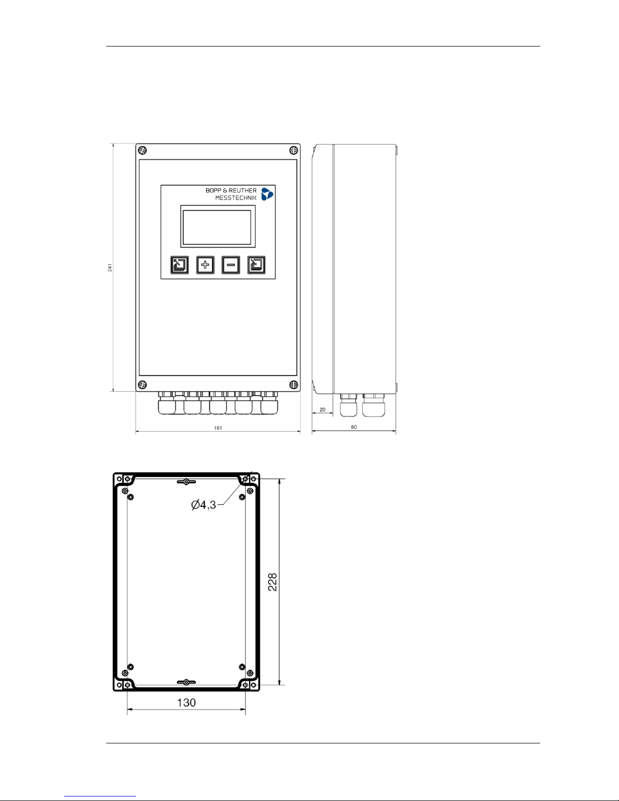
8 Constructive Design
8.1 Model / Dimensions
1. Standard plastic housing
Front view:
Wall installation:
Universal Flow Computer UR06 Operating Manual
Page 12 of 55 Subject to changes A-EN-08728-URRev.B Bopp & Reuther
Messtechnik GmbH
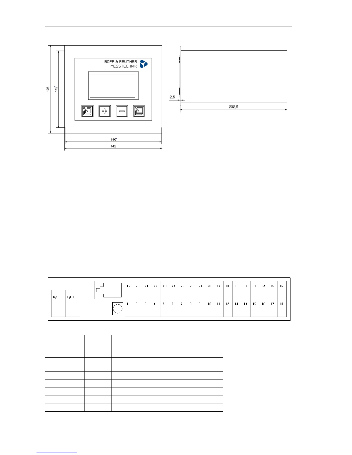
2. Plug-in unit
Front view:
All dimensions in mm
8.2 Weight
Standard: Approx. 1 kg
Plug-in unit: Approx. 1.5 kg
8.3 Material
Standard: ABS -40°C to 80°C, halogen-free
Plug-in unit: Aluminum
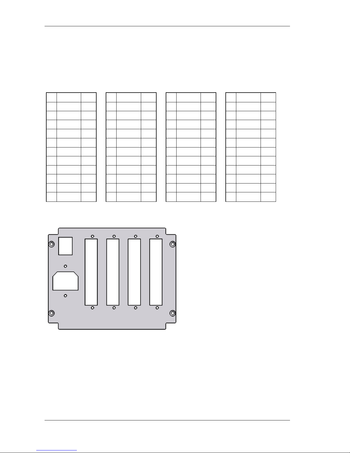
9 Terminal Assignment
9.1 Standard housing
UR06 in the standard housing has 36 double-row terminals; connection to the display occurs via a
western plug. All terminal descriptions relate to hardware version HV3.
Terminals of the basic device
Designation No. Function
N \ L- Neutral conductor 230 V AC
Minus 24 V DC
L \ L+ Phase 230 V AC
Plus 24 V DC
Disp. 24V Western Display supply voltage
Disp. GND Western Display supply voltage
Disp. RxD Western Serial interface to the display; receive
Disp. TxD Western Serial interface to the display; transmit

Operating Manual Universal Flow Computer UR06
Bopp & Reuther A-EN-08728-URRev.B Subject to changes Page 13 of 55
Messtechnik GmbH
M-Bus 1 M-Bus interface
M-Bus 2 M-Bus interface
3 Not occupied
RS232 RxD 19 Serial interface (Modbus); receive
RS232 TxD 20 Serial interface (Modbus); transmit
RS232 GND 21 Serial interface (Modbus); ground
OC 1 + 4 Digital output, open collector
OC 1 - 5 Digital output, open collector
OC 2 + 6 Digital output, open collector
OC 2 - 7 Digital output, open collector
OC 3 + 8 Digital output, open collector
OC 3 - 9 Digital output, open collector
Iout 1 + 22 Current output, galvanic isolated, active
Iout 1 - 23 Current output, galvanic isolated, active
Iout 2 + 24 Current output, galvanic isolated, active
Iout 2 - 25 Current output, galvanic isolated, active
DI 1 + 26 Digital input, (pulse, frequency, status)
DI 1 - 27 Digital input, (pulse, frequency, status)
DI 2 + 28 Digital input, (pulse, frequency, status)
DI 2 - 29 Digital input, (pulse, frequency, status)
Ex 24 V + 10 Auxiliary power for measuring head, galvanic
isolated, 24 V
Ex 24 V - 11 Auxiliary power for measuring head, galvanic
isolated, 24 V
MUS 1 12 Measuring transducer supply, 24 V, 30 mA
I1 13 Current input
GND 14 Current input 1 ground
MUS 2 30 Measuring transducer supply, 24 V, 30 mA
I2 31 Current input
GND 32 Current input 2 ground
PT1 ++ 15 PT 100/500/1000 input, supply
PT1 + 16 PT 100/500/1000 input, Sense
PT1 - 17 PT 100/500/1000 input, Sense
PT1 -- 18 PT 100/500/1000 input, supply
PT2 ++ 33 PT 100/500/1000 input, supply
PT2 + 34 PT 100/500/1000 input, Sense
PT2 - 35 PT 100/500/1000 input, Sense
PT2 -- 36 PT 100/500/1000 input, supply
Terminal assignment display
Universal Flow Computer UR06 Operating Manual
Page 14 of 55 Subject to changes A-EN-08728-URRev.B Bopp & Reuther
Messtechnik GmbH
The connection between the basic device and the display occurs via a cable with a western plug RJ10
at each end.
Terminal assignment modules
Module I-OUT
Designation No. Function
OC 1 + 1 Digital output, open collector
OC 1 - 2 Digital output, open collector
OC 2 + 3 Digital output, open collector
OC 2 - 4 Digital output, open collector
Iout 1 + 5 Current output, galvanic isolated, active
Iout 1 - 6 Current output, galvanic isolated, active
Iout 2 + 7 Current output, galvanic isolated, active
Iout 2 - 8 Current output, galvanic isolated, active
Module I-IN
Designation No. Function
MUS 3 1 Measuring transducer supply, 24 V, 30 mA
I3 2 Current input
GND 3 Current input 3 ground
MUS 4 4 Measuring transducer supply, 24 V, 30 mA
I4 5 Current input
GND 6 Current input 4 ground
Module pulse input
Designation No. Function
DI 3 + 1 Digital input, (pulse, frequency, status)
DI 3 - 2 GND
DI 4 + 3 Digital input, (pulse, frequency, status)
DI 4 - 4 GND
DI 5 + 5 Digital input, (pulse, frequency, status)
DI 5 - 6 GND
DI 6 + 7 Digital input, (pulse, frequency, status)
DI 7 - 8 GND
M
o
d
u
l
D
i
s
p
l
a
y
V
3

Operating Manual Universal Flow Computer UR06
Bopp & Reuther A-EN-08728-URRev.B Subject to changes Page 15 of 55
Messtechnik GmbH
Module M-Bus
Designation No. Function
Tx 1 Serial interface; transmit
Rx 2 Serial interface; receive
GND 3 Serial interface; ground (internal connected)
4
M + 5 M-Bus +
M + 6 Connected to terminal 5
M - 7 M-Bus -
M - 8 Connected to terminal 7
Module RS485
Designation No. Function
Tx 1 Serial interface; transmit
Rx 2 Serial interface; receive
GND 3 Serial interface; ground (internal connected)
4
5
A 6 RS485 galvanic isolated
B 7 RS485 galvanic isolated
GND* 8 GND galvanic isolated
Module Ethernet
Designation No. Function
Tx 1 Serial interface; transmit
Rx 2 Serial interface; receive
Ethernet RJ45 Ethernet
Universal Flow Computer UR06 Operating Manual
Page 16 of 55 Subject to changes A-EN-08728-URRev.B Bopp & Reuther
Messtechnik GmbH
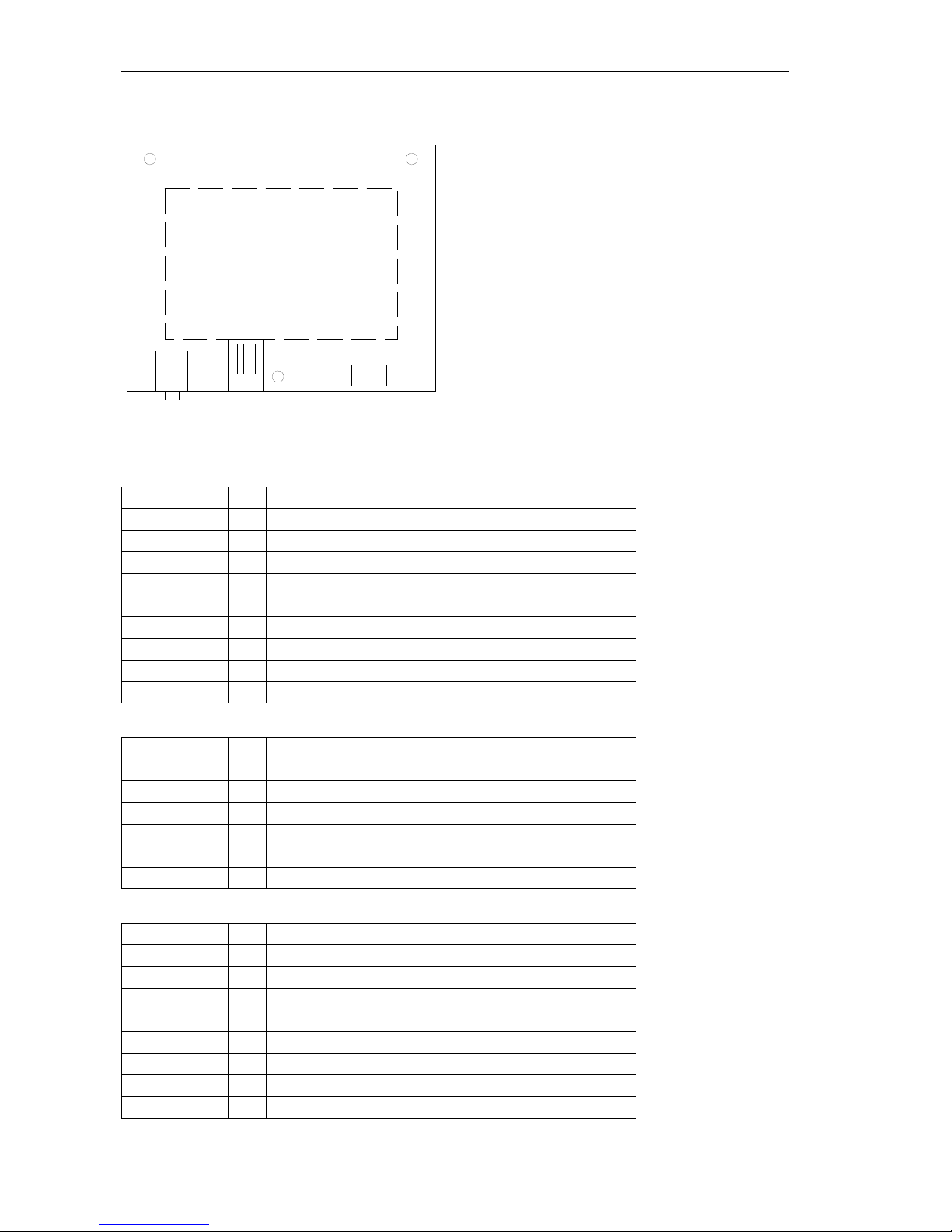
9.2 Plug-in unit
The UR06 plug-in unit has 3 - 4 removable 12-pole terminal blocks at the rear for the signal inputs and
outputs. Energy is supplied via an IEC connector (230 V). There is an additional socket (3.5 mm jack)
at the front for communication.
Terminal assignment:
J4 J3 J2 J1
1 1 OC 1+ 4 1 MUS1 12 1 DI 1 + 26
2 2 OC 1- 5 2 I1 13 2 DI 1 - 27
3 3 OC 2+ 6 3 GND 14 3 DI 2 + 28
4 4 OC 2- 7 4 MUS2 30 4 DI 2 - 29
5 5 OC 3+ 8 5 I2 31 5 PT1 ++ 15
6 6 OC 3- 9 6 GND 32 6 PT1 + 16
7 7 7 Iout1 +
22
7 PT1 - 17
8 8 M-Bus 1 8 Iout1 -
23
8PT1 -- 18
9 9 M-Bus 2 9 Iout2 +
24
9PT2 ++ 33
10 10 RS RxD 19 10 Iout2 - 25 10 PT2 + 34
11 11 RS TxD
20
11 24 V+ 10 11 PT2 - 35
12 12 RS GND
21
12 24 V- 11 12 PT2 -- 36
The numbers in the 3rd terminal block column relate to the terminal assignment of the standard
version. Terminal designations that start with the letter M relate to the module terminals.
J4 J3 J2 J1
Operating Manual Universal Flow Computer UR06
Bopp & Reuther A-EN-08728-URRev.B Subject to changes Page 17 of 55
Messtechnik GmbH
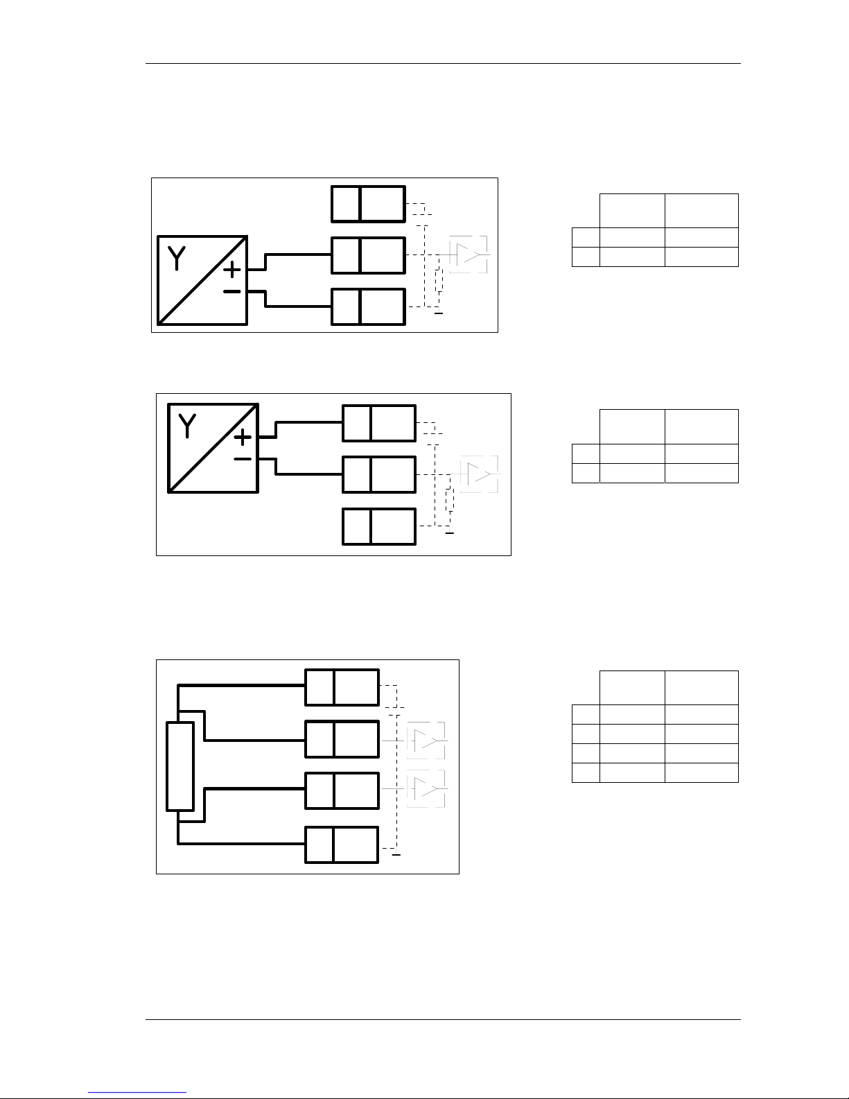
10 Connection of External Sensors
10.1 Active sensors
Connection of sensors which have an individual power supply and an active output.
Terminal Alternative
terminals
X2 13 31
X3 14 32
10.2 Passive sensors
Connection of sensors which do not have a power supply (2-wire transmitter).
Terminal Alternative
terminals
X1 12 30
X2 13 31
10.3 Temperature sensors
Connection of temperature sensors (PT100, PT500, PT1000). The terminals X1-X2 and X3-X4 must
be bridged when connecting 2-wire sensors.
The input has to be configured via the software.
Terminal Alternative
terminals
X1 15 33
X2 16 34
X3 17 35
X4 18 36
24V
X1
X3
X2
24V
X1
X3
X2
X1
X3
X2
X4
 Loading...