

Page 1

THT-100
Full Height Turnstile
Operation, Installation and Maintenance Manual
Page 2

1
Installation and Maintenance Manual
TABLE OF CONTENTS
GENERAL INFORMATION ................................................................................................... 3
1 Introduction ................................................................................................................... 3
1.1 C
1.2 L
1.3 P
1.4 P
1.5 A
1.6 S
2 Product Safety ............................................................................................................... 4
2.1 I
2.2 O
3 Product description ...................................................................................................... 6
3.1 G
3.2 S
3.3 B
3.4 C
3.5 R
3.6 R
3.7 T
3.8 C
3.9 S
4 Operating concept ...................................................................................................... 14
4.1 O
4.2 A
4.3 S
4.4 O
INSTALLATION .................................................................................................................. 19
5 Installation procedure ................................................................................................. 19
5.1 P
5.2 T
5.3 B
5.4 A
5.5 A
5.6 F
5.7 M
5.8 E
5.9 M
5.10 C
5.11 G
5.12 T
5.13 S
6 Parts Overview ............................................................................................................ 36
6.1 THT100- E
Safety INSPECTIONS and MAINTENANCE ...................................................................... 37
7 Safety Inspections ...................................................................................................... 37
7.1 D
8 Maintenance ................................................................................................................ 37
8.1 W
8.2 S
8.3 M
9 Troubleshooting .......................................................................................................... 40
Version : 10//28/2011
Issue : THT-100-IMM-USA REV A6
OPYRIGHT
IABILITY
RODUCT MODIFICATIONS
RODUCT OPTIONS
BBREVIATIONS
YMBOLS
NSTALLATION AND MAINTENANCE SAFETY
PERATIONAL SAFETY
ENERAL
HIELD OPTIONS
ARRIER ASSEMBLY OPTIONS
EILING PLATE
OTOR ARM OPTIONS
OTOR INFILL COVERS (OPTION
OP CHANEL COVER OPTIONS
ONTROL SYSTEM
PEED CONTROL UNIT
PERATING FUNCTIONS
CCESS CONTROL SYSTEM
ECURITY
PTIONAL AND CONFIGURATION FEATURES
ACKAGING AND CRATING
OOL AND MANPOWER LIST
OLT TORQUE SPECIFICATIONS
NCHOR TECHNIQUES
NCHOR LOCATIONS
LOOR LAYOUT
ECHANICAL ASSEMBLY
LECTRICAL INSTALLATION
AIN CONTROL BOX
ONFIGURATION
ENERAL
IME OUT RELAY ADJUSTMENT
PEED CONTROL ADJUSTMENT (OPTIONAL
AILY INSPECTION
EEKLY CLEANING
EMI-ANNUAL PLANNED MAINTENANCE
AINTENANCE CHECKLIST
................................................................................................................................ 3
.................................................................................................................................... 3
........................................................................................................... 3
..................................................................................................................... 4
.......................................................................................................................... 4
................................................................................................................................... 4
................................................................................................................ 5
................................................................................................................................... 6
........................................................................................................................ 7
..................................................................................................... 8
........................................................................................................................... 8
................................................................................................................ 9
) .............................................................................................. 10
.................................................................................................. 10
.................................................................................................................... 12
.............................................................................................................. 13
............................................................................................................ 14
(ACS) ............................................................................................. 15
................................................................................................................................ 15
......................................................................................................... 19
...................................................................................................... 20
................................................................................................ 20
.............................................................................................................. 20
................................................................................................................. 21
......................................................................................................................... 22
........................................................................................................... 23
........................................................................................................ 30
................................................................................................................. 31
....................................................................................................................... 34
................................................................................................................................. 35
................................................................................................. 35
XPLODED VIEW
....................................................................................................... 36
.................................................................................................................... 37
................................................................................................................... 37
..................................................................................... 37
......................................................................................................... 39
................................................................................... 4
............................................................................... 16
) .............................................................................. 35
Page 3

THT-100
9.1 C
9.2 T
9.3 R
ONTROL BOX AND MAIN CONTROL BOARD
OP CHANNEL MECHANISM
OTOR ASSEMBLY AND FRAME
....................................................................................................... 40
................................................................................................. 40
2
............................................................................... 40
TECHNICAL SPECIFICATIONS ......................................................................................... 41
10 Technical specifications ............................................................................................. 41
10.1 C
10.2 S
10.3 C
ONTROL
OLENOIDS
OMPLETE BARRIER
................................................................................................................................. 41
.............................................................................................................................. 41
................................................................................................................. 41
APPENDICES ..................................................................................................................... 42
11 Appendices ................................................................................................................. 42
11.1 S
11.2 E
11.3 THT100- T
11.4 TASTG – C
11.5 THT-100TL – T
PARE PART LIST
LECTRICAL SCHEMATICS
..................................................................................................................... 42
ANDEM UNIT
URVED SHIELD TANDEM UNIT
ANDEM UNIT
............................................................................................................ 44
......................................................................................................... 43
.................................................................................. 45
. .................................................................................................... 45
Enclosures ......................................................................................................................... 46
Boon Edam Inc.
402 McKinney Parkway Version: Rev A6 10/28//2011
Tel. 910-814-3800 fax 910-814-3899 Issue: THT-100-IMM-USA
Page 4

3
Boon Edam Inc.
Boo
n Edam B.V.
Beijing Boon Edam Entrance
Installation and Maintenance Manual
GENERAL INFORMATION
1 Introduction
This manual is written for the service and installation engineer, it provides information about:
• Operating the Product
• Installing the Product
• Electrical characteristics of the Product
• Maintenance on the Product
Please read this manual carefully, it contains information that will assist you with all aspects of
installation and maintenance, including operation of electrical parts, so that a long and useful
machine life can be achieved.
This manual has been written with the maximum care and attention. Nevertheless, if certain
parts are unclear to you or contain errors, you can contact the Boon Edam manufacturing
facilities.
402 McKinney Parkway
Lillington North Carolina 27546
United States of America
T +1 (910) 814 3800
F +1 (910) 814 3899
Ambachtstraat 4
1135 GG Edam
The Netherlands
T +31 (0)299 380808
F +31 (0)299 372859
Technology Co. Ltd
No.10 Tong Ji Bei Lu
Beijing Economic & Technological
Development Area
Beijing 100176 China
T +86 (0)10 67877766
F +86 (0)10 67877805
1.1
Copyright
This manual was prepared and issued by Boon Edam. All rights are reserved. The information
in this manual is property of Boon Edam. Disclosure of this information or any part of it to third
parties is not permitted, except with prior and express written permission of Boon Edam.
1.2 Liability
The product is designed, tested and produced in accordance with strict international regulations.
Correct operation can only be assured when regular maintenance is undertaken annually
(subject to frequency of use) by Boon Edam or an approved agent. For replacement, original
parts should be used, so that a correct operation is guaranteed. The warranty on the product will
end prematurely if the product is installed or maintained by unapproved engineers.
1.3 Product modifications
Boon Edam makes every effort to ensure that this manual is reviewed whenever significant
changes are made to the design. However, Boon Edam has the reserved rights to improve
products without notice. Therefore it is possible that the installed products show some
differences with the description in this manual.
Version : 10//28/2011
Issue : THT-100-IMM-USA REV A6
Page 5
THT-100
•
•
•
•
•
•
•
•
•
•
4
1.4 Product options
The options of the product are marked with an asterisk (*) in the text of this manual. The options
that are actually included on the product manufactured are mentioned on the drawing list of the
enclosed drawing.
1.5 Abbreviations
FL Fail Lock
FS Fail Safe
FL/FS Fail Lock Entry Fail Safe Exit
NE No Exit
CW Clock-Wise Rotation
• CCW Counter Clock-Wise Rotation
ACS Access Control System
N.C. Normally Closed
N.O. Normally Open
MCB Main Control Board
I/O Input/Output
• JP Jumper (Control Board)
1.6 Symbols
Warnings and cautions
WARNING!
Risk of personal injury or loss of life.
CAUTION!
The material may be damaged or the operation of the product affected.
2 Product Safety
2.1 Installation and maintenance Safety
WARNING!
Switch off the power supply of the product before working on the product.
WARNING!
When the power supply cannot be switched off, service and maintenance
activities are to be undertaken only by trained engineers fully aware of potential
danger involved.
WARNING!
Be aware and avoid contact with moving parts.
WARNING!
Check that all safety devices and systems are fully operational after installation
of the product or after maintenance has been carried out.
Boon Edam Inc.
402 McKinney Parkway Version: Rev A6 10/28//2011
Tel. 910-814-3800 fax 910-814-3899 Issue: THT-100-IMM-USA
Page 6
5
WARNI
NG!
Installation and Maintenance Manual
WARNING!
It is not allowed to make changes or switch off any safety features without
authorization from Boon Edam.
WARNING!
Make sure that the dynamic and static forces are within the permissible values.
See Safety Instruction for further details.
CAUTION!
The material may be damaged or the operation of the product affected if the
installation procedure is not followed correctly.
CAUTION!
Some of the electronic components in the products covered by this manual
contain Electro Static Discharge (ESD) sensitive devices. It is highly
recommended that service and maintenance engineers follow the ESD
guidelines and procedures when handling such devices.
2.2 Operational Safety
Any children or minors using the product must be supervised and
accompanied by a responsible adult. Boon Edam does not accept any liability
if this rule is not enforced.
WARNING!
This product should not be considered as a playground.
Version : 10//28/2011
Issue : THT-100-IMM-USA REV A6
Page 7
THT-100
6
3 Product description
3.1 General
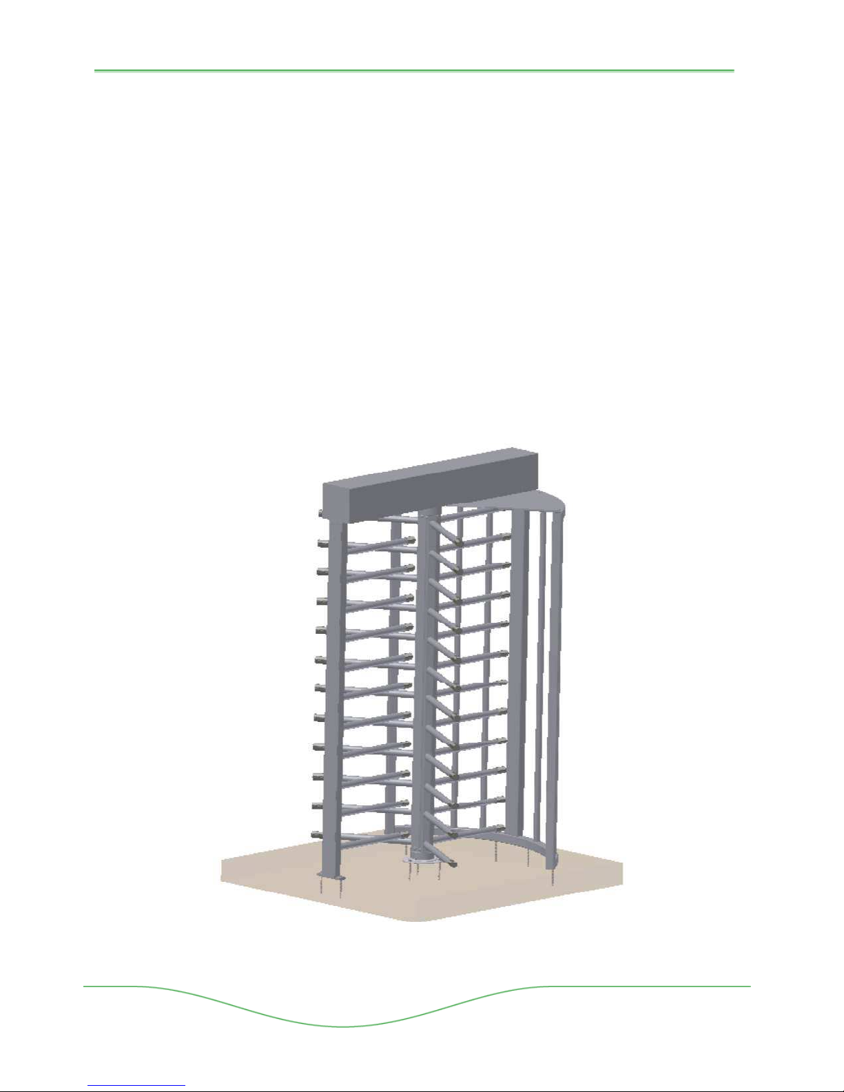
The THT-100 Full Height Turnstile is available in a variety of models and configurations
consisting of a central rotor assembly, Shield Assembly, Barrier and Top Channel Mechanism.
The rotor assembly turns on a central axis preventing passage through the Barrier while
allowing authorized entry/exit through the Shield Assembly passage of the turnstile. Size of the
turnstile can vary but is typically small enough to discourage two persons passing the THT-100.
The typical sizes of a 25” (50cm) width rotor arm, result in a capacity of 25 to 30 persons per
minute in one direction, depending on the authorization system chosen.
A variety of surface finishes are available in galvanized, powder coat and stainless steel,
aluminium anodized and even a combination of metals such as aluminium and stainless steel
together.
All described components are provided in the THT-100 unless otherwise noted with an asterisk
(*) as optional equipment or versions. The THT-100 is a manually operated product,
actuated/controlled by an integrated Main Control Board (MCB) located in the Top Channel
Assembly Mechanism.
Boon Edam Inc.
402 McKinney Parkway Version: Rev A6 10/28//2011
Tel. 910-814-3800 fax 910-814-3899 Issue: THT-100-IMM-USA
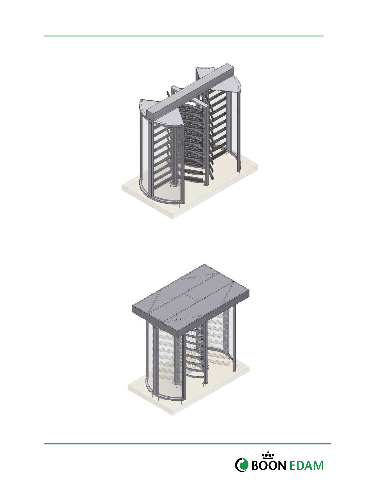
Figure 3-1: THT-100
Page 8
7
Shield
Installation and Maintenance Manual
3.2 Shield Options
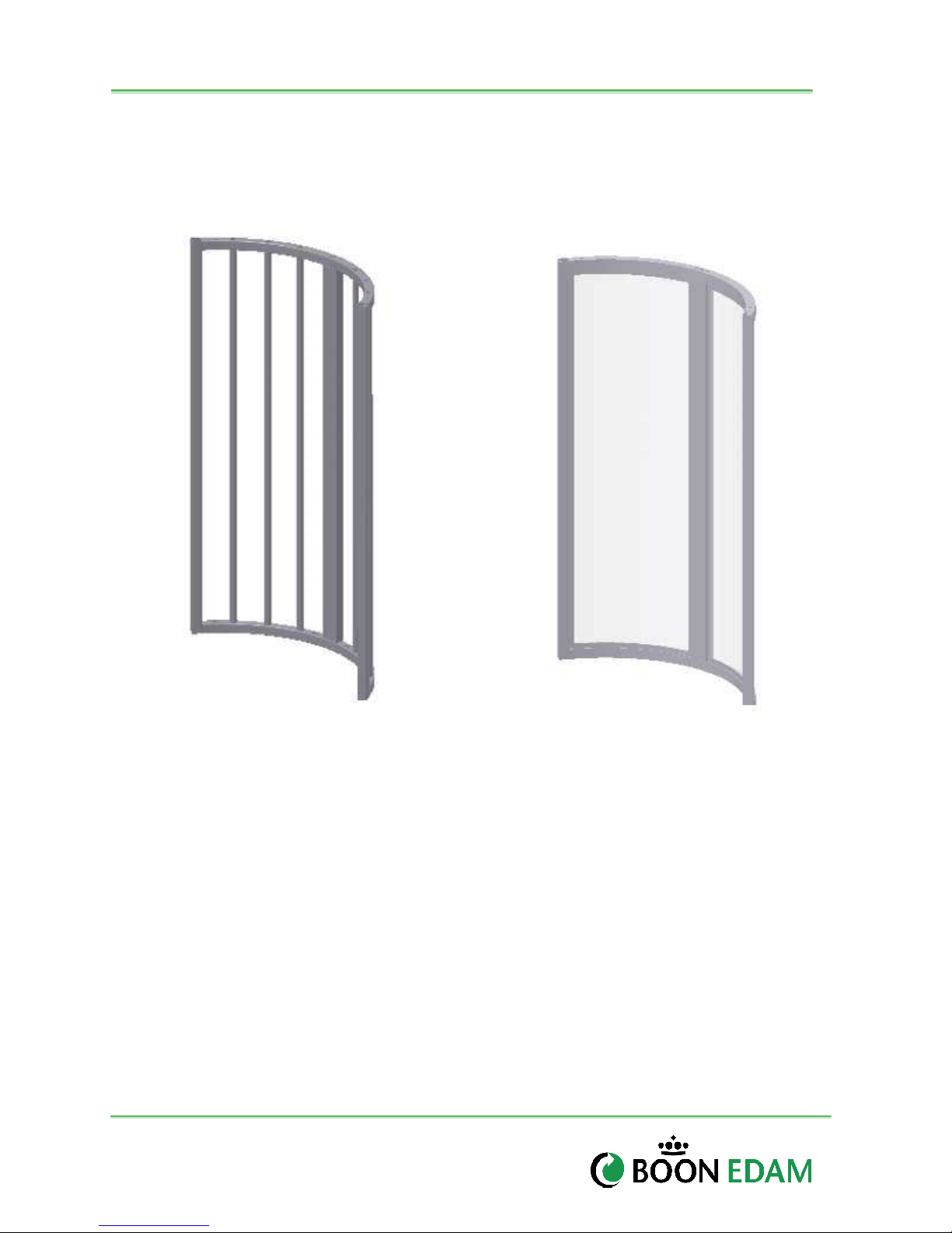
The THT 100 can be configured in a variety of Shield Assembly options. The following shield
options are commonly available.
A - Standard
Figure 3-2: (A) StandardShield and (B) Optional Shield with Lexan Pannels
Version : 10//28/2011
Issue : THT-100-IMM-USA REV A6
B - Shield w/Lexan Pannels
Page 9
THT-100
Standard
Ceiling Plate
8
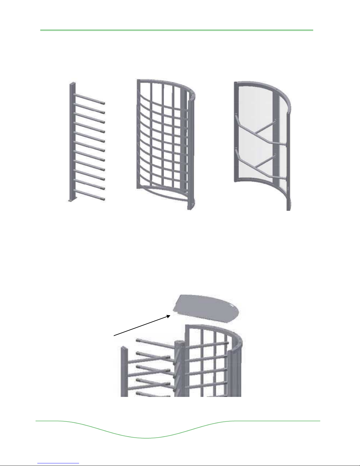
3.3 Barrier Assembly Options
The THT 100 can be configured with a variety of Barrier Assembly options. The following
Barriers are commonly available. Barrier Bars may vary in finish and material depending upon
order.
A -
B – Horizontal Strips
C – Bars W/Lexan Pannels
Figure 3-3. (A) Standard Barrier, (B) Optional Barrier with Horizontal Strips and
(C) Optional Barrier Lexan Panels with Barrier Bars
3.4 Ceiling Plate
The Ceiling Plate consists of a flat angled sheet material (in matching finish) which is fixed
between the Top Channel Assembly and the Barrier.
Boon Edam Inc.
402 McKinney Parkway Version: Rev A6 10/28//2011
Tel. 910-814-3800 fax 910-814-3899 Issue: THT-100-IMM-USA
Figure 3-4. Ceiling Plate Exploded View
Page 10
9
Installation and Maintenance Manual
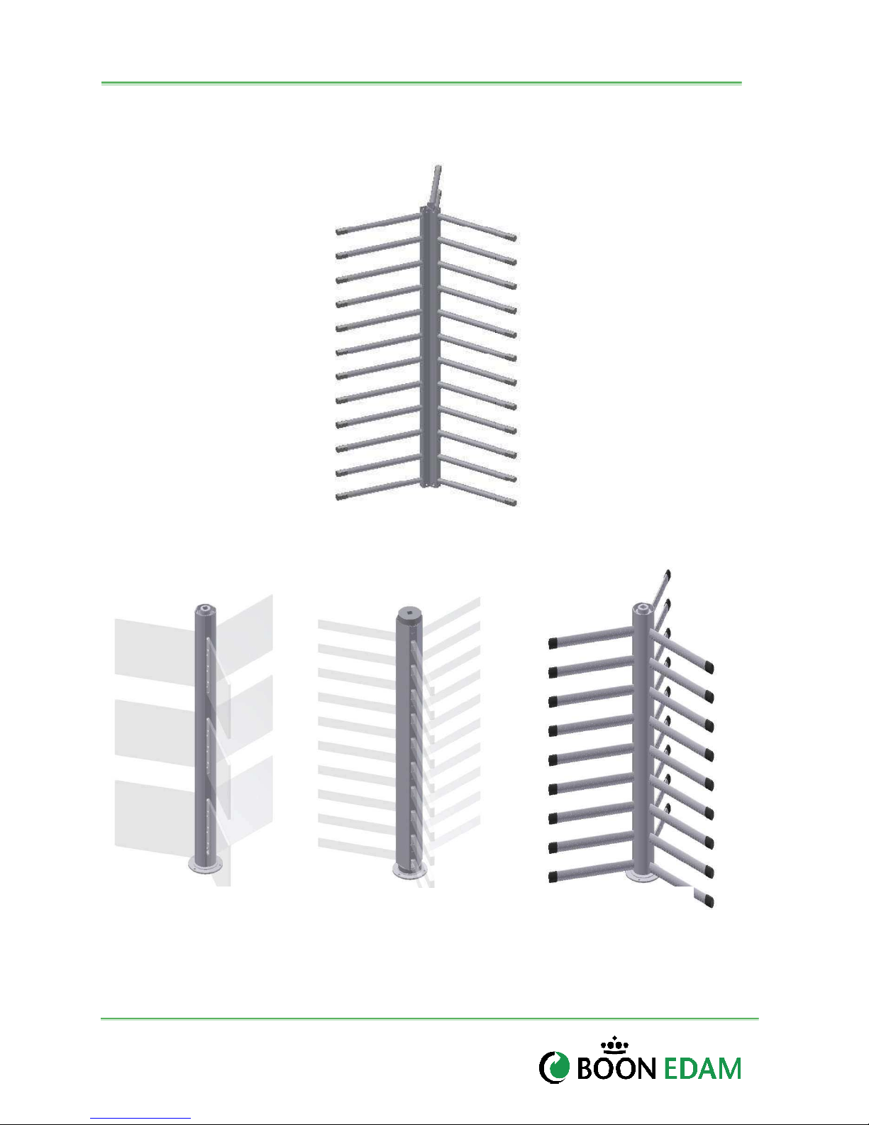
3.5 Rotor Arm Options
The THT 100 can be configured with a variety of Rotor Arm assembly options. The following
Rotors are commonly available.
Figure 3-5. Standard Rotor Arms, (Powder Coat, Stainless or Galvanized)
Other possible Options include:
A - CSTG
Figure 3-6. Optional Rotor Arms, (CSTG and EL and ASTG)
B - EL
C - ASTG
Version : 10//28/2011
Issue : THT-100-IMM-USA REV A6
Page 11
THT-100
10
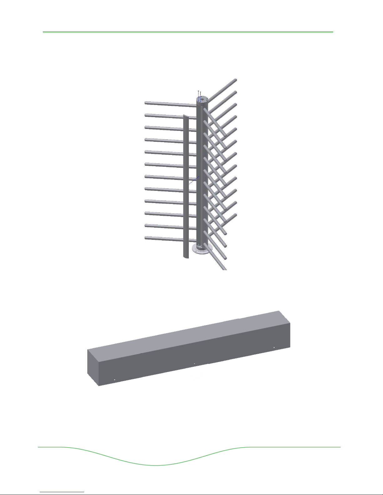
3.6 Rotor Infill Covers (Option)
Optional infill cover pieces can be ordered which cover the center flange bolt assembly area on
the Standard THT-100 rotor arms (note similar snap-in covers are standard on the CSTG, EL
and ASTG models).
Figure 3-7. Infill Cover (Option)
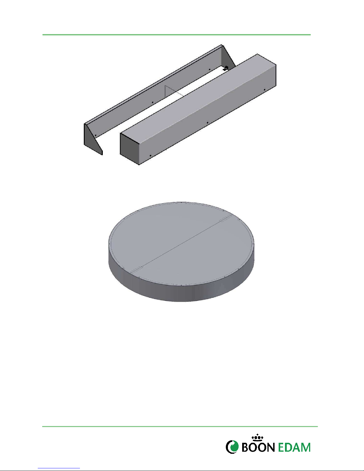
3.7 Top Chanel Cover Options
Figure 3-8. Standard Lift Off Cover (Standard)
Other possible top channel cover options include:
Boon Edam Inc.
402 McKinney Parkway Version: Rev A6 10/28//2011
Tel. 910-814-3800 fax 910-814-3899 Issue: THT-100-IMM-USA
Page 12
11
Installation and Maintenance Manual
Figure 3-9. Two Piece Cover (Option)
Figure 3-10. Round Canopy Cover (EL Option)
Not pictured top channel cover options.
• Hinged Cover
• Panel Cover
• Square Canopy
Version : 10//28/2011
Issue : THT-100-IMM-USA REV A6
Page 13
THT-100
12
3.8 Control System
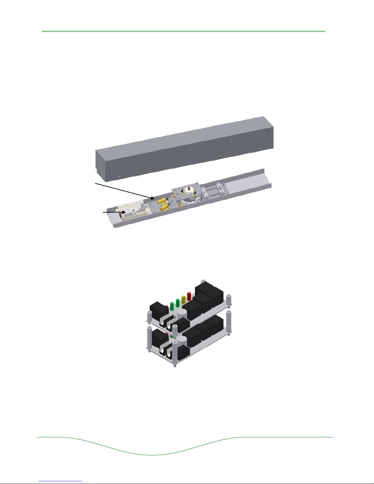
The THT-100 Control Box is located in the upper Top Channel Assembly. Typical mains power
supplied to the control system is 110-230VAC (refer to project specific drawings and
specifications). Within the Control Box, the Main Control Board (MCB) is powered by a 24VAC
power supply system which actuates the locking solenoids which in turn allow the turnstile to
lock and unlock.
A one-way controlled THT-100 incorporates one MCB and related components (for the direction
of access control), and a two-way controlled THT-100 utilizes two MCB’s and related
components (one set for each direction of access control).
Locking
Solenoids
Control Box
with MCB(s)
Figure 3-11: Top Channel Assembly
The MCB(s) and Solenoids are located within the control box and typically are stacked on top of
each other as shown in Figure 3.8.
Figure 3-12: MCB Stack Assembly
Boon Edam Inc.
402 McKinney Parkway Version: Rev A6 10/28//2011
Tel. 910-814-3800 fax 910-814-3899 Issue: THT-100-IMM-USA
Page 14
13
Installation and Maintenance Manual
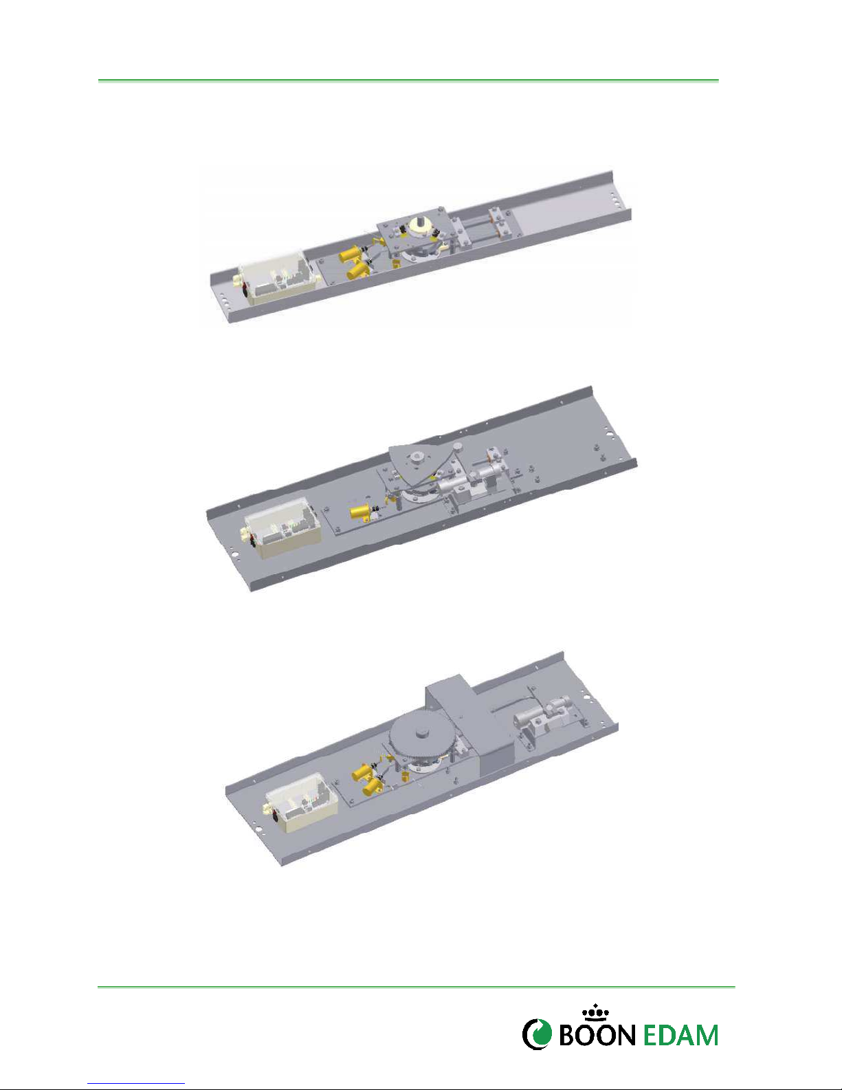
3.9 Speed Control unit
There are three possible options for speed control system of the THT100. Refer to the model
supplied and verify the type of speed control used:
Figure 3-13: Top Channel No Speed Control – Standard
Figure 3-14: Top Channel Triangle Speed Control (Option)
Figure 3-15: Top Channel Gear Speed Control (Option)
Version : 10//28/2011
Issue : THT-100-IMM-USA REV A6
Page 15

THT-100
14
4 Operating concept
4.1 Operating functions
There are many available operating functions of the THT-100 below is a list of typical
configuations. Keep in mind that only one configuration is possible per assembly and is
determined when the unit is manufactured. Changing the configuration of the unit can require
major mechanical changes. Refer to your order or have an authorized Boon Edam Inc. Service
provider inspect your THT-100 if you should have questions regarding the configuration.
Fail Lock - When power is turned off (denied), this configuration provides Fail Lock in
the specified direction. No rotation is allowed in the specified direction. All Fail Lock
units come equipped with a mechanical key override to override the locking system to
allow for free spinning of the rotary arms.
Key Override (Mechanical) - This key switch is typically found on any Fail Lock
direction unit on the underside of the top channel near the upper flange assembly.
When switched to override mode, Fail Lock function can be bypassed for free egress in
the selected direction. Note: FL/FL units will have two key overrides.
When power is restored to the unit, the system will automatically restore to its normal operating
function.
Fail Safe - When power is turned off (denied), this configuration provides Fail Safe
rotation in the specified direction of travel.
Note: Any combination of the above mentioned functions is available in the following
configurations:
• Access Control Rotation (i.e., Card read activation)
• Free Rotation
• No Rotation
Direction types (Clockwise, Counter Clockwise)
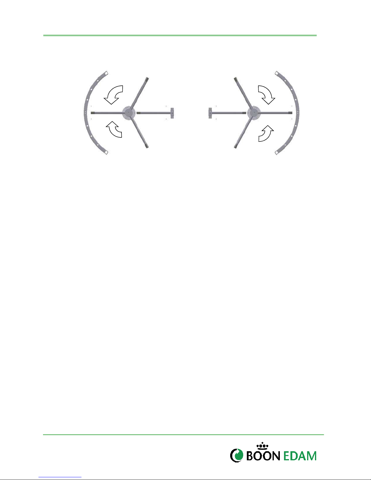
The typical THT-100 rotates in a Counter Clockwise (entry from non-secure moving into the
secure) direction. When authorization is granted, the unit can be manually rotated for one
segment (120 degrees) and return to the rest position and lock. Likewise, for exiting from the
secure to the non-secure side, the unit rotates in a Clockwise direction. Note: Some units may
be ordered with Clockwise entry and Counter Clockwise exit. Always refer to your order
for proper rotating direction.
• Controlled access CCW and CW direction: Both rotating directions require authorization.
The rotating section of the unit will become unlocked for the desired direction upon Access
Control System (ACS) signalling to the THT-100 control system that access has been
granted.
• Controlled access in one direction and free access in the opposite direction: Only
one direction requires authorization. The other direction does not require authorization and
rotates freely when pushed.
• Controlled or Free access in on direction and No Access in the opposite direction:
Access is only allowed in one direction (via access control or free access in). The opposite
direction does not allow traffic to pass.
• Free Access in both directions: There is no access control connected to this type of unit
and it will freely spin in either direction.
Boon Edam Inc.
402 McKinney Parkway Version: Rev A6 10/28//2011
Tel. 910-814-3800 fax 910-814-3899 Issue: THT-100-IMM-USA
Page 16
15
Rotation
Installation and Maintenance Manual
Counter Clockwise
Secure Side
Clockwise Rotation
Clockwise Rotation
Non- Secure Side
Counter Clockwise
Rotation
Figure 4-1: THT-100 Plan View Examples
Layout and Rotation Directions
4.2 Access control system (ACS)
The THT-100 is designed to integrate with most access control systems by means of an
authorization signal. When the THT-100 receives the signal from ACS, the internal control system
releases the locking solenoid in the desired rotating direction.
4.3 Security
Several Security features are designed into the THT-100 unit. The following devices are typical
features found in most units.
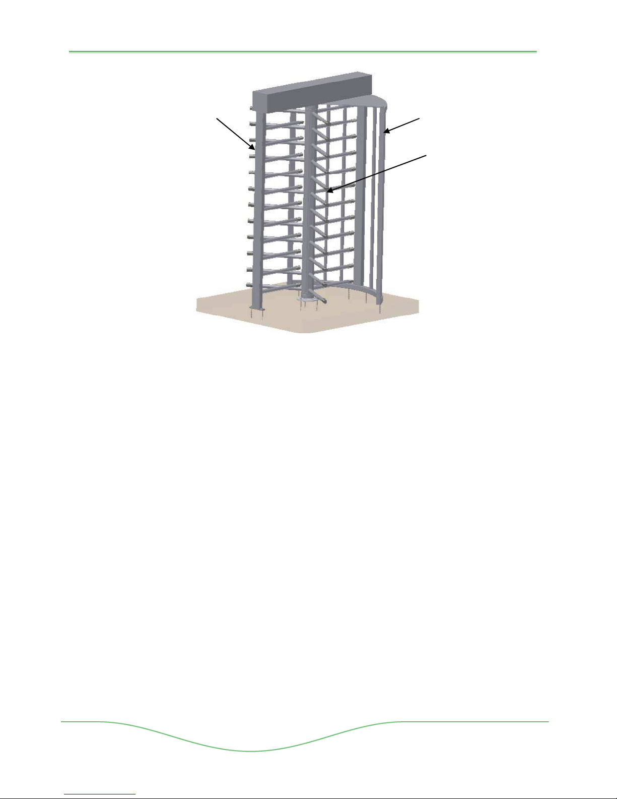
• Restposition: When the rotor arms are in their respective locked rest position, they will be
held tight by the force of locking pawls and ratchet assembly. This will prevent movement of
the rotor arms by hand when the unit is in its locked home position
• Barrier Unit: Prevents unauthorized entrance by individuals trying to tailgate in the opposite
direction of a passage by an authorized user.
• Shield Assembly: Creates a secure compartment area where the rotor arms travel and
authorized users pass.
Version : 10//28/2011
Issue : THT-100-IMM-USA REV A6
Page 17
THT-100
16
Shield
Barrier Unit
Assembly
Rotor Arm
Assembly
Figure 4-2: THT-100 in typical Rest Position.
4.4 Optional and Configuration Features
Items indicated by an asterisk(*) are noted as optional.
Rotation Detection Switch*
The optional rotational detection switch is located within the Top Channel Assembly. When an
authorized user rotates the unit, this detection switch sends a dry contact closure back to the
ACS to notify that the unit has been turned. The unit will then reset and wait for additional
authorizations.
Home Position Switch *
When the THT 100 reaches its resting position, this is called the home position. A small microswitch is activated notifying the control system that the unit is in its home position.
Solenoid activation switch*
When a solenoid is activated a small micro-switch is activated notifying access control that the
rotor arms are unlocked.
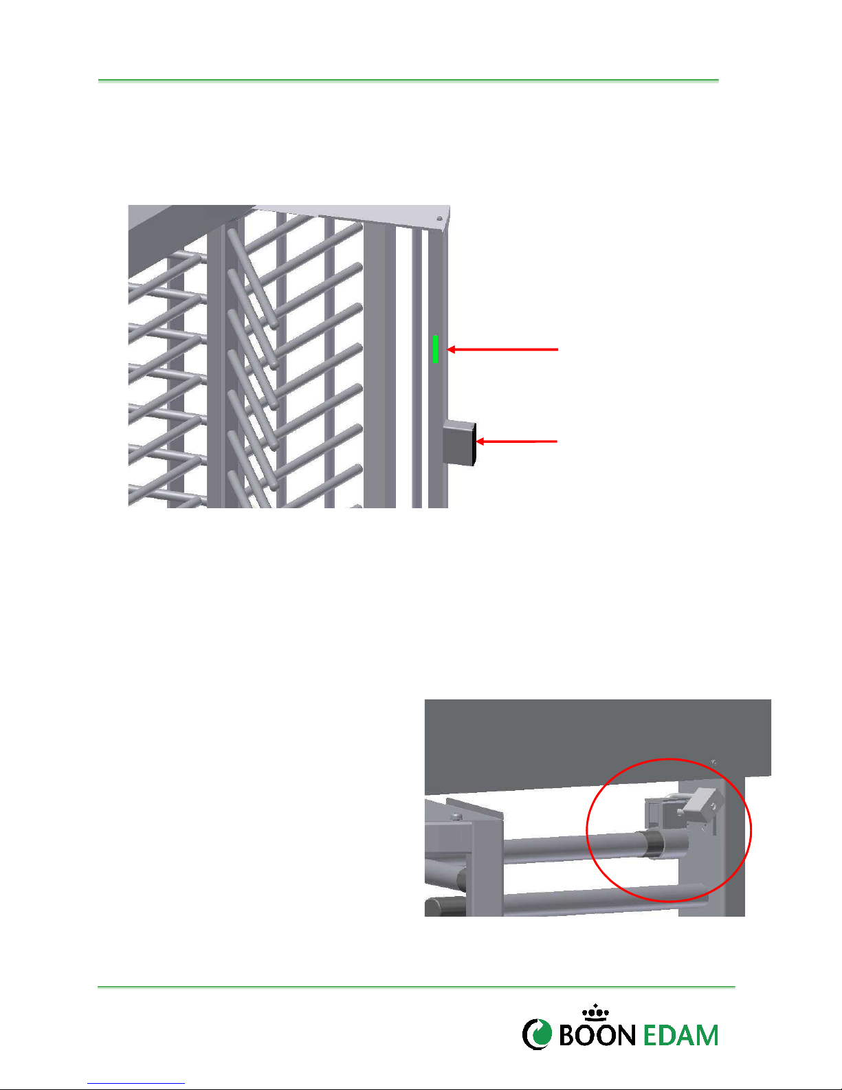
Traffic Lights*
Optional traffic lights can be installed in the end posts of the shield surrounding the walk path.
The LED’s illuminate Red when the unit is locked and in stand-by waiting for an authorization.
When a valid card read signal is sent from the Access Control System to the THT-100, the LED’s
on the respective side will turn Green. Once a user passes through the unit, the LED’s will turn
back to Red.
Boon Edam Inc.
402 McKinney Parkway Version: Rev A6 10/28//2011
Tel. 910-814-3800 fax 910-814-3899 Issue: THT-100-IMM-USA
Page 18
17
Installation and Maintenance Manual
Card Reader Mounting Box*
Optional Card reader mounting boxes can be provided which mount to the outer vertical post.
The size of this box houses most card readers and provides adequate space for wire routing of
access control systems.
Traffic Light Traffic Light
Card Reader
Mounting Box
Figure 4-3. Card Reader Box and Traffic Light (Options)
Speed Control Dampening System*
THT-100 units are equipped with Optional Speed Control Dampening System to reduce the
amount of bounce which the rotor arms can experience after a full rotation when pushed hard.
The Speed Control will apply force against the rotating direction to slow the unit down for a
gradual rest position (see Section 3.6 Speed Control Unit).
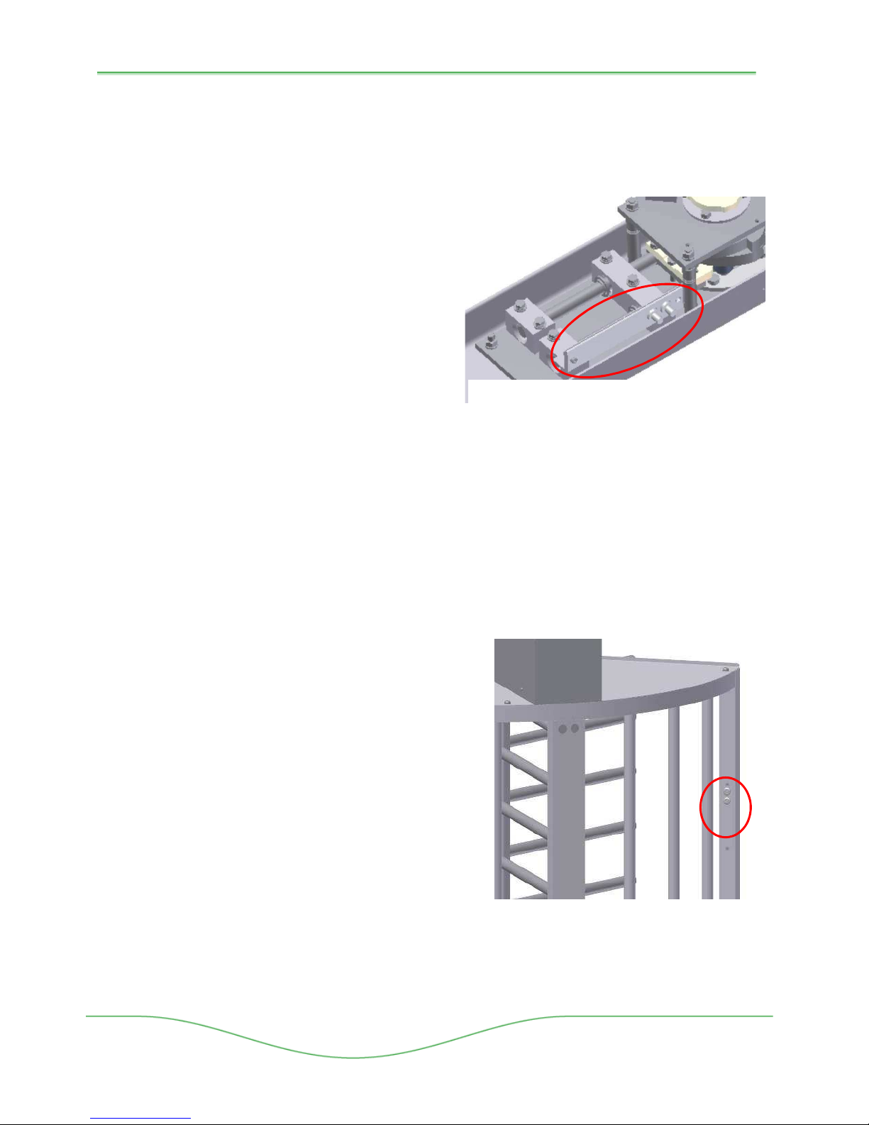
Out of Use Lock *
An optional mechanical lock can be ordered
with most THT-100 units. The lock
mechanism is connected to the Barrier
assembly and connects/locks to the Rotor Arm
preventing the unit from turning. A standard
pad lock can be used to secure the
mechanism (supplied by others).
Figure 4-4. Out of Use Lock (option)
Version : 10//28/2011
Issue : THT-100-IMM-USA REV A6
Page 19
THT-100
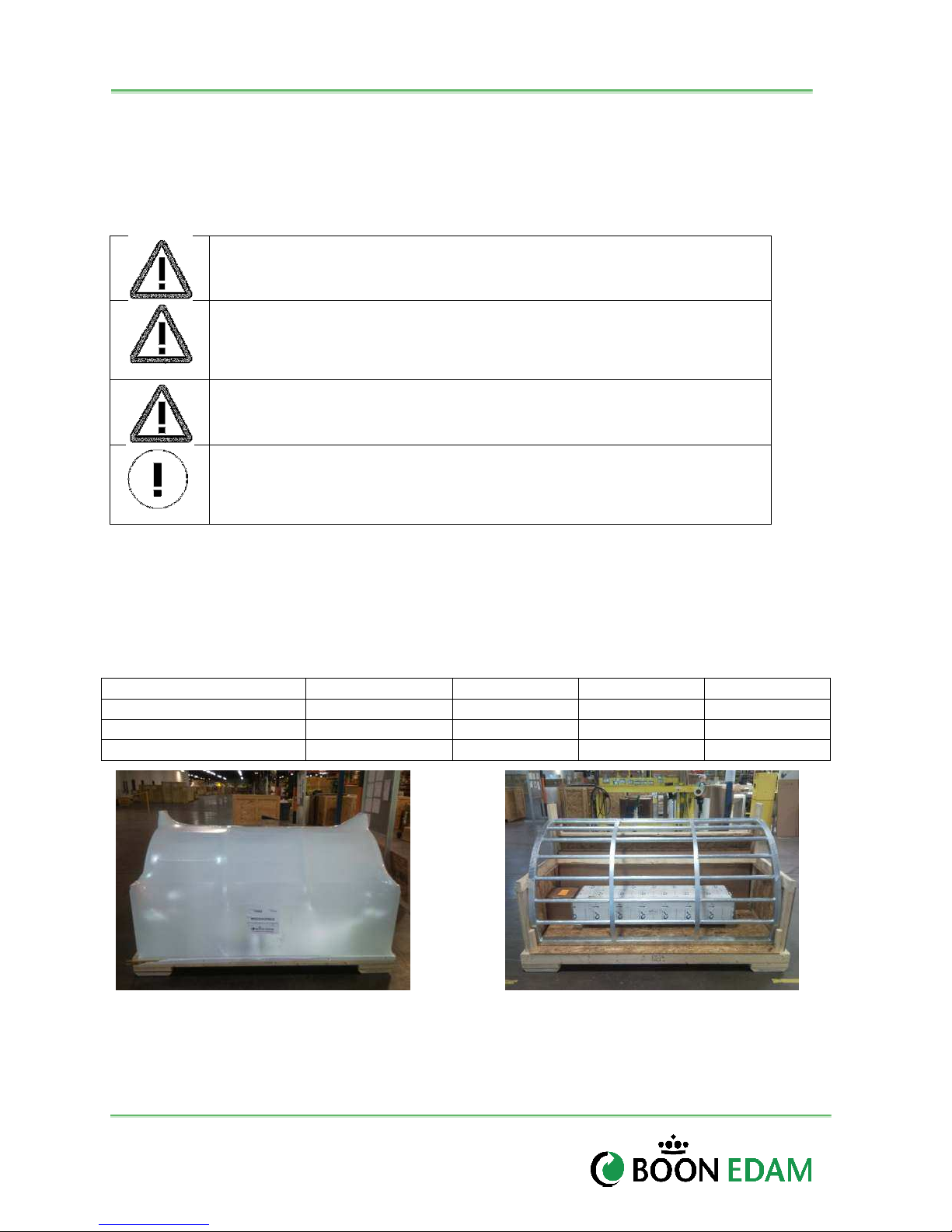
Figure
4-6. Electric Override Key Switches
Figure
4-5. Heating Element Strip
18
Heel guards*
The bottom rotor arms of the THT-100 can be fitted with an optional heel guard protector to
reduce direct contact of heels with the rotor arms. If a unit is pushed against a person’s foot or
heel the foam rubber protector will reduce the impact.
Heating Element Strips*
Optional heating element strips can be ordered
and applied to the internal top channel mechanism
for cold climate use. Power requirements (110220 VAC) vary depending upon the model ordered
and are to be connected separately from the main
control system, by others.
Fire alarm
For units tied into a fire alarm system, The THT100 can be configured to work accordingly. Keep
in mind that power failure functions override fire
(110-220VAC by others)
alarm functions (reference 4.4.3). The Fire Alarm inputs found inside the Main Control Box are
directional, and dependent upon the configuration of the locking system (e.g., Fail Lock Exit or
Fail Safe Exit). The following configurations are available:
• Fail Lock/Fail Safe – Under Fire, it is free out, no entry
• Fail Safe/Fail Safe – Free Entry and Exit
Fail Lock: Will release when the fire alarm is activated, however, if mains power is lost,
it will only open upon keyswitch bypass.
In case of a fire alarm, the rotor arms will allow free passage through the barrier. The
LED’s will turn green for free egress in the
configured direction. In case of simultaneous
power failure, reference 4.4.3 for Power Failure
functionality.
Electric Override Key Switch(es) (optional)
The secure side of the THT-100 incorporates electric
override keyswitches into the back side of the shield
assembly post. The keyswitches allow the owner to
select functions of Card Read In/Free In or Card
Out/Free Out when the respective key switch is
activated.
Boon Edam Inc.
402 McKinney Parkway Version: Rev A6 10/28//2011
Tel. 910-814-3800 fax 910-814-3899 Issue: THT-100-IMM-USA
Page 20
19
Installation and Maintenance Manual
INSTALLATION
5 Installation procedure
Always verify meet with the owner/owner’s representative to verify the exact location and check
for any unforeseen obstructions prior to installation.
WARNING!
Risk of personal injury or loss of life.
WARNING!
When working internally on the THT-100, always be aware of moving
mechanical components.
WARNING!
Before working on the THT-100 be sure to switch off the power supply.
CAUTION!
The material may be damaged or the operation of the door affected.
5.1 Packaging and Crating
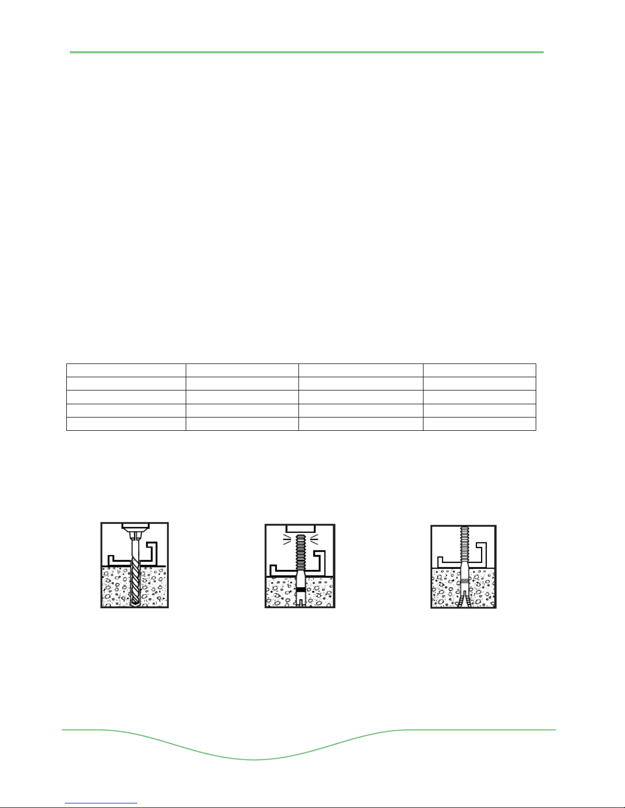
Typical packaging/crating of a THT-100 unit consists of similar packaging pictured below. Note:
Tandem and Special order unit crating systems may vary. Verify with Boon Edam for exact
crate dimensions and weights. The use of a lift is recommended when receiving and offloading
the THT-100 unit.
Product Type Crate Length Crate Width Crate Height Total Weight
THT-100 EC2, ES, EA 87” (2201mm) 44” 48” 716lbs
THT-100 TC2 (Tandem) 103” (2602mm) 54” 46” 1600lbs
Figure 5-1. THT-100 Typical Packaging (wrapped and unwrapped)
Version : 10//28/2011
Issue : THT-100-IMM-USA REV A6
Page 21
THT-100
Bo
lt Size
Thread Size
Torque Value ft lbs
Torque value nm
20
5.2 Tool and Manpower List
Typical THT-100 installations require two men for standing and lifting materials into place. The
following tools are needed for installation.
• Metric End wrench set
• Basic Metric Socket Set
• Metric Allen Wrench Set
• Precision Flat Blade Screw Driver, 1.5-4mm
• Hammer Drill with rotary hammer drill bits (3/8” for concrete anchoring)
• 4’ Level
• 6’ Ladder
• Tape Measure
• Electrical Fish Tape (for pulling ACS and power control wires)
• Electrical Wire Stripping and Cutting Pliers.
• 4” to 6” Nylon Cable Ties
5.3 Bolt Torque Specifications
Use the following torque values for bolt connections, unless stated differently in the installation
manual or mechanical drawings.
M5 0.8 4.13 5.6
M6 1.0 7.1 9.6
M10 1.5 34 46.09
3/8 16 40 54.23
5.4 Anchor Techniques
Boon Edam recommends using 3/8” minimum anchor bolts supplied with the hardware kit.
1. Drill hole
same
diameter as
anchor to
be
embedment
2. Drive Anchor
with expander
plug in bottom
through material
to be fastened
3. Expand
anchor by
driving
anchor over
plug with
hammer.
Boon Edam Inc.
402 McKinney Parkway Version: Rev A6 10/28//2011
Tel. 910-814-3800 fax 910-814-3899 Issue: THT-100-IMM-USA
Page 22
21
Installation and Maintenance Manual
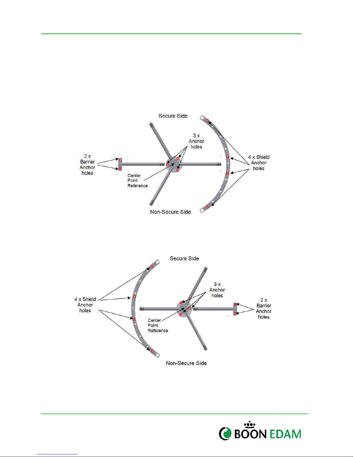
5.5 Anchor Locations
The THT-100 unit is secured to the floor at several locations (Note: the Non-secure and Secure
side of the turnstile, Counter-Clockwise and Clockwise rotating directions). It is important to
layout the unit as illustrated in Figure 5.2 for proper operation. This manual lays out the unit in a
Counter Clockwise Rotation. To install in a clockwise rotation, simply reverse the anchoring
layout as shown below. Anchor hardware is supplied with the installation kit containing the
quantity of nuts and bolts necessary to install the unit. .
Counter Clockwise Entry Installation
Clockwise Entry Installation
Figure 5-2: Typical Anchor locations and Center Point (THT-100EC)
Version : 10//28/2011
Issue : THT-100-IMM-USA REV A6
Page 23
THT-100
22
5.6 Floor layout
Typical Layout*
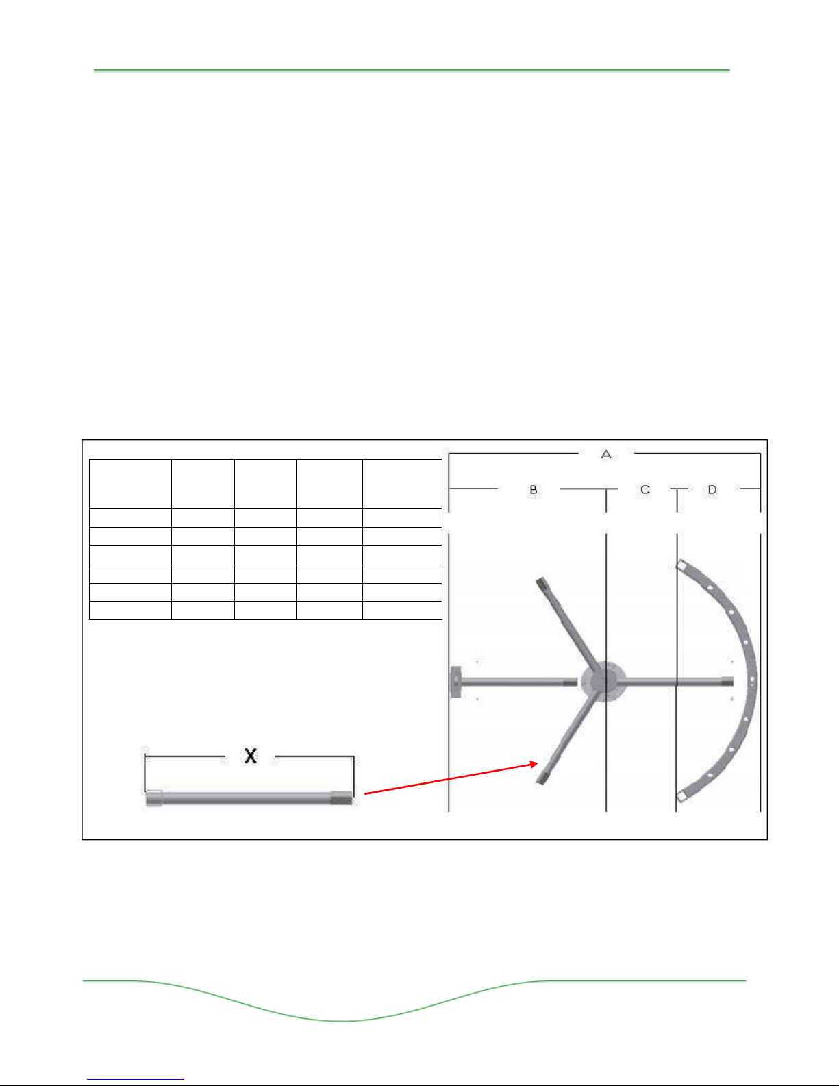
Each THT-100 product will be delivered with a two page set of drawings showing the actual
dimensions necessary for layout of the unit. The center point of the unit is the best reference for
laying out the unit. Additional floor mounting templates are available upon request.
Page 2 of the product drawings will provide the dimensions of the inside radius which the Shield
and Barrier Assemblies line up with. Verify how level the ground is that the THT-100 will be
installed on. The more level the ground is, the better the installation will be. Verify this with a
level for accuracy. The surface should be within 1/4” (6mm) level across the finished surface.
1. Mark a straight Center Line across the entire width of the opening where the THT-100
will be installed.
2. Find the Center Point of the opening. This is where the Base Plate (pivot point) will be
mounted.
3. Using dimension in Table 5.2, determine the Center Point and layout the dimensional
lines where the Barrier and Shield will mount.
X
(Rotor Arm)
22 ¾” 52” 26” 9 ¾” 16 ¼”
24 ¾”” 60” 30” 13 ¾” 16 ¼””
27 ¾” 66” 33” 15 5/8” 17 3/8”
30 ¾” 72” 36” 16 ¼” 19 ¾”
38 ¾” 88” 44” 18 ¾” 25 ¼”
48” 106” 52” 23” 29”
A
(Opening)
B
(Center)
C
(Arc)
D
(Shield)
Notes:
Dimension “A” is Outside post to post dimension.
Dimension X of the Rotor Arm is from end to end
of the rotor arm including the square post.
Figure 5-3: Dimension Table
* Typical Layout is for a Counter Clockwise rotation. For Clockwise rotating units, the
dimensions shown in Figure 5.3 Dimension Table should be mirrored.
Boon Edam Inc.
402 McKinney Parkway Version: Rev A6 10/28//2011
Tel. 910-814-3800 fax 910-814-3899 Issue: THT-100-IMM-USA
Page 24
23
Installation and Maintenance Manual
5.7 Mechanical Assembly
Base Plate
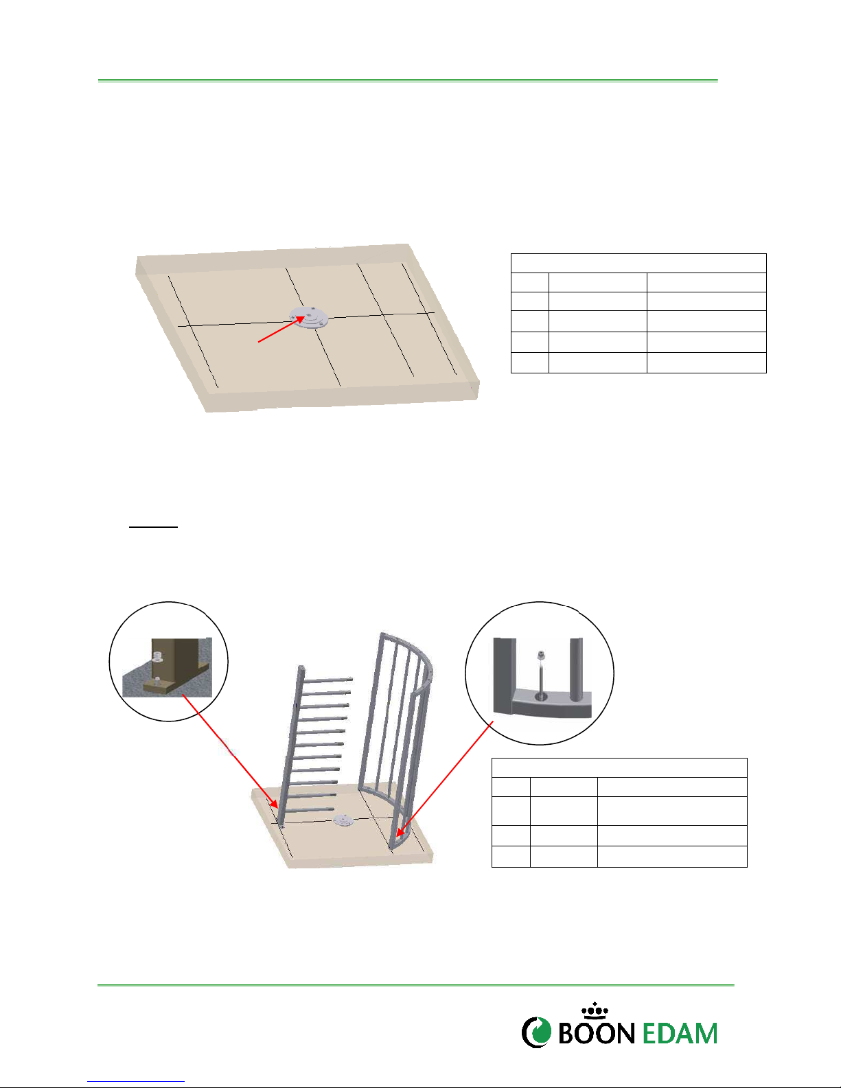
Center the Base Plate over the Center Point Mark as shown in Figure 4.3. Mark through the
Base Plate holes to the flooring. Using a hammer drill and 3/8” bit, drill holes for anchor bolts
into flooring surface.
Secure
Center
Point
Parts Used in this Process
Qty Part # Description
1 100-039E Base Plate
3 HW055 3/8” Anchor Bolts
3 HW056 3/8” Flat Washer
3 HW057 3/8” Nuts
Non-Secure
Figure 5-4: Bearing Plate
Shield and Barrier Assemblies
The outside edge of the shield and outside edge of the barrier assemblies layout on the floor
markings with the appropriate lines as designated in Figure 5.2. Using a hammer drill, drill and
anchor the 3/8” bolts at the six mounting hole locations as illustrated in Figure 5.1. Stand the
barrier and shield and tighten in place as shown in Figure 5.4 using the 3/8” nuts and Flat
washers.
2x
Anchor
4x
Anchor
Secure
Hardware Used in this Process
Qty Part # Description
6 HW055
6 HW056 3/8” Flat Washer
6 HW057 3/8” Nuts
Non-Secure
3/8” Red Head Anchor
Bolts
Figure 5-5: Shield and Barrier Anchoring
Version : 10//28/2011
Issue : THT-100-IMM-USA REV A6
Page 25
THT-100
24
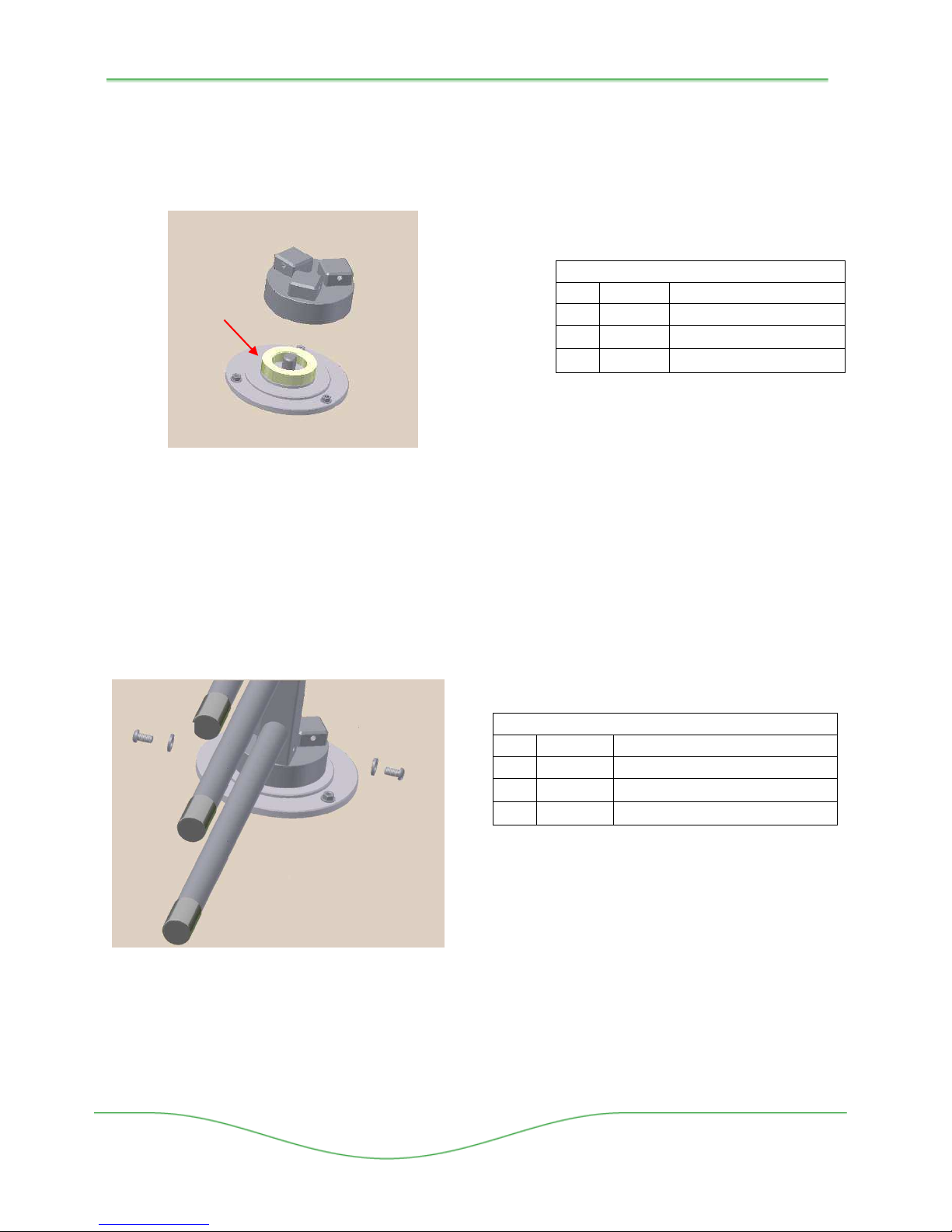
Bottom Bearing and Flange Housing
Place the bottom bearing on top of the anchored base plate. Make certain a generous coat of
Grease has been applied to the bearing. Cover with the bottom flange.
Hardware Used in this Process
Apply
Grease
Figure 5-6: Bottom Base Plate, Bearing and Flange
Qty Part # Description
1 100040 Bottom Bearing
1 Various Bottom Flange Housing
1 Lithium Grease
Rotor Arm Assembly
Bottom Rotor Assembly - Place a rotor arm assembly into the bottom flange pin block. Tighten
with two M10 bolts and spring lock washer. A second person will be needed to hold the rotor
arm in place. Repeat the process until all three rotor arms are bolted to the bottom flange
housing (see 5.10 for ASTG, CSTG and EL rotor arm assembly).
Hardware Used in this Process
Qty Part # Description
3 Various Rotor Arm Assembly
6 HW038 M10 x 1.5 x 20 socket head
6 HW003 M10 Spring Lock Washer
Figure 5-7: Bottom Rotor Arm Assembly
Boon Edam Inc.
402 McKinney Parkway Version: Rev A6 10/28//2011
Tel. 910-814-3800 fax 910-814-3899 Issue: THT-100-IMM-USA
Page 26
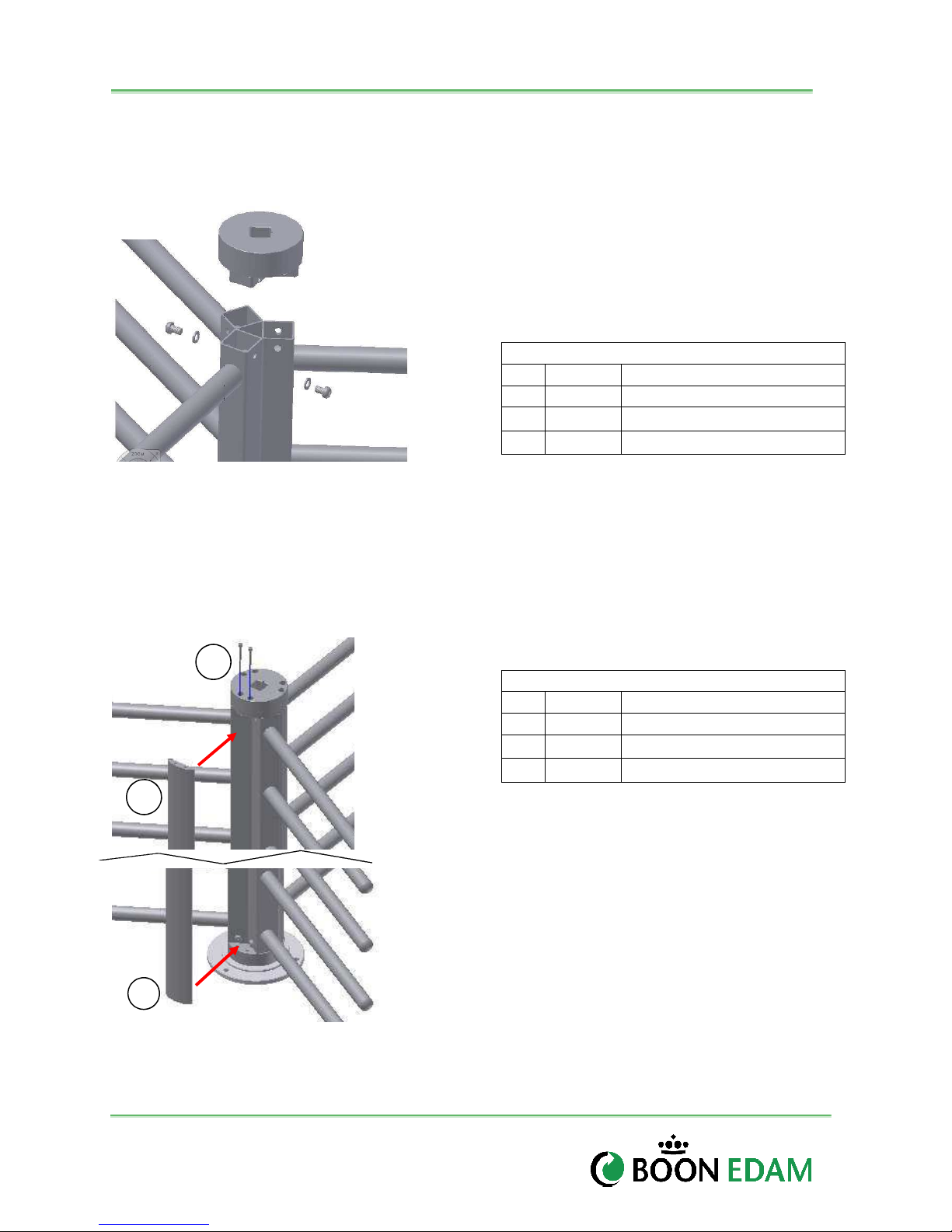
25
Installation and Maintenance Manual
Top Rotor Assembly
Place the upper flange blocks inside of the top of all three rotor arm posts and tighten down
using M10 bolts and spring lock washers. Note: if optional infill pieces are supplied. They
must be inserted before the top channel is installed. See figure 5.8 for illustration.
Hardware Used in this Process
Qty Part # Description
1 Varies Upper Flange
6 HW038 M10 x 1.5 x 20 socket head
Figure 5-8: Top Rotor Arm Assembly
Optional Rotor Infill Pieces (Powder Coat, Galvanized and Stainless models only)
if equipped with optional rotor infill pieces, the bottom of the infill piece will include pins which
mount into the bottom flange first. Once the pins are inserted, move the top of the infill piece
into position and then insert the pins through the top. Note: ASTG, CSTG and EL models use
a snap in Infill pieces which do not require the mounting pins (Refer to ASTG/CSTG Installation
Appendix for further information.
6 HW003 M10 Spring Lock Washer
Figure 5-9: Optional Rotor Infill Pieces
Version : 10//28/2011
Issue : THT-100-IMM-USA REV A6
Optional Hardware Used in this Process
Qty Part # Description
3 Varies Infill Pieces
6 M6 x 40 socket head
Page 27
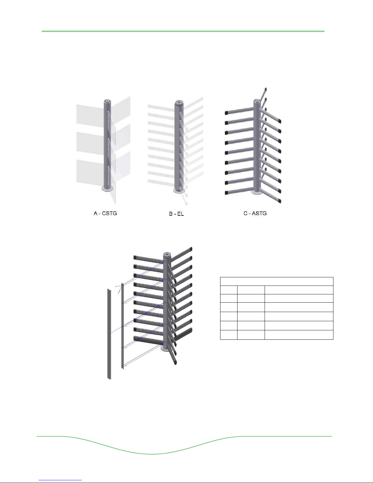
THT-100
Retainer Angle
Snap
-
in Infill
26
ASTG CSTG and EL Rotor Arm Assembly (Option)
The rotor arms of the ASTG, CSTG, and EL units assemble in the same manner as the
standard THT-100 rotor arms and always include a two piece standard snap-in style infill pieces
(see figure 5.11)
Figure 5-10. Optional Rotor Arms, (CSTG and EL and ASTG)
Hardware Used in this Process
Qty Part # Description
3 Varies Snap-in Infill Piece
6 Varies Retainer Angle Piece
15 HW M6 x 70 HHS Bolts
15 HW M6 Nuts
15 HW M6 Flat Washer
Figure 5-11 Rotor Arm Snap-in Infill
After the rotor arms are connected to the Top and Bottom Hub assemblies, connect the retainer
angle to the rotor arms using the m6 x70 HHCS bolts, lock washers and flat washers as shown
in Figure 2-5.
Boon Edam Inc.
402 McKinney Parkway Version: Rev A6 10/28//2011
Tel. 910-814-3800 fax 910-814-3899 Issue: THT-100-IMM-USA
Page 28
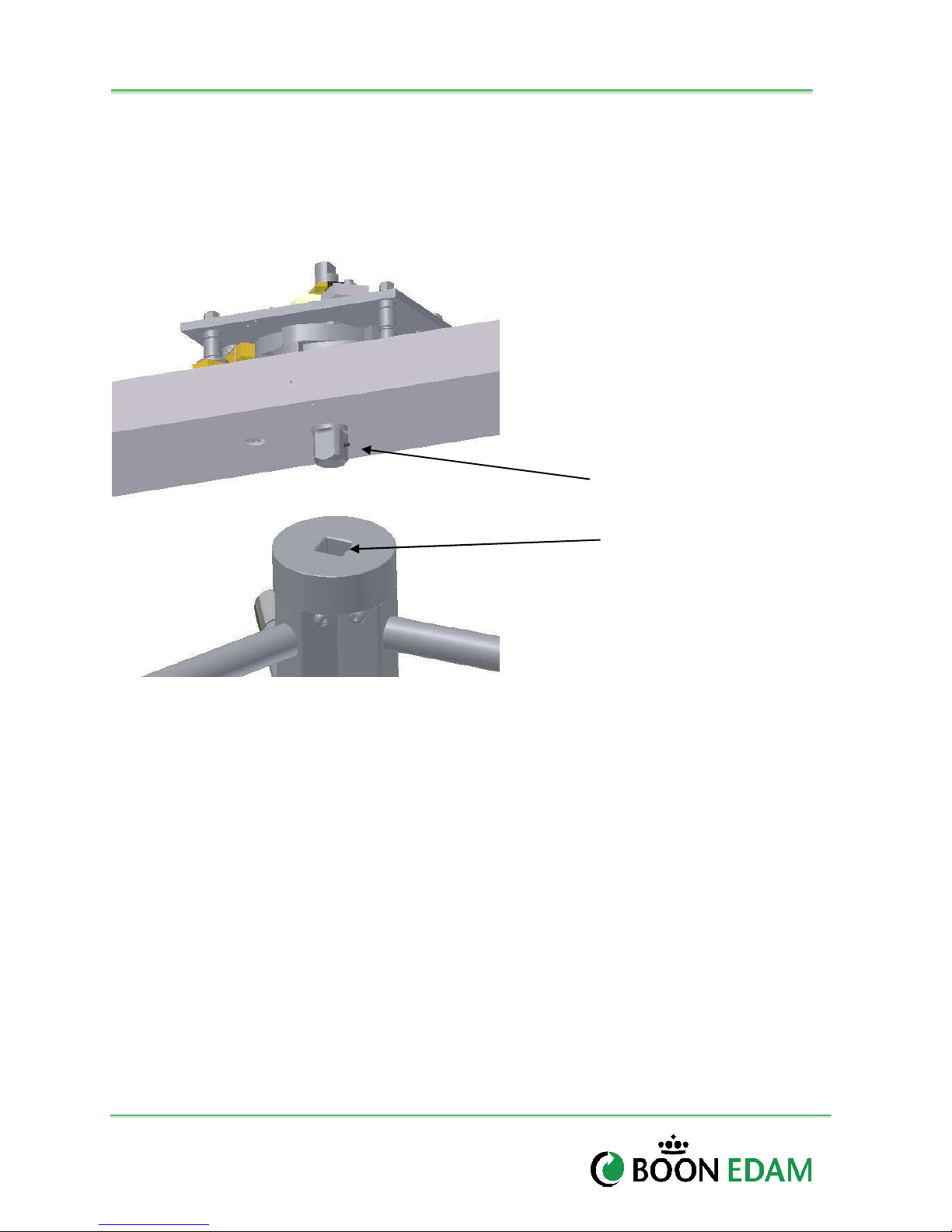
27
Installation and Maintenance Manual
Top Channel Direction Alignment
When setting the top channel on top of the ceiling plate, shield, and barrier post, it is necessary
to verify that the top channel is positioned properly. An alignment roll pin in the top channel
assembly shaft should set into the alignment guide of the top flange assembly. Alignment of
these components will assure the proper resting position of the unit (Reference Figure 5.1 for
proper rest position example).
Alingment Roll Pin
Alignment Guide
Figure 5-12: Top Rotor Arm Assembly
Version : 10//28/2011
Issue : THT-100-IMM-USA REV A6
Page 29
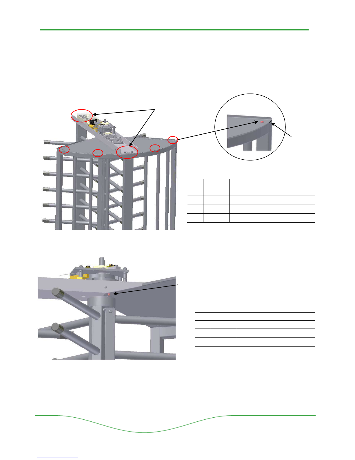
THT-100
28
Ceiling Plate and Top Channel Connection
The ceiling plate mounts to the top of the shield assembly. Gaskets fit between the ceiling plate
and each endpost Four M10 bolts connect the ceiling plate to the shield assembly. Four M10
bolts, lock washers and flat washers connect the top channel to the mid-post of the shield and
barrier post.
4 x M10
Bolt/Flat/Lock
Hardware Used in this Process
Qty Part # Description
6 HW038 M10 x 1.5 x 20 Bolt
6 HW003 M10 Spring Lock Washer
6 HW019 M10 Washer
2 Ceiling Plate Gasket
Two additional M5 bolts, and lock washers
and connect the shield up into to the top
channel.
Hardware Used in this Process
Qty Part # Description
2 HW001 M5 x 8 Socket
2 HW016 M5 Spring Lock Washer
Figure 5-13: Top Channel and Ceiling Plate Bolt Connections
4 x M10
Bolt/Flat/Lock
Gasket
Boon Edam Inc.
402 McKinney Parkway Version: Rev A6 10/28//2011
Tel. 910-814-3800 fax 910-814-3899 Issue: THT-100-IMM-USA
Page 30
29
Installation and Maintenance Manual
Top Channel Cover
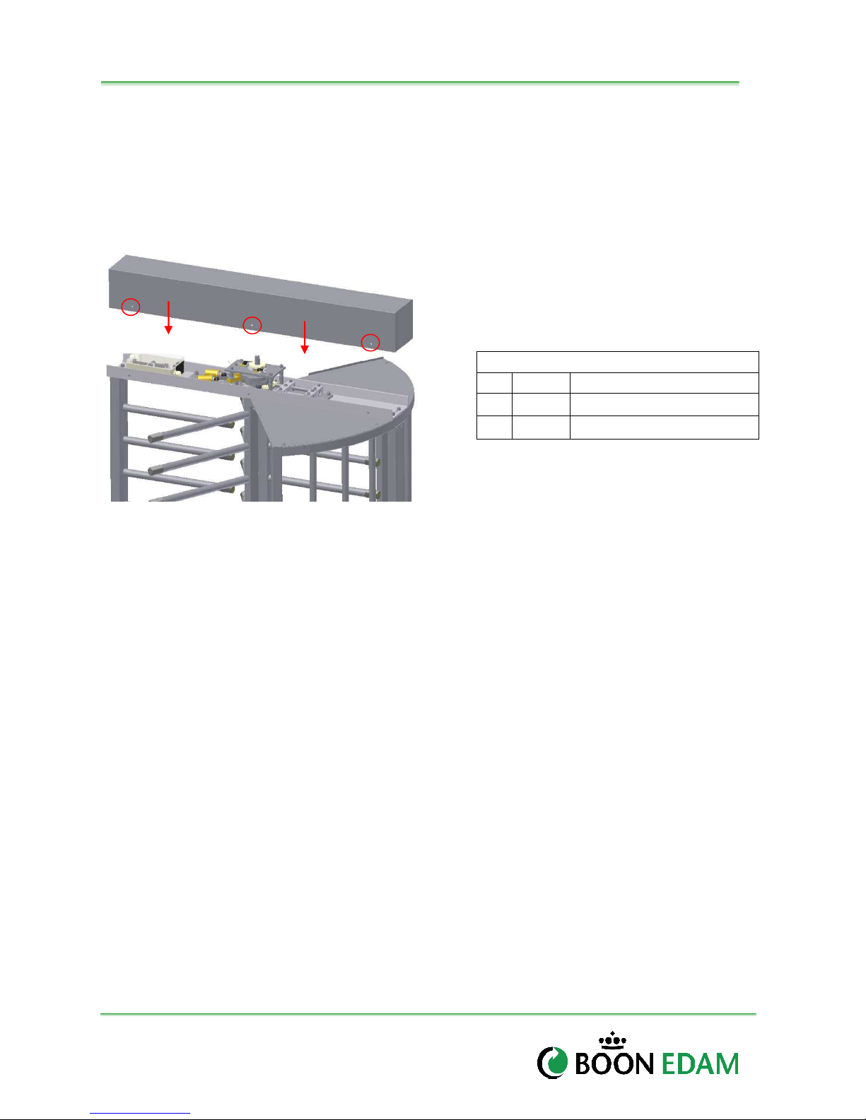
The standard cover fits over the top channel and mechanism. It is connected by six M5 bolts
and flat washers. Note: See section 5.6 before securing the top channel cover. It is
necessary to connect electrical power, access control and check the operation of the
mechanism.
Hardware Used in this Process
Qty Part # Description
6 HW054 M5x0.8 x 13 Bolt
6 HW020 M5 Washer
Figure 5-14: Top Channel and Ceiling Plate Connections
Version : 10//28/2011
Issue : THT-100-IMM-USA REV A6
Page 31
THT-100
30
5.8 Electrical installation
The requirements for the mains power supply are:
• Power supply: 110-240 VAC, 50/60 Hz (Verify correct Voltage with your order)
• Internal Fuse of MCB: 15A
• Recommended Breaker: 20 amp single pole (110VAC), Double pole (<200VAC).
• Refer to the electrical drawings (E-drawings) for more detailed information.
Mains Electrical Connection
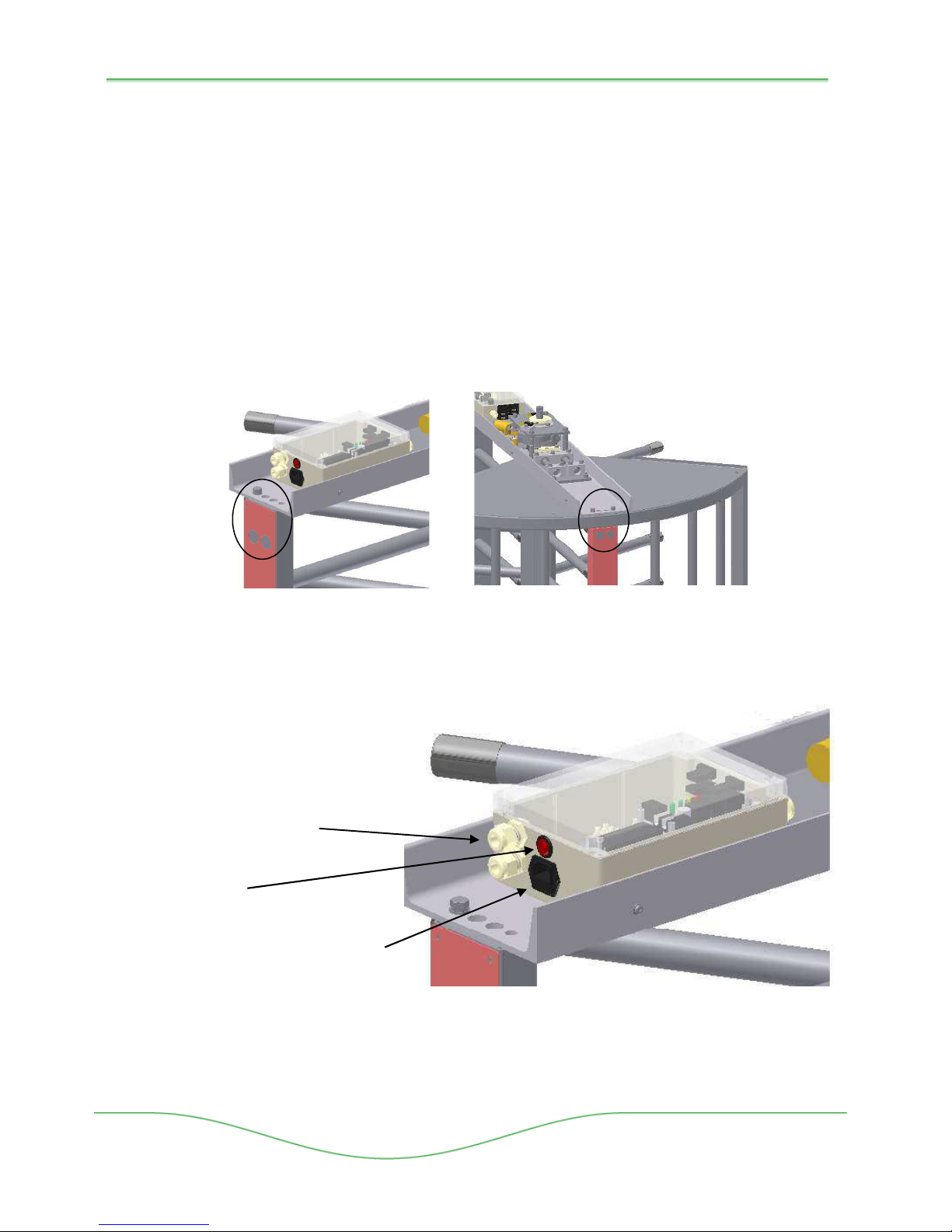
Electrical service conduit holes are designed into both mid-posts of the THT-100. There are two
holes on each side for running mains power, access control, fire alarm or other necessary
communications to the unit. The Endposts and Midpost and Barrier post also function as a
conduit for channeling electrical wires from the ground up into the control box.
A standard electrical cable is supplied with the unit which connects to the control box. Connect
in accordance with local electrical code requirements. The following components are included
for connection of the controls to the building system:
Figure 5-15: Conduit Holes
Wire Strainers for ACS
On/Off Switch
Receptacle for Mains Connection
Boon Edam Inc.
402 McKinney Parkway Version: Rev A6 10/28//2011
Tel. 910-814-3800 fax 910-814-3899 Issue: THT-100-IMM-USA
Figure 5-16: Main Control Box
Page 32
31
Connection Point
Cable Part
Descriptio
n Main Control
Device End
Installation and Maintenance Manual
5.9 Main Control Box
Cable Connections
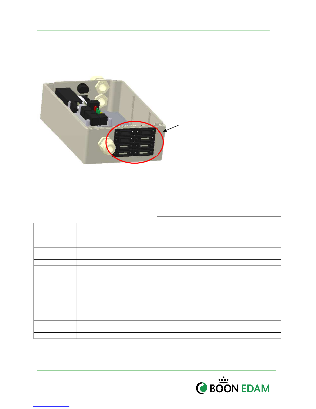
There are many cables which connect to the Main Control Box. The following cable plugs are
typical on the THT-100:
Factory Connected :
• KS 1 and 2 – Key Switch
• RS 1 and 2 – Reset Switch
• Sol 1 and 2 – Solenoids
KS 1
RS 1
SOL 1
LED 1
KS 2
RS 2
SOL 2
LED 2
Figure 5-17: Cable Plug Layout of Main Control Box
To be connected in Field:
• LED 1 and 2 – Endpost Lights
Cable Descriptions
The following table lists all cables and connecting terminations points of the control box and the
device in the THT-100.
Number
10909 Reset Switch 1 Cable RS 1 Reset Switch (ACW direction)
10910 Reset Switch 2 Cable RS 2 Reset Switch (CW direction)
10911 Keyswitch Assembly 1 Cable KS 1
10912 LED 1 Cable LED 1 LED 1 (Non-Secure Side)
10913 LED 2 Cable LED 2 LED 2 (Secure Side)
Solenoid Activation Switch 1
10914
10915
10916 Keyswitch Assembly 2 Cable KS 2
10917
10918
10919 Home Position Switch Cable Optional Home Position Microswitch
Cable SOL 1
Solenoid Activation Switch 2
Cable SOL 2
Rotation Detection Switch 1
Cable Optional
Rotation Detection Switch 2
Cable Optional
Box
Keyswitch (Non-Secure) ACW
rotation.
Solenoid (Non-Secure activation
side).
Solenoid (Secure activation side)
Keyswitch (Secure Side) CW
rotation.
Rotation Detection Microswitch
ACW direction
Rotation Detection Microswitch
CW direction
Version : 10//28/2011
Issue : THT-100-IMM-USA REV A6
Page 33
THT-100
32
Electrical Fusing
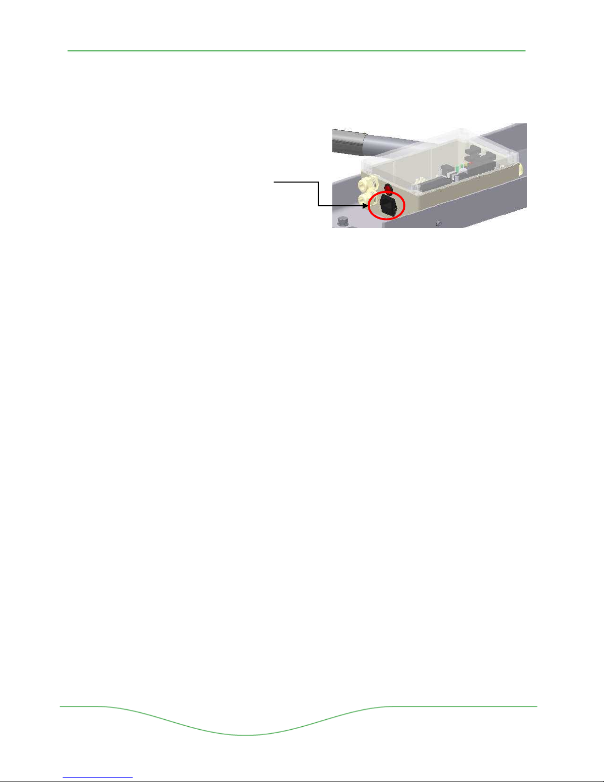
For 110/220 VAC single phase Mains Power, a 2.5 Amp fuse is located inside the Mains
Power Receptacle as noted in Figure 5.18. An integrated fuse holder is located in the
lower portion of the receptacle.
Units using dual phase 220 VAC, requires an additional factory supplied fuse located
inside the control box. Reference electrical drawings in the appendix 11.2 for additional
information.
Receptacle with Fuse Holder
Figure 5-18: Mains Power Receptacle
Boon Edam Inc.
402 McKinney Parkway Version: Rev A6 10/28//2011
Tel. 910-814-3800 fax 910-814-3899 Issue: THT-100-IMM-USA
Page 34
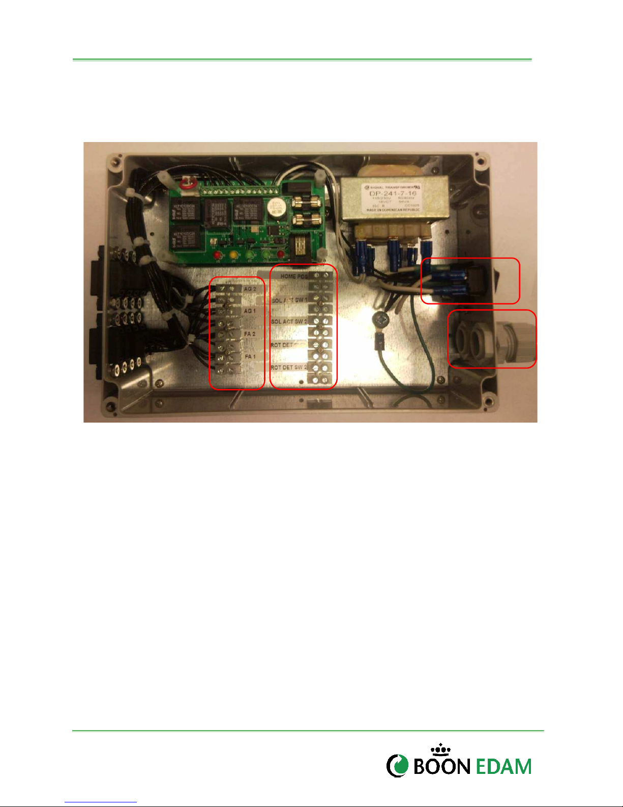
33
X1 X2
MCB Control Board
Transformer
Cable Glands
Mains Power
Installation and Maintenance Manual
Access Control Integration
The Access Control System (ACS) connections are terminated to the X1 and X2 terminal strips
located inside the main control box. The following integration connections are available:
Connector
Fuse Holder
Figure 5-19: Main Control Box
Terminal Strips
X1 Terminal Strip
• AG2 - Access Grant CW
• AG1 - Access Grant ACW
• FA 2 - Fire Alarm CW
• FA 1 - Fire Alarm ACW
X2 Terminal Strip
• HOME POS – Home Position
• SOL ACT SW1 – Solenoid Activation Switch 1
• SOL ACT SW2 – Solenoiod Activation Switch 2
• ROT DET SW 1 – Rotation Detection Switch ACW
• ROT DET SW 2 - Rotation Detection Switch CW
for ACS Wiring
Version : 10//28/2011
Issue : THT-100-IMM-USA REV A6
Page 35
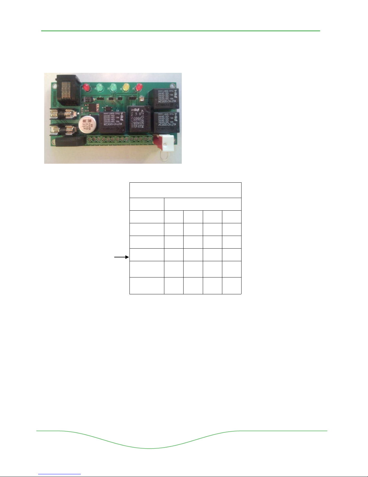
THT-100
D11 D12
D2 D3 D1
J2 J7 J4 J3
R1 FS/FL Jumper
Fuse 1 and 2
Serial
34
5.10 Configuration
A series of jumpers are pre-configured on the main control board(s) specific to each
configuration (i.e., Fail Safe/Fail Lock). Each board is configured for a single direction of travel:
Board Layout
• Jumpers - J2, J3, J4, J7 (reference Jumper
Port
Figure 5-20: MCB Detail
Configuration Chart for specific settings).
• R1 – Potentiometer to adjust time out
duration.
• Staus LEDs
D11 – Fault Condition Indicator
D12 – Normal Operation Indicator
D1 – Lock Activated
D2 – Pulse Trigger
D3 – Pulse Relay
• Fail Safe/Fail Lock Jumper
• Fuses – 1.5 Amp
• Serial Port Interface
JUMPER CONFIGURATIONS
FUNCTION
NO PULSE OR
TIME OUT CIRCUIT
TIMEOUT CIRCUIT
ONLY
PULSE CIRCUIT
ONLY
PULSE AND TIME
Factory Default Settings
OUT CIRCUITS
SERIAL PORT
INTERFACE
W/OUT TIMEOUT
SERIAL PORT
INTERFACE
W/TIMEOUT
Figure 5-21: Jumper Configuration Chart
Configuration Definitions:
• Time Out Relay – Provides a time out duration after a valid access is granted. The
setting of potiometer R1 determines the holding duration of this relay. After the hold time
expires the unit will return to its standby state.
• Pulse Relay – When the Access Control System sends an access grant signal to the
MCB, a one-shot pulse will automatically generate internally; regardless of how long the
ACS input signal is held.
• Serial Port Interface – Allows the MCB to react to wet voltages (3-25vdc) in leu of dry
contact inputs on the X1 terminals. Options for signal transmission TD or SD (Transmit
Data), DTR (Data Terminal Ready), RTS (Request to Send Data).
Start-up
PINS TO JUMP ON JUMPER:
J2 J3 J4 J7
2-3 2-3 - -
2-3 1-2
- 2-3
- 1-2
- 2-3
- 1-2
-
1-2
1-2 1-2
-
-
-
1-2
-
-
Boon Edam Inc.
402 McKinney Parkway Version: Rev A6 10/28//2011
Tel. 910-814-3800 fax 910-814-3899 Issue: THT-100-IMM-USA
Page 36
35
WARNING!
Installation and Maintenance Manual
Persons should remain clear of the THT-100 top channel mechanism’s
moving parts.
5.11 General
The THT-100 will be pre-configured by Boon Edam and is ready for general use after
proper installation. Setting up the THT-100 for operation can be accomplished by using
the start procedure as described below.
• Rotate the unit to its proper resting position.
• Turn power to the main control box on. The solenoids should engage and you will hear the
lock(s) pull in.
• Green LED on MCB indicates unit is ready for operation.
• At this point, the unit is ready for operation.
5.12 Time Out Relay Adjustment
THT-100 units are equipped with a time out relay preset at the factory for approximately
10 second time out delay after a valid card read (see figure 5.16).
To adjust this setting carefully turn the potentiometer clockwise to minimize this time
(approx seven seconds), or counter-clockwise to increase this setting (max time approx
20 seconds).
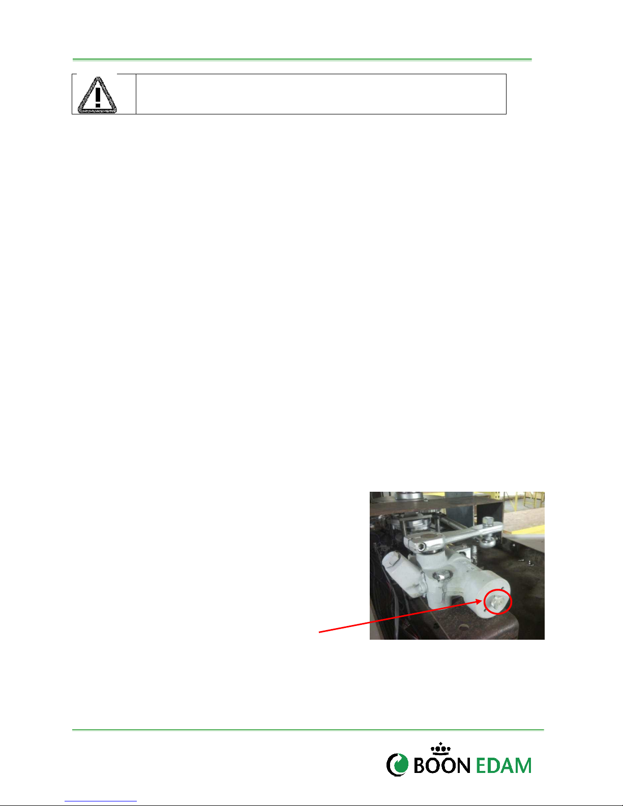
5.13 Speed Control Adjustment (Optional)
THT-100 units equipped with an optional speed control system are set during factory
assembly but may require additional field adjustment to achieve the desired dampening
during position cycle. The following procedure can assist in finalizing this setting.
• Rotate the unit until you can feel the dampening system take effect (If dampening does
not take effect, the rotor arms will slam against the locking mechanism).
• If more dampening is necessary, turn the speed control adjustment wheel clockwise to
increase the resistance of the dampening
mechanism until the desired force is applied.
Note: too much dampening can cause the unit to
brake too early which affects the throughput of the
unit and may damage the equipment.
• If less dampening is necessary, turn the speed
control adjustment wheel counter-clockwise to
decrease the amount of dampening. Note: too little
dampening can result in the unit slamming against
the locking system and may damage the equipment.
Adjustment Wheel
Figure 5-22: Speed Control
Version : 10//28/2011
Issue : THT-100-IMM-USA REV A6
Page 37
THT-100
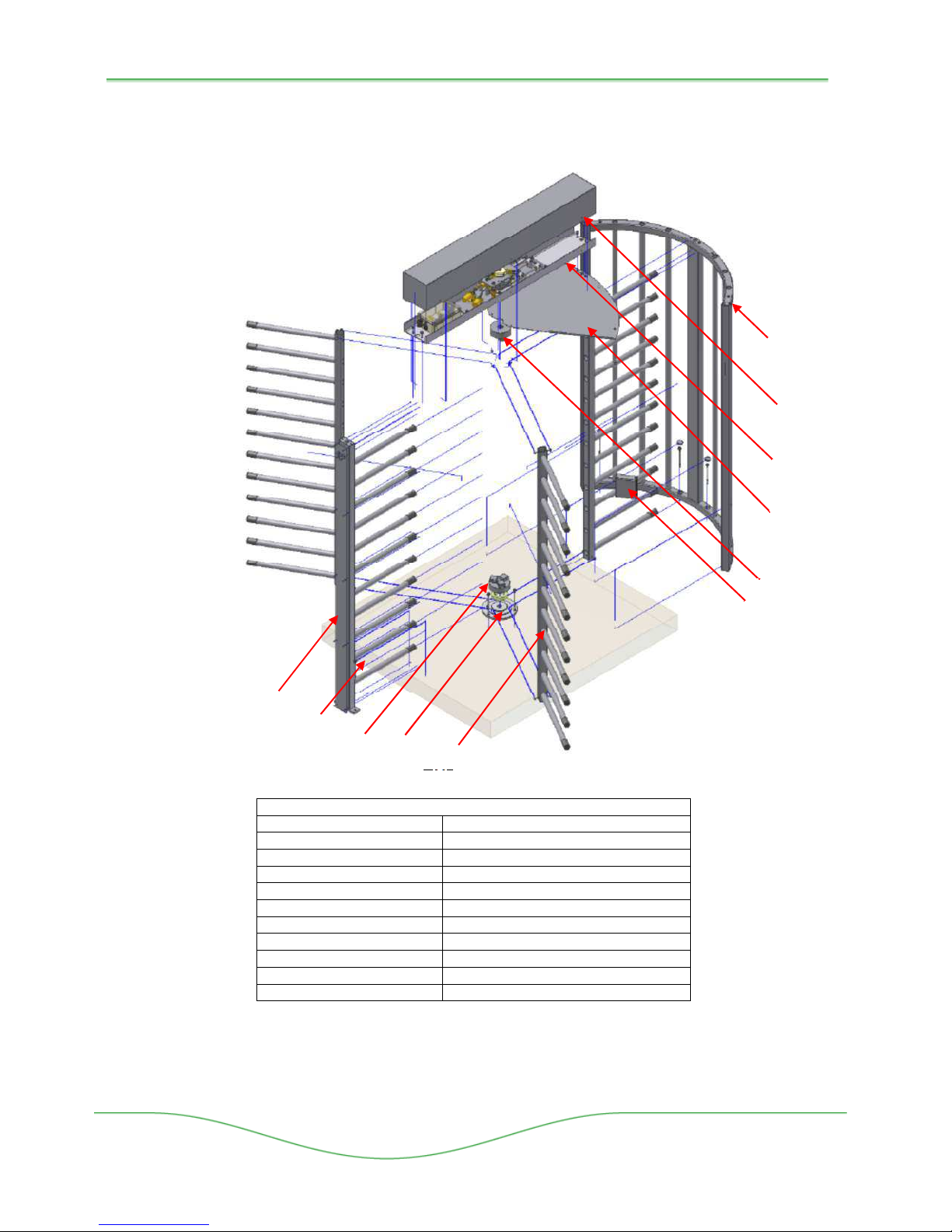
6 Parts Overview
6.1 THT100- Exploded View
D02
D01
C02
Figure 6-1: THT-100 Exploded View
A01 Side Shield
A02 Card Reader Bracket (Optional)
B01 Top Channel Cover
B02 Top Channel Mechanism
B03 Ceiling Plate
C01 Top Flange Assembly
C02 Bottom Flange Assembly
C03 Base Plate Assembly (w/Bearing)
C04 Rotor Arm Assembly (3 Each)
D01 Barrier Assembly
D02 Barrier Post Cover
Figure 6-2: THT-100 Parts Description
C03
C04
Part Description
36
A01
B01
B02
B03
C01
A02
Boon Edam Inc.
402 McKinney Parkway Version: Rev A6 10/28//2011
Tel. 910-814-3800 fax 910-814-3899 Issue: THT-100-IMM-USA
Page 38

37
Installation and Maintenance Manual
SAFETY INSPECTIONS AND MAINTENANCE
7 Safety Inspections
All security entrance equipment requires a simple daily safety inspection to ensure the system is
functioning properly. This test must be performed by the owner or facility manager. Should any
safety feature fail to pass the test, the unit must be disabled until repair is complete. It is
recommended that a simple log of such inspections is kept for security and safety purposes.
7.1 Daily Inspection
• Visually inspect area for any trip hazards, sharp edges or other damage.
• Inspect both incoming and outgoing traffic scenarios.
• Inspect the entire unit for unusual noises.
• Present a valid card and manually rotate the unit in the authorized direction(s).
• Verify that traffic lights turn the appropriate colors (if equipped).
• After rotation, the unit should position and lock.
8 Maintenance
For detailed troubleshooting information please refer to chapter 9 Troubleshooting.
8.1 Weekly Cleaning
It is recommended that a minimum weekly cleaning of the equipment be performed to assure
proper operation and optimal function.
• Clean exterior finish with a damp cotton cloth. Special finishes can be damaged by
abrasive cleaning agents.
• Wipe lens covers on cabinets with soft cloth to clean any buildup from obstructing
beams.
•
• Clean optional lexan panels with soft cloth and mild soap. Do not use chemical or
abraisive cleaners on lexan units.
8.2 Semi-Annual Planned Maintenance
It is recommended that a minimum of two planned maintenance inspections be performed on
the equipment by an Authorized Boon Edam agent to assure proper operation and optimal
function.
General Inspection
• The technician should report to a contact and always ask if there are any particular
issues with the units.
• Make sure to write down any remarks made by the customer on the checklist.
• Perform a visual check for broken materials (sharp edges) or other damages.
• Check the whole unit for unusual noises.
• Check the details of the location on the maintenance checklist (product type, product
no.).
• Remove the top channel cover to gain access to the control mechanism and electronics.
• Always check out with contact and/or reception.
Version : 10//28/2011
Issue : THT-100-IMM-USA REV A6
Page 39

THT-100
Electrical
• Check the safety functions of unit (speed control, heel guards etc., if equipped).
• Perform a function test, ACS controls.
• Check the operation of the solenoids.
• Check earth grounding.
• Check the electrical wiring connections, especially for damage near moving parts.
Mechanical
• Check the anchor mountings and fasten where needed.
• Check the movement of bottom bearing and mounting anchors. Lubricate bearing
through grease zerk.
• Check the whole installation for correct alignment with floor (surroundings)
• Inspect locking pawls for wear. Ensure they properly lock and hold.
• Inspect Key override functions
• Inspect Fire Alarm functions (if connected)
• Inspect Power failure functions
• Inspect Dampening system (if equipped) to ensure rotor arms rotate and rest smoothly.
38
Boon Edam Inc.
402 McKinney Parkway Version: Rev A6 10/28//2011
Tel. 910-814-3800 fax 910-814-3899 Issue: THT-100-IMM-USA
Page 40
39
H
K
J U S T
H E C K
J U S T
1.
General
5 Functions
2.
Mechanism
3.
Electrical
4
Rotor Arms
Arm Condition
Installation and Maintenance Manual
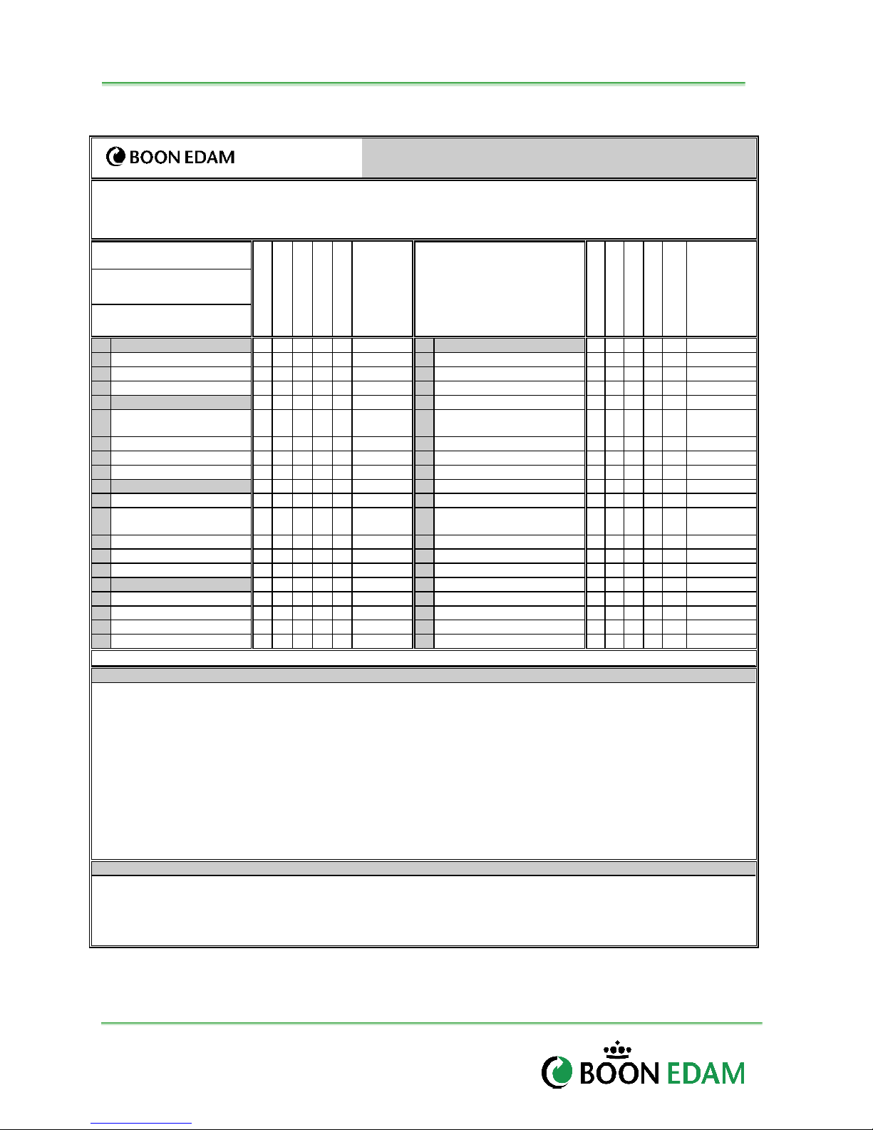
8.3 Maintenance checklist
Maintenance Checklist:
THT-100 ( )
Project no.: . . . . . . . . . . . . . . . . . . . . . . . .
Project Name: . . . . . . . . . . . . . . . . . . . . . . . .
Serial no. : . . . . . . . . . . . . . . . . . . . . . . . .
Location : . . . . . . . . . . . . . . . . . . . . . . . .
Date:
Work Order no. :
Name technician :
C
E
C
G
A
L
R
D
E
E
A
A
S
N
E
C
A Visual X X O
B Noise X O
O
K
N
O
T
E
S
A LED Functions X X O Option
b Access control system pulse X X O Duration
c Gen Operation X X O
d Power Fail action X X O
A Speed Control unit
X X O
e Fire Alarm Function X O
(operat.+noise)
B Top Plate Bolts X X O
C Centering Disc Blocks X X O
f Wiring (connections) X O
g
h
i
A Inspect Fuses X O
B Main Control Board
X O
j
k
Functions
C Cable Connections X O
D Microswitches X X O
l
A Mounting Bolts X X O
B End Caps X O
C
X X O
D Bearing X X X O
√√√√ = Checked and OK X = Work to be carried out
Recommendations + Remarks
. . . . . . . . . . . . . . . . . . . . . . . . . . . . . . . . . . . . . . . . . . . . . . . . . . . . . . . . . . . . . . . . . . . . . . . . . . . . . . . . . . . . . . . . . . . . . . . . . . . . . . . . . . . . . . . . . . . .
. . . . . . . . . . . . . . . . . . . . . . . . . . . . . . . . . . . . . . . . . . . . . . . . . . . . . . . . . . . . . . . . . . . . . . . . . . . . . . . . . . . . . . . . . . . . . . . . . . . . . . . . . . . . . . . . . . . .
. . . . . . . . . . . . . . . . . . . . . . . . . . . . . . . . . . . . . . . . . . . . . . . . . . . . . . . . . . . . . . . . . . . . . . . . . . . . . . . . . . . . . . . . . . . . . . . . . . . . . . . . . . . . . . . . . . . .
. . . . . . . . . . . . . . . . . . . . . . . . . . . . . . . . . . . . . . . . . . . . . . . . . . . . . . . . . . . . . . . . . . . . . . . . . . . . . . . . . . . . . . . . . . . . . . . . . . . . . . . . . . . . . . . . . . . .
. . . . . . . . . . . . . . . . . . . . . . . . . . . . . . . . . . . . . . . . . . . . . . . . . . . . . . . . . . . . . . . . . . . . . . . . . . . . . . . . . . . . . . . . . . . . . . . . . . . . . . . . . . . . . . . . . . . .
. . . . . . . . . . . . . . . . . . . . . . . . . . . . . . . . . . . . . . . . . . . . . . . . . . . . . . . . . . . . . . . . . . . . . . . . . . . . . . . . . . . . . . . . . . . . . . . . . . . . . . . . . . . . . . . . . . . .
. . . . . . . . . . . . . . . . . . . . . . . . . . . . . . . . . . . . . . . . . . . . . . . . . . . . . . . . . . . . . . . . . . . . . . . . . . . . . . . . . . . . . . . . . . . . . . . . . . . . . . . . . . . . . . . . . . . .
. . . . . . . . . . . . . . . . . . . . . . . . . . . . . . . . . . . . . . . . . . . . . . . . . . . . . . . . . . . . . . . . . . . . . . . . . . . . . . . . . . . . . . . . . . . . . . . . . . . . . . . . . . . . . . . . . . . .
. . . . . . . . . . . . . . . . . . . . . . . . . . . . . . . . . . . . . . . . . . . . . . . . . . . . . . . . . . . . . . . . . . . . . . . . . . . . . . . . . . . . . . . . . . . . . . . . . . . . . . . . . . . . . . . . . . . .
. . . . . . . . . . . . . . . . . . . . . . . . . . . . . . . . . . . . . . . . . . . . . . . . . . . . . . . . . . . . . . . . . . . . . . . . . . . . . . . . . . . . . . . . . . . . . . . . . . . . . . . . . . . . . . . . . . . .
. . . . . . . . . . . . . . . . . . . . . . . . . . . . . . . . . . . . . . . . . . . . . . . . . . . . . . . . . . . . . . . . . . . . . . . . . . . . . . . . . . . . . . . . . . . . . . . . . . . . . . . . . . . . . . . . . . . .
Signed as correct by client:
On behalf of client (please print):
. . . . . . . . . . . . . . . . . . . . . . . . . . . . . .
Function: . . . . . . . . . . . . . . . . . . . . . . (Signature and Date)
Table 8.1: Maintenance checklist
C
C
G
A
L
E
A
N
O
R
D
K
E
A
S
E
N
O
T
E
S
Version : 10//28/2011
Issue : THT-100-IMM-USA REV A6
Page 41
THT-100
TROUBLESHOOTING
9 Troubleshooting
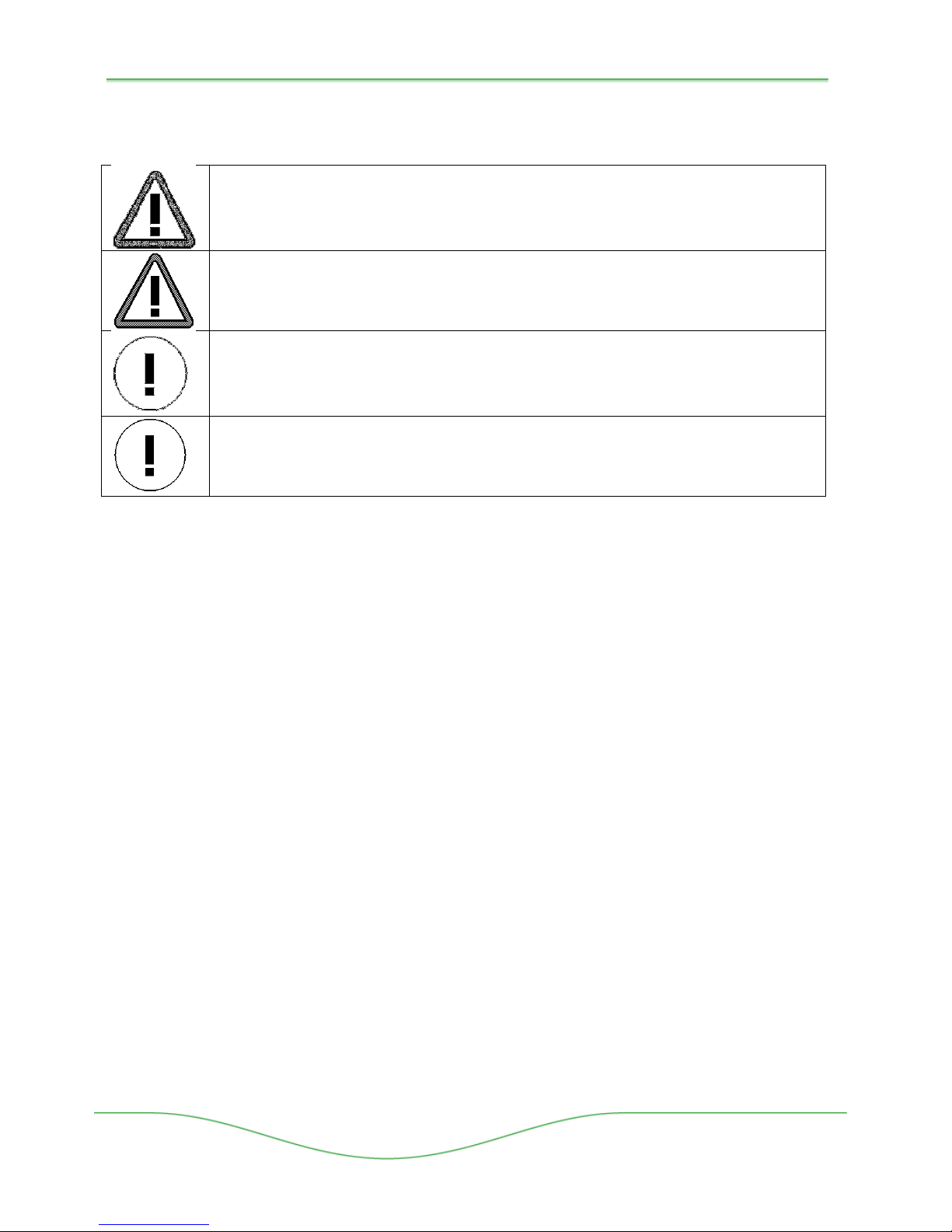
WARNING!
Switch off the power supply to the product before working on the product.
WARNING!
Risk of personal injury or loss of life.
CAUTION!
All installation and maintenance work on the product must be carried out by
Boon Edam personnel or by an approved agent.
CAUTION!
The material may be damaged or the operation of the system affected.
40
9.1 Control Box and Main Control Board
• Check the two 1.5A fuse and mains power supply 2.5A fuse(s) when the system does
not appear to be powered up. The LCD’s on the MCB will be blank with visible read out
if power is not present. The fuses are located in the power connection box on the MCB.
• Powering down the entire THT-100 by shutting down the power and waiting for approx. 30
seconds before powering it back up.
• Let the unit fully initialize.
• Check connection of electrical cables to control box. Verify proper label and plug
connections.
9.2 Top Channel Mechanism
• Speed control dampening (option). If the speed control system is not dampening
properly, adjust the shock absorber system until the desired results are achieved.
• If unit is not locking properly, inspect proper function of the locking solenoids, power
supply and connection plugs of the control box.
• Inspect spring tension of locking pawl system and spings to ensure proper tension.
• If the unit does not unlock properly, inspect card reader functions and connection of
access control wiring inside the main control box.
9.3 Rotor Assembly and Frame
• Loose rotor arms. Check M10 bolt connections of rotor arm assemblies.
• Incorrect Home Position. Check alignment of Top Channel shaft pin and top flange
guide.
Boon Edam Inc.
402 McKinney Parkway Version: Rev A6 10/28//2011
Tel. 910-814-3800 fax 910-814-3899 Issue: THT-100-IMM-USA
Page 42

41
Installation and Maintenance Manual
TECHNICAL SPECIFICATIONS
10 Technical specifications
10.1 Control
Main Control Board: 24VDC, 1.25 Amp max draw.
Main Transformer:
10.2 Solenoids
Power supply: 24 VDC
Duty Cycle: 100%ed
Temp. range: -20°C / +55°C
Response time: ±20ms
10.3 Complete barrier
Type: Three-wing (optional 4th wing) steel, stainless steel or aluminum access control
Application: Manual turnstile that allows controlled access to authorized persons
Capacity: Controlled access (1 direction), nominal capacity: 15 to 30 persons/minute.
Finish: (Various) Stainless steel, AISI 304 with a #4 grain finish, Powder-coated steel,
Rotor Arms: (Various) Stainless steel, AISI 304 with a #4 grain finish, Powder-coated steel,
Overall height: 89” (2261mm) overall height. 81”(2057mm) walk through height.
Weight: Approx: 800lbs (360kg), including crate (standard version)
Installation: Typical Concrete type anchors
Cabling: Power supply, fire alarm & communication cables (see drawings)
Power supply: Configurable 110-240 VAC, 50/60 Hz
Mains Fuse: 2.5 Amp
110/220VAC primary. 20VAC secondary output. CSA and UL approved.
mechanical turnstile.
galvanized zinc plated steel, anodized aluminium finish depending upon
model.
galvanized zinc plated steel, anodized aluminium finish, Lexan arms,
depending upon model.
Version : 10//28/2011
Issue : THT-100-IMM-USA REV A6
Page 43

THT-100
Part
APPENDICES
11 Appendices
11.1 Spare Part list
42
Number Description Comment
10920 Solenoid Assembly Cable Standard Solenoid with lead wires and plug.
50040224 Mains Connector w/Fuse Control Box
101-009 Transformer, 110/220VAC Control Box
10905 Mains Power Switch Control Box
10904 Main Control Board Control Box
2.5A Fuse Fuse in mains switch
10927 1.5A Fuse Fuse in MCB
17001 Bottom Bearing B334(INA) Lower center bearing assembly
100-042 Top Bearing (GYA108RRB) Upper center bearing assembly
100-128 Locking Pawl Spring LH Typical for Fail Safe
100-129 Locking Pawl Spring RH Typical for FS/FL Combo
100-131 Connecting Spring Typical for FS locking
101-012 2 Way Microswitch Home Position/Rotation Det.
101-015 Microswitch Gasket Isolation material for microswitch
1>5 Units 6>Units
Boon Edam Inc.
402 McKinney Parkway Version: Rev A6 10/28//2011
Tel. 910-814-3800 fax 910-814-3899 Issue: THT-100-IMM-USA
Page 44
43
Installation and Maintenance Manual
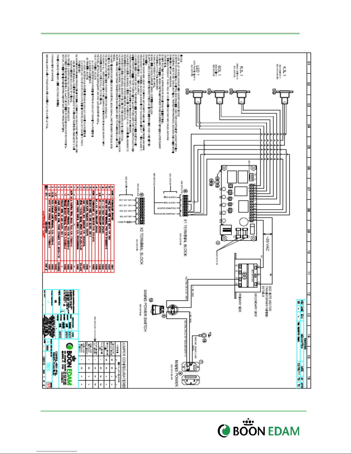
11.2 Electrical Schematics
Version : 10//28/2011
Issue : THT-100-IMM-USA REV A6
Table 11.1: Electrical Schematic
Page 45
THT-100
44
11.3 THT100- Tandem Unit
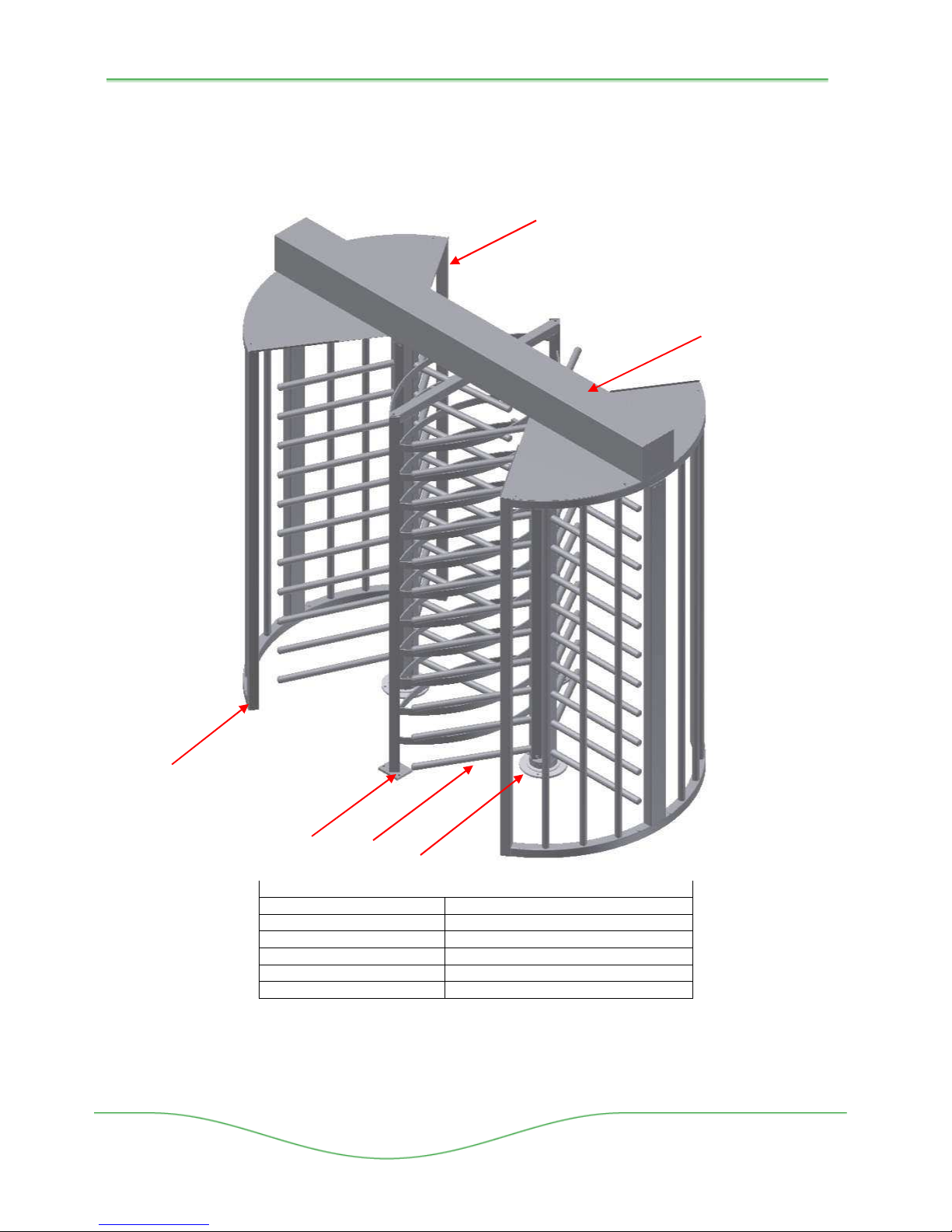
The THT-100 is available in a Tandem Unit which incorporates two sets of rotor arms and
mechanisms into one extended top channel unit as illustrated in figure below. Installation
follows the typical THT100 unit.
A05
A06
A01
A02
A01 Side Shields
A02 Tandem Barrier Assembly
A03 Rotor Arm Assembly (6 Each)
A04 Base Plate Assemblies (w/Bearings)
A05 Ceiling Plates
A06 Top Channel Mechanism w/cover
Boon Edam Inc.
402 McKinney Parkway Version: Rev A6 10/28//2011
Tel. 910-814-3800 fax 910-814-3899 Issue: THT-100-IMM-USA
A03
A04
Part Description
Figure 11.2: THT100 Tandem Unit
Page 46
45
Installation and Maintenance Manual
11.4 TASTG – Curved Shield Tandem Unit
11.5 THT-100TL – Tandem Unit.
Figure 11-1, TASTG
Version : 10//28/2011
Issue : THT-100-IMM-USA REV A6
Figure 11-2, TL Tandem
Page 47

THT-100
46
Enclosures
In this chapter specific information regarding the project can be added.
Boon Edam Inc.
402 McKinney Parkway Version: Rev A6 10/28//2011
Tel. 910-814-3800 fax 910-814-3899 Issue: THT-100-IMM-USA
Page 48

47
Installation and Maintenance Manual
Royal Boon Edam International B.V.
Ambachtstraat 4 / 1135 GG EDAM
P.O. Box 40 / 1135 ZG EDAM
The Netherlands
T +31 (0)299 38 08 08
F +31 (0)299 37 28 59
Boon Edam B.V.
Ambachtstraat 4 / 1135 GG EDAM
P.O. Box 40 / 1135 ZG EDAM
The Netherlands
T +31 (0)299 38 08 08
F +31 (0)299 37 28 59
Boon Edam Nederland B.V.
Ambachtstraat 4 / 1135 GG EDAM
P.O. Box 40 / 1135 ZG EDAM
The Netherlands
T +31 (0)299 38 08 08
F +31 (0)299 38 08 41
Boon Edam A.S.
Arnst. Arnebergsvei 30
Postbox 430
N-1324 LYSAKER
Norway
T +47 (0)67 10 3340
F +47 (0)67 10 3344
Boon Edam Sweden AB
Kuttervägen 1 / S-183 02 TÄBY
P.O. Box 2034 / S-183 02 TÄBY
Sweden
T +46 (0)8 753 60 30
F +46 (0)8 753 61 30
Boon Edam LLC
Leningradsky Prospect 39
Building 14, Floor 4, Room 416
125167 MOSCOW
Russian Federation
T +7 (0) 496 0249
Boon Edam Ireland Ltd.
Unit 1 Naas Road Business Park,
Muirfield Drive, Naas Road,
DUBLIN 12
Ireland
T +353 (0)1 460 1420
F +353 (0)1 460 1415
Boon Edam Ltd.
Holland House
Crowbridge Road, Orbital Park
ASHFORD KENT TN24 0GR
United Kingdom
T +44 (0)1233 505996
F +44 (0)1233 505909
Boon Edam GmbH
Lise Meitner Straße 1
45659 RECKLINGHAUSEN
Germany
T +49 (0)2361 58202-0
F +49 (0)2361 58202-10
Boon Edam BVBA/SPRL
Welvaartstraat 14-1
Industriezone Klein Gent
B-2200 HERENTALS
Belgium
T +32 (0)14 21 67 17
F +32 (0)14 21 67 29
Boon Edam France S.A.S.
ZA Les Doucettes
3 Avenue des Morillons
95146 GARGES-LES-GONESSE Cedex
France
T +33 (0)1 30 11 05 05
F +33 (0)1 39 86 71 10
Boon Edam Entrance Technology
(India) Private Limited
602, Ascot Centre
Sahar Airport Road, Andheri (E)
Mumbai 400099
India
T +91 22 28257582
F +91 22 28257490
Boon Edam Spain S.L.
C/Palència, 14-16 1° 4a
08027 BARCELONA
Spain
T +34 (0)93 408 7255
F +34 (0)93 408 3446
Boon Edam Inc.
402 McKinney Parkway
LILLINGTON
North Carolina 27546-9336
United States of America
T +1 (910) 814 38 00
F +1 (910) 814 38 99
Boon Edam Japan Ltd.
4th Floor Kyohachi Building
1-16-5 Shinkawa Chuo-ku
TOKYO 104-0033
Japan
T +81 (0) 3 5117 26 51
F +81 (0) 3 5117 26 52
Beijing Boon Edam Entrance
Technology Co. Ltd.
No.10 Tong Ji Bei Lu,
Beijing Economic & Technological
Development Area
BEIJING 100176
China
T +86 (0)10 67 87 77 66
F +86 (0)10 67 87 78 05
Boon Edam Hong Kong Ltd.
Unit 803, 8/F., Tamson Plaza, No. 161
Wai Yip Street,
Kwun Tong, KOWLOON
Hong Kong
T +852 2793 1810
F +852 2793 0862
Version : 10//28/2011
Issue : THT-100-IMM-USA REV A6
www.boonedam.com
 Loading...