

Page 1
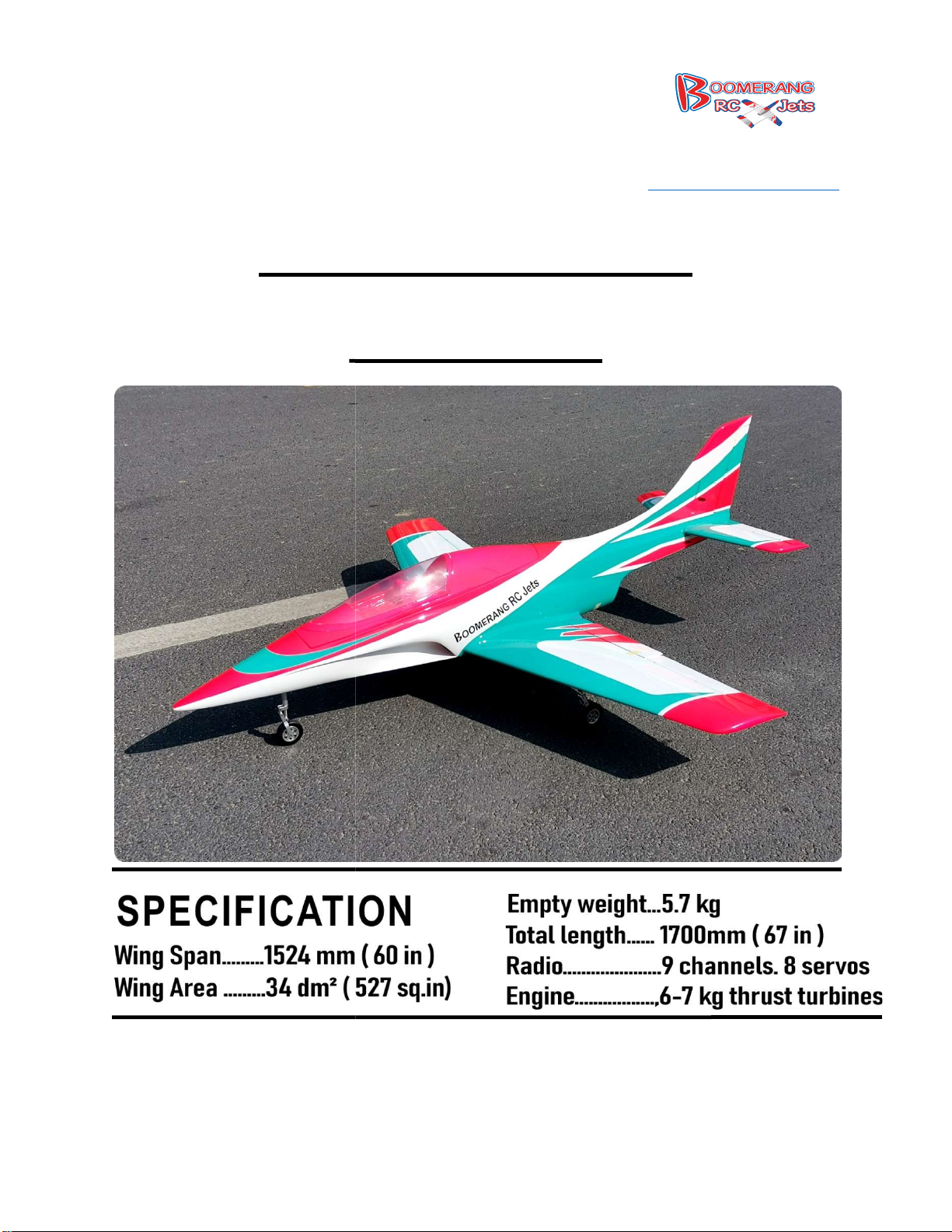
Boomerang Lancer
Instruction
8768 IN-
236, Middletown IN47356
www.boomerangrcjets.com
1-765-548-3757
Page 2
Required for Flight:
and examine all components.
Make sure all hinges fit into the
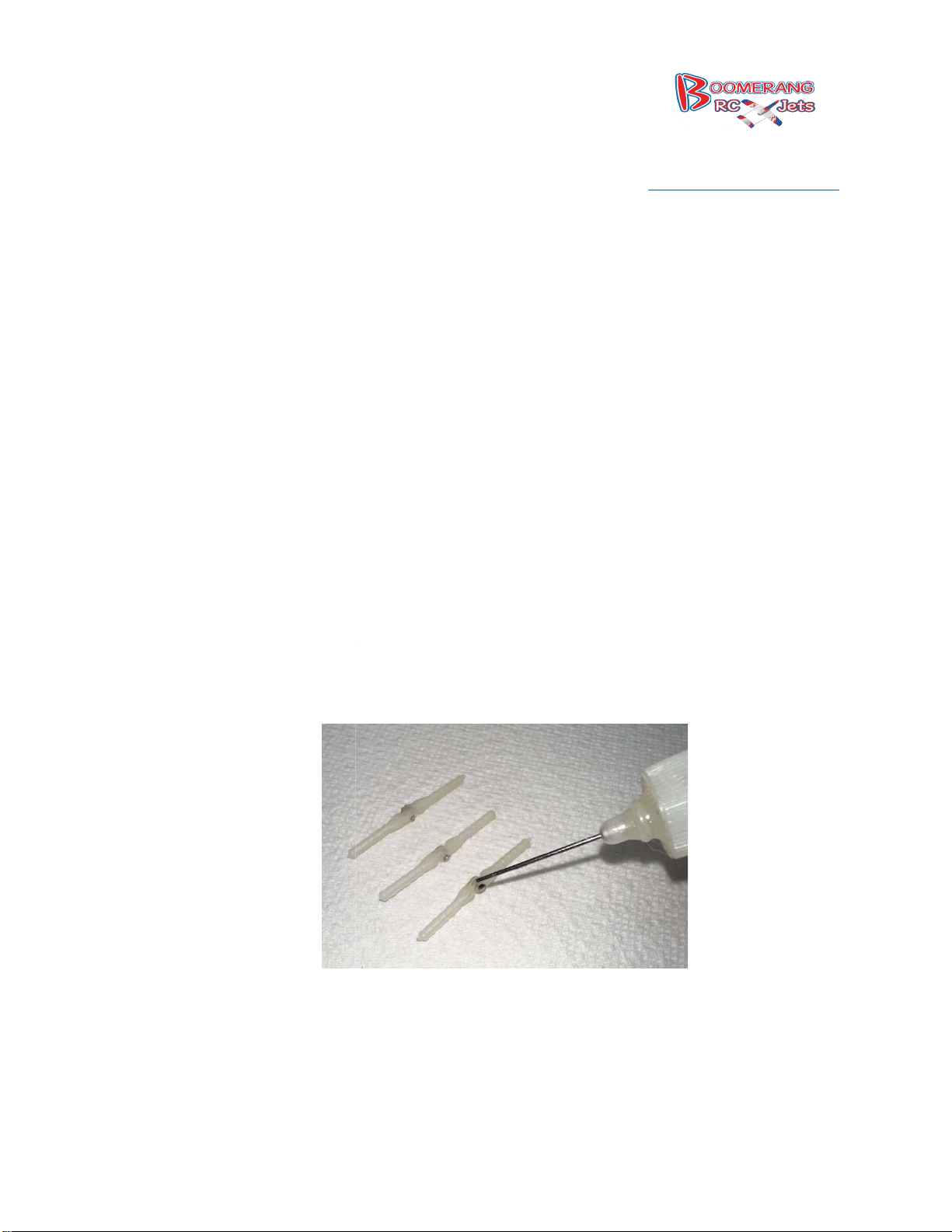
Remove all hinges and place on a paper towel and apply a small amount of oil along the pin on
each of the hinge to prevent the glue from sticking and gluing
Locate one of the short control horn screws, 36.5mm with corresponding washer and nut as well
236, Middletown IN47356
www.boomerangrcjets.com
ARF Jet Kit
(1) Electric Retract System w/ Electric Brakes
Carbon Fiber Wing and Stab Tubes
on the other side.
the hinge so it will not move.
8768 IN-
What's Included:
1-765-548-3757
(1) 9+ Channel Transmitter
(1) 9+ Channel Receiver
(1) 50-70N Sized Turbine
(6) Standard Sized Servos
(2) Mini Servos
1. Unpack the Lancer
Hinging
2.
3.
(1) Boomerang Lancer
(1) Composite Fuel Tank
(1) Hardware Package
holes and line up with their respective hole
4.
as the rudder.
Page 3
5.
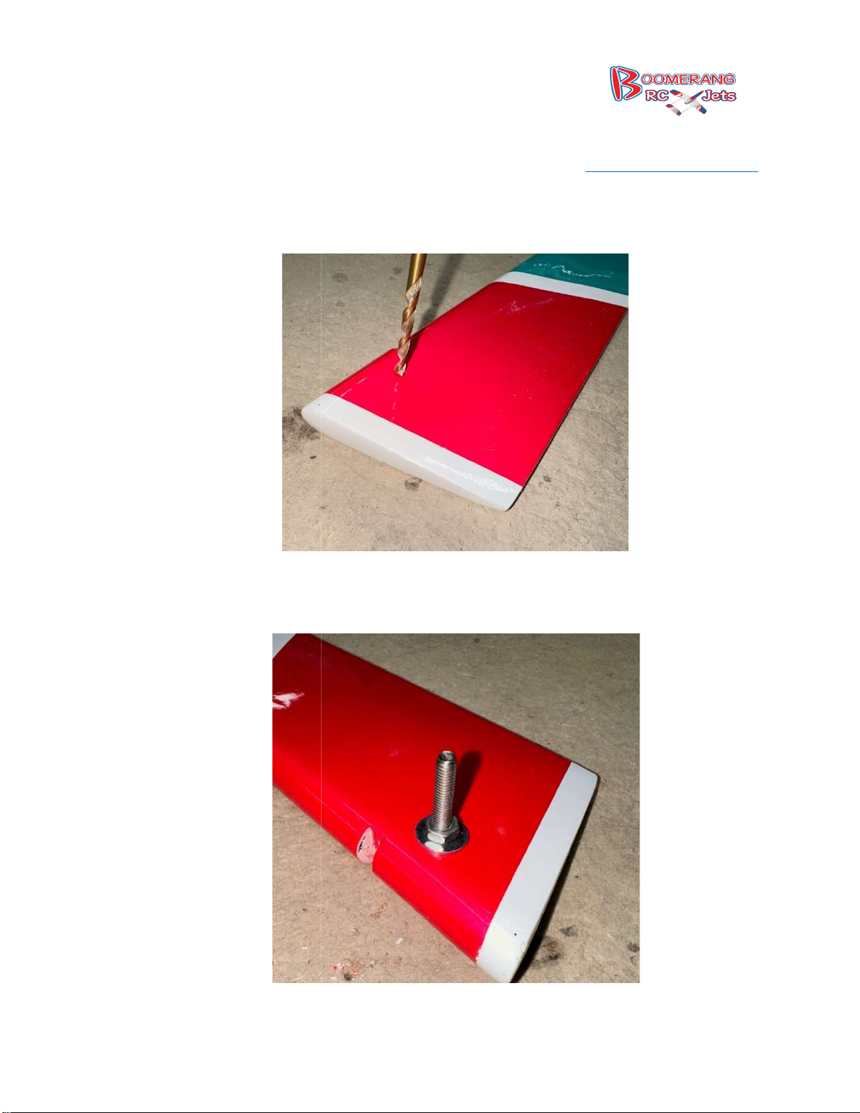
Using a 3.5mm drill bit drill the hole in the rudder for the control horn bolt to go through. The
the location marked as to where to drill the hole. We find it easier to do this before
gluing the hinges for the rudder.
2.5mm driver install the control horn through the rudder and once through put a tiny
drop of Loctite on to secure the bolt
236, Middletown IN47356
www.boomerangrcjets.com
rudder has
8768 IN-
1-765-548-3757
6. Using a
in place.
Page 4
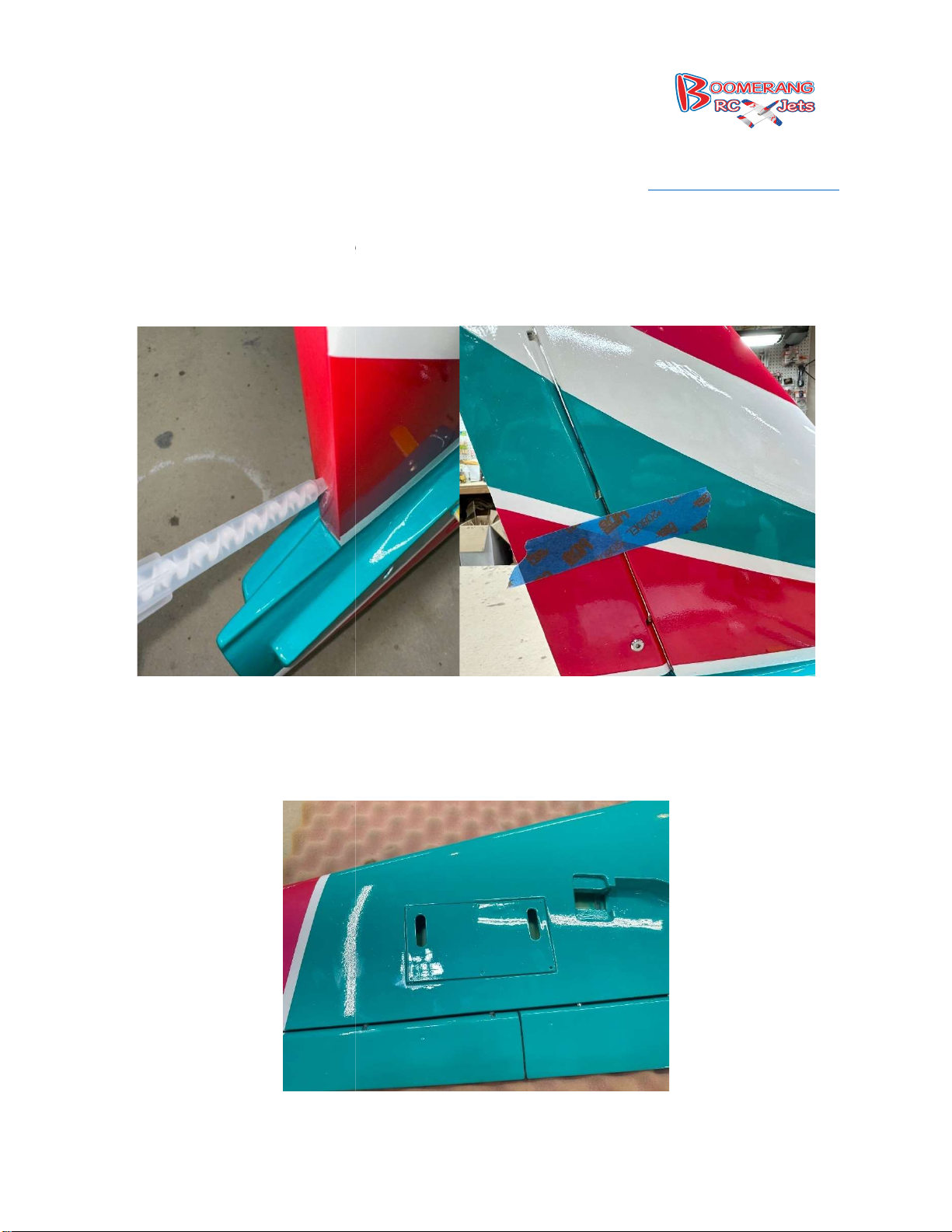
We chose to use Hysol inorder to make gluing the hinges quick and easy. With the Hysol tip it
was easy to control the amount of glue going into the hinge hole and exactly where it was going.
Once the glue was put in the holes the hinges wer
Locate the servo hatch for each wing, the servo arm cut outs go to the leading edge of the wing.
236, Middletown IN47356
www.boomerangrcjets.com
e lined up and installed and the surface put on
8768 IN-
1-765-548-3757
7.
and taped in place.
Wings
1.
Page 5
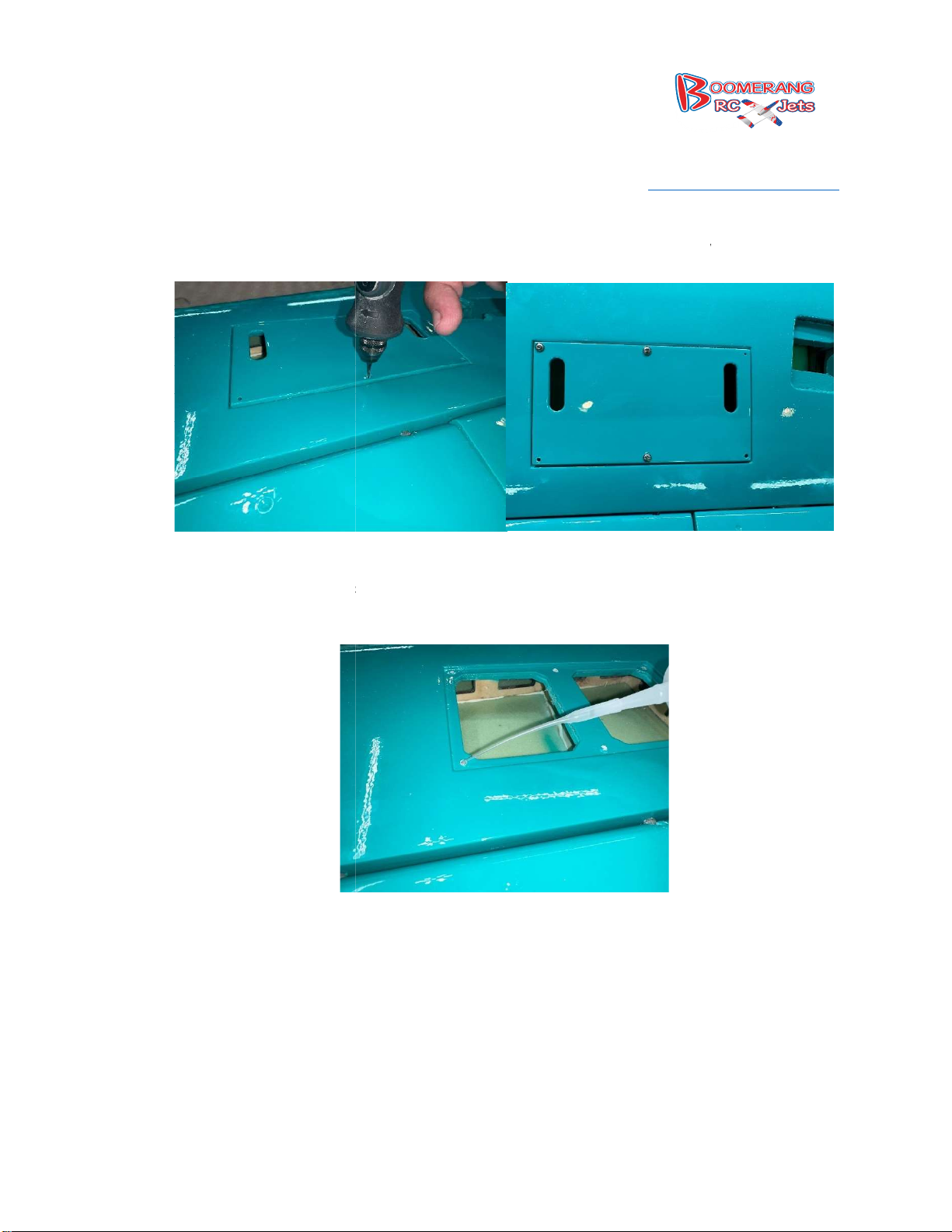
2.
Using a 1.2mm drill bit drill the 6 holes to secure the Hatch to bottom of
Test fit the hatch with the 6x Phillips head 13mm screws to secure the hatch and then remove
3 drops of thin CA into the hole in the wood to harden the threads. Let the
CA dry on its own, do not use accelerator.
236, Middletown IN47356
www.boomerangrcjets.com
the wing.
3.
the hatch and put 2-
8768 IN-
1-765-548-3757
Page 6
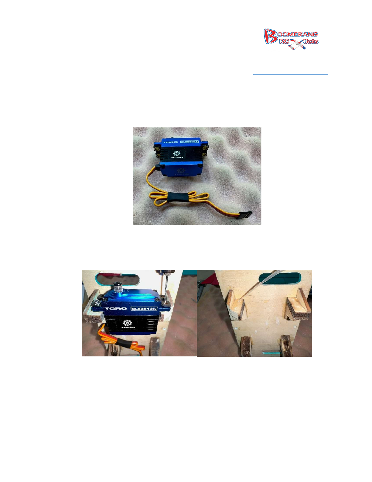
4.
Assemble your servo, we like to tie up the servo lead and then later we will run all the
extensions to the servo locations. If you ever need to do any work in the servo bay it makes it
easier to drop the hatches and get in there.
servo into the hatch and using the 1.2 mm drill bit drill the holes for the servo
screws, then tap them with the servo screws and put a drop or two of thin CA in each hole and
236, Middletown IN47356
www.boomerangrcjets.com
5. Test fit the
8768 IN-
1-765-548-3757
allow to air dry.
Page 7
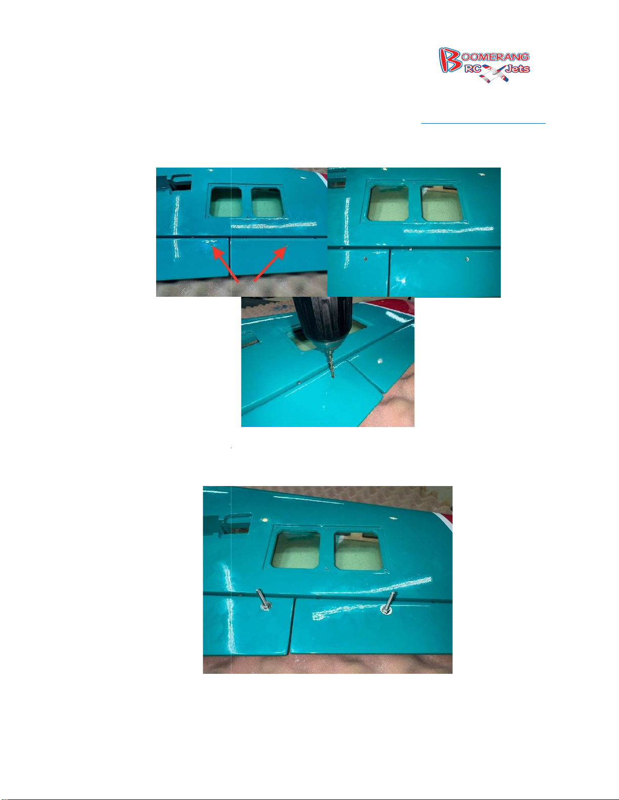
6.
Using your 3.5 mm drill bit drill the holes for
Now locate the 40 mm control horn screws, washers and nuts and thread them into the flap and
aileron. Remember just a drop of Loctite
236, Middletown IN47356
www.boomerangrcjets.com
the control horns in the ailerons and flaps.
o keep the nut secure is all that is needed.
8768 IN-
1-765-548-3757
7.
t
Page 8
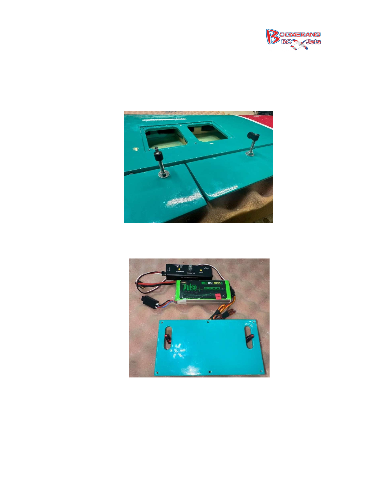
8. Thread on
the nylon portion of the control horn to the bolts so that they are flush with the top
Center your servos now and install the servo arms for your ailerons and flaps.
236, Middletown IN47356
www.boomerangrcjets.com
of the bolt.
9.
8768 IN-
1-765-548-3757
Page 9
10.
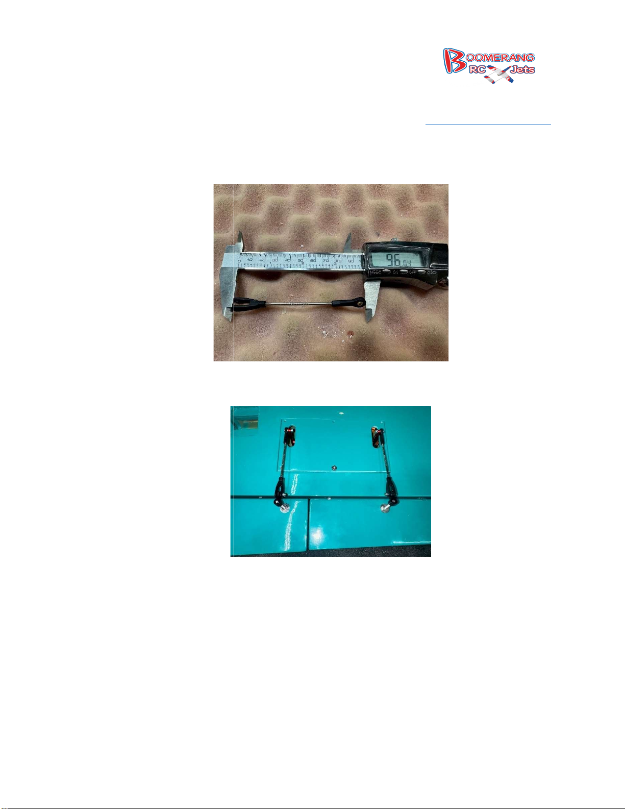
Assemble your aileron pushrods to be about 96 mm’s.
ll the pushrods and secure the hatch.
236, Middletown IN47356
www.boomerangrcjets.com
11. Insta
8768 IN-
1-765-548-3757
Page 10
12.
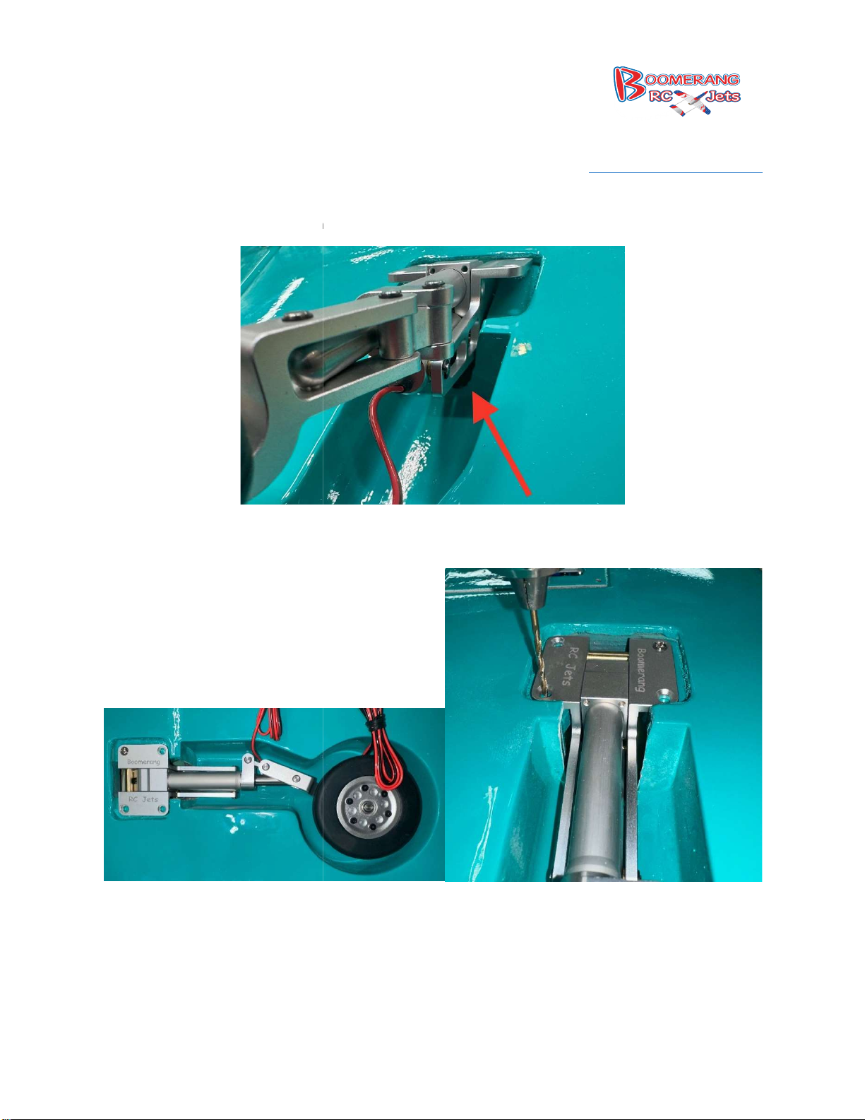
It may be necessary to trim a little bit of the fiber glass for the landing gear to drop into position.
Center the wheel in the wheel well and the mounting rails on the blocks and drill one hole at a
time to secure the landing gear.
236, Middletown IN47356
www.boomerangrcjets.com
13.
8768 IN-
1-765-548-3757
Page 11
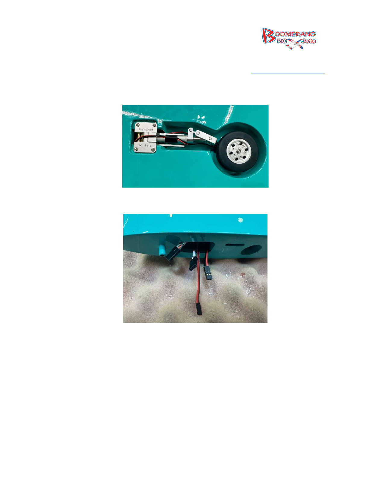
Neatly organize your wires and run them down the strut and through the wing.
Run your servo Extensions for your Flaps and Ailerons, about 16 inch
you choose to run your extensions is what is required.
236, Middletown IN47356
www.boomerangrcjets.com
extensions depending how
8768 IN-
1-765-548-3757
14.
15.
Page 12
Mounting the Wing
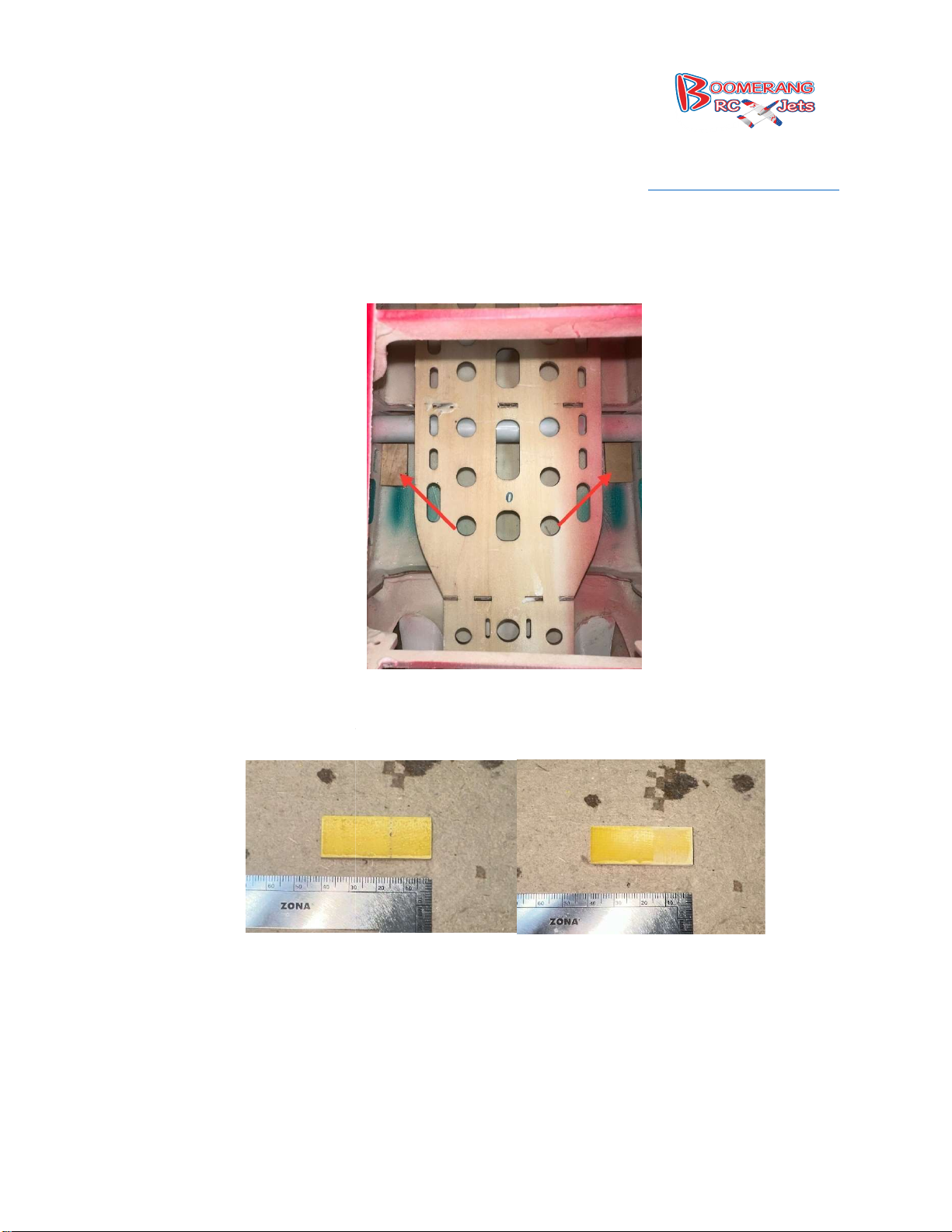
Cut 2 pieces of lite ply to be 1 inch by 1.5 inch and glue, we used 5 min Epoxy to the floor of the
fuselage, centered on the wing hold down s
Locate the fiberglass wing tabs, they will be epoxied into the wing. Measure 15 mm from one
end and draw a line. Then scuff up the fiber glass and clean off the dust, this will ensure that
the epoxy will make a good secure bond.
236, Middletown IN47356
www.boomerangrcjets.com
16.
lot.
8768 IN-
1-765-548-3757
17.
Page 13
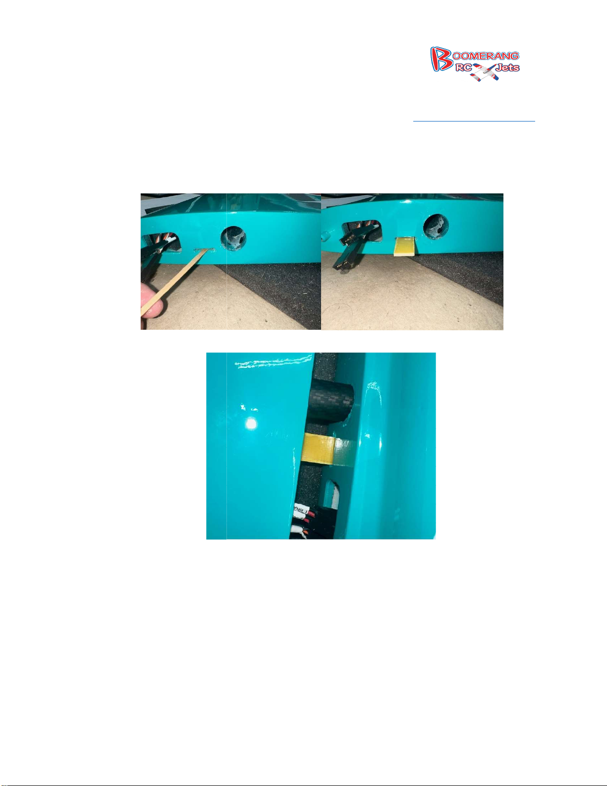
18. Test
fit the fiberglass tab into the wing, mix up the epoxy and put into the slot in the wing, then
slide the tab into it and line it up on the fuselage to hold it in place and ensure everything stays
lined up while the glue dries.
236, Middletown IN47356
www.boomerangrcjets.com
8768 IN-
1-765-548-3757
Page 14
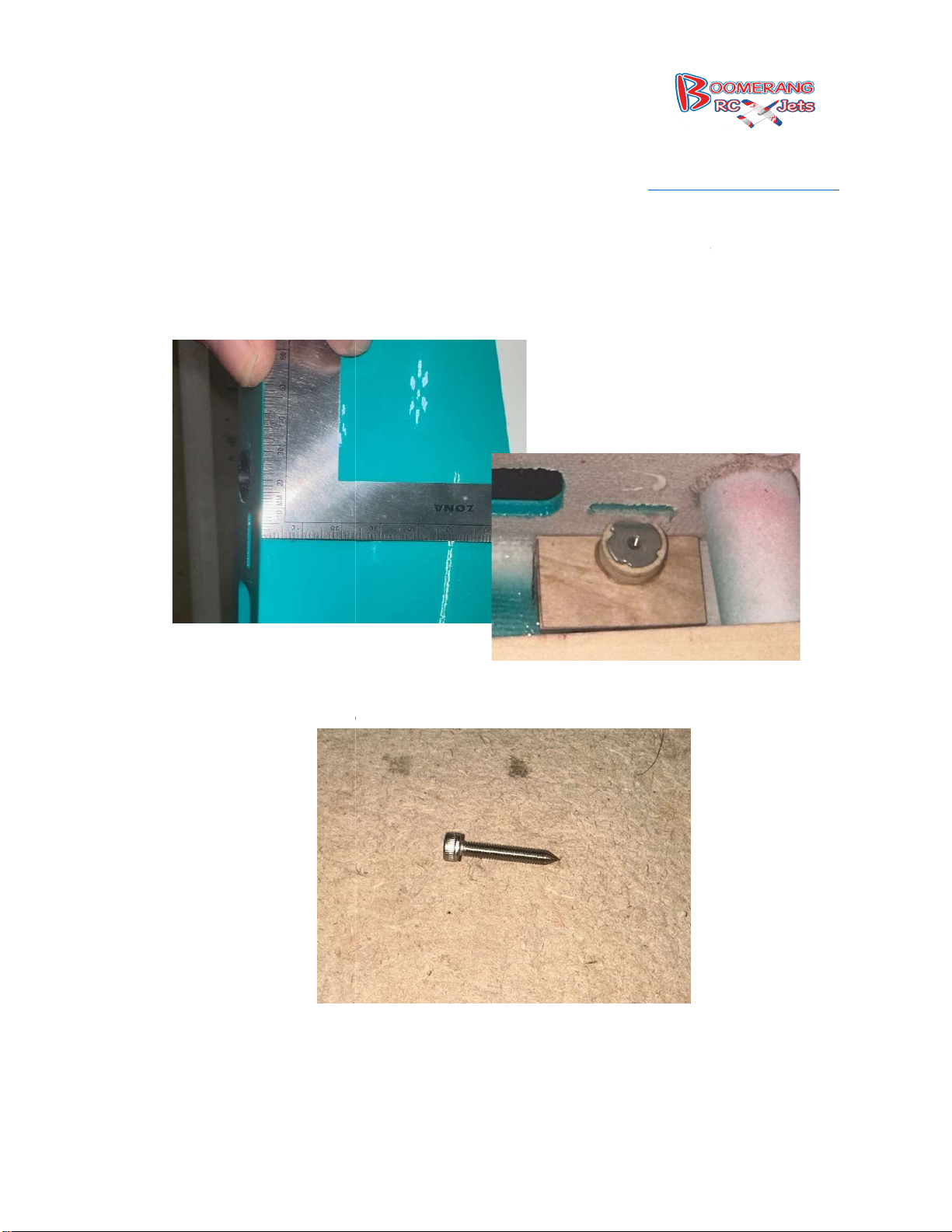
19. Flip the fuse
lage over so the belly is up. Measure to find the center of the joiner slot and then
measure in 10mm and drill your hole with a 3mm drill bit. Do this on both the left and right
side. Then glue in your blind nut on the inside on each side.
taking an extra 3mm bolt and putting a point on it we will use this to make a mark on the
fiber glass tab in the wing to show where to drill your mounting hole.
236, Middletown IN47356
www.boomerangrcjets.com
8768 IN-
1-765-548-3757
20. Then
Page 15
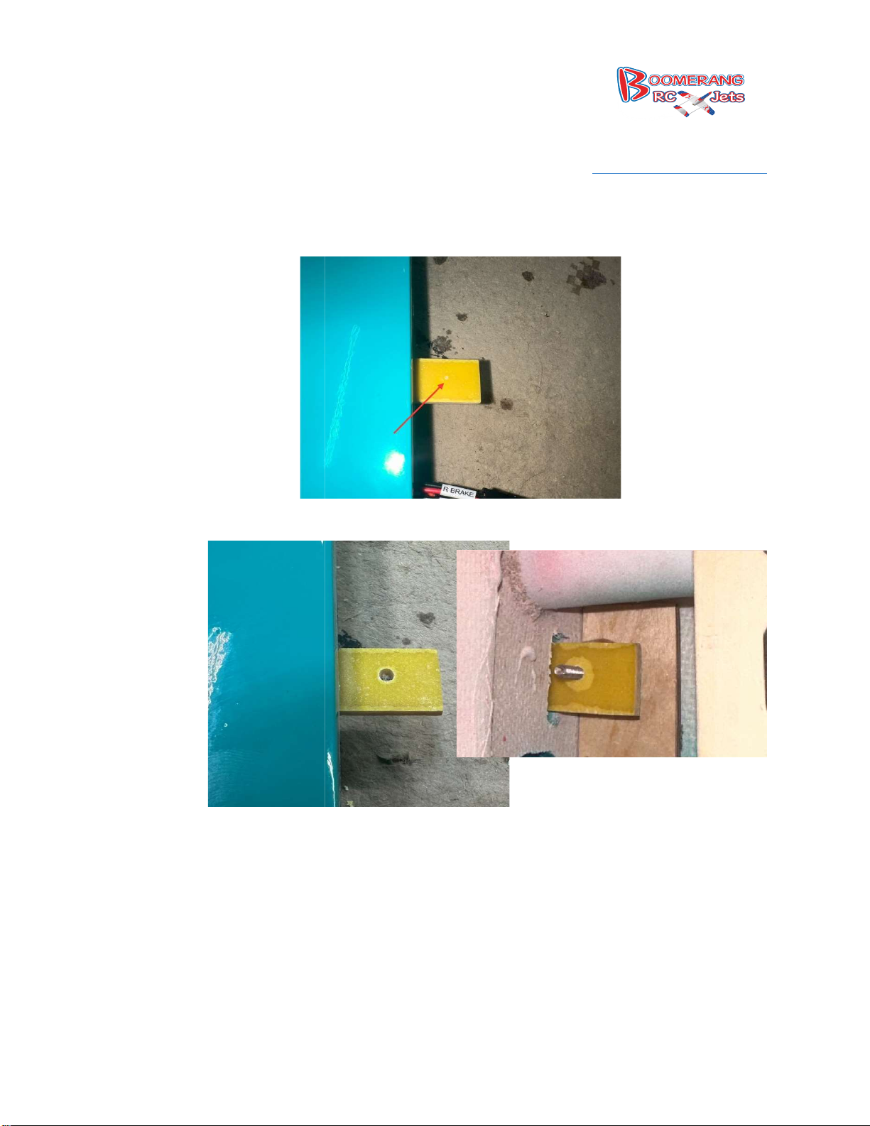
21.
Once the tab is marked use a 3 mm drill bit to drill the hole. Make sure you are
236, Middletown IN47356
www.boomerangrcjets.com
you are drilling.
8768 IN-
1-765-548-3757
square while
Page 16
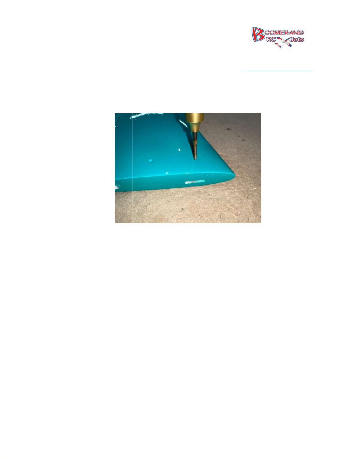
22.
Locate the threaded hole on the bottom of the stab, run a 3mm tap in and back out just to clean
out any paint that might have gotten in there.
236, Middletown IN47356
www.boomerangrcjets.com
Stabs
8768 IN-
1-765-548-3757
Page 17
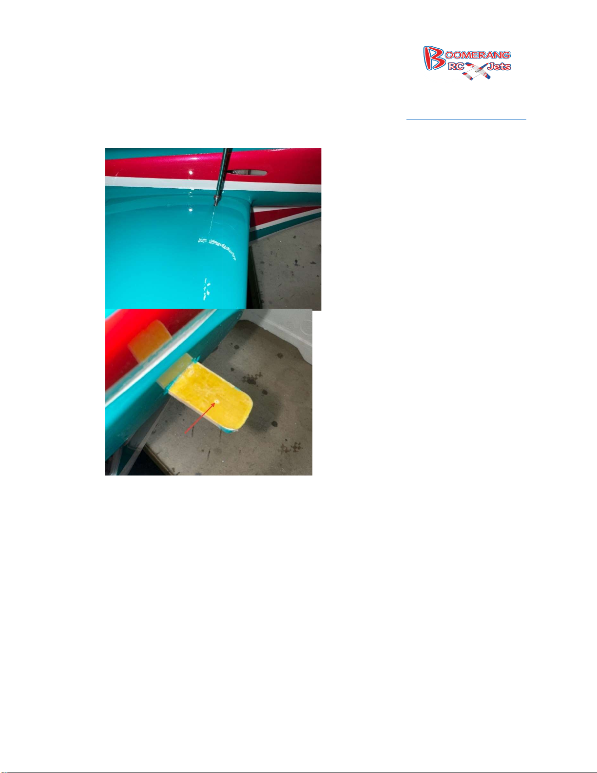
23.
Using the same pointed 3mm screw from the wing, use it to
Drill on the mark and the test fit the stab and remove.
236, Middletown IN47356
www.boomerangrcjets.com
mark fiberglass stab joiner plate.
8768 IN-
1-765-548-3757
24.
Page 18
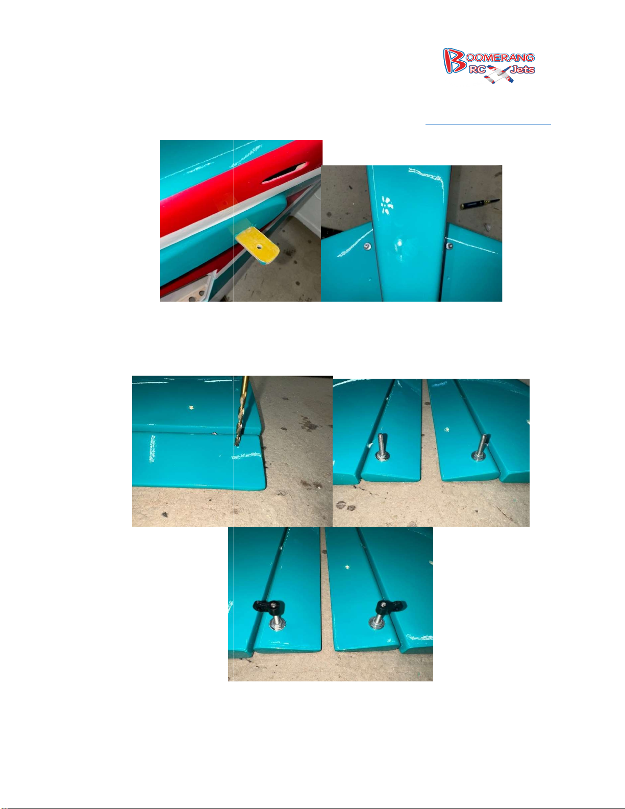
Locate the indents in the elevators and drill them out with a 3.5mm bit to allow the control
horns to pass through the elevator and install with washer
236, Middletown IN47356
www.boomerangrcjets.com
and nut, then thread on the nylon
25.
control linkage.
8768 IN-
1-765-548-3757
Page 19

26.
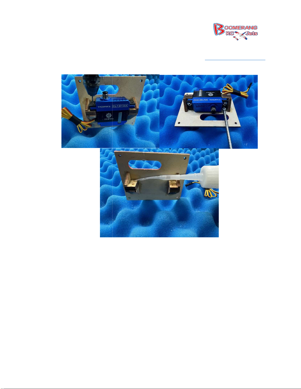
Drill the servo hatch cover screw holes using the hatch as a guide for where to drill. Then test fit
each of the four screws and put a drop of CA into each hole to harden the threads.
Depending on the servo you are using you may need to open up the block like we did here.
236, Middletown IN47356
www.boomerangrcjets.com
8768 IN-
1-765-548-3757
27.
Page 20
28.
Install the servo onto the servo plate and center the servo arm.
236, Middletown IN47356
www.boomerangrcjets.com
8768 IN-
1-765-548-3757
Page 21
29.
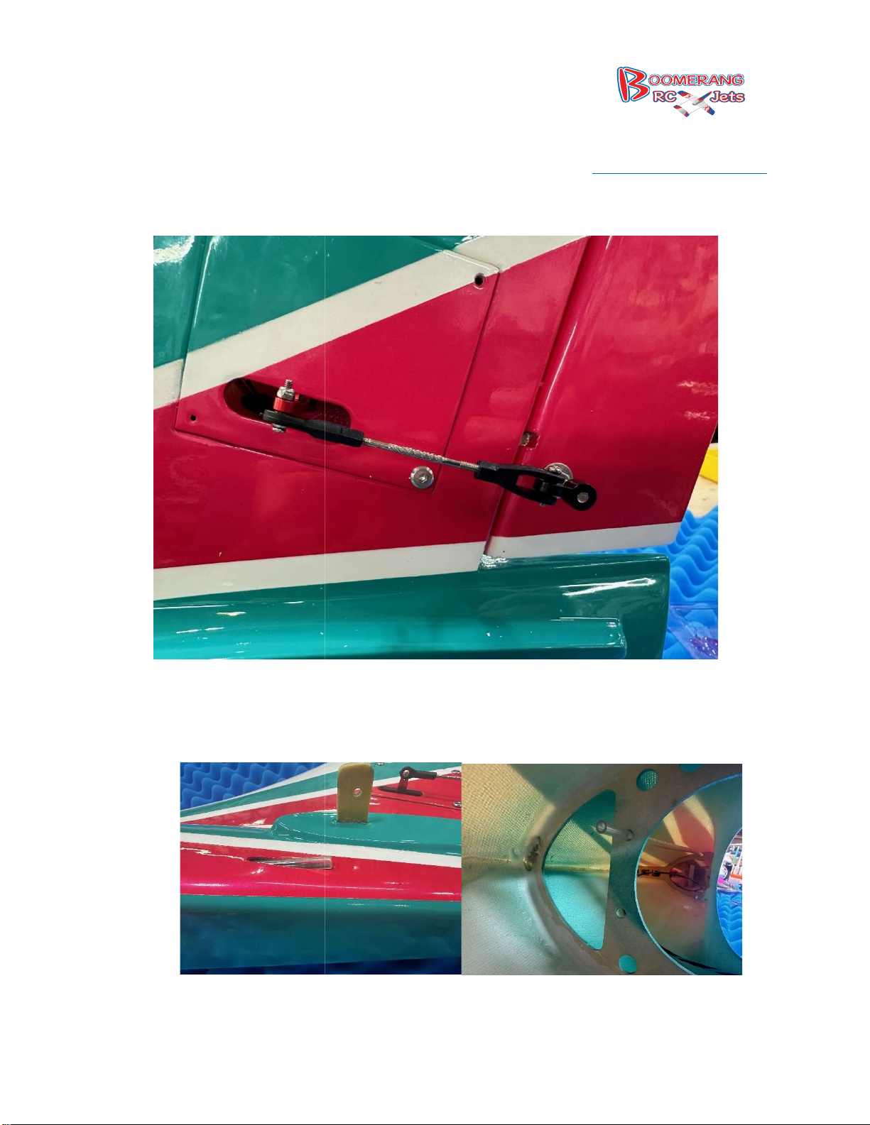
Install the nylon end of the control horn on the post, then assemble the pushrod to about 80mm
end to end. This will have to be fine tuned to your model but is a good and close starting point.
Install the pushrod guide tubes, one on each side. There ar
they go through as well as should exit just outside at the tail end. Once installed use a small
236, Middletown IN47356
www.boomerangrcjets.com
e 2 bulkheads inside the
8768 IN-
1-765-548-3757
30.
fuselage
drop of epoxy to hold them in place.
Page 22
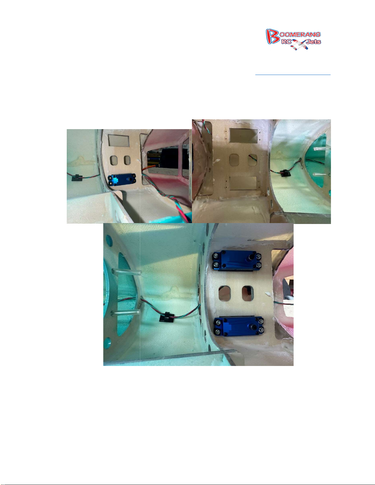
Installing the elevator servos is next. The spline will go towards the nose. In
holes for servo mounting screws. Thread the screws in and remove and put a drop of CA in each
236, Middletown IN47356
www.boomerangrcjets.com
stall the servo, drill
31.
hole and let dry.
8768 IN-
1-765-548-3757
Page 23
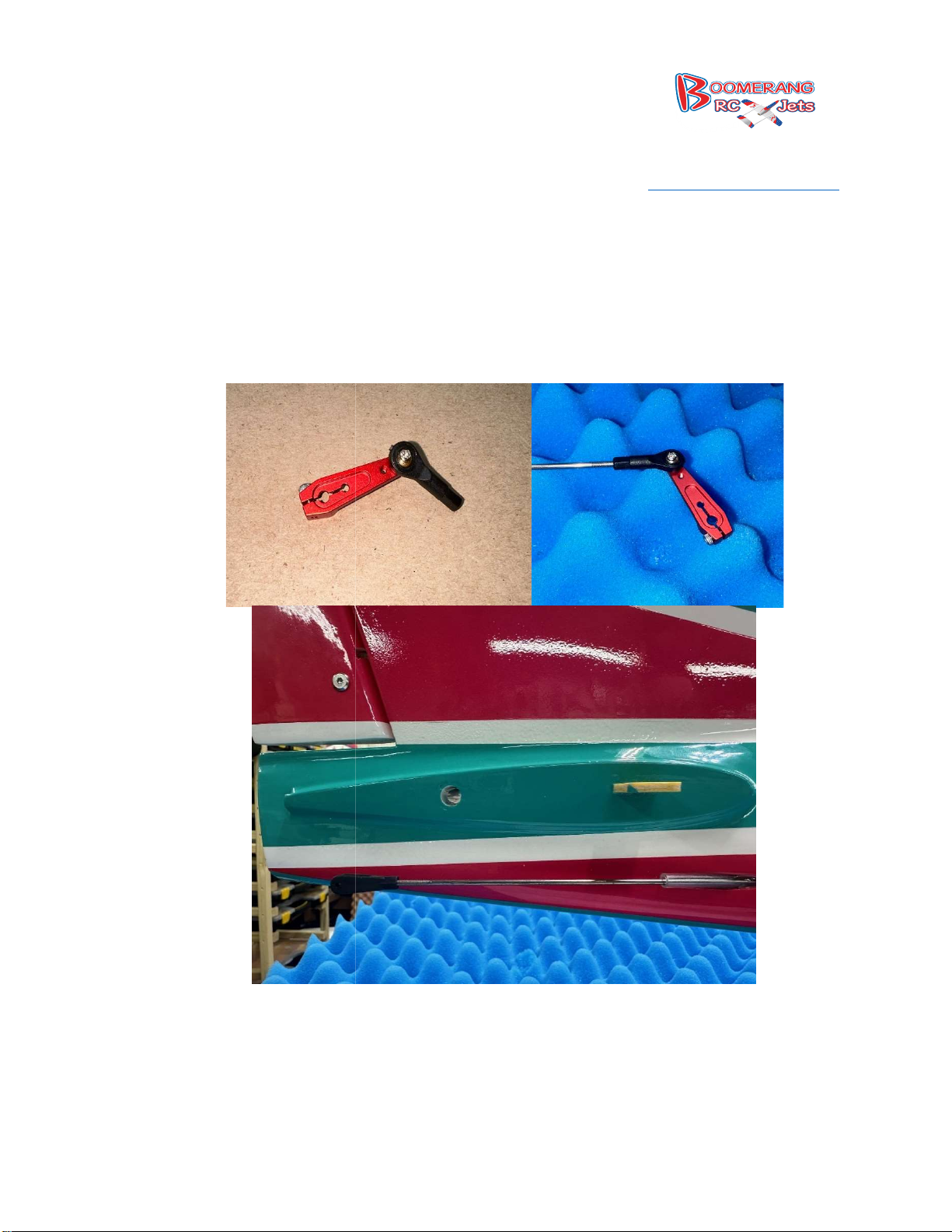
Assembling the elevator pushrods, we find it easiest to put the ball link on the servo arm and
it onto the pushrod. Then slide the pushrod in from the front of the plane and
when it exits out the back install the clevis. Then center the servos and put the arm on. It is up
to you if you want to put the stabs on now and get the elevators neutral o
236, Middletown IN47356
www.boomerangrcjets.com
r do that later. We do
8768 IN-
1-765-548-3757
32.
then putting
that later.
Page 24
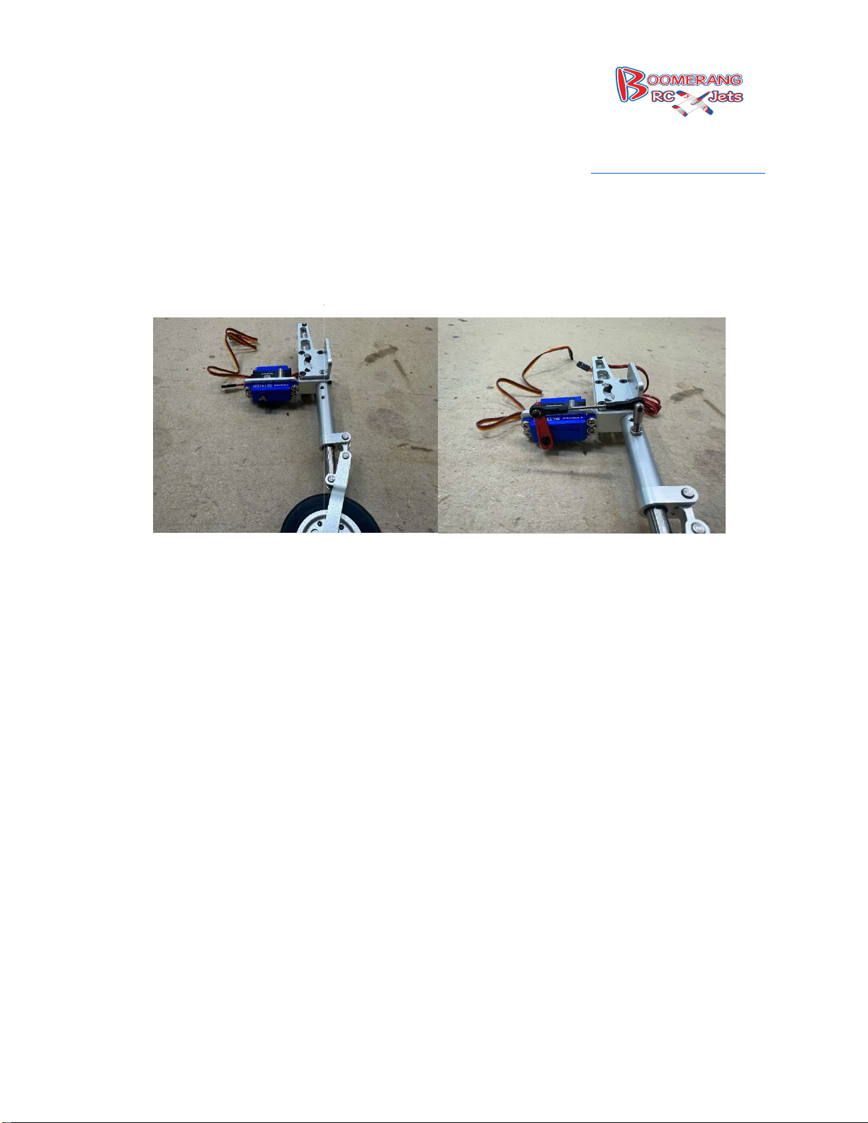
Assemble the nose steering servo onto the servo plate on the landing gear. The spline goes
away from the strut. No need for the gromets here, just directly mount the servo to the plate.
rod with standoff attached and using thread lock thread it into the nose strut
and lock in position with the lock nut. Center the servo and put the arm on the servo and adjust
the pushrod to proper length.
236, Middletown IN47356
www.boomerangrcjets.com
33.
Then find the push
8768 IN-
1-765-548-3757
Page 25
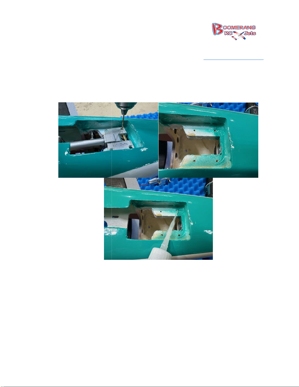
34. Installing
the nose gear, slide the retract into position and secure it on center. Then with a 2mm
drill bit drill the first of four holes, then screw in that one hole with the included wood screws.
Then carefully drill the next hole and put in the next screw, the
screw them in. Now remove the screws and put a drop of CA in each hold to harden the threads
236, Middletown IN47356
www.boomerangrcjets.com
n drill the other two holes and
in each hole.
8768 IN-
1-765-548-3757
Page 26
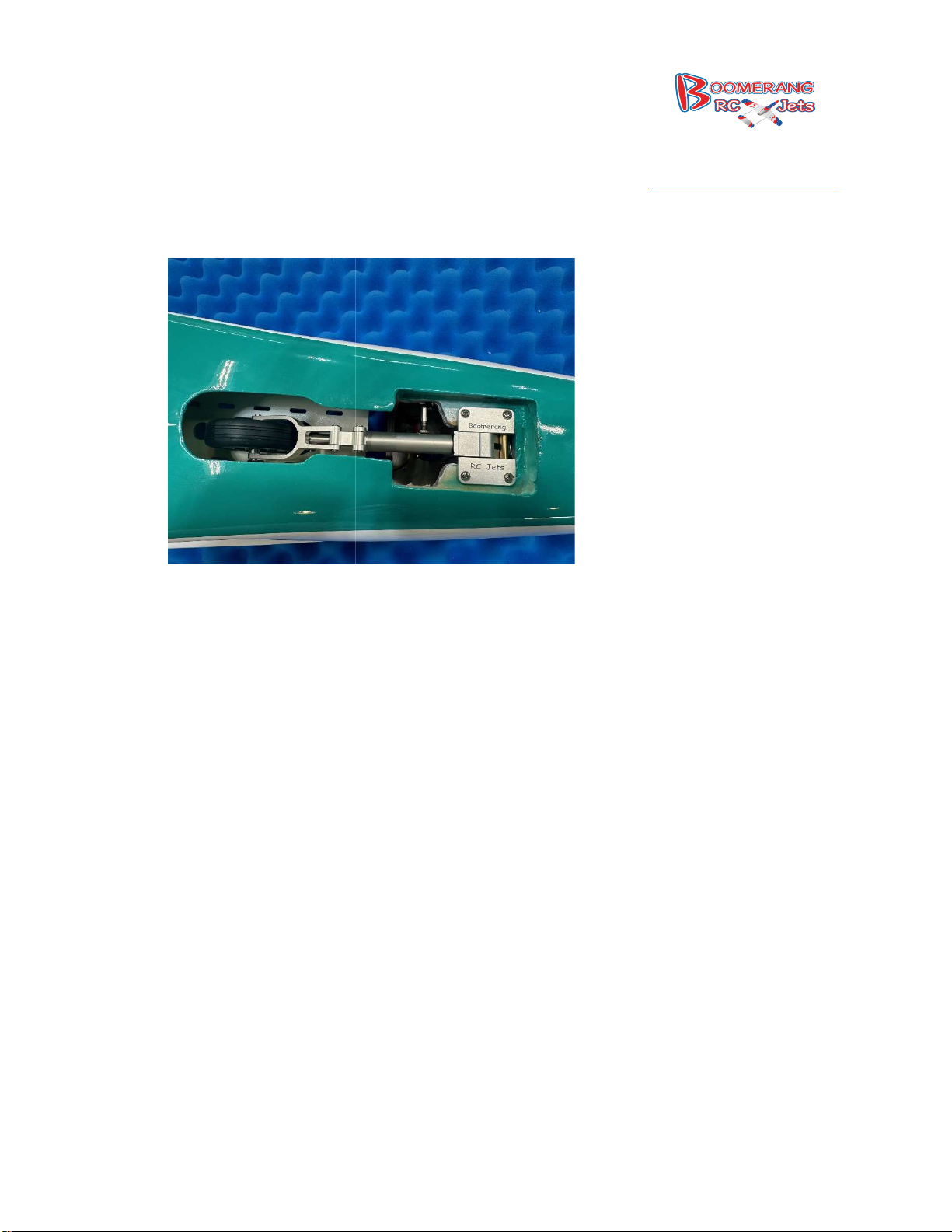
Re install the nose retract with servo and run the wires into the fuselage.
236, Middletown IN47356
www.boomerangrcjets.com
8768 IN-
1-765-548-3757
35.
Page 27
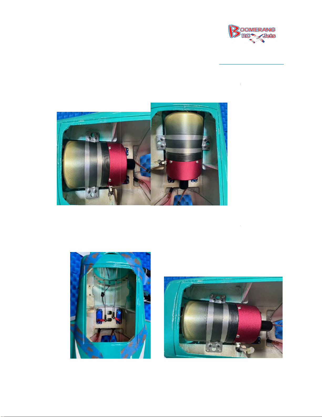
36.
Mounting the turbine is next, center the turbine between the rails, it may be necessary to trim
the rails so that everything fits. Also remember that the airplane is upside down so make sure
to mount the turbine so that its top up when the model is on its
Make sure that you have about ¼
sure the turbine is square and go ahead and drill the mounting holes for the turbine and then
using thin CA again harden the threads.
236, Middletown IN47356
www.boomerangrcjets.com
½ inch of the tail pipe on the turbine exit the fuselage. Make
8768 IN-
1-765-548-3757
wheels.
37.
-
Page 28
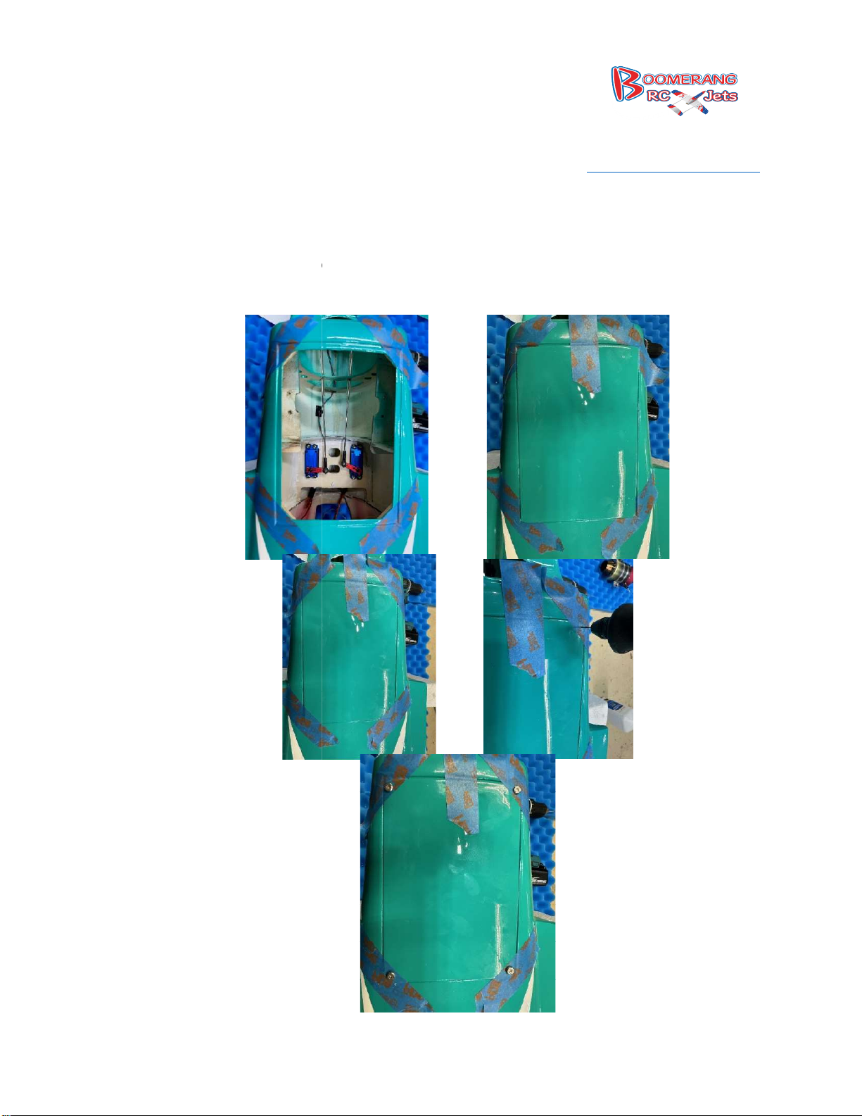
38.
A trick to make sure that when you put the hatch on and drill the holes that you don’t miss and
find the corners, take masking tape and put it across the lip. Then put the hatch into position
and put tape over the tape that you have put down that is now u
up and you will know where the edge of the lip is and can safely drill and know you will have
236, Middletown IN47356
www.boomerangrcjets.com
nder the hatch and it will line
plenty of meat when you drill.
8768 IN-
1-765-548-3757
Page 29
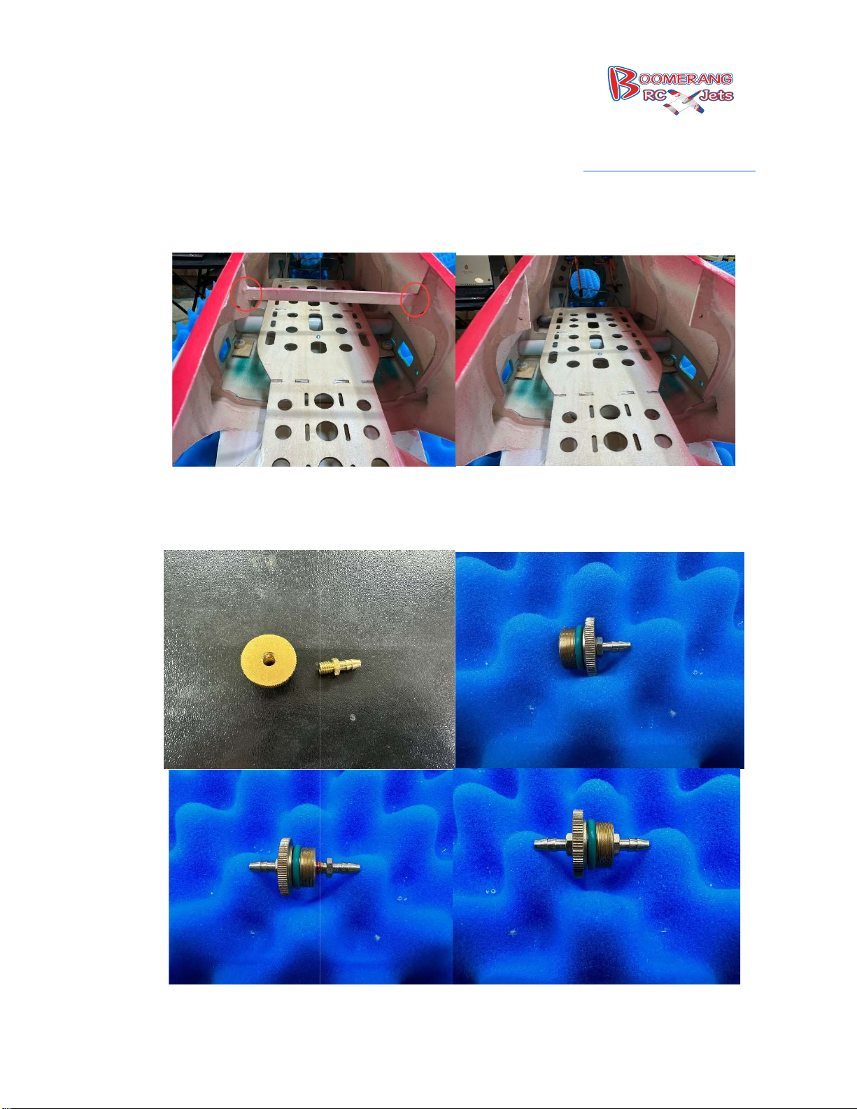
39.
To install the fuel tank, there is a cro
to remove. A small saw will work great, cut where shown below.
Onto the front of the fuel tank, the stopper is a quick assemble. The stopper has two nipples
that get screwed onto it, one on
236, Middletown IN47356
www.boomerangrcjets.com
ss brace in the fuselage when it is molded that you will need
each side. We use a drop of thread lock.
40.
8768 IN-
1-765-548-3757
Page 30
41.
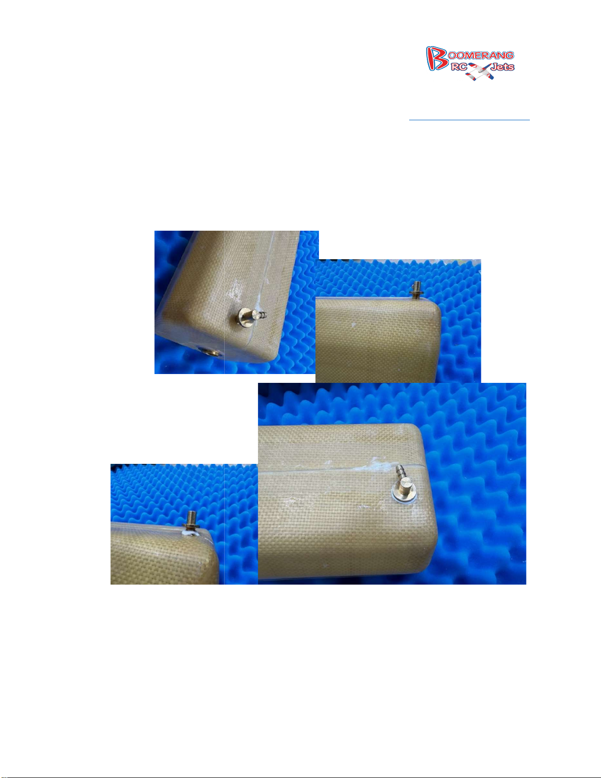
Installing the overflow into the tank requiers drilling a hole just large enough that you can start
to thread the provided overflow into. Once drilled and test fit run a bead of epoxy/ hysol under
and gently screw the overflow into the tank. Set the exit spout into a position that that it
will work with the way you are planning to run your over flow.
236, Middletown IN47356
www.boomerangrcjets.com
the lip
8768 IN-
1-765-548-3757
Page 31
42.
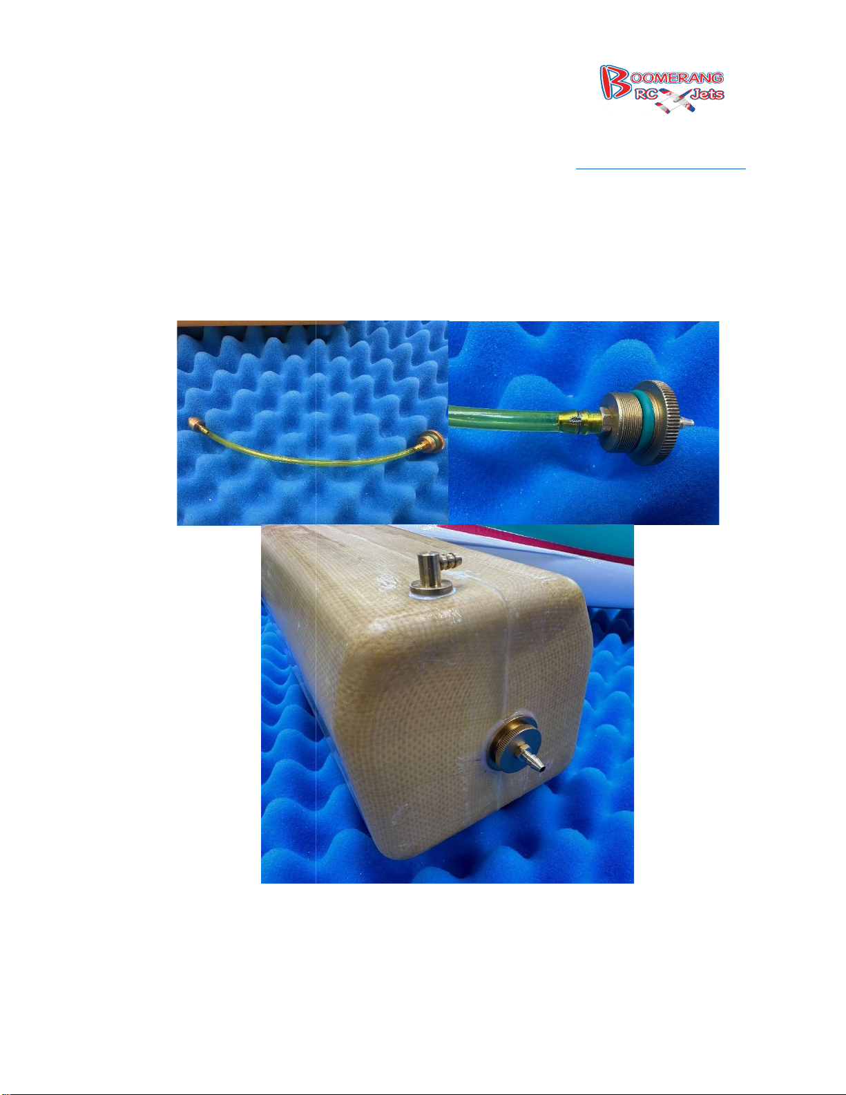
Installing the clunk, trim off a section of provided fuel tube to about 8.5 inches and put it on the
nipple on the inside of the stopper and the fuel clunk. Once on and in place test fit it into the
fuel tank to ensure its not rubbing on the back of the t
safety wire the connections on to ensure they will not separate and then screw the stopper into
236, Middletown IN47356
www.boomerangrcjets.com
hank. If everything is good, go ahead and
the front of the tank.
8768 IN-
1-765-548-3757
Page 32
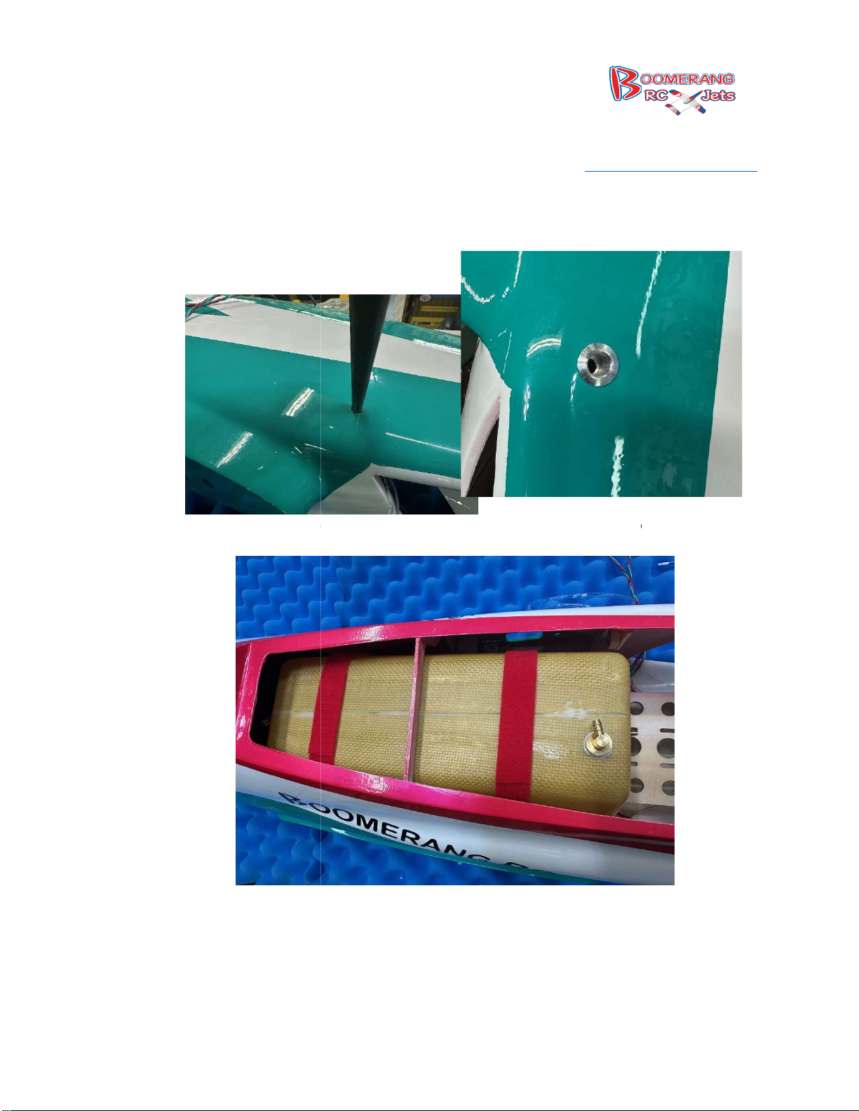
43. Now you will need to de
cide where you want to mount the overflow and drill for that to the
proper size of the overflow you will be using.
Install the fuel tank and secure with Velcro straps and screw the included front cross brace in
236, Middletown IN47356
www.boomerangrcjets.com
44.
8768 IN-
place.
1-765-548-3757
Page 33
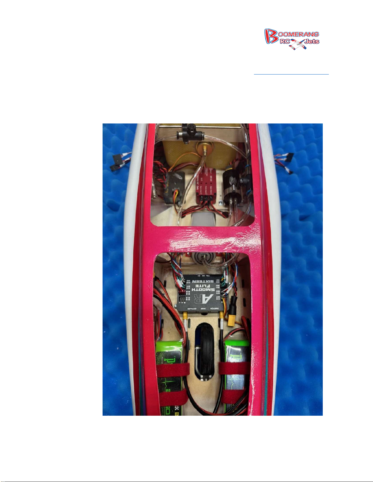
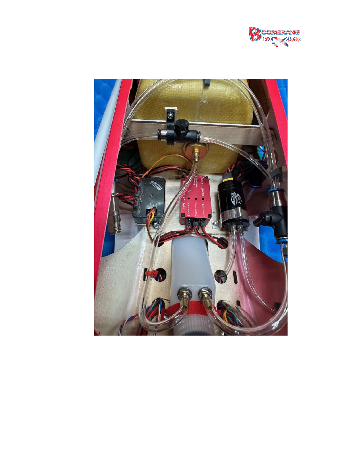
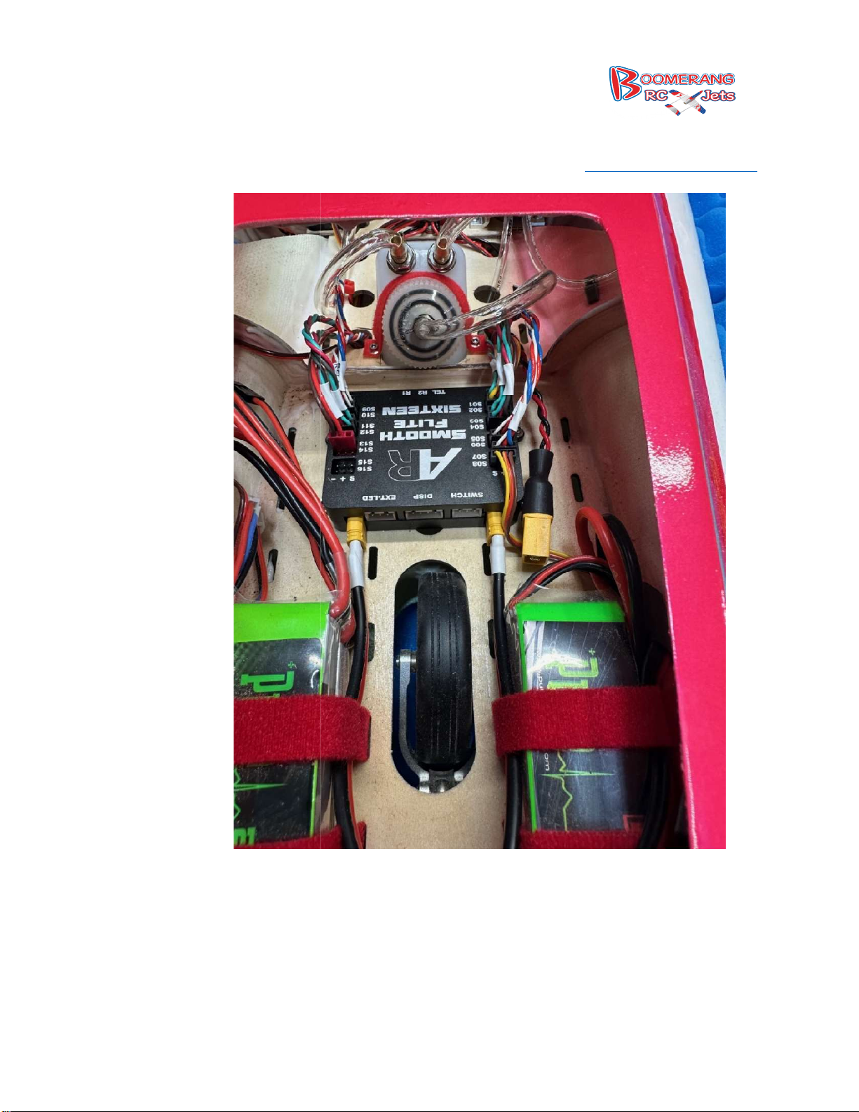
45. Now is to install all of
your components, UAT, Gyro, ECU, Batteries, Gear controller and receiver
along with your fuel lines. Please refer to the pictures below for how we did it using our
equipment, please feel free to set it up any.
236, Middletown IN47356
www.boomerangrcjets.com
8768 IN-
1-765-548-3757
Page 34
8768 IN-
236, Middletown IN47356
www.boomerangrcjets.com
1-765-548-3757
Page 35
8768 IN-
236, Middletown IN47356
www.boomerangrcjets.com
1-765-548-3757
Page 36
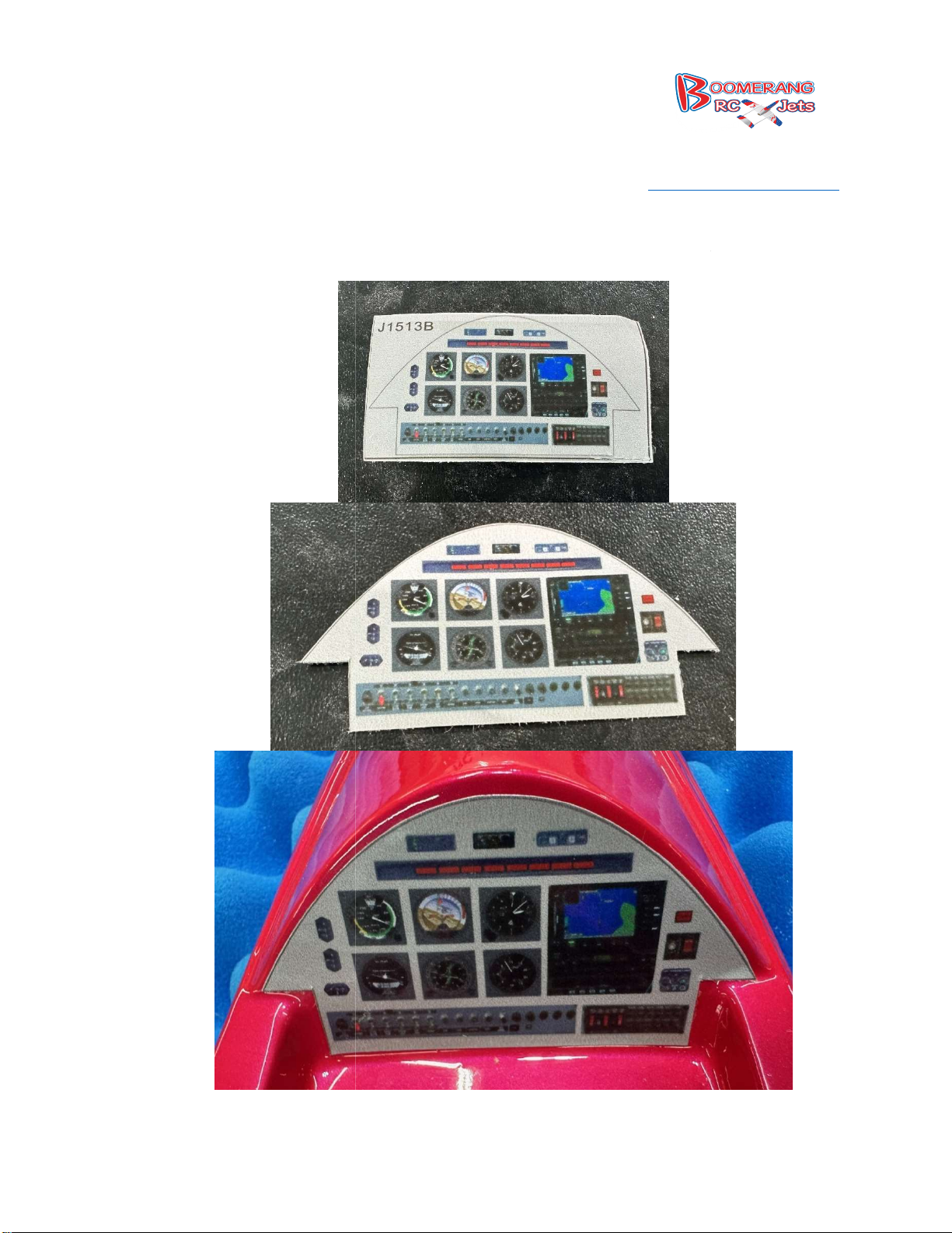
46.
Finally cut the instrument panel
perfect fit and secure the canopy with either screws or glue. If you want to install a pilot now is
236, Middletown IN47356
www.boomerangrcjets.com
out and install it in the cockpit, trim the canopy to ensure the
the time to do it.
8768 IN-
1-765-548-3757
Page 37

20 degrees up and down
10 Degrees up and 13 down
20 Degrees up and down
15 Degrees up and down
14 Degrees
20 Degrees up and down
20 Degrees up and 10 Degrees down
50 Degrees Down with 7.5 Degree down Elevator Mix
5 Degree up Ailerons
CG measured from Leading edge at Root:
Using the Sky RC CG device these are the settings to use:
Distance Between CG and Main Wheel Centerline:
Distance from mains to the weight placement point:
236, Middletown IN47356
www.boomerangrcjets.com
8768 IN-
1-765-548-3757
Lancer Flight Mode Rates
Normal Flight
Ailerons:
Elevator:
Rudder: Max
Take off Flap setting
Ailerons:
Elevator:
Rudder: Max
Flaps:
Landing Flaps Settings:
Ailerons:
Elevator:
Rudder: Max
Full Flaps:
Crow:
down with 1.5 Degree down Elevator Mix
Wheelbase:
Correction Point:
Lancer CG Settings
163mm
660mm
64mm
660mm
Nose
Page 38

236, Middletown IN47356
www.boomerangrcjets.com
8768 IN-
1-765-548-3757
 Loading...