

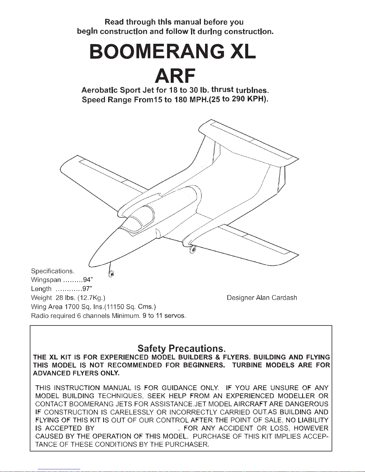
Boomerang RC Jets, LLC.
Website www.Boomerang-RC-Jets.com
Boomerang RC Jets, LLC.
2
Some of the additional items required to complete this kit:-
Extension leads to servos
2 X 1.5 metres (along booms to elevators)
8 X 1 metre from RX to outlet ribs of centre wing
2 X 1 metre along booms to rudders
2 X 300 mm from ailerons in outer wings
2 X 100 mm. from flaps in outer wings
1 X 300mm for steering servo
1 set heavy duty retracts, (Boomerang Jets option available)
1 set of wheels and brakes, (Boomerang Jets option available)
1 set wire legs, (5/6mm) or oleos (Boomerang Jets option available)
1 X electronic air valve for retracts,
1 X electronic air valve for brakes,
8 servos for control surfaces (5 to 8K torque digitals suggested)
1 servo for nose leg steering.
Many modellers prefer to choose commercially available control
horns, so these are not included in the kit. Optional Boomerang
Jets custom pushrod/clevis/ horns pack is available.
A
B
2mm
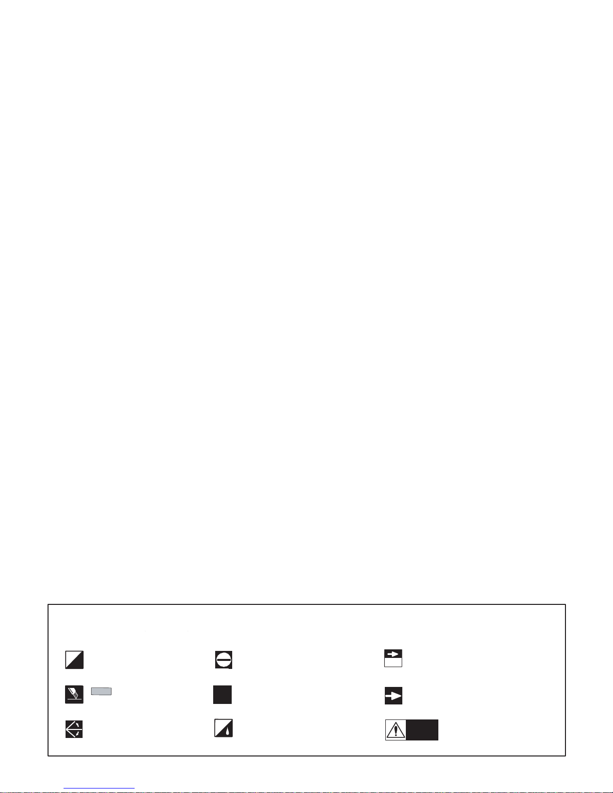
Warning!
Note the Symbols used throughout these
L
R
Assemble left and right sides
the same way.
Not supplied
Drill holes to the specified
diameter (here: 2mm. shown).
Cut off shaded portion.
Apply epoxy glue.
Pay close attention here!
Ensure smooth non-binding
movement while assembling.
Apply instant glue (CA glue, super glue).
Do not overlook this symbol!
3
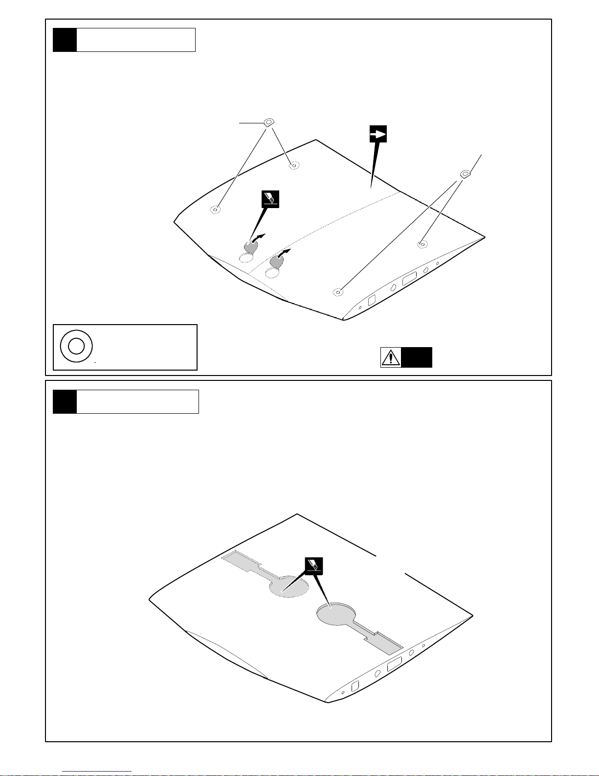
2
Centre Wing Underside
Iron the main landing gear area lightly through a cloth with a warm
iron before cutting away the covering film.
Take care not to damage the painted surfaces.
Cut away covering film.
For Main Landing Gear
Self-adhesive
4
1
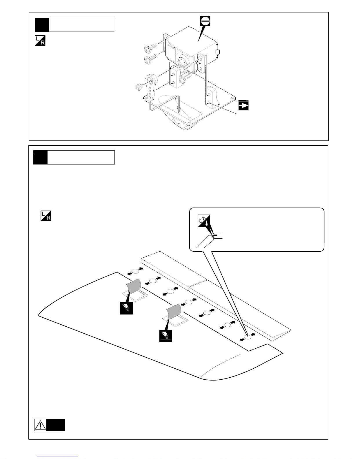
Centre Wing Topside
Iron the area lightly through a cloth with a warm
iron before cutting away the covering film from the exit
Self-adhesive
Wing Top
Self-adhesive
Cut away covering film.
Warning!
Be sure to glue securely.
This is Vital for safe flying!
4
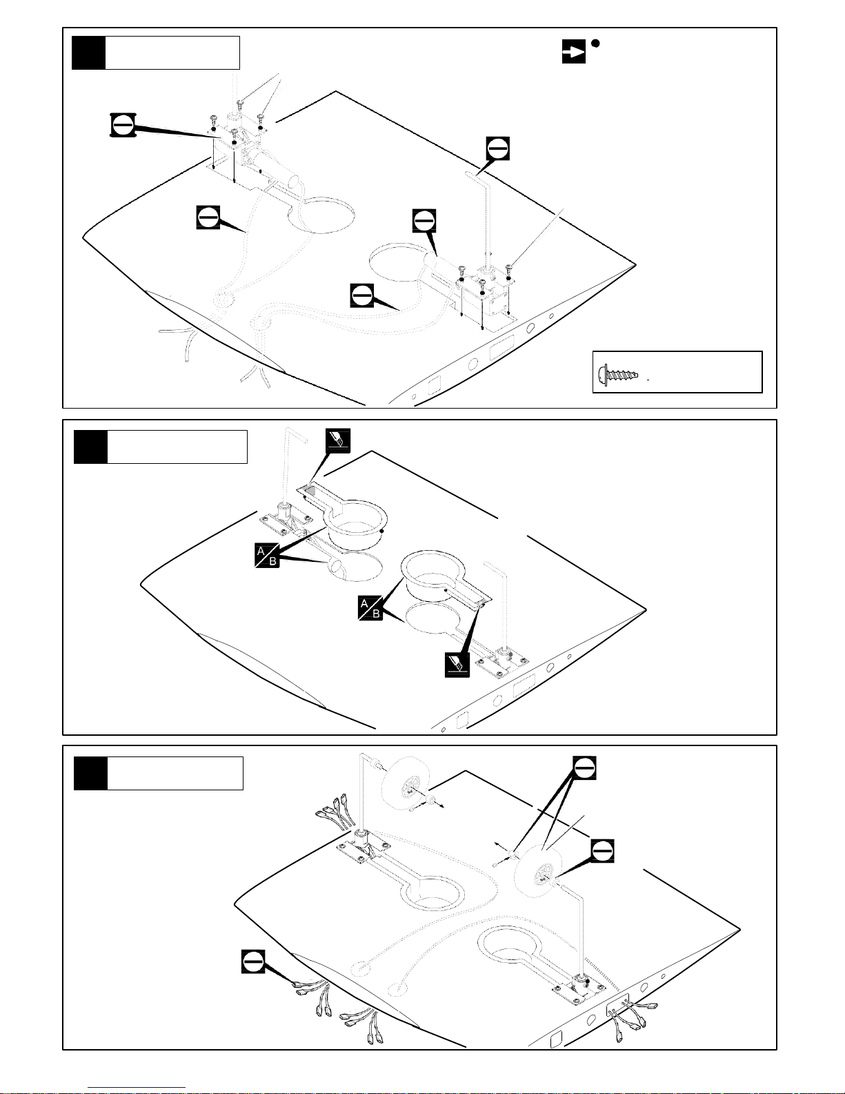
5
Mounting Retracts
Not Supplied.
Up to 2.75 inches
Not Supplied.
Not Supplied.
4
Cut off shaded portion.
Wheel Wells
Pass all 8 servo wires and air lines through the
centre wing before you trim the whe.el wells to
fit. Do not fix the vacformed wheel wells u.ntil
the servo wires and air lines are all in
place.Then trim the wheel wells to fit leaving
approx. 3mm.flat surface on top and fit and glue
them under the balsa wing surface.
NOTE;
Do not fix plastic wheel wells until the
servo wires and air lines are in place.
Cut off shaded portion.
2.6 x12mm TP Screw
8
3
Requires some modification
Main Retracts
2.6 x12mm
TP Screw
on main gear cover.
.
Not Supplied.
Not Supplied.
Not Supplied.
2.6 x12mm
TP Screw
Not Supplied.
5
7
Wings
Lightly iron the covering film through a cloth and cut away allowing 3 mm overhang all
round.
Assemble left and right sides
the same wa.y
Be sure to apply instant type CA glue to
both sides of each hinges.
(low viscosity type)
Cut away covering film.
Cut away covering film.
Warning!
Be sure to glue securely
This is Vital for safe flying!
6
Servo Mounts
Assemble left and right sides
the same wa.y
Position of holes may need
adjustment depending on
servo brand used

6
2.6 x 12mm
TP Screw
8
2.6 x 12mm
TP Screw
8
9
Servo Mounts
Note: - Both flap servos are the same hand to ensure identical movement.
Allow 120 mm (5”) overhang of servo leads.
2.6 x12mm TP Screw
Extension lead
300 mm from ailerons in outer wings
Not Supplied.
Not Supplied.
Not Supplied.
Not Supplied.
Not Supplied.
Extension lead
100 mm. from flaps in outer
8
Servo Mounts
Fix servos using servo mounts supplied.
2.6 x12mm TP Screw
Not Supplied.
Not Supplied.
Not Supplied.

7
2.6 x12mm TP Screw
8
11
Rudder Servo
Extension lead
1 metre along booms to rudders
2.6 x12mm TP Screw
10
Alloy dowels
9x285mm
9x285mm
Screw in the 9 X 285 mm alloy dowels.
Ensure at least 120 mm (5”) servo wire minimum overhang
(to pass through the booms when field assembling)

8
13
Tailplane/Stab
Lightly iron covering through a cloth with warm
iron before cutting away covering film,
(leaving 3 mm. overhang all round the servo mounts as per the
Be sure to apply
instant
type CA glue to both
sides of each hinges.
Cut away covering film.
12
Rudders
Assemble left and right sides
the same way.
Use thin cyano both sides of each hinge
not supplied
3mm. or 4/40 pushrod and
clevises (not supplied).
not supplied
Assemble left and right sides
the same way.

Not Supplied
Right boom shown.
Heat Gun Be careflul not to
scorch the
heat-shr1n
J)I
W)n
·
k Tube
2m x 40mm
Heat-shrink Tube

10
Self adhesive
4
3 x 30mm Bolt
4
17 Tail Assembly
Self adhesive
3 x 30mm Bolt
3 x 30mm Bolt
Decrease size of top
exit hole after wires
are through to prevent
the connector falling
inside the fin.
16
Wing Locking
Lock
Wing Top
2.5mm Hex Wrench
3x6mm Bolt
3x6mm Bolt
3 x 6mm Bolt
4

4mm Washer
2
4mm Lock Nut
2
4 x 15mm Screw
2
11
19
Nose gear
55mm
Not Supplied.
Not Supplied.
“Trim the Cover Plate to clear the leg.”
“Use plywood to pack up the retract
mount as necessary to clear the
bearers when retracted.”
Not Supplied.
Not Supplied.
3mm
18
Additional safety fitting to stabilisor
With tailplane (Stab.) firmly
screwed down, pass a 3.6mm
drill through the holes in the fins
and drill a hole through the metal
tongue projecting down from the
Stab. Remove the Stab and tap
the new hole in the tongue out to
4mm thread. Repeat the
process through the other fin.
During assembly apply the 4mm
X15mm bolt through the fins and
the tongues and lock in place
with the 4mm nylock nuts and
washers supplied. If a 4mm tap
is not available drill the hole in
the tongue out to 4mm and
assemble the same way.

12
21
Gluing fuselage to wing
20

Check belly pan for fit, mark, then lightly iron covering,
then cut away wing covering as you did with the fuselage,
to expose Balsa. Glue in place."
/
Fuel Tank etc
Suggested Fuel Tank 3 litre pop bottle
The tank mounting formers can be cut
away to accommodate a larger tank
if required.
Cockpit Canopy
"Cut away a section of the cockpit floor to
allow the vacuum formed seat unit to be
glued or screwed in place. Add fascia
decal. Add pilot (not supplied}. Mark
and drill canopy and screw in pl ace."
13
2.6 x12mm TP Screw
------------------------ 10

"Trim hatch latch and if necessary adjust the 6mm.
dowels to achieve a good fit."
4mm Blind Nut
---------------------------- 1
4mm Washer
-- ---- - ----------------------· 1
lf
necessary, the use of large nicad packs will give the correct
CG for the first trimming flights CG should be as shown. Later
you can move the CG back a small amount at a time to
increase sensitivity for aerobatics. Set the travel to the values
shown below for the first flight. You can increase these later for
aerobatics if desired. Mount the control horns so that the
hole for the clevis is at 5 mm. behind the hinge on ailerons (to
provide differential). 1Omm. behind the low hinge line for the
flaps (to maximise movement), and Close to the hinge line
for the rudders and elevators."
Set the travel to the values show below
for the first flights. You can increase
these later for aerobatics if desired.
Carefully install the receiver and
battery
pack to
ensure that they will not shift during flight.
Shift the location of the receiver and battery pack
as
needed to obtain the specified CG.
ELEVATOR
.-- 30mm
_,.,- 40mm
----::;:;
;.:-- -<-- t---- Omm
.::::_:oJ
----, 30mm
Maximum possible down.
FLAP
For
first
trimming flights CG should be as shown.
Later you can move the CG back a small amount
at a time to increase sensitivity for aerobatics.
220 mm from Leading edge
350 mm from Trailing edge
14
AILERON
RUDDER
e
@
CG

The Boomerang XL is capable of just about any
maneuver possible with a jet. Take off run even on grass
is about ten yards if desired, and landing similarly short.
All development and most testing was done flying from
a 75 yard square grass surfaced flying field, ensuring
that the concept of a low maintenance, low stress, easy to
fly jet model was achieved. You will find that there is
almost no trim change when using the flaps. The
original XL models all used crow braking. If you have a
suitable computer transmitter, have the ailerons on two
separate channels and the flaps on a single channel
using a Y lead. Mix the flap and aileron channels so that
from half flap onwards the ailerons both rise together
until at full flap deflection of between 80 and 90 degrees
down, both ailerons are approximately 25 degrees
deflected up. This will still allow good lateral control and
will allow amazing slow flight on about one third to a half
throttle with the nose high, including a virtually stationary
hover on a breezy day.

IMPORTANT WARNING.
READ THROUGH BEFORE ASSEMBLING OR FLYING YOUR KIT.
Just as in any full size aircraft, any RIC model aircraft can be made to fail, be
it
a wing folding or a fuselage breaking under too high a load. Model RIC aircraft have a maximum safe G limit. Because you are
not in the plane
it
is difficult to judge the G during flight, and it is very easy to exceed the limits of the
aircraft. This is particularly important
if
you install a turbine larger or more powerful than the power band
specified for that particular kit. This negates any airframe warranty straight away.
All our designs are thoroughly test flown before the kit is released for sale. Turbine powered RIC model
aircraft are not manufactured to withstand unlimited G forces. When flying your Boomerang Jet, be
aware of the high loads which can be in excess of the airframes capability to handle. Respect the
airframe as you would when flying a full size aircraft. Fit a turbine only up to the specified power.
Understand that if you perform a snap roll, wall, blender, knife edge loop or any similar maneuver, or
pull hard on the elevator, particularly at high speed, you can over stress the airframe by up to15 G or
more. At 15 G, the 27 lbs (12.2 Kilo) model effectively weighs over 400 lbs (184 kilo), and though it may
be for only a few seconds, the strain on the airframe is huge. Your model may survive those hard
maneuvers a few times, but eventually the cumulative damage will tell and airframe break up can
occur.
It is common practice for any manufacturer not to replace an airframe which breaks in the air or upon
landing. Manufacturers may replace airframes when they have noticed many incidences of the same
failure and it is determined that there was a design fault or repeated manufacturing error. If you break
an airframe, and you are the only one to do so, then it is highly unlikely to be the fault of the manufacturer. Fly safely, and avoid full throttle operation other than at low airspeeds.
RIC model jets are not toys! If misused, they can cause serious bodily harm and property damage. Fly
only in open areas, and AMA (Academy of Model Aeronautics) or BMFA (British Model Flying Association) or your country's approved flying sites. Follow all manufacturer instructions included with your
plane, radio, servo's, batteries and engine. Each kit is guaranteed to be free from defects in both material and workmanship at the date of purchase. Warranty does not cover any component assembled by
the customer. All parts of high stress must be inspected and reinforced if necessary by a competent
builder.
Some parts should be examined, and if necessary, glued again. High stress areas such as firewalls,
motor mounts, wing mounts, landing gear mounts, etc., are areas of high concern. Seek help if necessary.
In no case shall Boomerang RC Jets, LLC. warranty cover any product which is not manufactured
by Boomerang RC Jets, LLC. The liability to the manufacturer cannot exceed the original cost of
the purchased item.
Further, Boomerang RC Jets, LLC. reserves the right to change or modify this warranty without
notice. In that Boomerang RC Jets, LLC. has no control over the assembly or materials used by the
builder of the model during final assembly, no liability shall be assumed nor accepted for any
damage resulting from the use of the final user-assembled product. By using the user assembled
product, the user accepts all resulting liability. The kits manufacturers have provided you with a top
quality, thoroughly tested kit and instructions, but ultimately the quality and flying ability of your finished
model depends on how you build it. Therefore, we cannot in any way guarantee the performance
of your completed model, and no representations are expressed or implied as to the performance or
safety of your completed model. It is the user’s responsibility to inspect each component for
airworthiness.
 Loading...