

Page 1

User Manual
For SD Series
Smart & Accurate
Page 2

1
BONMET motion GmbH/www.bonmet.com/www.bonmet.de
Preface
Thank you for choosing BONMET‘s DC servo products.
This manual is a user guide that provides the information on how to install, operate and maintain
SD series DC servo drive. The contents of this manual include the following topics:
● Installation of DC servo drives and motors
● Configuration and wiring
● Trial run steps
● Control functions and adjusting methods of DC servo drives
● Parameter settings
● Inspection and maintenance
● Troubleshooting
● Application examples
Before using the product, please read this manual to ensure correct use. Users should thoroughly
understand all safety precautions (DANGERS and WARNINGS) before proceeding with the
installation, wiring and operation. If you still have any problem, please contact with the local
Bonmet sales representative. Place this user manual in a safe location for future reference.
Page 3
2
BONMET motion GmbH/www.bonmet.com/www.bonmet.de
Safety Precautions
● To prevent electric shock, note the following:
DANGEROUS
· Before wiring or inspection, switch power off and wait for more than 10 minutes. Then,
confirm the voltage is safe with voltage tester. Otherwise, you may get an electric shock.
· Wiring must be carried by electrical engineer.
· Connect the servo drive and servo motor to ground.
· Operate the switches with dry hand to prevent an electric shock.
· The cables should not be damaged, stressed, loaded, or pinched. Otherwise, you may get an
electric shock.
● To prevent fire, note the following:
CAUTION
· Do not install the servo drive, servo motor and regenerative brake resistor on or near
combustibles. Otherwise a fire may cause.
· When the servo drive has become faulty, switch off the main power. Continuous flow of a
large current may cause a fire.
· When there is a signal faulty as a regenerative brake resistor is used, please switch the main
power off. Otherwise, a regenerative brake transistor fault may overheat the regenerative
brake resistor and cause a fire.
● Wiring Precautions
CAUTION
· Wire the equipment correctly and securely.
· Connect the output terminals (U, V, W) correctly.
· Do not connect AC power directly to the servo motor or servo drive.
● Operation and Adjustment Precautions
CAUTION
· Do not touch the radiator and the regenerative brake resistor as they are overheated.
· Do not set parameter value unduly. If so, system would be instable.
· Do not touch the rotating parts of the servo motor in operation. Doing so may cause injury.
● Others
CAUTION
· Do not attempt to remold the servo drive.
Page 4

3
BONMET motion GmbH/www.bonmet.com/www.bonmet.de
CONTENTS
Chapter 1
• • • • • •
Model and Specifications
Chapter 2
• • • • • •
Installation
Chapter 3
• • • • • •
Wiring
Chapter 4
• • • • • •
Display and Operation
Chapter 5
• • • • • •
Operation
Chapter 6
• • • • • •
Parameters
Chapter 7
• • • • • •
Communication
Chapter 8
• • • • • •
Protective Functions
Page 5
4
BONMET motion GmbH/www.bonmet.com/www.bonmet.de
Chapter 1 Model and Specifications
1.1 Unpacking Check
After receiving the DC servo drive, please check for the followings in order to prevent mistake during purchase or
shipment:
● Check the following section about the model explanation of the servo drive and motor to ensure that the
product is what you have ordered.
● Rotate the motor shaft slightly by hand, a smooth rotation will indicate a good motor. However, a servo
motor with holding brake can not be rotated manually unless give power to the holding brake to release
the shaft.
● Inspect the unit to insure it was not damaged during shipment.
If any items are damaged or incorrect, please inform the distributor whom you purchased the product from or your
local BONMET sales representative.
1.2 Model Explanation
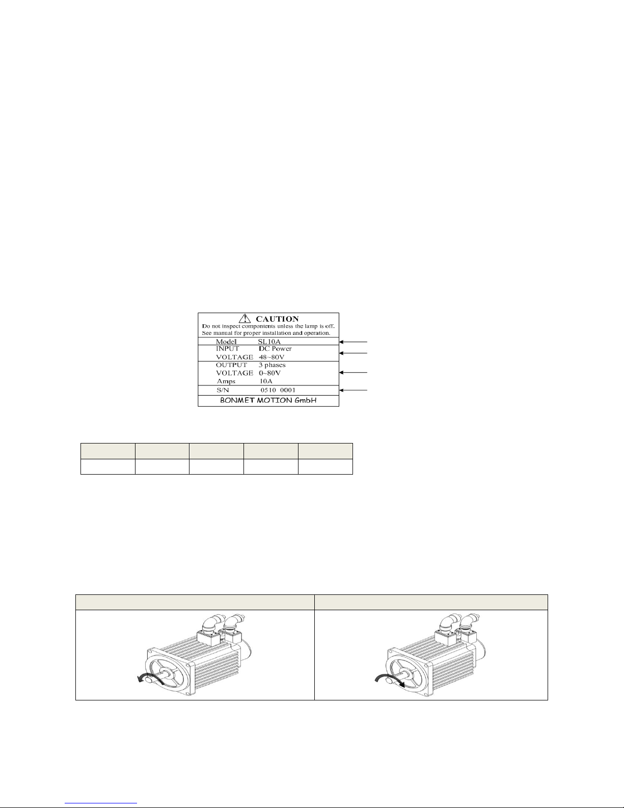
● Nameplate Explanation
Figure 1-1 Nameplate explanation
● Model Explanation
SD L 10 A XX 1 2 3 4
5
1. Product type: S(SD)- Series DC servo drive;
2. Power supply:48~80VDC
3. Nominal current:10A
4. Type code;
5. Software customized logo.
1.3 Product Features
●
Definition of The Motor Rotation Direction
Positive direction(CCW)
Negative direction(CW)
Definition of the motor rotation direction:facing the motor shaft side, CCW (counterclockwise) direction is
positive direction, CW (clockwise) direction is negative direction.
Model
Input Power
Nominal Output
Serial Number
Page 6
5
BONMET motion GmbH/www.bonmet.com/www.bonmet.de
Model
SDL10A
SDL10B
Input Power Supply
DC 24V~85V
Environment
Temperature
Operation:0~40℃ Storage:-40℃~50℃
Ambient Humidity
40%~80%( non-condensation)
Atmospheric Pressure
86~106kPa
Control Method
MOSFET
Control Mode
①Position control ②Speed control ③Torque control
Regeneration Brake
None
Speed
Characteristics
Speed Frequency
Response
300Hz or more
Speed Fluctuation Rate
±0.03 or less (Load 0~100%); ±0.02 or less (Power supply -15~+10%)
(Value corresponds to the nominal speed)
Speed Ratio
1:5000
Input Signal
Status Input Signal
Servo enable、Alarm clear
Command Input Signal
Analog torque / speed command input terminals、Pulse command input terminal
Output Signal
Status Output Signal
Servo alarm、Position complete output / speed reach output
Position Output Signal
Differential output for A、B、Z pulse, Open collector output for Z pulse
Position
Control
Maximum Input Pulse
Frequency
500KHz
Input mode
① Differential output ②Open collector output
Command mode
①Command/direction pulse ②CCW/CW pulse ③A/B pulse (set by parameters)
Command Smoothing
Method
Position command filter
Electronic Gear
1~30000/1~300000(Recommended value:50~1/50)
Torque Limit
①Set by parameters(CCW/CW)②16 speed command set by parameters
③Controlled by analog command
Speed
Control
Comma
nd mode
Internal
Command
16 speed command set by parameters,
Analog
Command
0~±10VDC(Default:10VDC corresponds 3000rpm)
Pulse
Command
0~500KHz(Default:500KHz corresponds 3000rpm)
Command Smoothing
① Analog low-pass filter order ②Increase / Decrease time constant ③ Position
command filter
Speed Limit
Set by parameters
Torque
Control
Command mode
0~±10VDC(Default:10VDC corresponds 100% nominal torque)
Command Smoothing
Torque command filter
Speed Limit
Set by parameters
Torque Limit
Set by parameters(CCW/CW)
Communication
RS-232 port、RS-485 port
Bus Control Function
Mod bus
Monitoring Function
The percentage of motor torque, ,Motor speed, Motor accumulated travel pulse,
Torque command value, Speed command value, Accumulative command pulse,
Single-phase current, Absolute position of rotor, Position deviation pulse, Alarm
code, Input and output terminal signal status, etc.
Protective Function
Encoder signal abnormalities, Overload, Over current, Speed tolerance, Over
location etc.
Applicable Load Inertia
Less than five times of motor inertia
Page 7
6
BONMET motion GmbH/www.bonmet.com/www.bonmet.de
Chapter 2 Installation
2.1 Notes for Installation
● Do not bend or strain the cables between servo drive and motor;
● When mounting the servo drive and servo motor, make sure to tighten all screws to secure the machine
in place;
● Motor shaft must be concentric with the axis of transmission;
● If the cable between drive and motor is longer than 10 meters, the cable must be thicken.
2.2 Installation Environment
● Please install the servo system in the place without oil mist, dust or electrical control cabinet (ensure the
temperature below 50℃, relative humidity below 80%. The long-term safety temperature below 40℃)
● Please install the servo system in the place without radioactive matters and combustibles.
● Take an anti-vibration measure to guarantee that the servo drive is free from vibration impact, ensuring
the vibration under 0.5G (4.9m/s2).
● Please install the servo system in the place without direct sunlight.
● Interferential equipment nearby would take great effects to the power wire and control wire which will
cause miss operation. For normal operation, a noise filter or any other anti-jamming measures is
necessary to be carried out. Leakage current would increase after installing a noise filter, therefore an
isolation transformer can be used to avoid this problem. Possessing a reasonable alignment and inhibit
measures is very important because the control signal wire is easy to be interfered.
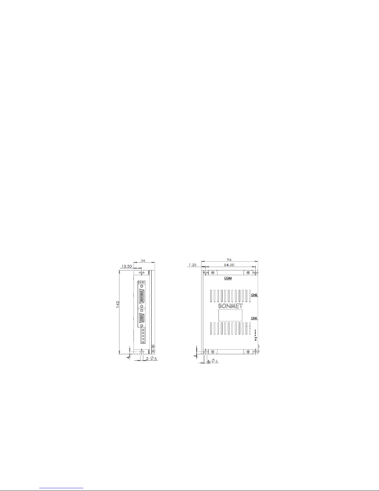
2.3 Dimensions(Unit: mm)
Figure 2-1 Dimension drawings
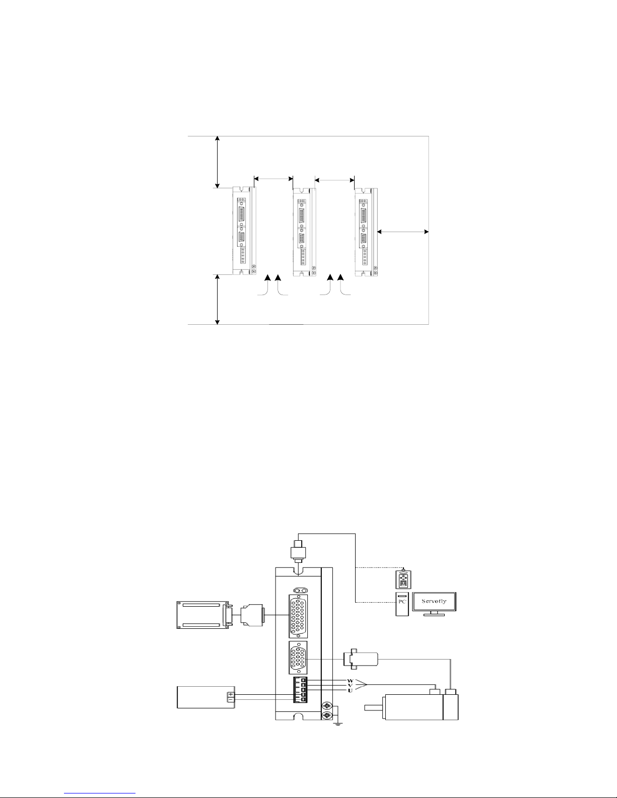
2.4 Installation Direction and Space
● The equipment must be installed in the specified direction. Otherwise, a fault may occur.
● Leave specified clearances between the servo drive and control box inside walls or other equipment.
● Leave a large clearance between the top of the servo drive and the internal surface of the control box,
and install a fan to prevent the internal temperature of the control box from exceeding the environmental
Page 8
7
BONMET motion GmbH/www.bonmet.com/www.bonmet.de
conditions.
● When using heat generating equipment such as the regenerative brake option, install them with full
consideration of heat generation so that the servo drive is not affected. Install the servo drive on a
perpendicular wall in the correct vertical direction.
Figure 2-2 installation schematic diagram for drives
Chapter 3 Wiring
2.5 Connections
3.1.1 Note
● All terminals and plugs must be screwed well, poor contact or disconnection could lead to accidents.
● In order to prevent error movement caused by noise, please install isolation transformers and noise filter.
● The equipment must be grounded.
● Do not put power lines and signal lines in a same conduit or their binding them together, the distance between
power lines and signal lines should be 30cm at least, otherwise it may cause interference.
● Please use the shielded twisted wire as signal cable.
● Do not switch power supply frequently. The maximum frequency should be no more than once per minute.
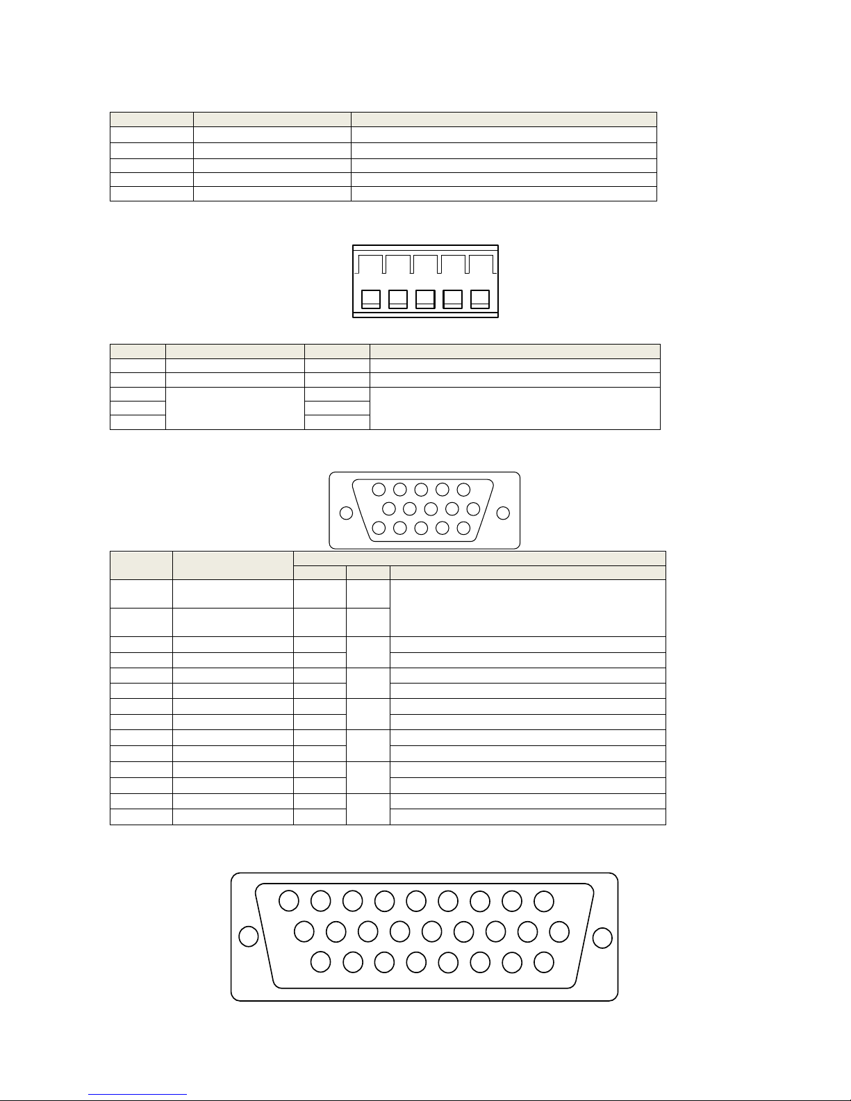
2.6 Connection
Control
Card
Power
48~80VDC
Motor
Controler
≥
25
mm ≥ 25
mm ≥ 100
mm
≥
100
mm
Air flow
Air flow
≥
100
mm
Page 9
8
BONMET motion GmbH/www.bonmet.com/www.bonmet.de
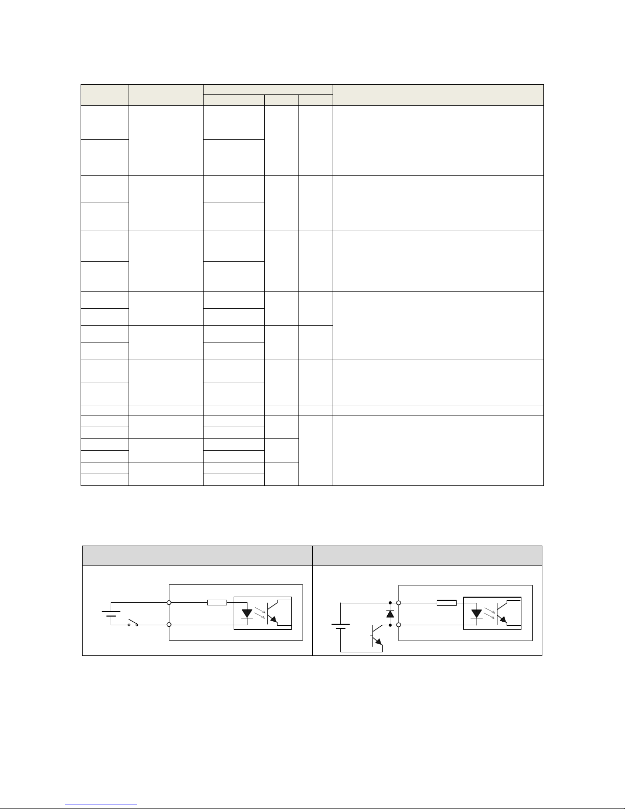
2.7 Terminals
Terminal
Name
Function
+VDC、GND
Drive power terminal
Connect with 48~80VDC
U、V、W
Motor terminal
Connect with motor
CN1
Encoder Connector
Connect with encoder
CN2
I/O Connector
I/O port
COM
Communication Connector
Connect with PC or controller
2.8 Power Terminal
number
Name
Symbol
Description
1
Ground
GND
Connect with OV
2
Power
+VDC
Connect with 48~80V
3
Motor U、V、W terminal
U
Connect with motor power terminal
4
V
5
W
2.9 Encoder Connector CN1
Terminal
number
Name
Function
Symbol
I/O
Description
1
Power supply(5V)
+5V
The power supply and public ground of encoder. It is
necessary to use a parallel multi-cored wire to reduce
the pressure drop of wires.
13
Public ground
0V
7
Encoder CSL input
CSL
Type7
Connect with the electro-optic encoder CSL.
2
Encoder CSH input
CSH
Connect with the electro-optic encoder CSH.
6
Encoder CLKL input
CLKL
Type7
Connect with the electro-optic encoder CLKL.
1
Encoder CLKH input
CLKH
Connect with the electro-optic encoder CLKH.
8
Encoder DOL input
DOL
Type7
Connect with the electro-optic encoder DOL.
3
Encoder DOH input
DOH
Connect with the electro-optic encoder DOH.
4
Encoder A+ input
A+
Type7
Connect with the electro-optic encoder A+.
9
Encoder A- input
A-
Connect with the electro-optic encoder A-.
5
Encoder B+ input
B+
Type7
Connect with the electro-optic encoder B+.
10
Encoder B- input
B-
Connect with the electro-optic encoder B-.
14
Encoder Z+ input
Z+
Type7
Connect with the electro-optic encoder Z+.
15
Encoder Z- input
Z-
Connect with the electro-optic encoder Z-.
2.10 I/O Connector CN2
1 2 3 4 5
1
2
3
45
10
11
12
13
1415
6
7
8
9
26
20
21
22
2324
25
1
2
3
45
19
6
78
9
17
1618
11
12
13
1415
10
Page 10
9
BONMET motion GmbH/www.bonmet.com/www.bonmet.de
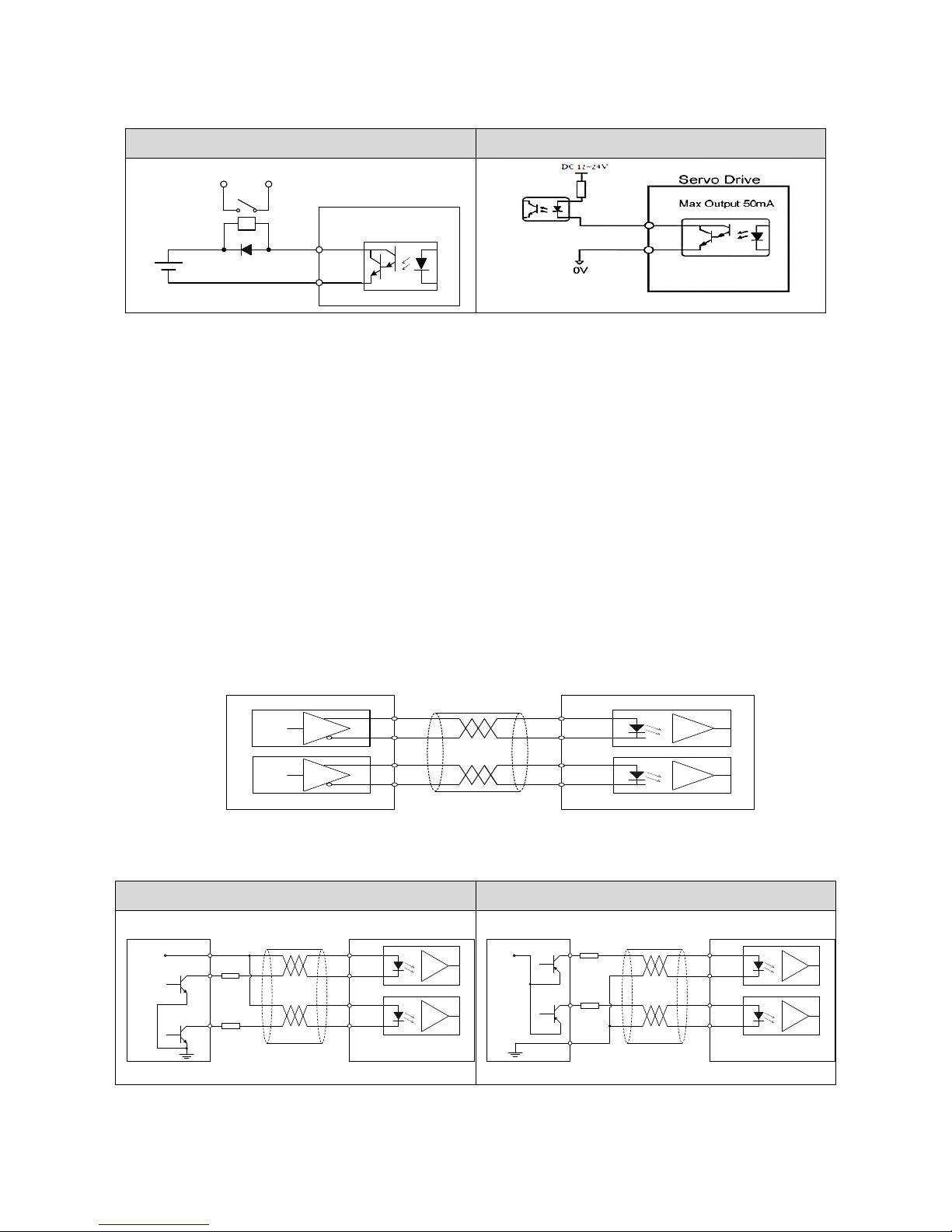
Control mode: P stands for position control, S stands for speed control, T stands for torque control.
Terminal
number
Name
Terminal symbol
Function
Symbol
I/O
mode
20
Servo enable
ServoEn+
Type1
Servo enable input terminal.
ServoEn ON: Operation enabled;
ServoEn OFF: Operation disabled.
[Note 1]: Make sure the servo motor is quiescent before
―ServoEn OFF‖ turns to ―ServoEn ON‖
[Note 2]: Please wait for 50 ms before inputting any
command in the State of ―ServoEn ON‖.
19
ServoEn-
3
Alarm clear
AlarmClr+
Type1
Alarm clear input terminal.
AlarmClr ON: Clear the system alarm;
AlarmClr OFF: Maintain the system alarm.
[Note]: As the alarm code is less than 12, please cut off
the power supply and repair the drive.
12
AlarmClr-
5
Servo alarm
output
Alarm+
Type2
Output terminal of servo alarm.
ALM ON: Servo alarm output ON as there is no alarm;
ALM OFF: Servo alarm output OFF as there is any
alarm.
14
Alarm-
2
Command pulse
PLUS input
PulseInv+
Type3
P
External command pulse input terminal.
Note: pulse type is selected by parameter PN52.
①PN52=0, command pulse+ signal mode(default state);
②PN52=1, CCW/CW command pulse mode;
③PN52=2, 2-phase command pulse mode.
11
PulseInv-
1
Command pulse
SIGN input
SignInv+
Type3
P
10
SignInv-
24
Analog command
input
ASPEED+/
ATORQUE+
Type4
S、T
Command input terminal for external analog
torque/speed (difference mode), the impedance is 10kΩ,
the voltage is -10V~+10V.
25
ASPEED-/
ATORQUE-
26
Analog ground
AGND
The grounding line of analog input.
7
Encoder
Phase-A signal
PhaseA+
Type5
1. Encoder signal A, B, Z for difference drive output
(output through 26LS31, corresponding to RS422 );
2. Non-isolative output (non-insulation).
16
PhaseA-
8
Encoder
phase-B signal
PhaseB+
Type5
17
PhaseB-
9
Encoder phase- Z
signal
PhaseZ+
Type5
18
PhaseZ-
3.6.1 Wiring of Digital Input
Wiring of the relay circuit
Wiring of the open collector circuit
(1) Connect to contacts of switches and relays, or open collector output transistors.
(2) The power is provided by the user as the voltage range is DC12~24V and the current is more than 100mA.
Note: the internal circuit will be damaged if the power polarity is wrongly connected.
4.7K
VCCOM
ServoEn,etc
DC 12~24V
Servo drive
4.7K
VCCOM
ServoEn,etc
DC 12~24V
Servo drive
Page 11
10
BONMET motion GmbH/www.bonmet.com/www.bonmet.de
3.6.2 Wiring of Digital Output
Wiring of the relay circuit
Wiring of the Optocoupler circuit
Note: it is possible to connect a freewheeling diode in the wiring of relay circuit.
(1) The output circuit is composed of open collector transistor outputs in the Darlington connection, and connect
to relays or photo-couplers.
(2) The power is provided by the user as the voltage range is DC5 ~ 24V and the current is more than 50mA.
Note: the internal circuit will be damaged if the power polarity is wrongly connected.
(3) As driving the inductive load such as relay, you must connect a freewheeling diode in parallel.
Note: It would damage the serve drive as if the freewheeling is wrongly connected.
(4) There exists collector to emitter voltage, VCE (SAT) of approx. 1V at transistor-ON, due to the Darlington
connection of the output or. Note that normal TTL IC cannot be directly connected since it does not meet
VIL.
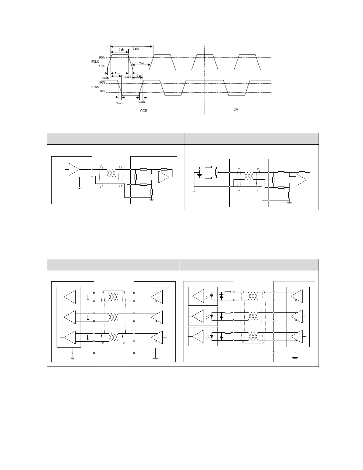
3.6.3 Wiring of Pulse Input
There are two kinds of pulse inputs, line drive input and open-collector input. The max. input pulse frequency is
500kpps.
BONMET servo drive support three kind of pulse mode (Set by Pn-52): ① Pulse + Direction; ② CW+CCW pulse;
③ A/B phase pulse
● Line drive input
● Open-collector input
There are two kind of open-collector input: NPN type (like Mitsubishi, Omron, Panasonic) and PNP type (like
Siemens). The wiring of open-collector as below:
Wiring of NPN type pulse input
Wiring of PNP type pulse input
⑴ Check the pulse input kind and make the wiring according to the drawing, otherwise it may cause the damage.
DC 12~24V
Servo drive
Relay
50mA as MAX.
output
Host controller
Servo drive
PULS+
PULS-
SIGN+
SIGN-
Servo drive
PULS+
PULS-
SIGN+
SIGN-
Host controller
R
R
VCC
Servo drive
PULS+
PULS-
SIGN+
SIGN-
Host controller
R
R
VCC
Page 12
11
BONMET motion GmbH/www.bonmet.com/www.bonmet.de
⑵ The Optocoupler supports max. to 15mA current. We need to add a current-limiting resistance as using
open-collector input.
Voltage of open-collector input
Value of current-limiting resistance
5V
Not need
12V
400
24V
1k
⑶ The cable of pulse input should be twisted-paired and shielded to prevent from signal interference caused by
noise.
⑷
The max. input pulse frequency is 500kpps, the relationship between pulse frequency and speed is a
proportional relationship as 500 kHz corresponds to 3000rpm.
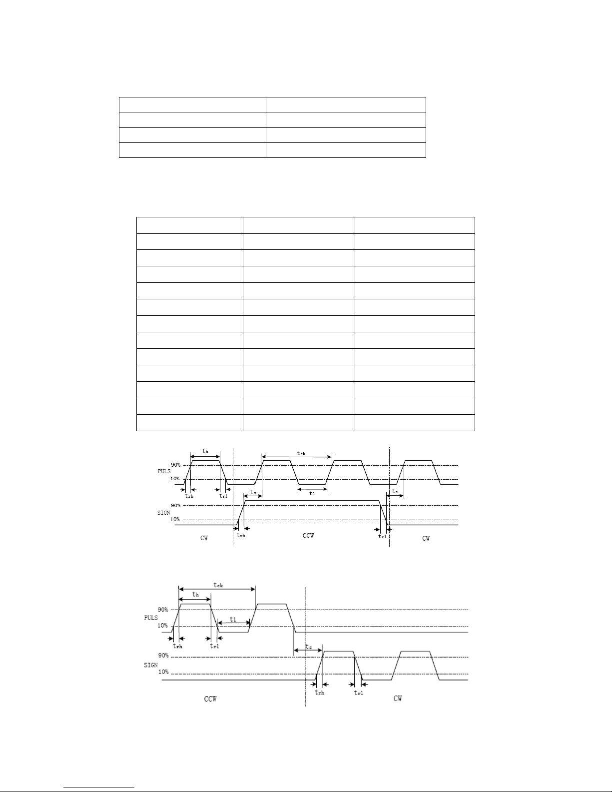
Parameters
Differential drive input
Single-ended drive input
tck
>2μS
>5μS
th
>1μS
>2.5μS
tl
>1μS
>2.5μS
trh
<0.2μS
<0.3μS
trl
<0.2μS
<0.3μS
ts
>1μS
>2.5μS
t
qck
>8μS
>10μS
tqh
>4μS
>5μS
tql
>4μS
>5μS
t
qrh
<0.2μS
<0.3μS
t
qrl
<0.2μS
<0.3μS
tqs
>1μS
>2.5μS
Sequence chart for pulse + direction
Sequence chart for CW+CCW pulse
Page 13
12
BONMET motion GmbH/www.bonmet.com/www.bonmet.de
Sequence chart for A/B phase pulse
3.6.4 Wiring of Analog Input
Analog voltage input
Potentiometer input
Note:"AO" means analog command.
(1) AGND must be connected to the ground (0V) of analog command;
(2) Max. permissible input voltage to each input is ±10V;
(3)
It is suggested that using Shielded twisted pair as the analog input cable;
(4) Analog input drift is normal, you can use analog input drift compensation function to deal with it..
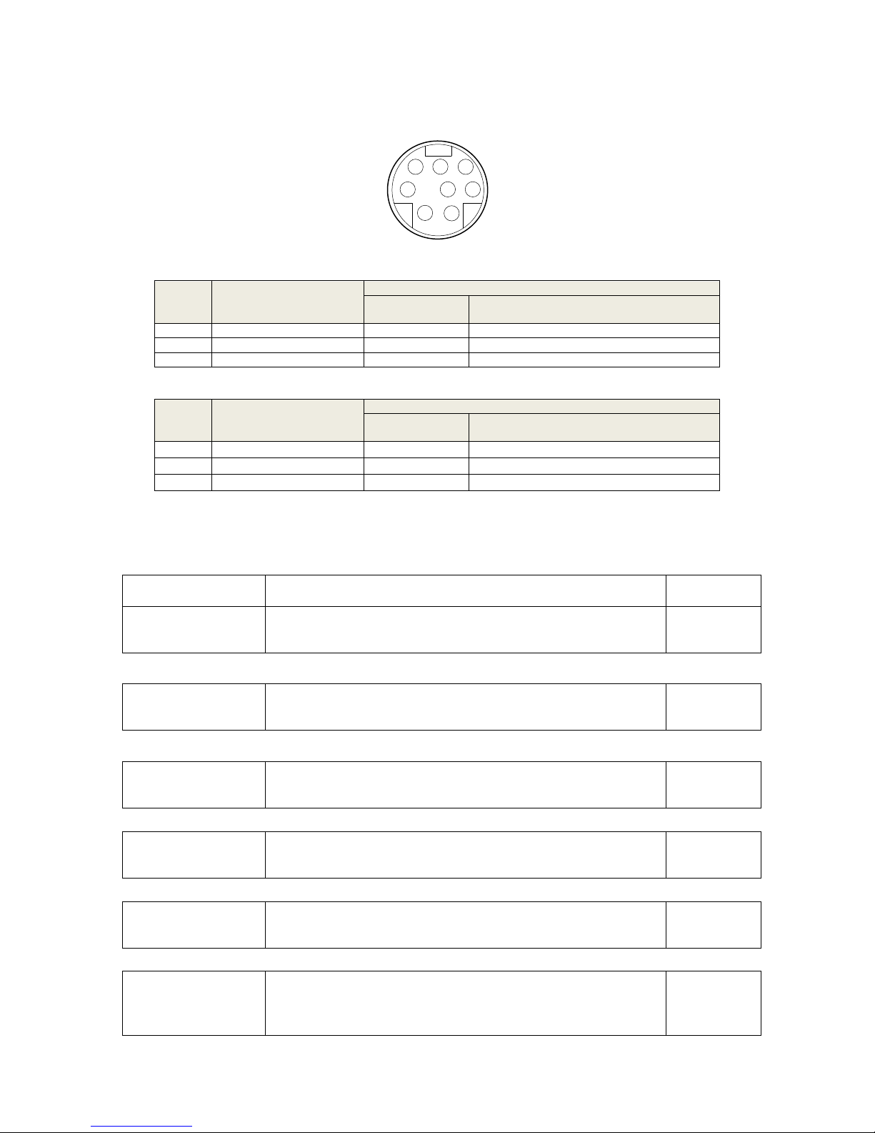
3.6.5 Wiring of Encoder Differential Output
Wiring of line receiver
Wiring of optocoupler
(1) Feeds out the divided encoder outputs (A, B and Z-phase) in differential through each line driver.
(2) Customer can use a line receiver (like AM26LV32). Install a terminal resistor (approx. 330Ω) between line
receiver inputs without fail. And connect ―EGND‖ to the ground (0V) of the receiver.
(3) Customer can use a optocoupler to receive the signals.
(4) These outputs are not insulated.
3.4
Servo drive
AO+
AO-
Host controler
+
-
+
-
AGND
10KΩ
AO+
AO-
Adjust voltage
by potentiometer
+
-
AGND
10KΩ
2KΩ(1/2W)
200Ω(1/2W)
200Ω(1/2W)
10V
10V
Servo drive
Servo drive
PhaseA+
PhaseA-
PhaseB+
PhaseB-
Host controler
PhaseZ+
PhaseZ-
Pin_1
Pin_2
Pin_3
Pin_4
Pin_5
Pin_6
R
EGNDPin_9
AM26LS31
AM26LV32 or other line receiver
R
R
Servo drive
PhaseA+
PhaseA-
PhaseB+
PhaseB-
Host controler
PhaseZ+
PhaseZ-
Pin_1
Pin_2
Pin_3
Pin_4
Pin_5
Pin_6
220Ω(1/2W)
220Ω(1/2W)
220Ω(1/2W)
EGNDPin_9
AM26LS31
Optocoupler
Page 14
13
BONMET motion GmbH/www.bonmet.com/www.bonmet.de
3.5 Communication Connector(CN3)
Serial-line terminal plug CN3
■ RS-232
Termina
l
number
Name
Function
Symbol
Description
3
Receive data
RXD
Receive data signal.
5
Transmit data
TXD
Transmit data signal.
1
GND
GND
Inhibit signal earth.
■ RS-485
Termina
l
number
Name
Function
Symbol
Description
7
Difference signal Data+
Data+
Data+ terminal
4
Difference signal Data-
Data-
Data- terminal
8
GND
GND
Inhibit signal earth.
Chapter 4 Operation
4.1 Operation steps
Item
Content
Reference
Installation
Please keep the motor shaft in a non-connection state, do not connect the motor
with mechanical system for servo action confirmation at first.
Chapter 2
↓
Wiring
Connect servo drive with power and peripheral device
Chapter 3
↓
Preparation before
operation
Please confirm all the necessary items before turn on the power. And check if
there is any alarm.
Chapter 4
↓
Action confirmation
Operate in speed mode to test the servo drive and servo motor without any load
on the shaft.
Chapter 4
↓
Parameters settings
Set parameters according to terms of use.
Chapter 5
↓
Trial operation
Connect motor with mechanical systems, turn on the power, and check whether
protective functions (such as emergency stop and stroke limit) are working.
Check operation at both low speed and high speed.
—
31 2
4 5 6
7
8
Page 15
14
BONMET motion GmbH/www.bonmet.com/www.bonmet.de
↓
Gain adjustment
Adjust the gain to get a good performance.
Chapter 4
↓
Normal operation
You can carry out normal operation now. If any faulty happens, please refer to
"Chapter 7 Protection."
Chapter 7
Preparing For Operation
Turning Power ON and Checking Indicators
■ Checking Power Supply Voltage
· Check to be sure that the power supply voltage is 24~85VDC
■ Checking Terminal Block Wiring
· The power supply inputs (+VDC、GND)must be properly connected to the terminal block.
· The servo motor‘s power line(U、V、W)must be properly connected to the terminal block.
■ Checking the servo motor
· The Encoder Cable must be securely connected to the Encoder Connector at the motor side.
· The power lines at the servo motor must be securely connected.
■ Checking the Control Connectors
· The Control Cable must be securely connected to the I/O Control Connector (CN2).。
· The ServoEn command must be OFF.
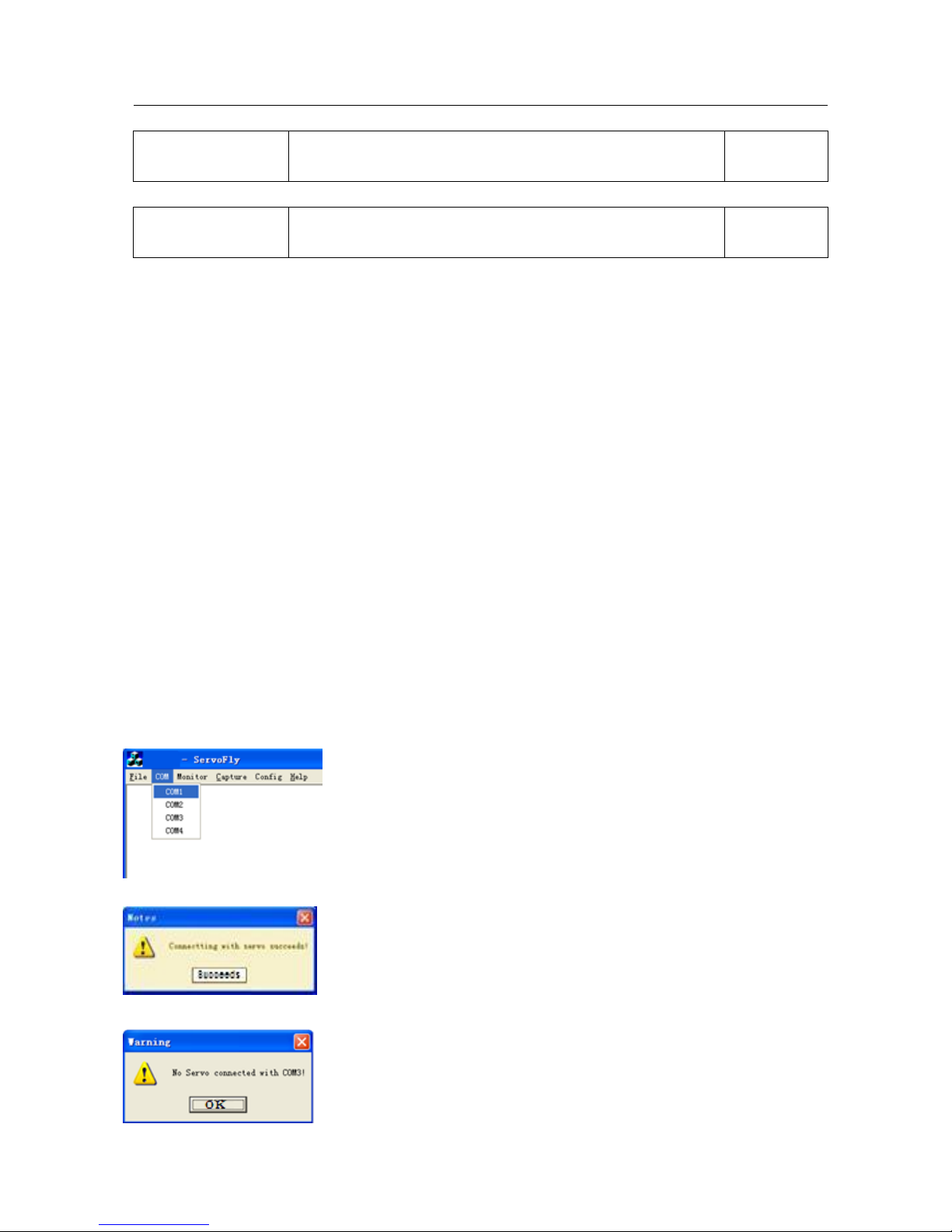
4.2 Software(Servofly)operation instructions
4.2.1 Communication
⑴ Connect servo drive with PC through serial cable.
⑵ Click “Servofly.exe‖ and select the COM menu,click the defined COM port(can be modified by PC).
⑶ The communication succeeds as the following dialog appears.
⑷ The communication fails as the following dialog appears, please check the wiring.
Page 16
15
BONMET motion GmbH/www.bonmet.com/www.bonmet.de
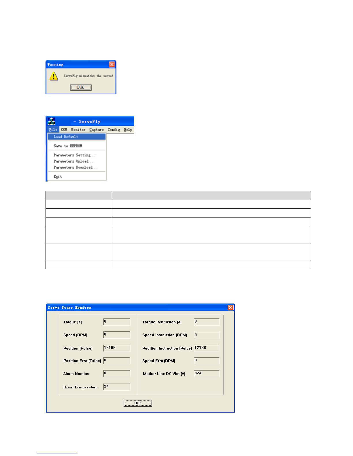
⑸ The communication fails as the following dialog appears, it indicates that the software version does not match,
please select Pn-0 to check the version information, and download the right software on our website.
4.2.2 Basic function
1. Customers can use the basic function of the software in the ―File‖ menu.
2. Function
Item
Function
Load Default
Restore default parameters(equal with ―EE-Def‖ in panel operation)
Save to EEPROM
Save the current parameters to EEPROM
Parameters Setting…
Parameter setting
Parameters Upload…
Upload the parameters from servo drive to PC ( please name the parameter file as
“xx.par”, otherwise the operation would be invalid)
Parameters Download…
Download the parameters from PC to servo drive(please DO NOT use this
function.)
Exit
Exit the software
4.2.3 Monitoring function
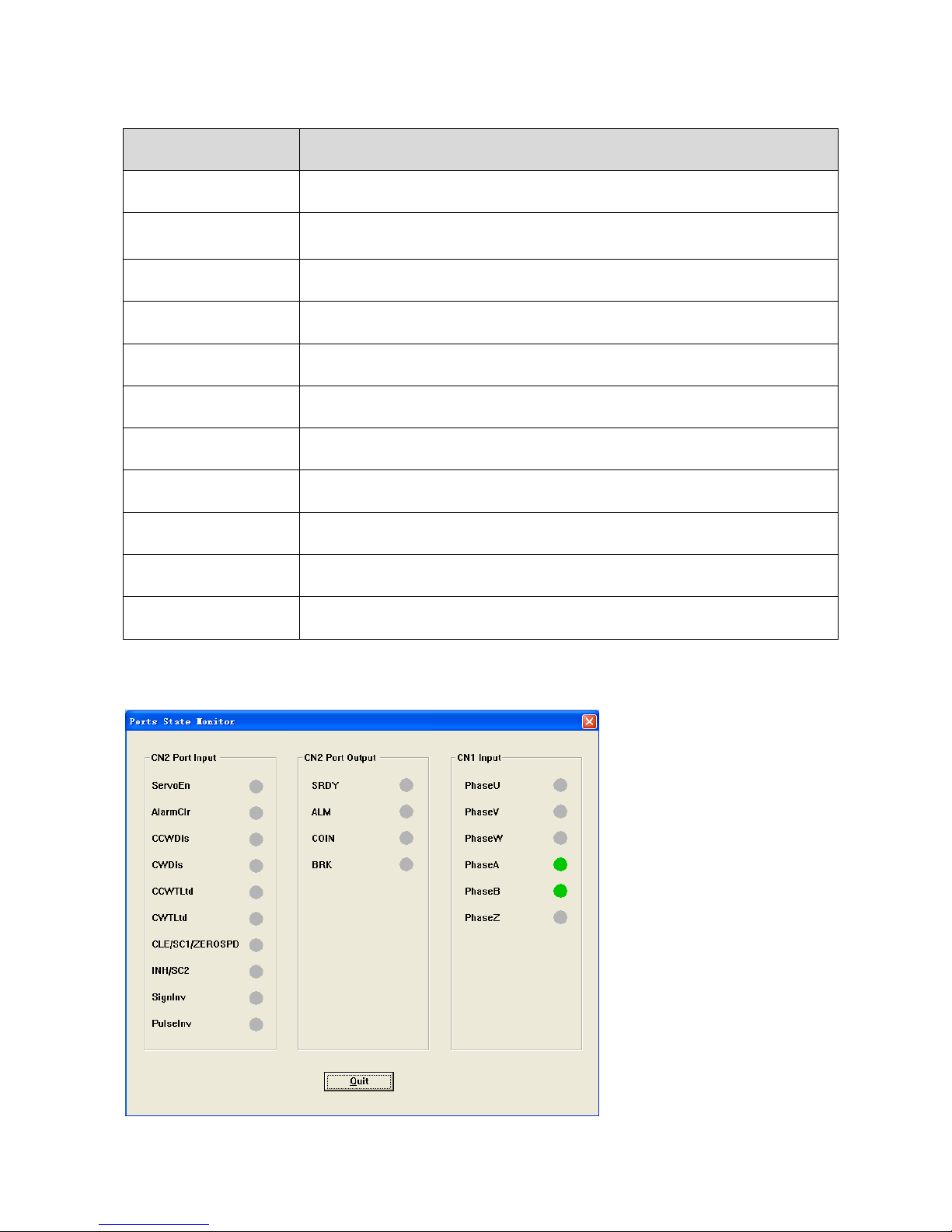
1. Monitoring the servo state
⑴ ―Servo State‖ choice under the ―Monitor‖ menu is the monitoring choice of the servo state.
Page 17
16
BONMET motion GmbH/www.bonmet.com/www.bonmet.de
⑵ Function
Item
Function
Torque(A)
Motor Q axis current(the value divided by 1.414 is motor current)
Torque Instruction(A)
Motor Q axis current command (the value divided by 1.414 is motor current
command)
Speed(RPM)
Motor speed(this is a real time value )
Speed Instruction(RPM)
Speed command
Position(Pulse)
Feedback pulse
Posiotn Instruction(Pulse)
Pulse command
Position Erro(Pulse)
Position deviation (pulse command minus feedback pulse)
Speed Erro(Pulse)
Speed deviation(this is a real time value)
Alarm Number
Alarm code(―0‖ means no alarm)
Mother Line DC Vlot(V)
Mother line DC voltage
Drive Temperature
The temperature of the heat sink inside part
② Physical port status monitoring function
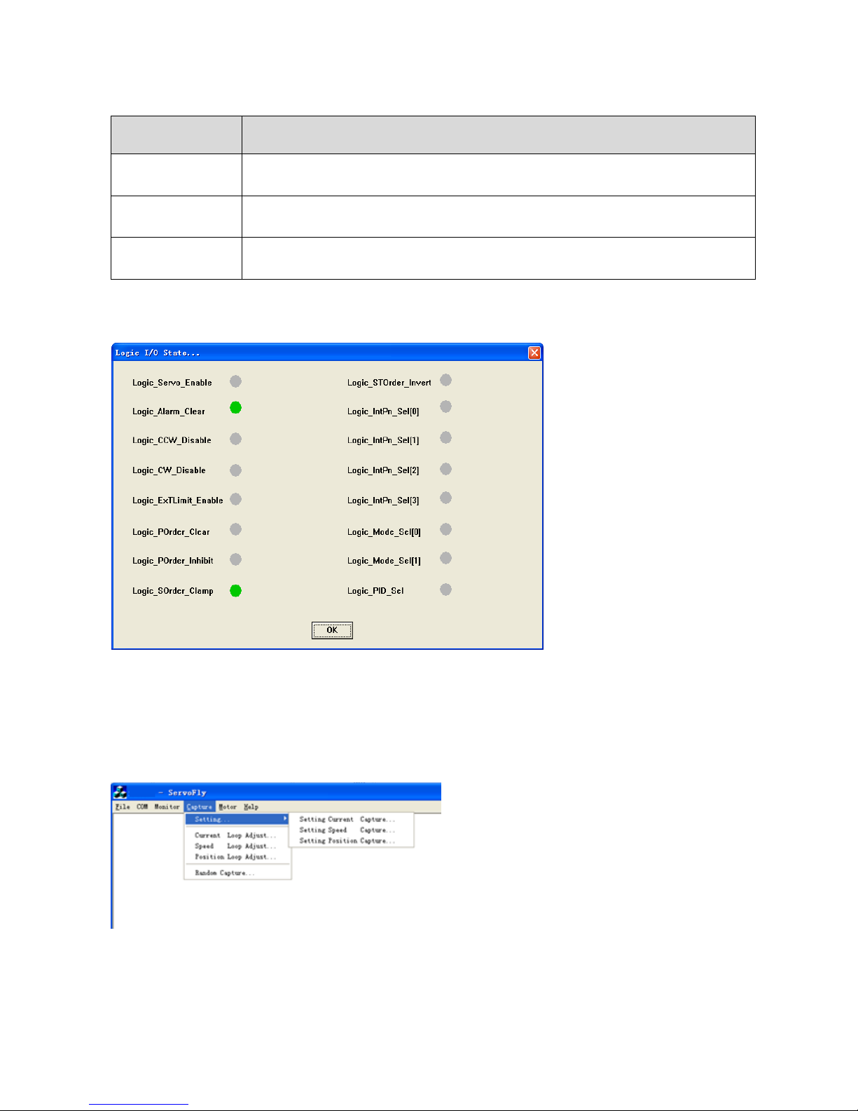
⑴ The ―Physical State‖ item under the ―Monitor‖ menu is for the physical port status monitoring function.
Page 18
17
BONMET motion GmbH/www.bonmet.com/www.bonmet.de
⑵ Function
Item
Function
CN2 Port Input
Monitor the digital input status, green light indicates “ON” and grey light indicates
“OFF” , please refer to chapter 3 for details of I/O connector
CN2 Port Output
Monitor the digital output status, green light indicates “ON” and grey light indicates
“OFF” , please refer to chapter 3 for details of I/O connector
CN1 Port Input
Encoder input signals, green light indicates “ON” and grey light indicates “OFF” ,
please refer to chapter 3 for details of I/O connector
③ Logical port status monitoring function
⑴ The ―Logic State‖ item under the ―Monitor‖ menu is for the logical port status monitoring function.
⑵ Function
Monitor the logical input status, green light indicates “ON” and grey light indicates “OFF” , please refer to
chapter 3 section 3.7 for details of logical input.
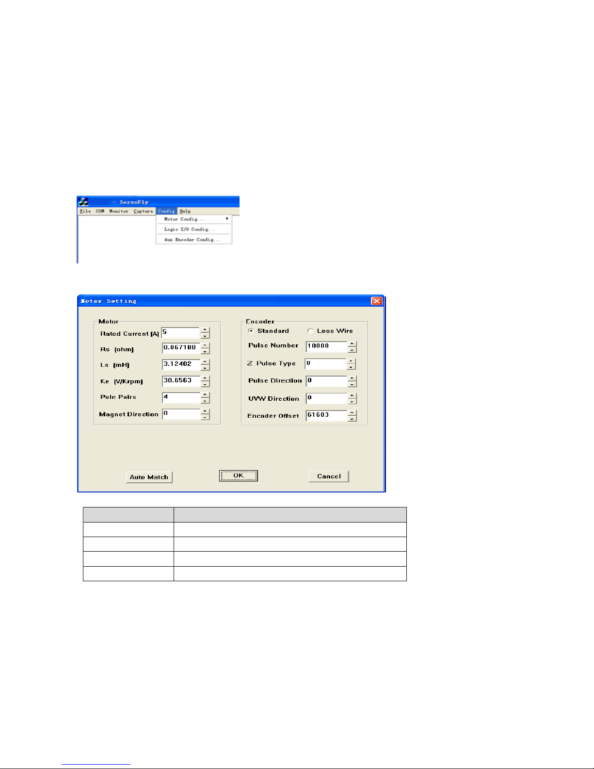
4.2.4 Oscillation control and running curve monitoring function
1. Oscillation control
In the picture, the items “Setting„”, “Current Loop Adjust„”, “Speed Loop Adjust„” and “Position
Loop Adjust„” are for oscillation control, this function is only for factory testing use, wrong operation may
cause damage, please DO NOT use this function.
Page 19
18
BONMET motion GmbH/www.bonmet.com/www.bonmet.de
2. Running curve monitoring function
―Random Capture‖ menu is for the running curve monitoring function, customers can check the current loop
curve, speed loop curve and position loop curve.
4.2.5 Config function
There are two items ―Motor Config…‖ and ―Logic I/O Config…‖ under the ―Config‖ menu. The “Aux Encoder
Config…” item DOES NOT open to customers.
1. Motor parameters adaptive function
⑴ Click ―Basic Information…‖ and the following dialog will appear:
⑵ Fill in the basic data (please don‘t fill in other parameters)
Item
Function
Rated Current(A)
Motor nominal current
Rs(ohm)
Phase resistance
Ls(mH)
Phase inductance
Ke(V/Krpm)
Back EMF
Note:This operation must be carried out by electrical engineer and the above parameters must be effective,
otherwise it would cause mistake or damage.
⑶ Adaption
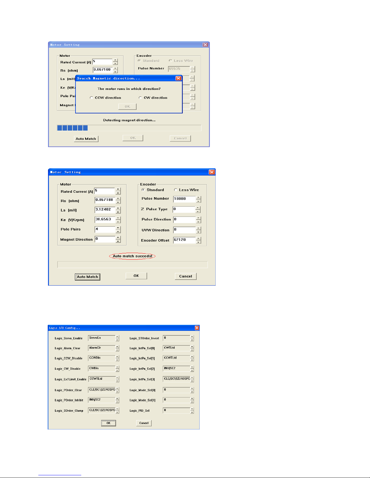
Click ―Auto Match‖ to start the adaption operation, as the following dialog appears, select the right direction(face
the motor shaft, ―CCW direction‖ indicates counterclockwise direction and ―CW direction‖ indicates clockwise0
direction), and then click ―OK‖.
Page 20
19
BONMET motion GmbH/www.bonmet.com/www.bonmet.de
The following dialog will appear as if the adaption is successful, please save the parameters to EEPROM and
power off, then power on again.
⑷ If adption is not successful, maybe there is something wrong with the operation, please contact with out
technical staff.
2. Mapping function
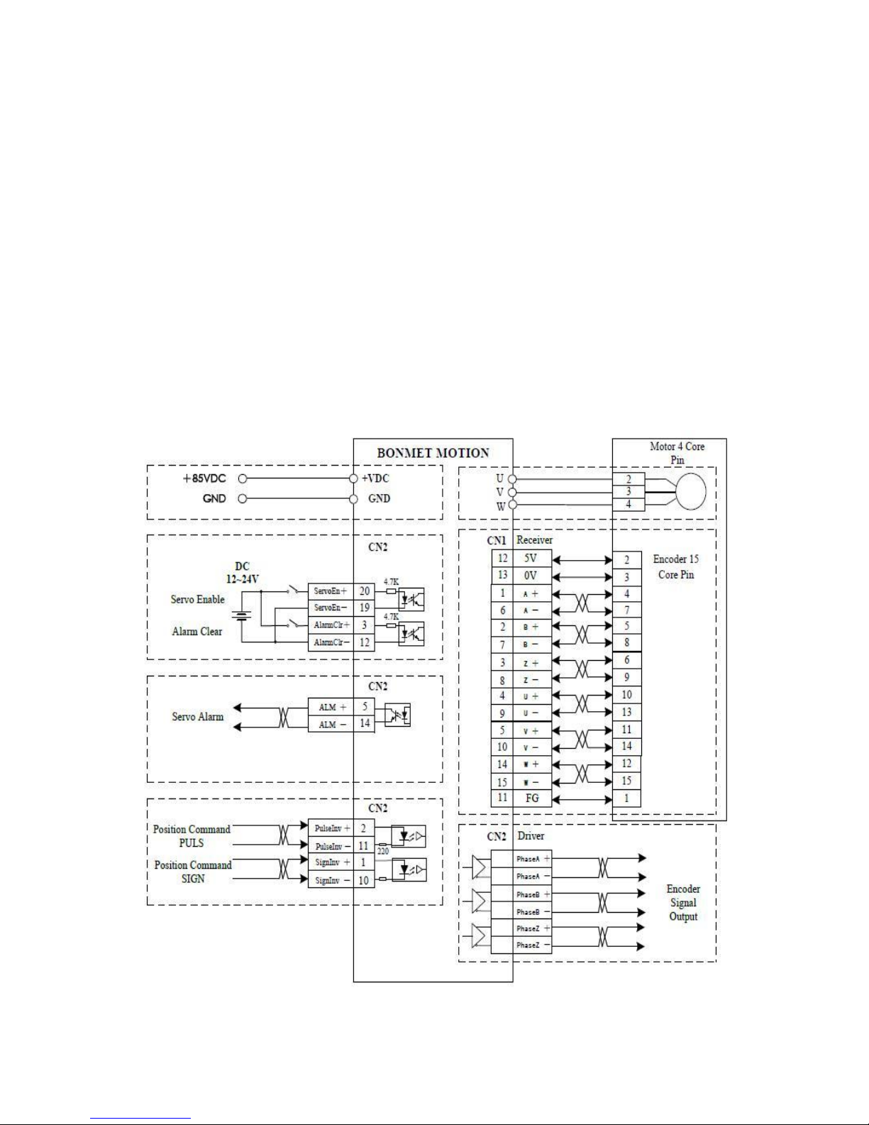
⑴ Click ―Logic I/O Config...‖ and the follow dialog will appear:
Page 21
20
BONMET motion GmbH/www.bonmet.com/www.bonmet.de
⑵ The left side part which can not be modified is the logic signal name, the right side part which can be modified
by customers is the mapping port. Customers can use UP button and DOWN button to set the mapping method,
then click ―OK‖.
Note: ―0‖ indicates OFF or invalid, ―1‖ indicates ON or valid.
⑶ Please refer to chapter 3 for each logic input signal definition.
⑷ Please confirm that the mapping method is unique, otherwise it would cause abnormal conditions.
4.3 Position Control Mode
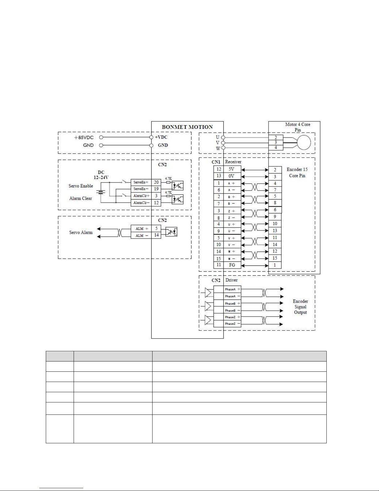
● Three type optional input pulse command (pulse + direction pulse, CCW+CW pulse, A /B phase pulse )
● Two types of input signal optional(open collector signal、differential signal)
● Optional electric gears
●
The number of dividing pulse
● Speed limitation and torque limitation can be set
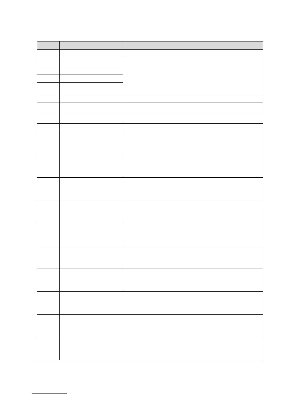
4.3.1 Terminal Diagram
Page 22
21
BONMET motion GmbH/www.bonmet.com/www.bonmet.de
4.3.2 Parameters Settings
No.
Parameter
Function
Pn-4
Motor control mode
Select position control mode(Value: 2)
Pn-48
Denominator of electric gear
Two sets of electronic gear can be switched by the external trigger signal.
Pn-49
Numerator 1 of electric gear
Pn-50
Numerator 2 of electric gear
Pn-51
Dynamic electronic gear function
enable
Pn-52
External Pulse Input Type
Select the pulse command type.
Pn-53
Invert of pulse command
direction
The direction of position command can be inverted with this function.
Pn-55
Position error detection range
The drive will issue position tolerance alarm when the position offset counter
value exceeds the selected value×100 in position control mode.
Pn-56
Position error detection function
Set this parameter to enable the position error function or not.
Pn-30
The first speed loop proportional
gain
The value is determined by the type of servo and the load condition. In general,
larger load inertia needs larger value. It can be switched with the second speed
loop proportional gain automatically or manually (refer to chapter 5 section
4.8).
Pn-31
The first speed loop integral time
constant
The value is determined by the type of servo and the load condition. In general,
larger load inertia needs larger value. It can be switched with the second speed
loop integral time constant automatically or manually (refer to chapter 5
section 4.8).
Pn-32
The first low-pass bandwidth of
speed loop
Normally, smaller value results in slower and smoother speed response. But
too much small value may cause system oscillation. It can be switched with the
second low-pass bandwidth of speed loop automatically or manually (refer to
chapter 5 section 4.8).
Pn-33
The first low-pass filter
bandwidth of torque command
Normally, smaller value results in slower and smoother speed response. But
too much small value may cause system oscillation. It can be switched with the
second low-pass filter bandwidth of torque command automatically or
manually (refer to chapter 5 section 4.8).
Pn-36
The second speed loop
proportional gain
The value is determined by the type of servo and the load condition. In general,
larger load inertia needs larger value. It can be switched with the first speed
loop proportional gain automatically or manually (refer to chapter 5 section
4.8).
Pn-37
The second speed loop integral
time constant
The value is determined by the type of servo and the load condition. In general,
larger load inertia needs larger value. It can be switched with the first speed
loop integral time constant automatically or manually (refer to chapter 5
section 4.8).
Pn-38
The second low-pass bandwidth
of speed loop
Normally, smaller value results in slower and smoother speed response. But
too much small value may cause system oscillation. It can be switched with the
first low-pass bandwidth of speed loop automatically or manually (refer to
chapter 5 section 4.8).
Pn-39
The second low-pass filter
bandwidth of torque command
Normally, smaller value results in slower and smoother speed response. But
too much small value may cause system oscillation. It can be switched with the
first low-pass filter bandwidth of torque command automatically or manually
(refer to chapter 5 section 4.8).
Pn-44
The first Position loop
proportional gain
Higher gain results in greater mechanical stiffness and less position tracking
error. Too large value may cause overshoot or oscillation. It can be switched
with the second Position loop proportional gain automatically or manually
(refer to chapter 5 section 4.8).
Pn-45
The first position loop differential
proportional gain
Higher gain results in greater mechanical stiffness and less position tracking
error. Too big value may cause overshoot or oscillation; This parameter is
usually set to zero unless very fast response is required. It can be switched with
the second position loop differential proportional gain automatically or
Page 23
22
BONMET motion GmbH/www.bonmet.com/www.bonmet.de
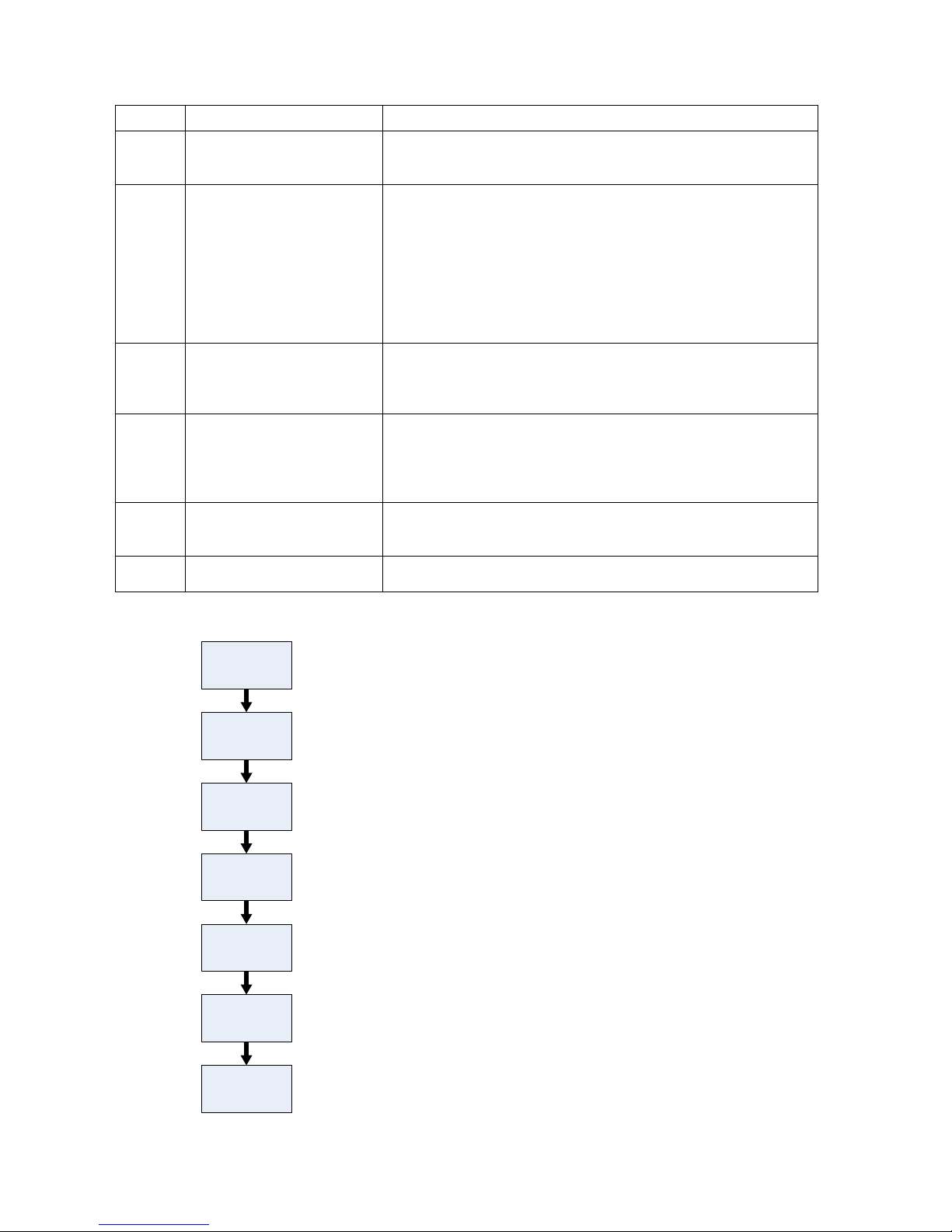
4.3.3 Operation Flow Chart
Select input
pulse command
type
Select rotation
direction
Set Pn-4 to 2
Select electronic
gear function
Set ServoEn ON
Host sends pulse
command for a
trial operation
⑴ Select position control mode.
⑵ Select input pulse command type (support pulse/direction pulse ,
CCW/CW pulse, A phase/B phase pulse ) by Pn-52.
⑶ Select rotation direction by Pn-53.
⑷ Select electronic gear ratio by Pn-48, Pn-49, Pn-50.
⑸ Set signal “ServoEn” ON or set Pn-8 to 100000,
and the motor get the power.
Adjust the servo
gain
⑹ In no-load conition (leave the motor shaft free), send pulse command
for forward, reverse, acceleration / deceleration and other operation
for a trial operation.
⑺ Make a trial processing and adjust the servo gain according to the
running status.
manually (refer to chapter 5 section 4.8).
Pn-46
The first cut-off frequency of
position feed forward filter
The filter is used to increase the stability of compound position control. It can
be switched with the second cut-off frequency of position feed forward filter
automatically or manually (refer to chapter 5 section 4.8).
Pn-47
Constant of position command
filter
①Smoothen filter for the command pulse with the accelerate of index form,
the value stands for time constant. The unit is ms;
Filter would not lose input pulse but may lead to delay;
The filter works in the follow conditions:
● Host controller has not acceleration and deceleration function;
● Larger electronic gear ratio (>10);
● Lower command frequency;
● Motor running with jumps or other unstable conditions;
Filter is inactive as set to 0.
Pn-66
The second Position loop
proportional gain
Higher gain results in greater mechanical stiffness and less position tracking
error. Too large value may cause overshoot or oscillation. It can be switched
with the first Position loop proportional gain automatically or manually (refer
to chapter 5 section 4.8).
Pn-67
The second position loop
differential proportional gain
Higher gain results in greater mechanical stiffness and less position tracking
error. Too big value may cause overshoot or oscillation; This parameter is
usually set to zero unless very fast response is required. It can be switched with
the first position loop differential proportional gain automatically or manually
(refer to chapter 5 section 4.8).
Pn-68
The second cut-off frequency of
position feed forward filter
The filter is used to increase the stability of compound position control. It can
be switched with the first cut-off frequency of position feed forward filter
automatically or manually (refer to chapter 5 section 4.8).
Pn-69
Enhancement of torque loop
response function
As set the value to 1, it can enhance the response of the torque, but it may
cause some current noise in the motor.
Page 24
23
BONMET motion GmbH/www.bonmet.com/www.bonmet.de
4.3.4 Function
1. Position error detection function(Related parameters:Pn-56, Pn-55)
⑴ The function is only effective in position mode and point to point mode, if the position deviation exceeds a
threshold value, it would occur Err-16;
⑵ Set Pn-56 to 0, enable the position error detection function;
⑶ Set the threshold alarm value by Pn-55, the servo drive would alarm as the position deviation (difference
between pulse command and actual stroke position) exceeds the threshold value.
The threshold alarm value = the value of Pn-55 *100pulse
2. Electronic gear function(Related parameters:Pn-48, Pn-49, Pn-50,Pn51)
⑴
Po:The required pulse number per round
P: Encoder resolution
G: Electronic gear ratio
For example:the encoder resolution of SM110-050-30LFB is 10000ppr, if you want count 1000pulse per round,
Then you should set Pn-49 to 10 and Pn-48 to 1.
Figure 5-4 Electronic function
⑵
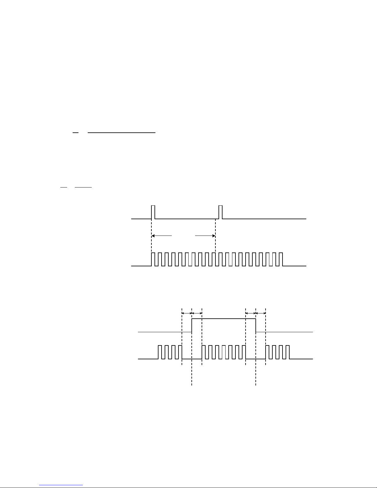
Set Pn-51 to 1 to enable dynamic electronic gear function, customers can switch two sets of electronic gear by
the logic control signal‖ Logic_IntPn_Sel [0]‖.
Figure 5-5 Dynamic electronic gear function
The process pulse command
by the electronic gear
Pulse command from host
10 pulse
Position command
Switching the ratio by digital signal OFF ON OFF
Electronic gear ratio
First electronic
gear ratio
Pn-49/Pn-48
Second electronic
gear ratio
Pn-50/Pn-48
First electronic
gear ratio
Pn-49/Pn-48
t1,t2,t3,t4>10ms
t1 t2 t3 t4
Page 25
24
BONMET motion GmbH/www.bonmet.com/www.bonmet.de
4.4 Analog Speed Control Mode
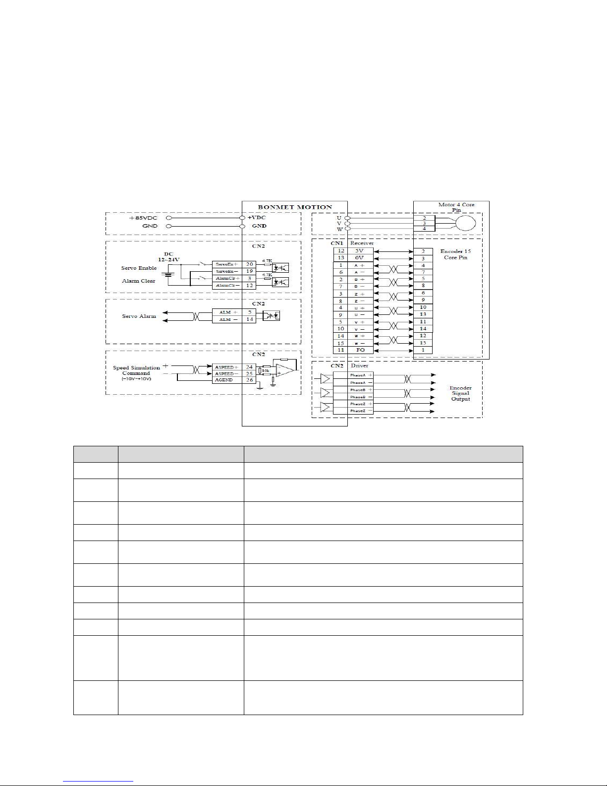
● ±10V Analog input, control the motor speed and torque simultaneously
●
Control through the I / O port,
●
Acceleration / deceleration time setting
● Support encoder output
● Speed limitation and torque limitation can be set
4.4.1 Terminal Diagram
4.4.2 Parameters Settings
No.
Parameter
Function
Pn-4
Motor control mode
Select speed control mode(Value: 1)
Pn-15
Gain of analog torque command
input
Set the ratio between the input voltage of analog torque and actual motor torque
Pn-18
Gain of analog speed command
input
Set the ratio between the input voltage of analog speed and actual motor speed.
Pn-19
Analog input drift compensation
The zero-bias compensation for the analog speed input.
Pn-20
Direction inversion of analog
speed input
Set the rotation direction.(Effective in analog speed mode)
Pn-21
Low-pass bandwidth of analog
speed input
Set the response time of speed analog input.
Pn-34
Acceleration time constant
Set the acceleration time constant.
Pn-35
Deceleration time constant
Set the deceleration time constant.
Pn-40
Command type of speed control
Select command type.(Value:1)
Pn-30
The first speed loop proportional
gain
The value is determined by the type of servo and the load condition. In general,
larger load inertia needs larger value. It can be switched with the second speed
loop proportional gain automatically or manually (refer to chapter 5 section
4.8).
Pn-31
The first speed loop integral time
constant
The value is determined by the type of servo and the load condition. In general,
larger load inertia needs larger value. It can be switched with the second speed
loop integral time constant automatically or manually (refer to chapter 5 section
Page 26
25
BONMET motion GmbH/www.bonmet.com/www.bonmet.de
4.8).
Pn-32
The first low-pass bandwidth of
speed loop
Normally, smaller value results in slower and smoother speed response. But too
much small value may cause system oscillation. It can be switched with the
second low-pass bandwidth of speed loop automatically or manually (refer to
chapter 5 section 4.8).
Pn-33
The first low-pass filter
bandwidth of torque command
Normally, smaller value results in slower and smoother speed response. But
too much small value may cause system oscillation. It can be switched with the
second low-pass filter bandwidth of torque command automatically or
manually (refer to chapter 5 section 4.8).
Pn-36
The second speed loop
proportional gain
The value is determined by the type of servo and the load condition. In general,
larger load inertia needs larger value. It can be switched with the first speed
loop proportional gain automatically or manually (refer to chapter 5 section
4.8).
Pn-37
The second speed loop integral
time constant
The value is determined by the type of servo and the load condition. In general,
larger load inertia needs larger value. It can be switched with the first speed
loop integral time constant automatically or manually (refer to chapter 5 section
4.8).
Pn-38
The second low-pass bandwidth
of speed loop
Normally, smaller value results in slower and smoother speed response. But too
much small value may cause system oscillation. It can be switched with the first
low-pass bandwidth of speed loop automatically or manually (refer to chapter 5
section 4.8).
Pn-39
The second low-pass filter
bandwidth of torque command
Normally, smaller value results in slower and smoother speed response. But
too much small value may cause system oscillation. It can be switched with the
first low-pass filter bandwidth of torque command automatically or manually
(refer to chapter 5 section 4.8).
Pn-69
Enhancement of torque loop
response function
As set the value to 1, it can enhance the response of the torque, but it may cause
some current noise in the motor.
4.4.3 Operation Flow Chart
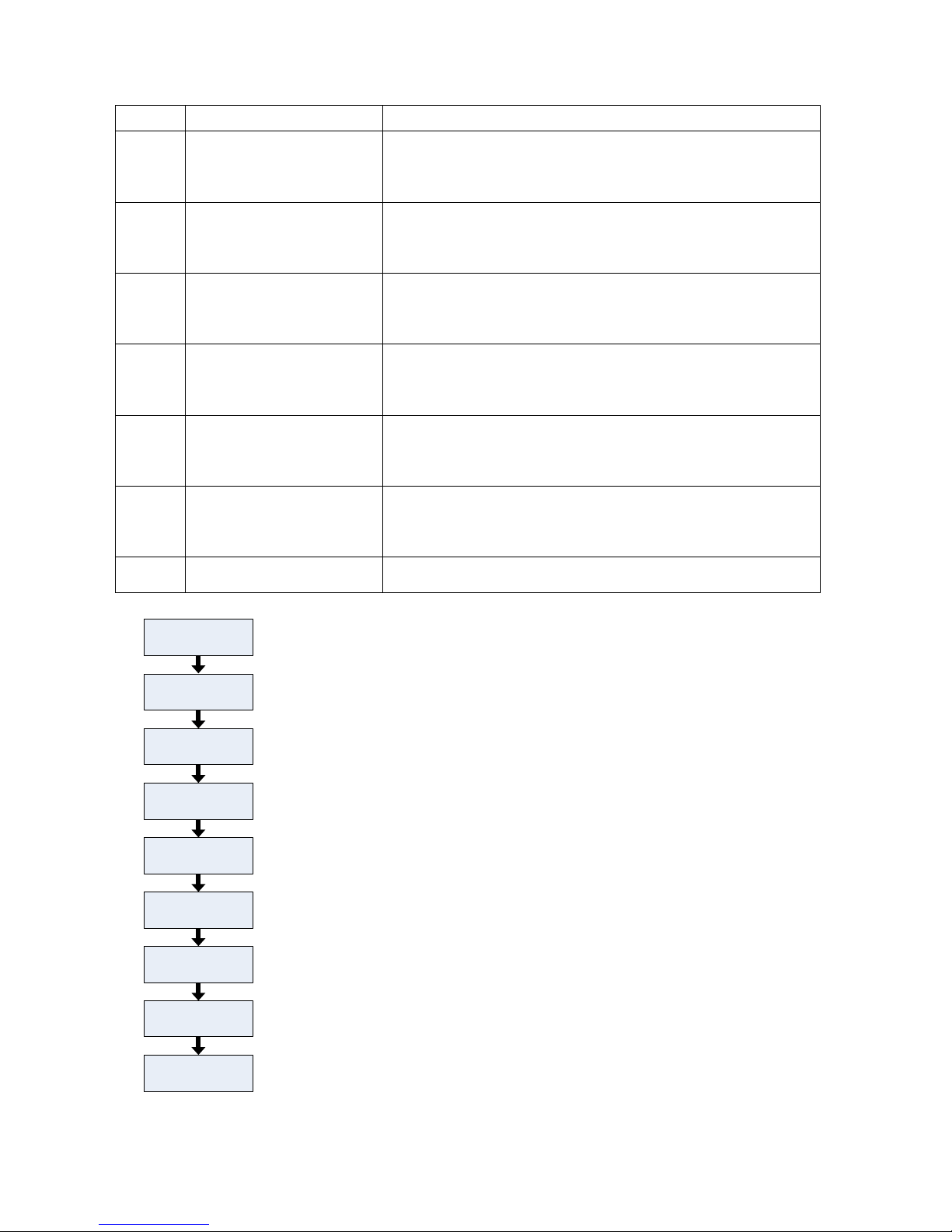
Figure 5-7 Operation Flow Chart
Set analog gain
of torque control
by Pn-18
Select rotation
direction
Set Pn-4 to 1
Set the
acceleration and
deceleration time
⑴ Select speed control mode.
⑵ Set the analog gain to select the relationship between analog voltage
and speed command, 3000rpm according to 10V for default.
⑶ Select rotation direction by Pn-20 or switch the direction by digital
input “Logic_STOrder_Invert”
⑷ Set Pn-34 for acceleration time and Pn-35 for deceleration time.
Analog input
drift
compensation
⑹ Set parameter Pn-19 to clear the analog
input drift.
Host sends pulse
command for a
trial operation
⑺ In no-load conition (leave the motor shaft free), send pulse command
for forward, reverse, acceleration / deceleration and other operation
for a trial operation.
Adjust the servo
gain
⑻ Make a trial processing and adjust the servo gain according to the
running status.
Set ServoEn ON
⑸ Set signal “ServoEn”ON or set Pn-8 to 100000, and the motor get the
power.
Set Pn-40 to 1
⑵ Select analog voltage as speed command by Pn-40.
Page 27
26
BONMET motion GmbH/www.bonmet.com/www.bonmet.de
Function
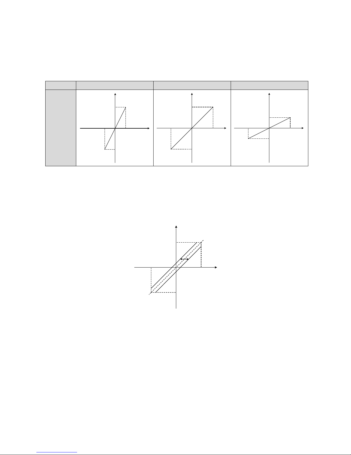
1. Analog gain setting function(Related parameters:Pn-18)
Set the ratio between the input voltage of analog speed and actual motor speed.,they are proportional relationship.
Value of Pn-18=(Max. input/Max. speed command)30000。The default value is 100,which means 10Vsupport
speed command of 3000rpm.
Item
Pn-18=50
Pn-18=100
Pn-18=200
Relationship
of input
voltage and
output speed
2. Analog input drift compensation function(Related parameters:Pn-19)
● Customers can use the analog input drift compensation function to deal with the analog input drift.
⑴ Make a correct wiring and set the analog voltage to 0V.
⑵
Check the motor speed by the drive monitor functions, adjust the value of the parameter Pn-19 to compensate.
As the zero-drift speed is a positive value, the parameter should be set a positive value; while the zero-drift speed
is a negative value, the parameter should be set a negative value.
3. Acceleration / deceleration time setting(Related parameters:Pn-34,Pn-35)
⑴
In case of overloading, it is suggested to set the acceleration / deceleration time to avoid the impact of the
instantaneous large current to avoid error or failure.
⑵ Set the value of Pn-34 for acceleration time constant while Pn-35 for deceleration time constant, the unit is ms.
3000 rpm
+5V
-3000 rpm
-5V
0V
Speed command
Analog
voltage
3000 rpm
+10V
-3000 rpm
-10V
0V
Speed command
Analog
voltage
1500 rpm
+10V
-1500 rpm
-10V
0V
Speed command
Analog
voltage
Max. speed in
positive direction
+10V
Max. speed in
nagetive direction
-10V
0V
Page 28
27
BONMET motion GmbH/www.bonmet.com/www.bonmet.de
4.5 Internal Speed Control Mode
● Internal speed command
● Switch commands by digital input terminal
●
Acceleration / deceleration time setting
● Speed limitation and torque limitation can be set
4.5.1 Terminal Diagram
4.5.2 Parameters Settings
No.
Parameter
Function
Pn-4
Motor control mode
Select speed control mode(Value: 1)
Pn-34
Acceleration time constant
Set the acceleration time constant.
Pn-35
Deceleration time constant
Set the deceleration time constant.
Pn-40
Command type of speed control
Select command type.(Value: 0)
Pn-88~
Pn-103
Internal speed command 1~ 16
Set the speed command, the unit is rpm.
Pn-30
The first speed loop proportional
gain
The value is determined by the type of servo and the load condition. In general,
larger load inertia needs larger value. It can be switched with the second speed
loop proportional gain automatically or manually (refer to chapter 5 section
4.8).
Page 29
28
BONMET motion GmbH/www.bonmet.com/www.bonmet.de
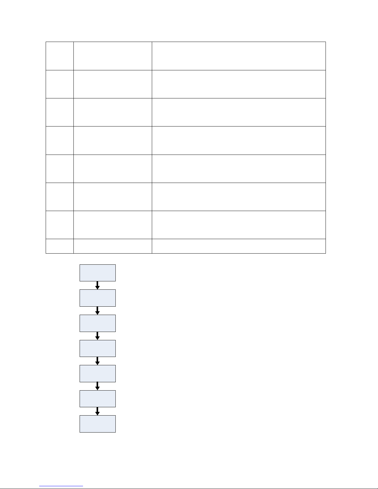
4.5.3 Operation Flow Chart
Set Pn-40 to 0
Set internal
speed command
by Pn-88~Pn-103
Set Pn-4 to 1
Set the
acceleration and
deceleration time
Host sends pulse
command for a
trial operation
⑴ Select speed control mode.
⑵ Select internal command as speed command by Pn-40.
⑶ Set the internal speed command.
⑷ Set Pn-34 for acceleration time and Pn-35 for deceleration time.
⑹ In no-load conition (leave the motor shaft free), send pulse command
for forward, reverse, acceleration / deceleration and other operation
for a trial operation.
Adjust the servo
gain
⑺ Make a trial processing and adjust the servo gain according to the
running status.
Set ServoEn ON
⑸ Set signal “ServoEn”ON or set Pn-8 to 100000, and the motor get the
power.
Pn-31
The first speed loop integral time
constant
The value is determined by the type of servo and the load condition. In general,
larger load inertia needs larger value. It can be switched with the second speed
loop integral time constant automatically or manually (refer to chapter 5 section
4.8).
Pn-32
The first low-pass bandwidth of
speed loop
Normally, smaller value results in slower and smoother speed response. But too
much small value may cause system oscillation. It can be switched with the
second low-pass bandwidth of speed loop automatically or manually (refer to
chapter 5 section 4.8).
Pn-33
The first low-pass filter
bandwidth of torque command
Normally, smaller value results in slower and smoother speed response. But
too much small value may cause system oscillation. It can be switched with the
second low-pass filter bandwidth of torque command automatically or
manually (refer to chapter 5 section 4.8).
Pn-36
The second speed loop
proportional gain
The value is determined by the type of servo and the load condition. In general,
larger load inertia needs larger value. It can be switched with the first speed
loop proportional gain automatically or manually (refer to chapter 5 section
4.8).
Pn-37
The second speed loop integral
time constant
The value is determined by the type of servo and the load condition. In general,
larger load inertia needs larger value. It can be switched with the first speed
loop integral time constant automatically or manually (refer to chapter 5 section
4.8).
Pn-38
The second low-pass bandwidth
of speed loop
Normally, smaller value results in slower and smoother speed response. But too
much small value may cause system oscillation. It can be switched with the first
low-pass bandwidth of speed loop automatically or manually (refer to chapter 5
section 4.8).
Pn-39
The second low-pass filter
bandwidth of torque command
Normally, smaller value results in slower and smoother speed response. But
too much small value may cause system oscillation. It can be switched with the
first low-pass filter bandwidth of torque command automatically or manually
(refer to chapter 5 section 4.8).
Pn-69
Enhancement of torque loop
response function
As set the value to 1, it can enhance the response of the torque, but it may cause
some current noise in the motor.
Page 30
29
BONMET motion GmbH/www.bonmet.com/www.bonmet.de
4.5.4 Function
1. Acceleration / deceleration time setting(Related parameters: Pn-34,Pn-35)
⑴
In case of overloading, it is suggested to set the acceleration / deceleration time to avoid the impact of the
instantaneous large current to avoid error or failure.
⑵ Set the value of Pn-34 for acceleration time constant while Pn-35 for deceleration time constant, the unit is ms.
4.6 Pulse Speed Control Mode
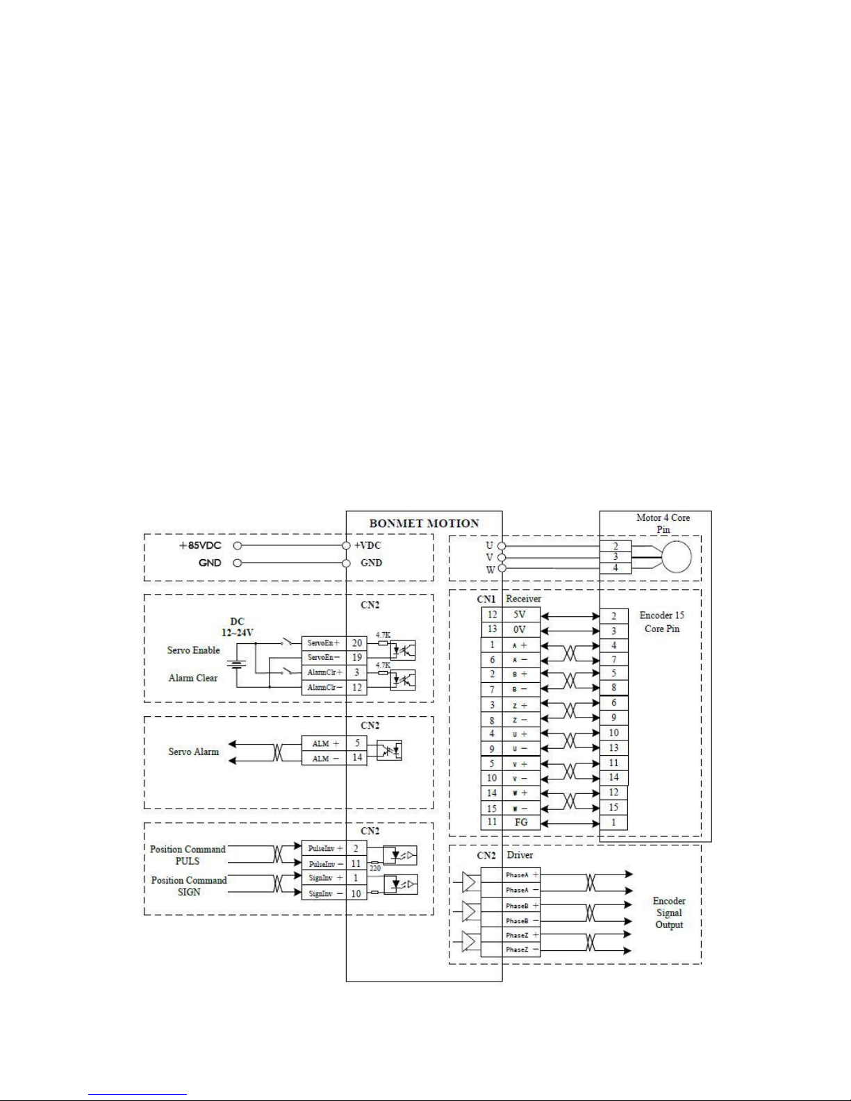
● Three type optional input pulse command(pulse/direction pulse, CCW/CW pulse, A phase/B phase pulse )
● Two types of input signal optional(open collector signal、differential signal)
● Optional electric gears
● Speed limitation and torque limitation can be set
4.6.1 Terminal Diagram
Page 31
30
BONMET motion GmbH/www.bonmet.com/www.bonmet.de
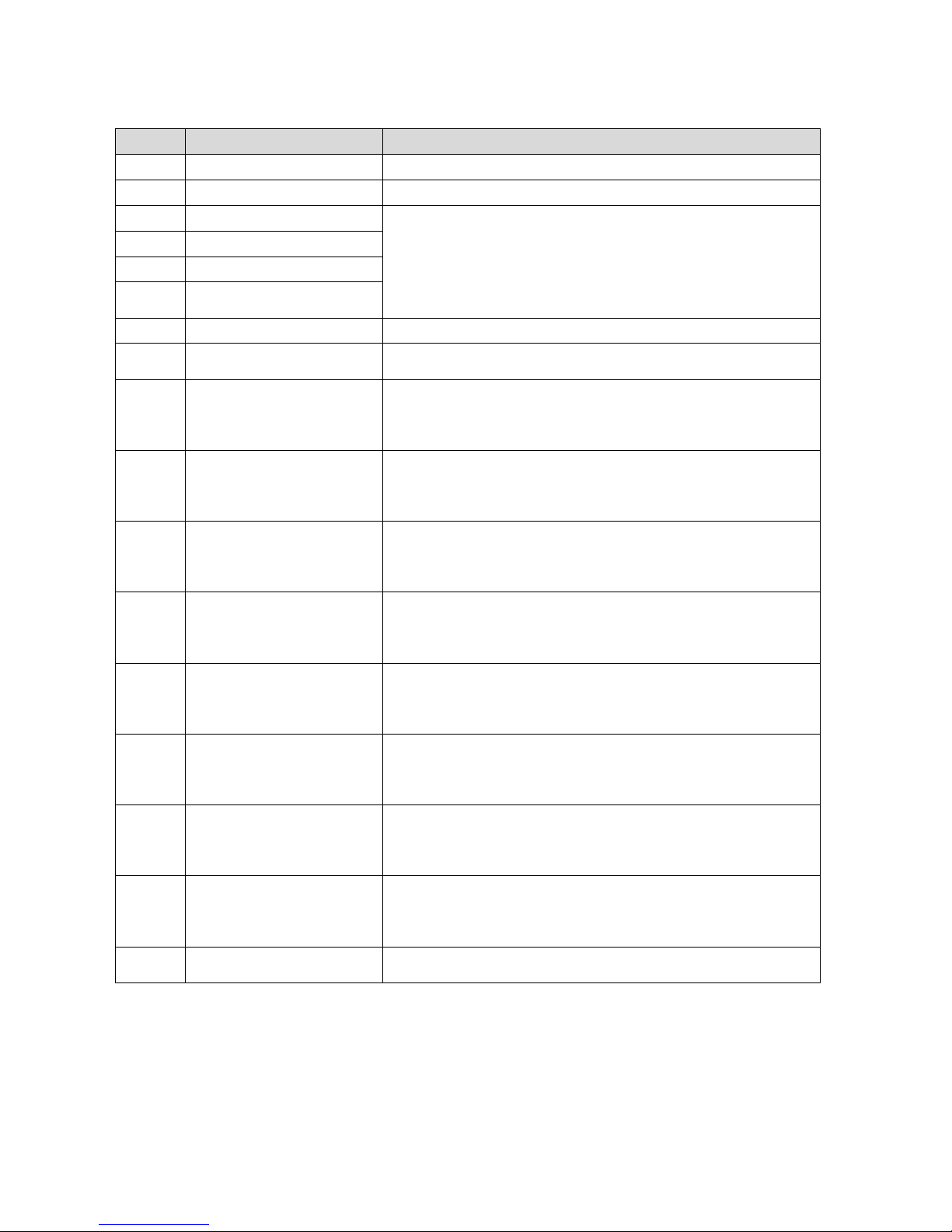
4.6.2 Parameters Setting
No.
Parameter
Function
Pn-4
Motor control mode
Select speed control mode(Value: 1)
Pn-40
Command type of speed control
Select command type.(Value: 2)
Pn-48
Denominator of electric gear
Two sets of electronic gear can be switched by the external trigger signal.
Pn-49
Numerator 1 of electric gear
Pn-50
Numerator 2 of electric gear
Pn-51
Dynamic electronic gear function
enable
Pn-52
Input pulse command mode
Select the pulse command type.
Pn-53
Invert direction of pulse
command
The direction of position command can be inverted with this function.
Pn-30
The first speed loop proportional
gain
The value is determined by the type of servo and the load condition. In general,
larger load inertia needs larger value. It can be switched with the second speed
loop proportional gain automatically or manually (refer to chapter 5 section
4.8).
Pn-31
The first speed loop integral time
constant
The value is determined by the type of servo and the load condition. In general,
larger load inertia needs larger value. It can be switched with the second speed
loop integral time constant automatically or manually (refer to chapter 5 section
4.8).
Pn-32
The first low-pass bandwidth of
speed loop
Normally, smaller value results in slower and smoother speed response. But too
much small value may cause system oscillation. It can be switched with the
second low-pass bandwidth of speed loop automatically or manually (refer to
chapter 5 section 4.8).
Pn-33
The first low-pass filter
bandwidth of torque command
Normally, smaller value results in slower and smoother speed response. But
too much small value may cause system oscillation. It can be switched with the
second low-pass filter bandwidth of torque command automatically or
manually (refer to chapter 5 section 4.8).
Pn-36
The second speed loop
proportional gain
The value is determined by the type of servo and the load condition. In general,
larger load inertia needs larger value. It can be switched with the first speed
loop proportional gain automatically or manually (refer to chapter 5 section
4.8).
Pn-37
The second speed loop integral
time constant
The value is determined by the type of servo and the load condition. In general,
larger load inertia needs larger value. It can be switched with the first speed
loop integral time constant automatically or manually (refer to chapter 5 section
4.8).
Pn-38
The second low-pass bandwidth
of speed loop
Normally, smaller value results in slower and smoother speed response. But too
much small value may cause system oscillation. It can be switched with the first
low-pass bandwidth of speed loop automatically or manually (refer to chapter 5
section 4.8).
Pn-39
The second low-pass filter
bandwidth of torque command
Normally, smaller value results in slower and smoother speed response. But
too much small value may cause system oscillation. It can be switched with the
first low-pass filter bandwidth of torque command automatically or manually
(refer to chapter 5 section 4.8).
Pn-69
Enhancement of torque loop
response function
As set the value to 1, it can enhance the response of the torque, but it may cause
some current noise in the motor.
Page 32
31
BONMET motion GmbH/www.bonmet.com/www.bonmet.de
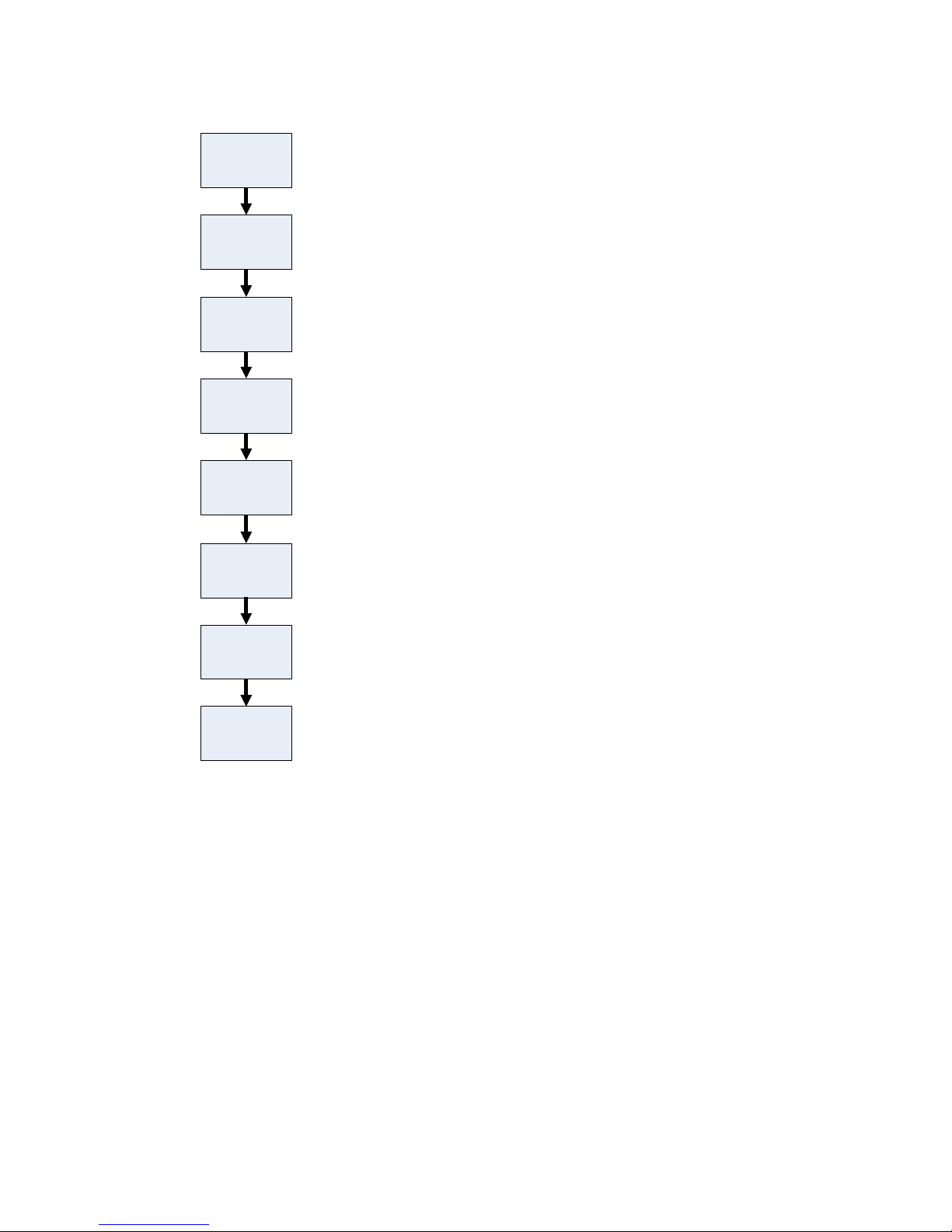
4.6.3 Operation Flow Chart
4.6.4 Function
1. Acceleration / deceleration time setting(Related parameters: Pn-34,Pn-35)
⑴
In case of overloading, it is suggested to set the acceleration / deceleration time to avoid the impact of the
instantaneous large current to avoid error or failure.
⑵ Set the value of Pn-34 for acceleration time constant while Pn-35 for deceleration time constant, the unit is ms.
Set Pn-40 to 2
Select input
pulse command
type
Set Pn-4 to 1
Select rotation
direction
Host sends pulse
command for a
trial operation
⑴ Select speed control mode.
⑵ Select pulse command as speed command by Pn-40.
⑶ Select input pulse command type (support pulse/direction pulse ,
CCW/CW pulse, A phase/B phase pulse ) by Pn-52.
⑷ Select rotation direction by Pn-53.
⑺ In no-load conition (leave the motor shaft free), send pulse command
for forward, reverse, acceleration / deceleration and other operation
for a trial operation.
Adjust the servo
gain
⑻ Make a trial processing and adjust the servo gain according to the
running status.
Set ServoEn ON
⑹ Set signal “ServoEn”ON or set Pn-8 to 100000, and the motor get the
power.
Select electronic
gear function
⑸ Select electronic gear ratio by Pn-48, Pn-49, Pn-50.
Page 33
32
BONMET motion GmbH/www.bonmet.com/www.bonmet.de
4.7 Analog Torque Control Mode
● ±10V Analog input
● Analog input drift compensation function
● Control through the I / O port, switching the rotation direction by digital input terminal
● Speed limitation and torque limitation can be set
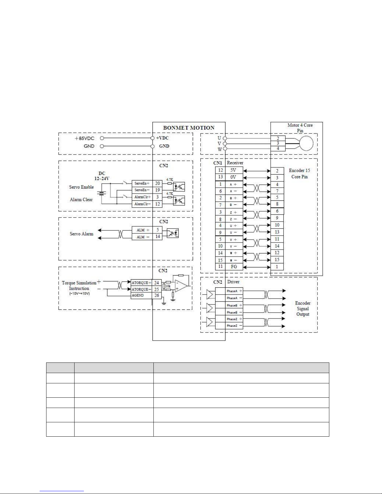
4.7.1 Terminal Diagram
4.7.2 Parameters Setting
No.
Parameter
Function
Pn-4
Motor control mode
Select torque control mode(Value: 0)
Pn-15
Gain of analog torque command
input
Set the ratio between the input voltage of analog torque and actual motor torque
Pn-16
Analog input drift compensation
The zero-bias compensation for the analog torque input.
Pn-17
Direction inversion of analog
speed input
Set the rotation direction.(Effective in analog torque mode)
Pn-42
Speed limit
Limit the maximum speed in torque control mode to avoid overspeed when the
motor is unloaded, parameter unit is rpm.
Page 34
33
BONMET motion GmbH/www.bonmet.com/www.bonmet.de
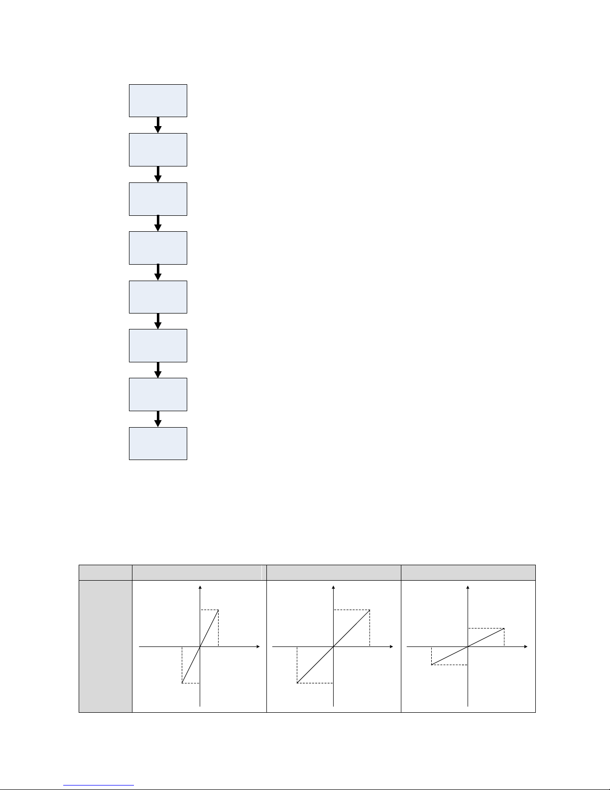
4.7.3 Operation Flow Chart
Figure 5-22 Operation Flow Chart
4.7.4 Function
1. Analog gain setting function(Related parameters:Pn-15)
Set the ratio between the input voltage of analog torque and actual motor torque.,they are proportional
relationship.
Value of Pn-15=(Max. input/Max. torque command)10。The default value is 100,which means 10Vsupport 100%
torque.
Item
Pn-15=50
Pn-15=100
Pn-15=200
Relationship
of input
voltage and
output
torque
Set analog gain
of torque control
by Pn-15
Select rotation
direction
Set Pn-4 to 0
Set the speed
limit in torque
control mode
⑴ Select torque control mode.
⑵ Set the analog gain to select the relationship between analog voltage
and torque command, 100% output torque according to 10V for default.
⑶ Select rotation direction by Pn-17 or switch the direction by digital
input “Logic_STOrder_Invert”
⑷ Set the speed limit in torque control mode by Pn-42.
Analog input
drift
compensation
⑹ Set parameter Pn-16 to clear the analog input drift.
Host sends pulse
command for a
trial operation
⑺ In no-load conition (leave the motor shaft free), send pulse command
for forward, reverse, acceleration / deceleration and other operation
for a trial operation.
Adjust the servo
gain
⑻ Make a trial processing and adjust the servo gain according to the
running status.
Set ServoEn ON
⑸ Set signal “ServoEn”ON or set Pn-8 to 100000, and the motor get
the power.
100%
+5V
-100%
-5V
0V
Torque command
Analog
voltage
100%
+10V
-100%
-10V
0V
Torque command
Analog
voltage
50%
+10V
-50%
-10V
0V
Torque command
Analog
voltage
Page 35
34
BONMET motion GmbH/www.bonmet.com/www.bonmet.de
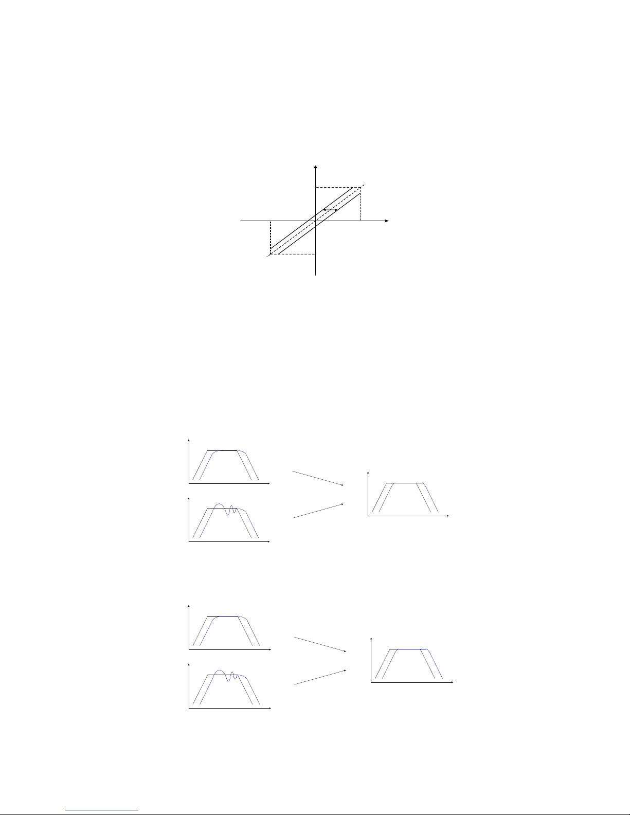
2. Analog compensation function(Related parameters:Pn-16)
● Customers can use the analog input drift compensation function to deal with the analog input drift.
⑴ Make a correct wiring and set the analog voltage to 0V.
⑵
Check the output torque by the drive monitor functions, adjust the value of the parameter Pn-16 to compensate.
As the zero-drift torque is a positive value, the parameter should be set a positive value; while the zero-drift torque
is a negative value, the parameter should be set a negative value.
Figure 5-23
4.8 Gain Adjustment
● The purpose of adjusting the servo system is to minimize the level of inaccuracy of the servo motor when
operating under instructions and also shorten the time of travel. Doing so needs to adjust gain parameter and
compensation parameter.
● The wrong parameter settings may lead to equipment failure and accidents, users should confirm the
correctness of the parameters before operation.
● It is suggested that operate without load for testing firstly.
1. Speed adjust
Figure 5-40
2. Position adjust
Figure 5-41
+10V-10V
0V
Max. torque in
positive direction
Max. torque in
nagetive direction
Speed
Time
Speed
Time
Speed
Time
Adjustment for
l
ag
ging
Adjustment for
overshoot
ing
Position
Time
Position
Time
Position
Time
Adjustment for
l
ag
ging
Adjustment for
overshoot
ing
Page 36

35
BONMET motion GmbH/www.bonmet.com/www.bonmet.de
3. Function
■ Speed loop gain(KP_S; Related parameters: Pn-30,Pn-36)
The larger the value is, the greater the stiffness would be. The value is determined by the type of servo and the
load condition. In general, larger load inertia needs larger value. If there is no oscillation, the larger the value
is the better the servo system performs.
■ Speed loop integral time constant(TC_S; Related parameters: Pn-31, Pn-37)
The smaller the value is, the greater the stiffness is. The value is determined by the type of servo and the load
condition. In general, larger load inertia needs larger value. Set the parameter as small as possible without
oscillation.
■ Low-pass bandwidth of speed loop(LFP_S; Related parameters: Pn-32, Pn-38)
Normally, smaller value results in slower and smoother speed response. Too small value may cause system
oscillation.
■ Low-pass filter bandwidth of torque command(LFP_C; Related parameters: Pn-33, Pn-39)
Normally, smaller value results in slower and smoother speed response. But too much small value may
cause system oscillation.
■ Position loop proportional gain(KP_P; Related parameters: Pn-44,Pn-66)
Higher gain results in greater mechanical stiffness and less position tracking error. Too large value may cause
overshoot or oscillation. The value is determined by the type and the load of servo drive.
■ Position loop differential proportional gain(Kd; Related parameters: Pn-45,Pn-67)
Higher gain results in greater mechanical stiffness and less position tracking error. Too big value may cause
overshoot or oscillation; This parameter is usually set to zero unless very fast response is required
■ The cut-off frequency of position feed forward filter(FLFP_P; Related parameters: Pn-46,Pn-68)
The filter is used to increase the stability of compound position control. Normally, users do not need to
change the default value.
■ Enhancements of the current loop response(Pn-69)
As requiring higher response, users can use this function to enhance current loop response by set Pn-69 to 1.
It will enhance the stiffness of the motor and may cause some noise.
Page 37
36
BONMET motion GmbH/www.bonmet.com/www.bonmet.de
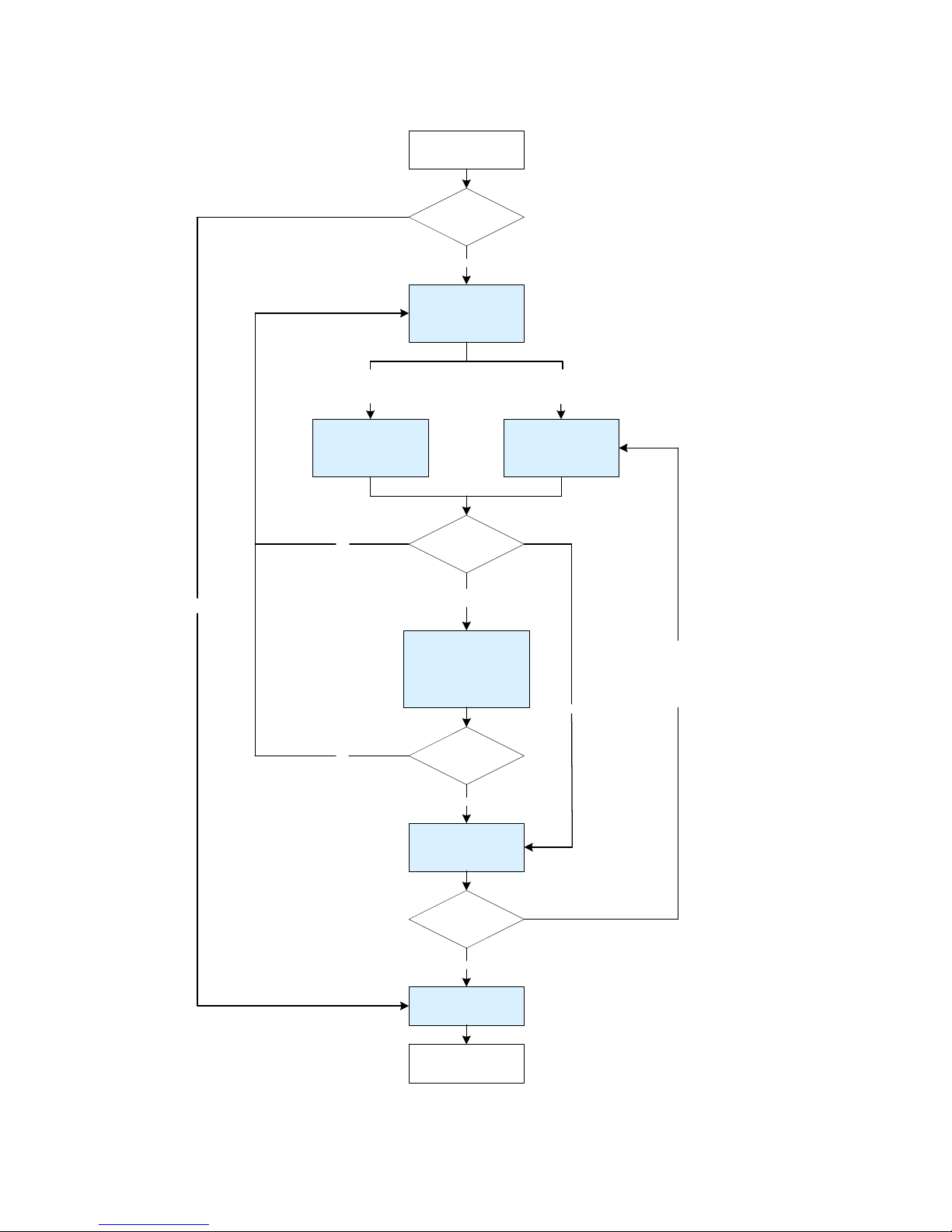
4. Adjust operation
Note: in speed control mode, customers just need to adjust speed gain.
Start operation
Reduce KP_P
(Pn44),general
300~500
Runs well
Rise KP_S(Pn30) and
reduce TC_S(PN31)
Reduce KP_S(Pn30) and
rise TC_S(PN31)
Reduce LFP_S(Pn32)
and LFP_C(Pn33), the
value of LFP_C(Pn33)
should be larger than
LFP_S(Pn32)
The out put torque is not enough or
mot or r uns some time s fast and
sometimes slow
Motor runs with vibration,could trigger
the alarm ERR-6, ERR-10, ERR-13
Runs with noise
Rise KP_P(Pn44)
NO
Motor overshoot occurs (positioning
vibration) a n d i t is still unable to
meet the needs of system response,
the overshoot may trigger the alarm
ERR-6, ERR-10, ERR-13
NO
Noise die out
YES
Runs well
Runs well
YES
YES
NO
Save parameters
End
YES
Page 38
37
BONMET motion GmbH/www.bonmet.com/www.bonmet.de
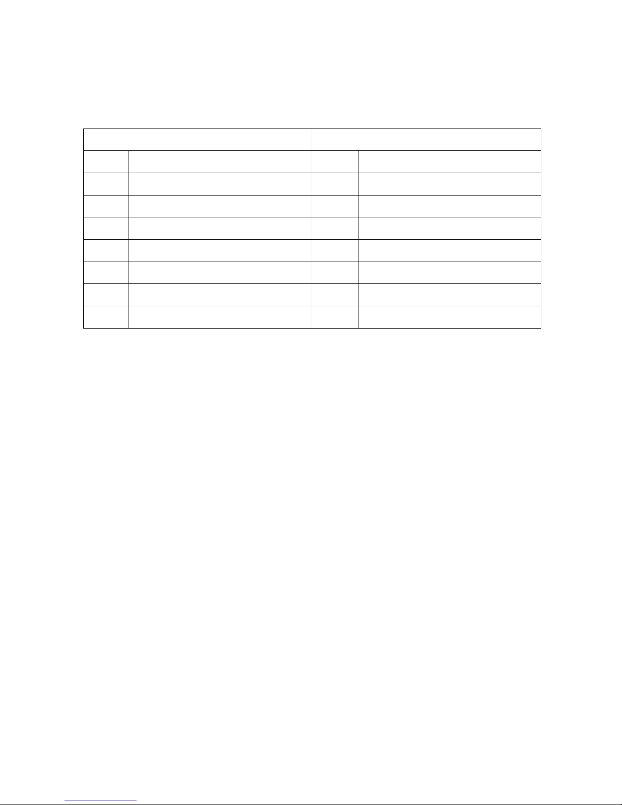
5. Gain switching function
BONMET servo drive support two sets PID parameters for gain switching function.
The first set of PID parameter
The second set of PID parameter
Number
Name
Number
Name
Pn-30
Speed loop proportional gain(PID1)
Pn-36
Speed loop proportional gain(PID2)
Pn-31
Speed loop integral time constant(PID1)
Pn-37
Speed loop integral time constant(PID2)
Pn-32
Low-pass bandwidth of speed loop(PID1)
Pn-38
Low-pass bandwidth of speed loop(PID2)
Pn-33
Low-pass filter bandwidth of torque command
(PID1)
Pn-39
Low-pass filter bandwidth of torque command
(PID2)
Pn-44
Position loop proportional gain(PID1)
Pn-66
Position loop proportional gain(PID2)
Pn-45
Position loop differential proportional gain
(PID1)
Pn-67
Position loop differential scale factor(PID2)
Pn-46
The cut-off frequency of position feed forward
filter(PID1)
Pn-68
The cut-off frequency of position feed forward
filter(PID2)
① Fixed to the first set of PID parameters.
Set Pn-64 to 0.
② Fixed to the second set of PID parameters.
Set Pn-64 to 1.
③ Switch the PID parameters by digital input. (NOT SUPPORT)
⑴ Set Pn-64 to 2 and build the mapping of the logic signal ―Logic_PID_Sel‖ and the physical digital input (refer
to chapter 5 section 5.16.5).
⑵ As ―Logic_PID_Sel‖ is OFF, the first set of PID parameters are valid, while as ―Logic_PID_Sel‖ is ON, the
second set of PID parameters are valid.
④ Switch the PID parameters by position deviation.
⑴ Set Pn-64 to 3 for switch mode, and set the trigger value by Pn-65.
⑵ As the position deviation value (position deviation value = pulse commands – feedback pulse, the unit is pulse)
is less than trigger value, the first set of PID parameters are valid, while as the position deviation value is larger
than trigger value, the second set of PID parameters are valid.
⑤ Switch the PID parameters by speed deviation.
⑴ Set Pn-64 to 4 for switch mode, and set the trigger value by Pn-65.
⑵ As the speed deviation value (speed deviation value = speed commands –motor speed, the unit is rpm) is less
than trigger value, the first set of PID parameters are valid, while as the speed deviation value is larger than trigger
value, the second set of PID parameters are valid.
⑥ Switch the PID parameters by motor speed.
⑴ Set Pn-64 to 5 for switch mode, and set the trigger value by Pn-65.
⑵ As the motor speed (the unit is rpm) is less than trigger value, the first set of PID parameters are valid, while as
the motor speed is larger than trigger value, the second set of PID parameters are valid.
⑦ Switch the PID parameters by motor output torque.
⑴ Set Pn-64 to 6 for switch mode, and set the trigger value by Pn-65.
⑵ As the motor output torque (the unit is %) is less than trigger value, the first set of PID parameters are valid,
while as the motor output torque is larger than trigger value, the second set of PID parameters are valid.
Page 39
38
BONMET motion GmbH/www.bonmet.com/www.bonmet.de
4.9 Overload Alarming Function
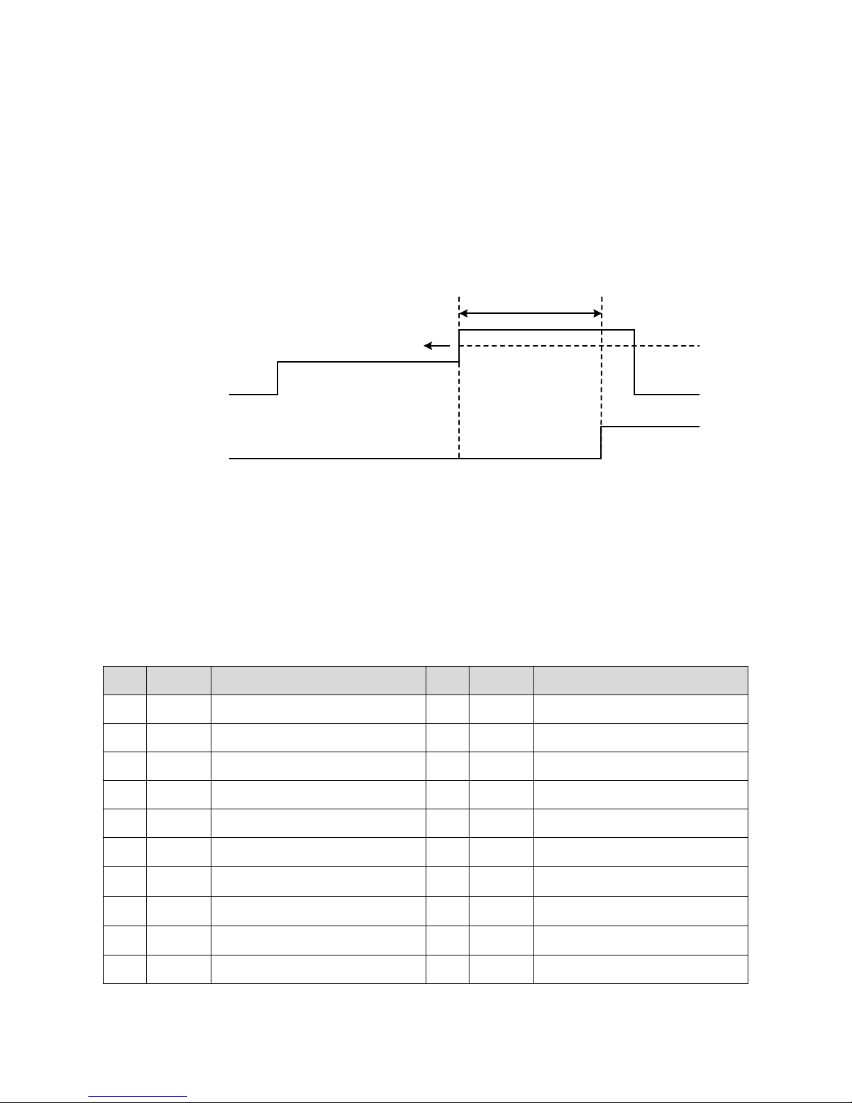
1. Function
When the motor output torque is over the alarming threshold value (Pn-22) and the last time is over the selected
testing time, the servo drive will alarm Err-18, the motor will stop.
2. Operation
⑴ Set the overload alarming threshold value by Pn-22
⑵ Set the overload testing time through by Pn-23
Figure 5-38 Overload alarming function
Chapter5 Parameters
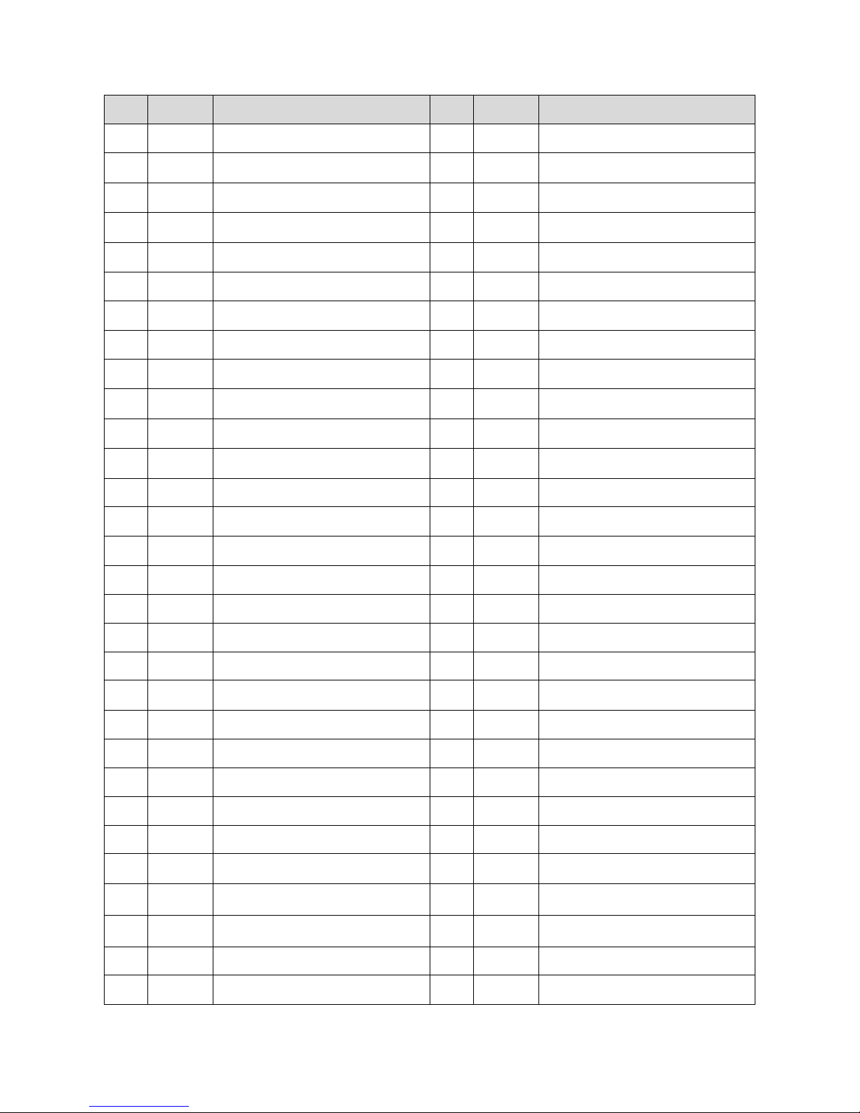
6.1 Parameter List
● The parameter “R-1”~“R-34” only can be modified by bus functions, can not be modified by panel.
● Control mode: ―ALL‖ means for the parameter is valid for all control mode, ―P‖ means for the parameter is
valid for position control mode, ―S‖ means for the parameter is valid for speed control mode, ―T‖ means for
the parameter is valid for torque control mode, ―SP‖ means for the parameter is valid for point to point control
mode, ―D‖ means for the parameter is valid for demo mode.
No.
Control
mode
Parameter
No.
Control
mode
Parameter
0
ALL
Firmware version
25
ALL
Internal torque limit in negative (CW)
direction
1
ALL
Motor type code
26
ALL
Internal torque limit in positive (CCW)
direction
2
ALL
User constants protection code
27
ALL
Torque limit mode
3
ALL
Drive status (Front Panel Display)
28
ALL
Notch function
4
ALL
Motor control mode
29
ALL
Notch frequency
5
ALL
Mechanical brake delay time
30
ALL
The first speed loop proportional gain
(PID1)
6
ALL
Current turn off delay time
31
ALL
The first speed loop integral time constant
(PID1)
7
ALL
Threshold speed of current turn off delay
time
32
ALL
The first low-pass bandwidth of speed
loop(PID1)
8
ALL
Anti-control of low-6-bit digital input
33
ALL
The first low-pass filter bandwidth of
torque command(PID1)
9
ALL
Anti-control of high-4-bit digital input
34 S Accelerationy time in speed control
Motor output torque 0% 50%
100%
Alarm output OFF
Alarm threshold value
(set by Pn-22)
Overload testing time
(set by Pn-23)
ON(ERR-18)
Page 40
39
BONMET motion GmbH/www.bonmet.com/www.bonmet.de
No.
Control
mode
Parameter
No.
Control
mode
Parameter
10
ALL
Anti-control of encoder feedback
35 S Deceleration time in speed control
11
ALL
Force-ON of low-6-bit digital input
36
ALL
The second speed loop proportional gain
(PID2)
12
ALL
Force-ON of high-4-bit digital input
37
ALL
The second speed loop integral time
constant(PID2)
13
ALL
Anti-control of high-4-bit digital output
38
ALL
The second low-pass bandwidth of speed
loop(PID2)
14
ALL
Anti-control of low-3-bit digital output
39
ALL
The second low-pass filter bandwidth of
torque command(PID2)
15 T Gain of analog torque command input
40 S Speed command mode
16
T
Analog input drift compensation of torque
command
41
S
Speed command in JOG control mode
(NOT SUPPORT)
17
T
Invert the direction of analog torque
command
42
ALL
Speed limit
18 S Gain of analog speed command input
43
S
Theshold value of speed reached output
(NOT SUPPORT)
19
S
Analog input drift compensation of speed
command
44
P
The first Position loop proportional gain
(PID1)
20
S
Invert the direction of analog speed
command
45
P
The first position loop differential
proportional gain(PID1)
21
S
Low-pass bandwidth of analog speed
input
46
P
The first cut-off frequency of position
feed forward filter(PID1)
22
ALL
Threshold value of torque overload alarm
47 P Constant of position command filter
23
ALL
Testing time of torque over load alarm
48
P,S
Denominator of electric gear ratio
24
ALL
Internal brake resistor temperature alarm
function(NOT SUPPORT)
49
P,S
Numerator 1 of electric gear ratio
50
P,S
Numerator 2 of electric gear ratio
81 D Internal torque command 10
51
P,S
Electric gear ratio switching function
82 D Internal torque command 11
52 P External pulse input type
83 D Internal torque command 12
53 P Invert of pulse command direction
84 D Internal torque command 13
54
P
Range of positioning complete function
(NOT SUPPORT)
85 D Internal torque command 14
55 P Position error detection range
86 D Internal torque command 15
56 P Position error detection function
87 D Internal torque command 16
57
ALL
Encoder output ratio(NOT SUPPORT)
88
S,D
Internal speed command 1
58
SP
Homing mode(NOT SUPPORT)
89
S,D
Internal speed command 2
59
SP
Homing speed(NOT SUPPORT)
90
S,D
Internal speed command 3
60
SP
Acceleration / deceleration in homing
operation(NOT SUPPORT)
91
S,D
Internal speed command 4
61
SP
High bit of home position offset(NOT
SUPPORT)
92
S,D
Internal speed command 5
62
SP
Low bit of home position offset(NOT
SUPPORT)
93
S,D
Internal speed command 6
63
SP,D
Demo or point to point mode selection
94
S,D
Internal speed command 7
64
ALL
Gain (PID) parameter switching mode
95
S,D
Internal speed command 8
Page 41
40
BONMET motion GmbH/www.bonmet.com/www.bonmet.de
No.
Control
mode
Parameter
No.
Control
mode
Parameter
65
ALL
Trigger value of gain (PID) parameter
switching function
96
S,D
Internal speed command 9
66
P
The second position loop proportional
gain(PID2)
97
S,D
Internal speed command 10
67
P
The second position loop differential
proportional gain(PID2)
98
S,D
Internal speed command 11
68
P
The second cut-off frequency of position
feed forward filter(PID2)
99
S,D
Internal speed command 12
69
ALL
Enhancement of torque loop response
function
100
S,D
Internal speed command 13
70 — Reservation
101
S,D
Internal speed command 14
71 — Reservation
102
S,D
Internal speed command 15
72 D Internal torque command 1
103
S,D
Internal speed command 16
73 D Internal torque command 2
104
SP,D
High bit of internal position command 1
74 D Internal torque command 3
105
SP,D
Low bit of internal position command 1
75 D Internal torque command 4
106
SP,D
Speed of internal position command 1
76 D Internal torque command 5
107
SP,D
Acceleration/deceleration of internal
position command 1
77 D Internal torque command 6
108
SP,D
Peak torque of internal position command
1
78 D Internal torque command 7
109
SP,D
High bit of internal position command 2
79 D Internal torque command 8
110
SP,D
Low bit of internal position command 2
80 D Internal torque command 9
111
SP,D
Speed of internal position command 2
112
SP,D
Acceleration/deceleration of internal
position command 2
143
SP,D
Peak torque of internal position command
8
113
SP,D
Peak torque of internal position command
2
144
SP,D
High bit of internal position command 9
114
SP,D
High bit of internal position command 3
145
SP,D
Low bit of internal position command 9
115
SP,D
Low bit of internal position command 3
146
SP,D
Speed of internal position command 9
116
SP,D
Speed of internal position command 3
147
SP,D
Acceleration/deceleration of internal
position command 9
117
SP,D
Acceleration/deceleration of internal
position command 3
148
SP,D
Peak torque of internal position command
9
118
SP,D
Peak torque of internal position command
3
149
SP,D
High bit of internal position command 10
119
SP,D
High bit of internal position command 4
150
SP,D
Low bit of internal position command 10
120
SP,D
Low bit of internal position command 4
151
SP,D
Speed of internal position command 10
121
SP,D
Speed of internal position command 4
152
SP,D
Acceleration/deceleration of internal
position command 10
122
SP,D
Acceleration/deceleration of internal
position command 4
153
SP,D
Peak torque of internal position command
10
123
SP,D
Peak torque of internal position command
4
154
SP,D
High bit of internal position command 11
124
SP,D
High bit of internal position command 5
155
SP,D
Low bit of internal position command 11
125
SP,D
Low bit of internal position command 5
156
SP,D
Speed of internal position command 11
Page 42
41
BONMET motion GmbH/www.bonmet.com/www.bonmet.de
No.
Control
mode
Parameter
No.
Control
mode
Parameter
126
SP,D
Speed of internal position command 5
157
SP,D
Acceleration/deceleration of internal
position command 11
127
SP,D
Acceleration/deceleration of internal
position command 5
158
SP,D
Peak torque of internal position command
11
128
SP,D
Peak torque of internal position command
5
159
SP,D
High bit of internal position command 12
129
SP,D
High bit of internal position command 6
160
SP,D
Low bit of internal position command 12
130
SP,D
Low bit of internal position command 6
161
SP,D
Speed of internal position command 12
131
SP,D
Speed of internal position command 6
162
SP,D
Acceleration/deceleration of internal
position command 12
132
SP,D
Acceleration/deceleration of internal
position command 6
163
SP,D
Peak torque of internal position command
12
133
SP,D
Peak torque of internal position command
6
164
SP,D
High bit of internal position command 13
134
SP,D
High bit of internal position command 7
165
SP,D
Low bit of internal position command 13
135
SP,D
Low bit of internal position command 7
166
SP,D
Speed of internal position command 13
136
SP,D
Speed of internal position command 7
167
SP,D
Acceleration/deceleration of internal
position command 13
137
SP,D
Acceleration/deceleration of internal
position command 7
168
SP,D
Peak torque of internal position command
13
138
SP,D
Peak torque of internal position command
7
169
SP,D
High bit of internal position command 14
139
SP,D
High bit of internal position command 8
170
SP,D
Low bit of internal position command 14
140
SP,D
Low bit of internal position command 8
171
SP,D
Speed of internal position command 14
141
SP,D
Speed of internal position command 8
172
SP,D
Acceleration/deceleration of internal
position command 14
142
SP,D
Acceleration/deceleration of internal
position command 8
173
SP,D
Peak torque of internal position command
14
174
SP,D
High bit of internal position command 15
R-10
ALL
FPGA version
175
SP,D
Low bit of internal position command 15
R-11
ALL
Index Reset Status
176
SP,D
Speed of internal position command 15
R-12
ALL
Index reset encoder counts
177
SP,D
Acceleration/deceleration of internal
position command 15
R-13
ALL
Real-time encoder counts
178
SP,D
Peak torque of internal position command
15
R-14
ALL
CN2 input terminal status
179
SP,D
High bit of internal position command 16
R-15
ALL
Encoder input terminal status
180
SP,D
Low bit of internal position command 16
R-16
ALL
CN2 output terminal status
181
SP,D
Speed of internal position command 16
R-17
ALL
The analog voltage of analog input port A
182
SP,D
Acceleration/deceleration of internal
position command 16
R-18
ALL
The analog voltage of analog input port B
183
SP,D
Peak torque of internal position command
16
R-19
ALL
DC bus voltage
184
ALL
Fieldbus selection
R-20
ALL
The current torque value
185
ALL
Modbus address
R-21
ALL
The current speed value
186
ALL
Modbus communication baud rate
R-22
ALL
The current high bit position value
187
ALL
Modbus communication frame type
R-23
ALL
The current low bit position value
Page 43
42
BONMET motion GmbH/www.bonmet.com/www.bonmet.de
No.
Control
mode
Parameter
No.
Control
mode
Parameter
188
ALL
CANOpen node ID(NOT SUPPORT)
R-24
ALL
Torque error value
189
ALL
CANOpen baud rate(NOT SUPPORT)
R-25
ALL
Speed error value
R-1
ALL
Index reset clear
R-26
ALL
High bit position error value
R-2
ALL
Operation command for EEPROM
R-27
ALL
Low bit position error value
R-3
ALL
Modbus synchronous command selection
R-28
ALL
Torque command
R-4 T Synchronous torque command
R-29
ALL
Speed command
R-5 S Synchronous speed command
R-30
ALL
High bit position command
R-6
P
High bit of synchronous position
command
R-31
ALL
Low bit position command
R-7
P
Low bit of synchronous position
command
R-32
ALL
Alarm code
R-8
ALL
Synchronous command enable
R-33
ALL
BootRom version
R-9
ALL
The implementation state of EEPROM
operation
R-34
ALL
Software version
6.2 Details
● ―RO‖ indicates read only, R/W indicates read and write, WC indicates write and clear.
Pn-0
Parameter
Firmware version
Modbus address
0x1C7D
Unit - Range
-
Default
-
CANbus object
-
Attrib
RO
Control mode:All
Details:Firmware verion of servo drive, can not be modified.
Pn-1
Parameter
Motor type code
Modbus address
0x1240
Unit - Range
0~21
Default
-
CANbus object
0x2240.0
Attrib
R/W
Control mode:All
Details:Motor type ccode, customers must ensure the motor type code is correct when restore the default parameters.
Code
Motor model
Code
Motor model
Code
Motor model
0
Factory parameters
8
SM110-060-30LFB
16
SM130-150-15LFB
1
SM80-013-30LFB
9
SM130-040-25LFB
17
SM130-150-25LFB
2
SM80-024-30LFB
10
SM130-050-25LFB
18
SM150-150-25LFB
3
SM80-033-30LFB
11
SM130-060-25LFB
19
SM150-180-20LFB
4
SM110-020-30LFB
12
SM130-077-20LFB
20
SM150-230-20LFB
5
SM110-040-30LFB
13
SM130-077-30LFB
21
SM150-270-20LFB
6
SM110-050-30LFB
14
SM130-100-15LFB
7
SM110-060-20LFB
15
SM130-100-25LFB
Pn-2
Parameter
User constants protection code
Modbus address
0x1241
Unit - Range
0~32767
Default
28977
CANbus object
0x2241.0
Attrib
R/W
Control mode:All
Details:It is used to prevent the parameters from being changed accidentally. The parameters can not be modified as the value is set
to any number except 28977.
Example:① After adjust the parameters, set Pn-2 to 28990,click ―Enter‖ button, then the other parameters can not be modified.
Page 44
43
BONMET motion GmbH/www.bonmet.com/www.bonmet.de
Change the parameter value and click “Enter” button, the decimal point does not disappear, the parameter can not be
modified.
The parameters can be modified as Pn-2 is set to 28977.
Pn-3
Parameter
Drive Status (Front Panel Display)
Modbus address
0x1242
Unit - Range
0~18
Default
0
CANbus object
0x2242.0
Attrib
R/W
Control mode:All(SDL10A drive, NOT SUPPORT)
Details:Select the information displaying on the panel, customers can find the details in chapter 4 section 4.2.2
Value
Display
Unit
Value
Display
Unit
0
Motor output torque (%)
%
10
Reservation
—
1
Motor speed (rpm)
rpm
11
Low 5 bit of position deviation
pulse
2
Low 5 bit of feedback pulse
pulse
12
High 5 bit of position deviation
pulse
3
High 5 bit of feedback pulse
pulse
13
Control mode
—
4
Torque command
%
14
Alarm display
—
5
Speed command
rpm
15
Low 4 bit of digital input status
—
6
Low 5 bit of position command
pulse
16
High 6 bit of digital input status
—
7
High 5 bit of position command
pulse
17
Digital output status
—
8
Motor current
Amp
18
Encoder input status
—
9
Absolute rotor position
pulse
Example:① The default value of Pn-3 is 0, it indicates the display will show the motor output torque (%).
② Set Pn-3 to 1, now the display will show motor speed (rpm).
Pn-4
Parameter
Motor control mode
Modbus address
0x1243
Unit - Range
0~7
Default
2
CANbus object
0x2243.0
Attrib
R/W
Control mode:All
Details:This parameter is used to select the control mode of servo drive, please refer to chapter 5 section 4.2~4.9 for details.
Value
Control mode
Function
0
Torque control mode
Control by analog command
1
Speed control mode
Control by internal command Control by analog command
Control by external pulse command
2
Position control mode
Control by external pulse command
3
JOG control mode
Control by panel (NOT SUPPORT)
4
Speed trial control mode
Control by internal command(NOT SUPPORT)
5
Analog input drift compensation
Used to analog input drift compensation function
Enter
Enter
Enter
Enter
Page 45
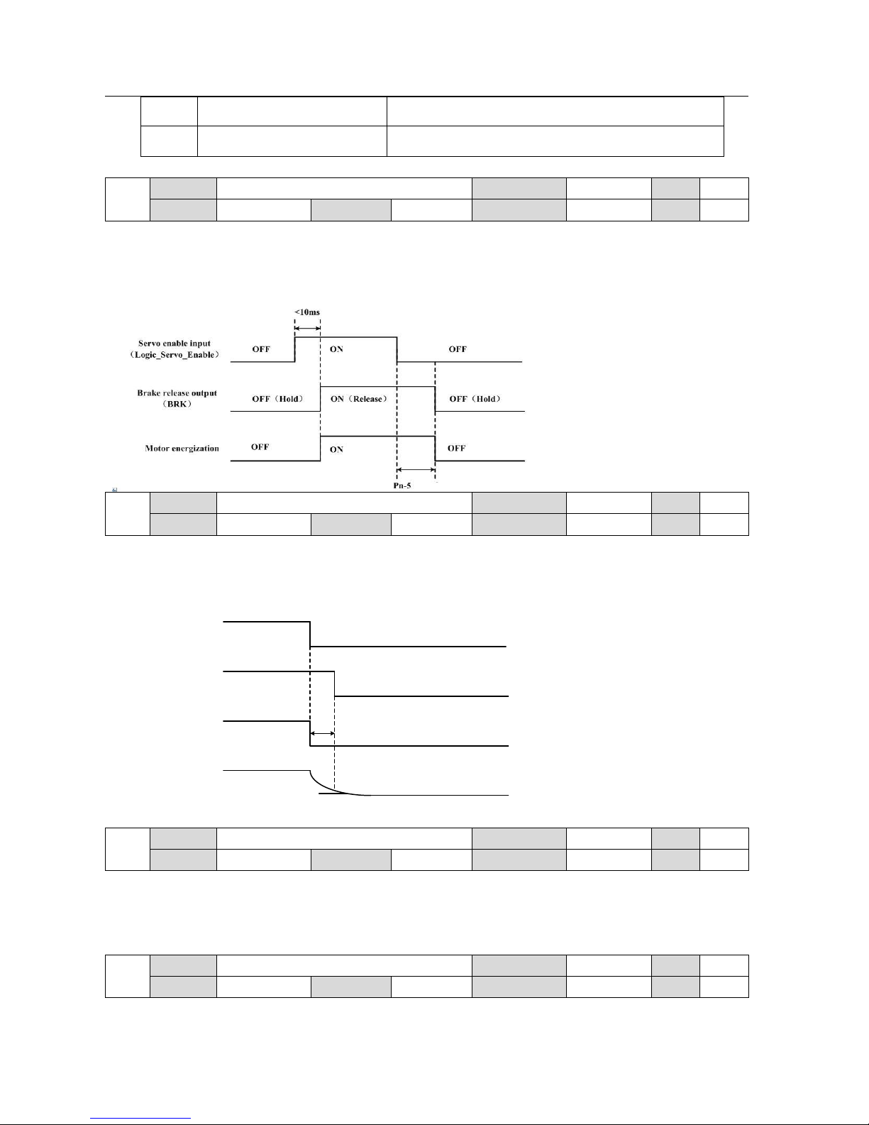
44
BONMET motion GmbH/www.bonmet.com/www.bonmet.de
6
Point-to-point control mode
Control by demo mode
7
Position/speed/torque control mode
Switch the control mode among position control, speed control
and torque control. (NOT SUPPORT)
Pn-5
Parameter
Mechanical brake delay time
Modbus address
0x1244
Unit
ms
Range
1~1000
Default
10
CANbus object
0x2244.0
Attrib
R/W
Control mode:All
Details:Set the delay time from the moment that ServoEn signal is OFF to the time mechanical brake available (output terminals
BRK changes from OFF to ON). This parameter should be bigger than mechanical braking delay time to avoid motor for
micro-displacement or falling.
Pn-6
Parameter
Current turn off delay time
Modbus address
0x1245
Unit
ms
Range
1~1000
Default
10
CANbus object
0x2245.0
Attrib
R/W
Control mode:All
Details:Customers can set up time from when detecting the off of Servo-ON input signal (Logic_Servo_Enable) is to when external
brake release signal (BRK-OFF) turns off, while the motor turns to servo off during the motor in motion.
The actual time is the minimum value between PN5 and the time speed falls to PN6.
Pn-7
Parameter
Threshold speed of current turn off delay time
Modbus address
0x1246
Unit
rpm
Range
1~6000
Default
30
CANbus object
0x2246.0
Attrib
R/W
Control mode:All
Details:Set up the speed timing of brake output checking during operation.
The actual time is the minimum value between PN5 and the time speed falls to PN6.
Pn-8
Parameter
Anti-control of low-6-bit digital input
Modbus address
0x1247
Unit
-
Range
0~63
Default
0
CANbus object
0x2247.0
Attrib
R/W
Control mode:All
ON
OFF
OFF
ON
OFF(Hold)ON(Release)
Delay time set
by Pn-6
Threshold speed
set by Pn-7
Motor speed
0rpm
Servo enable input
(Logic_Servo_Enable)
Motor energization
Brake release output
(BRK)
Page 46
45
BONMET motion GmbH/www.bonmet.com/www.bonmet.de
Details:This parameter is expressed by a 6-bit binary number. It is used for anti-control of low 6 bit digital input, “0” indicates
original state, and “1” indicates anti-control for this signal.
Note:This function is used for physical port anti-control operation, please refer to chapter 3 section 3.7.2 and chapter 5 section 5.16.5
for details of digital input/output function and mapping function.
Example:As the physical port status of “ServoEn” signal is OFF:
Item
Initial state
Anti-control operation
Parameter setting
Signal status
OFF
ON
Pn-9
Parameter
Anti-control of high-4-bit digital input
Modbus address
0x1248
Unit - Range
0~15
Default
0
CANbus object
0x2248.0
Attrib
R/W
Control mode:All
Details:This parameter is expressed by a 4-bit binary number. It is used for anti-control of high 4 bit digital input, “0” indicates
original state, and “1” indicates anti-control for this signal.
Note:
① This function is used for physical port anti-control operation, please refer to chapter 3 section 3.7.2 and chapter 5 section 5.16.5
for details of digital input/output function and mapping function.
② Please DO NOT take anti-control operation for “PulseInv” and “SignInv” signal for normal control, it may cause error.
Example:Please refer to the example of parameter “Pn-8”.
Pn-10
Parameter
Anti-control of encoder feedback
Modbus address
0x1249
Unit
-
Range
0~63
Default
0
CANbus object
0x2249.0
Attrib
R/W
Control mode:All
0位
0:Normal status
1:Anti-control operation
1位2位3位4位5位
CWTLtd
CCWTLtd
CWDis
CCWDis
AlarmClr
ServoEN
0:正常状态
1:对物理信号端口进行取反操作
PulseInv
SignInv
INH/SC2
CLE/SC1/ZEROSPD
0:Normal status
1:Anti-control operation
Bit 4 Bit 3 Bit 2 Bit 1
Page 47
46
BONMET motion GmbH/www.bonmet.com/www.bonmet.de
Details:This parameter is expressed by a 6-bit binary number. It is used for anti-control of of encoder feedback, “0” indicates
original state, and “1” indicates anti-control for this signal.
Note:Normally, we do not suggest customers to use this function.
Example:Please refer to the example of parameter “Pn-8”.
Pn-11
Parameter
Force-ON of low-6-bit digital input
Modbus address
0x124A
Unit - Range
0~63
Default
0
CANbus object
0x224A.0
Attrib
R/W
Control mode:All
Details:This parameter is expressed by a 6-bit binary number. It is used for force-ON control of low-6-bit digital input, “0”
indicates original state, and “1” indicates force-ON control for this signal. As if customers carry out the force-ON control, the
signal will stay “ON” status.
Note:This function is used for physical port force-ON control operation, please refer to chapter 3 section 3.7.2 and chapter 5 section
5.16.5 for details of digital input/output function and mapping function.
Example:As the physical port status of “ServoEn” signal is OFF:
Item
Initial state
Anti-control operation
Parameter setting
Signal status
OFF
ON
Pn-12
Parameter
Force-ON of high-2-bit digital input
Modbus address
0x124B
Unit - Range
0~3
Default
0
CANbus object
0x224B.0
Attrib
R/W
Control mode:All
Details:This parameter is expressed by a 2-bit binary number (“PulseInv” and “SignInv” can not be modified). It is used for
force-ON control of high-2-bit digital input, “0” indicates original state, and “1” indicates force-ON control for this signal. As if
0:正常状态
1:对物理信号端口进行取反操作
PhaseZ
PhaseB
PhaseA
PhaseW
PhaseV
PhaseU
0:Normal status
1:Anti-control operation
Bit 6 Bit 5 Bit 4 Bit 3 Bit 2 Bit 1
0:Normal status
1:Force-ON operation
Bit 6
CWTLtd
CCWTLtd
CWDis
CCWDis
AlarmClr
ServoEN
Bit 5 Bit 4 Bit 3 Bit 2 Bit 1
Page 48
47
BONMET motion GmbH/www.bonmet.com/www.bonmet.de
customers carry out the force-ON control, the signal will stay “ON” status.
Note:This function is used for physical port force-ON control operation, please refer to chapter 3 section 3.7.2 and chapter 5 section
5.16.5 for details of digital input/output function and mapping function.
Example:Please refer to the example of parameter “Pn-11”.
Pn-13
Parameter
Anti-control of high-4-bit digital output
Modbus address
0x124C
Unit - Range
0~15
Default
0
CANbus object
0x224C.0
Attrib
R/W
Control mode:All
Details:This parameter is expressed by a 4-bit binary number. It is used for anti-control of of digital output, “0” indicates original
state, and “1” indicates anti-control for this signal.
Note:As carry out anti-control of digital outputs, the signal status will change in very short time when power on, as the system reset.
Pn-14
Parameter
Anti-control of low-3-bit digital output
Modbus address
0x124D
Unit - Range
0~7
Default
0
CANbus object
0x224D.0
Attrib
R/W
Control mode:All
Details:This parameter is expressed by a 3-bit binary number. It is used for anti-control of of digital output, “0” indicates original
state, and “1” indicates anti-control for this signal.
Pn-15
Parameter
Gain of analog torque command input
Modbus address
0x124E
Unit - Range
10~300
Default
100
CANbus object
0x224E.0
Attrib
R/W
Control mode:Torque control mode
Details:This parameter is used to set the proportion relationship between analog torque input voltage and torque command.
Parameter value=(Max. input/Max. torque command)10。The default value is 100,which means 10Vsupport 100% torque.
Example:Please refer to chapter 5 section 5.7.4 for details.
0:正常状态
1:使物理信号端口强制为ON状态
INH/SC2
CLE/SC1/ZEROSPD
0:Normal status
1:Force-ON operation
Bit 2 Bit 1
0:正常状态
1:对物理信号端口进行取反操作
BRK
COIN
ALM
SRDY
0:Normal status
1:Anti-control operation
Bit 4 Bit 3 Bit 2 Bit 1
0:正常状态
1:对物理信号端口进行取反操作
PhaseZ
PhaseB
PhaseA
0:Normal status
1:Anti-control operation
Bit 3 Bit 2 Bit 1
Page 49
48
BONMET motion GmbH/www.bonmet.com/www.bonmet.de
Pn-16
Parameter
Analog input drift compensation of torque
command
Modbus address
0x124F
Unit
mV
Range
-30000~30000
Default
0
CANbus object
0x224F.0
Attrib
R/W
Control mode:Torque control mode
Details:This function is used to adjust the analog input drift compensation. As the zero-drift torque is a positive value, the parameter
should be set a positive value; while the zero-drift torque is a negative value, the parameter should be set a negative value.
Example:Please refer to chapter 5 section 5.7.4 for details.
Pn-17
Parameter
Invert the direction of analog torque command
Modbus address
0x1250
Unit - Range
0~1
Default
0
CANbus object
0x2250.0
Attrib
R/W
Control mode:Torque control mode
Details:The analog torque command is a vector parameter.
Set the parameter to 0, as if the input voltage is a positive voltage, the motor will run in positive direction, while the input voltage is a
negative voltage, the motor will run in negative direction.
Set the parameter to 1, as if the input voltage is a positive voltage, the motor will run in negative direction, while the input voltage is
a negative voltage, the motor will run in positive direction.
Pn-18
Parameter
Gain of analog speed command input
Modbus address
0x1251
Unit - Range
10~300
Default
100
CANbus object
0x2251.0
Attrib
R/W
Control mode:Speed control mode
Details:This parameter is used to set the proportion relationship between analog speed voltage and speed command.
Parameter value =(Max. input/Max. speed command)30000。The default value is 100,which means 10Vsupport speed command of
3000rpm.
Example:Please refer to chapter 5 section 5.4.4 for details.
Pn-19
Parameter
Analog input drift compensationof speed
command
Modbus address
0x1252
Unit
mV
Range
-30000~30000
Default
0
CANbus object
0x2252.0
Attrib
R/W
Control mode:Speed control mode
Details:This function is used to adjust the analog input drift compensation. As the zero-drift speed is a positive value, the parameter
should be set a positive value; while the zero-drift speed is a negative value, the parameter should be set a negative value.
Example:Please refer to chapter 5 section 5.4.4 for details.
Pn-20
Parameter
Invert the direction of analog speed command
Modbus address
0x1253
Unit - Range
0~1
Default
0
CANbus object
0x2253.0
Attrib
R/W
Control mode:Speed control mode
Details:The analog speed command is a vector parameter.
Set the parameter to 0, as if the input voltage is a positive voltage, the motor will run in positive direction, while the input voltage is a
negative voltage, the motor will run in negative direction.
Set the parameter to 1, as if the input voltage is a positive voltage, the motor will run in negative direction, while the input voltage is
a negative voltage, the motor will run in positive direction.
Pn-21
Parameter
Low-pass bandwidth of analog speed input
Modbus address
0x1254
Unit
Hz
Range
1~1000
Default
300
CANbus object
0x2254.0
Attrib
R/W
Control mode:Speed control mode
Details:This parameter is used to set the low-pass filter bandwidth of analog speed input. The greater the value is, it would bring
faster response of analog speed input and more signal noise; The smaller the value is, it would bring slower response of analog speed
input and less signal noise.
Page 50
49
BONMET motion GmbH/www.bonmet.com/www.bonmet.de
Pn-22
Parameter
Threshold value of torque overload alarm
Modbus address
0x1255
Unit % Range
1~400
Default
150
CANbus object
0x2255.0
Attrib
R/W
Pn-23
Parameter
Testing time of torque over load alarm
Modbus address
0x1256
Unit
ms
Range
1~32767
Default
100
CANbus object
0x2256.0
Attrib
R/W
Control mode:All
Details:These two parameters are used to for the torque overload function. As the motor output torque is over the threshold
value(Pn-22) for a period time over the testing time(Pn-23), the drive will alarm Err-18.
Pn-24
Parameter
Internal brake resistor temperature alarm function
Modbus address
0x1257
Unit - Range
0~1
Default
1
CANbus object
0x2257.0
Attrib
R/W
(NOT SUPPORT)
Pn-25
Parameter
Internal torque limit in negative (CW) direction
Modbus address
0x1258
Unit % Range
1 ~ 400
Default
300
CANbus object
0x2258.0
Attrib
R/W
Pn-26
Parameter
Internal torque limit in positive (CCW) direction
Modbus address
0x1259
Unit % Range
1 ~ 400
Default
300
CANbus object
0x2259.0
Attrib
R/W
Control mode:All
Details:These two parameters are used to set the torque limit in positive direction and negative direction, the motor output torque
will be limited under the parameter value.
Example:If customer want 2 times overload for the motor, which indicates that the max peak output will be 200% of motor norminal
torque, customer needs to set Pn-25 and Pn-26 to 200
Pn-27
Parameter
Torque limit mode
Modbus address
0x125A
Unit - Range
0~2
Default
0
CANbus object
0x225A.0
Attrib
R/W
Control mode:All
Details:This parameter is used for selecting the torque limit mode. Please refer to chapter 5 section 5.13 for details.
Parameter value
Control mode
Control mode
0
Internal torque limit
Set by parameters(Pn-25,Pn-26)
1
External torque limit
Switch the torque limit value(16 in all) from digital input(Pn72-~Pn-87)
2
Analog command torque limit
Limit the torque output by analog command
Pn-28
Parameter
Notch function
Modbus address
0x125B
Unit - Range
0~1
Default
0
CANbus object
0x225B.0
Attrib
R/W
Control mode:All
Details:This parameter is used to enable the notch function or not. Set it to 0, the notch function is valid; set it to 1, the notch
function is invalid.
Pn-29
Parameter
Notch frequency
Modbus address
0x125C
Unit - Range
0~3000
Default
1500
CANbus object
0x225C.0
Attrib
R/W
Control mode:All
Details:This parameter is used to set the notch frequency.
Page 51
50
BONMET motion GmbH/www.bonmet.com/www.bonmet.de
Pn-30
Parameter
The first speed loop proportional gain(PID1)
Modbus address
0x125D
Unit - Range
0~1000
Default
-
CANbus object
0x225D.0
Attrib
R/W
Control mode:All
Details:This parameter is used to set the first speed loop proportional gain, customers can switch it from the second speed loop
proportional gain, please refer to chapter 5 section 5.8 for gain switching function.
The larger the value is, the greater the stiffness would be. The value is determined by the type of servo and the load condition. In
general, larger load inertia needs larger value. If there is no oscillation, the higher the value is the better the servo system performs.
Note:For different motor, the default value is different.
Pn-31
Parameter
The first speed loop integral time constant(PID1)
Modbus address
0x125E
Unit - Range
1~8000
Default
-
CANbus object
0x225E.0
Attrib
R/W
Control mode:All
Details:This parameter is used to set the first speed loop integral time constant, customers can switch it from the second speed loop
proportional gain, please refer to chapter 5 section 5.8 for gain switching function.
The smaller the value, the greater the stiffness. The value is determined by the type of servo and the load condition. In general, larger
load inertia needs larger value. Set the parameter as small as possible without oscillation.
Note:For different motor, the default value is different.
Pn-32
Parameter
The first low-pass bandwidth of speed loop
(PID1)
Modbus address
0x125F
Unit
Hz
Range
1~1500
Default
400
CANbus object
0x225F.0
Attrib
R/W
Control mode:All
Details:This parameter is used to set the first low-pass bandwidth of speed loop, customers can switch it from the second speed loop
proportional gain, please refer to chapter 5 section 5.8for gain switching function.
Normally, smaller value results in slower and smoother speed response. Too small value may cause system oscillation.
Pn-33
Parameter
The first low-pass filter bandwidth of torque
command(PID1)
Modbus address
0x1260
Unit
Hz
Range
10~12000
Default
1000
CANbus object
0x2260.0
Attrib
R/W
Control mode:All
Details:This parameter is used to set the first low-pass filter bandwidth of torque command, customers can switch it from the second
speed loop proportional gain, please refer to chapter 5 section 5.8 for gain switching function.
Normally, smaller value results in slower and smoother speed response. But too much small value may cause system oscillation.
Pn-34
Parameter
Acceleration time in speed control
Modbus address
0x1261
Unit
10ms
Range
0~1000
Default
0
CANbus object
0x2261.0
Attrib
R/W
Pn-35
Parameter
Deceleration time in speed control
Modbus address
0x1262
Unit
10ms
Range
0~1000
Default
0
CANbus object
0x2262.0
Attrib
R/W
Control mode:Speed control mode
Details:These two parameters are used to set the acceleration time and deceleration time from 0rpm to 1000rpm.
Note:It is suggested that set Pn-34 and Pn-35 to 0 in position control mode.
Page 52
51
BONMET motion GmbH/www.bonmet.com/www.bonmet.de
Pn-36
Parameter
The second speed loop proportional gain(PID2)
Modbus address
0x1263
Unit - Range
1~1000
Default
-
CANbus object
0x2263.0
Attrib
R/W
Control mode:All
Details:This parameter is used to set the second speed loop proportional gain, customers can switch it from the first speed loop
proportional gain, please refer to chapter 5 section 5.8 for gain switching function.
The larger the value is, the greater the stiffness would be. The value is determined by the type of servo and the load condition. In
general, larger load inertia needs larger value. If there is no oscillation, the higher the value is the better the servo system performs.
Note:For different motor, the default value is different.
Pn-37
Parameter
The second speed loop integral time constant
(PID2)
Modbus address
0x1264
Unit
-
Range
1~8000
Default
-
CANbus object
0x2264.0
Attrib
R/W
Control mode:All
Details:This parameter is used to set the second speed loop integral time constant, customers can switch it from the first speed loop
proportional gain, please refer to chapter 5 section 5.8 for gain switching function.
The smaller the value, the greater the stiffness. The value is determined by the type of servo and the load condition. In general, larger
load inertia needs larger value. Set the parameter as small as possible without oscillation.
Note:For different motor, the default value is different.
Pn-38
Parameter
The second low-pass bandwidth of speed loop
(PID2)
Modbus address
0x1265
Unit
Hz
Range
1~1500
Default
400
CANbus object
0x2265.0
Attrib
R/W
Control mode:All
Details:This parameter is used to set the second low-pass bandwidth of speed loop, customers can switch it from the first speed loop
proportional gain, please refer to chapter 5 section 5.8 for gain switching function.
Normally, smaller value results in slower and smoother speed response. Too small value may cause system oscillation.
Pn-39
Parameter
The second low-pass filter bandwidth of torque
command(PID2)
Modbus address
0x1266
Unit
Hz
Range
10~12000
Default
1000
CANbus object
0x2266.0
Attrib
R/W
Control mode:All
Details:This parameter is used to set the second low-pass filter bandwidth of torque command, customers can switch it from the first
speed loop proportional gain, please refer to chapter 5 section 5.8 for gain switching function.
Normally, smaller value results in slower and smoother speed response. But too much small value may cause system oscillation.
Pn-40
Parameter
Speed command mode
Modbus address
0x1267
Unit - Range
0~2
Default
0
CANbus object
0x2267.0
Attrib
R/W
Control mode:Speed control mode
Details:This parameter is used to select the speed command mode.
Value
Control mode
Details
0
Internal speed control mode
Set speed command by 16 parameters(Pn88~Pn103), customers can
switch the speed command by digital input.
1
Analog speed control mode
Receive external analog command as speed command.
2
Pulse speed control mode
Receive external pulse command as speed command.
Page 53
52
BONMET motion GmbH/www.bonmet.com/www.bonmet.de
Pn-41
Parameter
Speed command in JOG control mode
Modbus address
0x1268
Unit
rpm
Range
0~3000
Default
1500
CANbus object
0x2268.0
Attrib
R/W
(NOT SUPPORT)
Pn-42
Parameter
Speed limit
Modbus address
0x1269
Unit
rpm
Range
0~6000
Default
-
CANbus object
0x2269.0
Attrib
R/W
Control mode:All
Details:This parameter is used to set the speed limit, it is valid in both direction.
Note:
① If the parameter value is larger than the motor nominal speed, the motor only can run at a speed no more than nominal speed.
② The default value is different for each motors, and the default value is the motor nominal speed.
Pn-43
Parameter
Threshold value of speed reached output
Modbus address
0x126A
Unit
rpm
Range
1~6000
Default
1500
CANbus object
0x226A.0
Attrib
R/W
(NOT SUPPORT)
Pn-44
Parameter
The first Position loop proportional gain(PID1)
Modbus address
0x126B
Unit - Range
1~32000
Default
-
CANbus object
0x226B.0
Attrib
R/W
Control mode:Position control mode
Details:This parameter is used to set the first position loop proportional gain, customers can switch it from the second speed loop
proportional gain, please refer to chapter 5 section 5.8 for gain switching function.
Higher gain results in greater mechanical stiffness and less position tracking error. Too large value may cause overshoot or
oscillation.
Note:For different motor, the default value is different.
Pn-45
Parameter
The first position loop differential proportional
gain(PID1)
Modbus address
0x126C
Unit
-
Range
0~300
Default
0
CANbus object
0x226C.0
Attrib
R/W
Control mode:Position control mode
Details:This parameter is used to set the first position loop differential proportional gain, customers can switch it from the second
speed loop proportional gain, please refer to chapter 5 section 5.8 for gain switching function.
Higher gain results in greater mechanical stiffness and less position tracking error. Too big value may cause overshoot or oscillation.
Note:This parameter is usually set to zero unless customers need very fast response.
Pn-46
Parameter
The first cut-off frequency of position feed
forward filter(PID1)
Modbus address
0x126D
Unit
Hz
Range
1~1000
Default
400
CANbus object
0x226D.0
Attrib
R/W
Control mode:Position control mode
Details:This parameter is used to set the first cut-off frequency of position feed forward filter, the unit is Hz.
Customers can switch it from the second speed loop proportional gain, please refer to chapter 5 section 5.8 for gain switching
function. The filter is used to increase the stability of compound position control.
Page 54
53
BONMET motion GmbH/www.bonmet.com/www.bonmet.de
Pn-47
Parameter
Constant of position command filter
Modbus address
0x126E
Unit
ms
Range
0~1000
Default
0
CANbus object
0x226E.0
Attrib
R/W
Control mode:Position control mode
Details:Smoothen filter for the command pulse with accelerate of index form, the value stands for time constant. The unit is ms;
Filter would not lose input pulse but may lead to delay. Filter is inactive as set to 0.
The filter works in the follow conditions:
● Host controller has not acceleration and deceleration function;
● Larger electronic gear ratio (>10);
● Lower command frequency;
● Motor running with jumps or other unstable conditions;
Pn-48
Parameter
Denominator of electric gear ratio
Modbus address
0x126F
Unit - Range
1~30000
Default
20
CANbus object
0x226F.0
Attrib
R/W
Pn-49
Parameter
Numerator 1 of electric gear ratio
Modbus address
0x1270
Unit - Range
1~30000
Default
20
CANbus object
0x2270.0
Attrib
R/W
Pn-50
Parameter
Numerator 2 of electric gear ratio
Modbus address
0x1271
Unit - Range
1~30000
Default
20
CANbus object
0x2271.0
Attrib
R/W
Pn-51
Parameter
Electric gear ratio switching function
Modbus address
0x1272
Unit - Range
0~1
Default
0
CANbus object
0x2272.0
Attrib
R/W
Control mode:Position control mode,Speed control mode
Details:These parameters are used for the electric gear ratio function in position control mode or external speed control mode by
Pn-48, Pn-49, Pn-50.
Note:Please refer to chapter 5 section 5.2.4 for details.
Pn-52
Parameter
External pulse input type
Modbus address
0x1273
Unit - Range
0~2
Default
0
CANbus object
0x2273.0
Attrib
R/W
Control mode:Position control mode,Speed control mode
Details:This parameter is used to set the pulse input command type:
Value
Pulse type
0
Pulse + direction pulse
1
CCW+CW pulse
2
A /B phase pulse
Pn-53
Parameter
Invert of pulse command direction
Modbus address
0x1274
Unit - Range
0~1
Default
0
CANbus object
0x2274.0
Attrib
R/W
Control mode:Position control mode,Speed control mode
Details:This function is used to set the inverting function of pulse command direction. “0” indicates normal direction while “1”
indicates reverse the direction of pulse command.
Pn-54
Parameter
Range of positioning complete function
Modbus address
0x1275
Unit
pulse
Range
0~30000
Default
1
CANbus object
0x2275.0
Attrib
R/W
(NOT SUPPORT)
Page 55
54
BONMET motion GmbH/www.bonmet.com/www.bonmet.de
Pn-55
Parameter
Position error detection range
Modbus address
0x1276
Unit
pulse
Range
1~30000
Default
400
CANbus object
0x2276.0
Attrib
R/W
Control mode:Position control mode
Details: This parameter is used to set the position error detection range. The threshold alarm value = the value of Pn-55 *100pulse,
as the position deviation counting pulse is over the threshold alarm value, the servo drive will alarm ERR-16
Note:Please refer to chapter 5 section 5.2.4 for details.
Pn-56
Parameter
Position error detection function
Modbus address
0x1277
Unit - Range
0~1
Default
1
CANbus object
0x2277.0
Attrib
R/W
Control mode:Position control mode
Details:This parameter is used to set enable the position error detection function. As set the parameter value to 0, the position error
detection function is valid; while set the parameter value to 1, the position error detection function is invalid.
Pn-57
Parameter
Encoder output ratio
Modbus address
0x1278
Unit - Range
1~1023
Default
33
CANbus object
0x2278.0
Attrib
R/W
(NOT SUPPORT)
Pn-58
Parameter
Homing mode
Modbus address
0x1279
Unit - Range
0~2
Default
0
CANbus object
0x2279.0
Attrib
R/W
(NOT SUPPORT)
Pn-59
Parameter
Homing speed
Modbus address
0x127A
Unit
rpm
Range
1~6000
Default
100
CANbus object
0x227A.0
Attrib
R/W
(NOT SUPPORT)
Pn-60
Parameter
Acceleration / deceleration in homing operation
Modbus address
0x127B
Unit
R / S2
Range
1~1000
Default
50
CANbus object
0x227B.0
Attrib
R/W
(NOT SUPPORT)
Pn-61
Parameter
High bit of home position offset
Modbus address
0x127C
Unit
pulse
Range
-30000~30000
Default
0
CANbus object
0x227C.0
Attrib
R/W
Pn-62
Parameter
Low bit of home position offset
Modbus address
0x127D
Unit
pulse
Range
-9999~9999
Default
0
CANbus object
0x227D.0
Attrib
R/W
(NOT SUPPORT)
Page 56
55
BONMET motion GmbH/www.bonmet.com/www.bonmet.de
Pn-63
Parameter
Demo or point to point mode selection
Modbus address
0x127E
Unit - Range
0~6
Default
2
CANbus object
0x227E.0
Attrib
R/W
Control mode:All
Details:This function is used to set the command type of demo mode or point to point mode.
Set the parameter value to 0, the drive will work in torque demo mode. From step 1 to 16(torque commands from parameters
Pn-72~ Pn-87), servo runs each step one by one and loops forever. In every step torque value and lasting time can be set
independently.
Set the parameter value to 1, the drive will work in speed demo mode. From step 1 to 16(speed commands from parameters
Pn-88~ Pn-103), servo runs each step one by one and loops forever. In every step torque value and lasting time can be set
independently.
Set the parameter value to 2, the drive will work in position demo mode, From step 1 to 16(position commands from parameters
Pn-104~ Pn-183), servo runs each step one by one and loops forever. In every step position, speed, acceleration and maximum torque
value can be set independently.
Pn-64
Parameter
Gain (PID) parameter switching mode
Modbus address
0x127F
Unit - Range
0~6
Default
0
CANbus object
0x227F.0
Attrib
R/W
Control mode:All
Details:This parameter is used to set the gain parameter switching mode.
Value
Switching mode
0
Fixed to the first set of PID parameters
1
Fixed to the second set of PID parameters
2
(NOT SUPPORT)
3
Switch the PID parameters by position deviation
4
Switch the PID parameters by speed deviation
5
Switch the PID parameters by motor speed
6
Switch the PID parameters by motor output torque
Note: Please refer to chapter 5 section 5.11 for details.
Pn-65
Parameter
Trigger value of gain (PID) parameter switching
function
Modbus address
0x1280
Unit
-
Range
0~32767
Default
0
CANbus object
0x2280.0
Attrib
R/W
Control mode:All
Details: This function is used to set the trigger value of gain parameter switching function, it is valid while set Pn-65 to 3/4/5/6.
② The parameter unit depends on Pn-64. As set Pn-65 to 3, the unit is pulse; set Pn-65 to 4 or 5, the unit is rpm; set Pn-65 to 6, the
unit is %.
Pn-66
Parameter
The second position loop proportional gain
(PID2)
Modbus address
0x1281
Unit
-
Range
1~32000
Default
1000
CANbus object
0x2281.0
Attrib
R/W
Control mode:Position control mode
Details:This parameter is used to set the second position loop proportional gain, customers can switch it from the second speed loop
proportional gain, please refer to chapter 5 section 5.11 for gain switching function.
Higher gain results in greater mechanical stiffness and less position tracking error. Too large value may cause overshoot or
oscillation.
Note:For different motor, the default value is different.
Page 57
56
BONMET motion GmbH/www.bonmet.com/www.bonmet.de
Pn-67
Parameter
The second position loop differential proportional
gain(PID2)
Modbus address
0x1282
Unit
-
Range
0~100
Default
0
CANbus object
0x2282.0
Attrib
R/W
Control mode:Position control mode
Details:Details:This parameter is used to set the second position loop differential proportional gain, customers can switch it from the
first speed loop proportional gain, please refer to chapter 5 section 5.11 for gain switching function.
Higher gain results in greater mechanical stiffness and less position tracking error. Too big value may cause overshoot or oscillation.
Note:This parameter is usually set to zero unless customers need very fast response.
Pn-68
Parameter
The second cut-off frequency of position feed
forward filter(PID2)
Modbus address
0x1283
Unit
Hz
Range
1~1000
Default
500
CANbus object
0x2283.0
Attrib
R/W
Control mode:Position control mode
Details:This parameter is used to set the second cut-off frequency of position feed forward filter, the unit is Hz.
Customers can switch it from the first speed loop proportional gain, please refer to chapter 5 section 5.11 for gain switching
function.The filter is used to increase the stability of compound position control.
Pn-69
Parameter
Enhancement of torque loop response function
Modbus address
0x1284
Unit - Range
0~1
Default
0
CANbus object
0x2284.0
Attrib
R/W
Control mode:All
Details:This parameter is used to enable the enhancement of torque loop response function. As set the parameter value to 1, the
torque loop response will be enhanced, but it may cause little current noise.
Pn-70
Parameter
Reservation
Modbus address
0x1285
Unit - Range
-
Default
-
CANbus object
0x2285.0
Attrib
R/W
Control mode:Reservation
Details:Reservation.
Pn-71
Parameter
Reservation
Modbus address
0x1286
Unit - Range
-
Default
-
CANbus object
0x2286.0
Attrib
R/W
Control mode:Reservation
Details:Reservation.
Pn-72
Parameter
Internal torque command 1
Modbus address
0x1287
Unit % Range
-400~400
Default
10
CANbus object
0x2287.0
Attrib
R/W
Control mode:Demo mode
Details:Internal torque command 1, the parameter value indicates the percentage of the nominal torque, the unit is %.
Pn-73
Parameter
Internal torque command 2
Modbus address
0x1288
Unit % Range
-400~400
Default
-10
CANbus object
0x2288.0
Attrib
R/W
Control mode:Demo mode
Details:Internal torque command 2, the parameter value indicates the percentage of the nominal torque, the unit is %.
Pn-74
Parameter
Internal torque command 3
Modbus address
0x1289
Unit % Range
-400~400
Default
20
CANbus object
0x2289.0
Attrib
R/W
Page 58
57
BONMET motion GmbH/www.bonmet.com/www.bonmet.de
Control mode:Demo mode
Details:Internal torque command 3, the parameter value indicates the percentage of the nominal torque, the unit is %.
Pn-75
Parameter
Internal torque command 4
Modbus address
0 x128A
Unit % Range
-400~400
Default
-20
CANbus object
0x228A.0
Attrib
R/W
Control mode:Demo mode
Details:Internal torque command 4, the parameter value indicates the percentage of the nominal torque, the unit is %.
Pn-76
Parameter
Internal torque command 5
Modbus address
0x128B
Unit % Range
-400~400
Default
30·
CANbus object
0x228B.0
Attrib
R/W
Control mode:Demo mode
Details:Internal torque command 5, the parameter value indicates the percentage of the nominal torque, the unit is %.
Pn-77
Parameter
Internal torque command 6
Modbus address
0x128C
Unit % Range
-400~400
Default
-30
CANbus object
0x228C.0
Attrib
R/W
Control mode:Demo mode
Details:Internal torque command 6, the parameter value indicates the percentage of the nominal torque, the unit is %.
Pn-78
Parameter
Internal torque command 7
Modbus address
0x128D
Unit % Range
-400~400
Default
40
CANbus object
0x228D.0
Attrib
R/W
Control mode:Demo mode
Details:Internal torque command 7, the parameter value indicates the percentage of the nominal torque, the unit is %.
Pn-79
Parameter
Internal torque command 8
Modbus address
0x128E
Unit % Range
-400~400
Default
-40
CANbus object
0x228E.0
Attrib
R/W
Control mode:Demo mode
Details:Internal torque command 8, the parameter value indicates the percentage of the nominal torque, the unit is %.
Pn-80
Parameter
Internal torque command 9
Modbus address
0x128F
Unit % Range
-400~400
Default
50
CANbus object
0x228F.0
Attrib
R/W
Control mode:Demo mode
Details:Internal torque command 9, the parameter value indicates the percentage of the nominal torque, the unit is %.
Pn-81
Parameter
Internal torque command 10
Modbus address
0x1290
Unit % Range
-400~400
Default
-50
CANbus object
0x2290.0
Attrib
R/W
Control mode:Demo mode
Details:Internal torque command 10, the parameter value indicates the percentage of the nominal torque, the unit is %.
Pn-82
Parameter
Internal torque command 11
Modbus address
0x1291
Unit % Range
-400~400
Default
60
CANbus object
0x2291.0
Attrib
R/W
Control mode:Demo mode
Details:Internal torque command 11, the parameter value indicates the percentage of the nominal torque, the unit is %.
Page 59
58
BONMET motion GmbH/www.bonmet.com/www.bonmet.de
Pn-83
Parameter
Internal torque command 12
Modbus address
0x1292
Unit % Range
-400~400
Default
-60
CANbus object
0x2292.0
Attrib
R/W
Control mode:Demo mode
Details:Internal torque command 12, the parameter value indicates the percentage of the nominal torque, the unit is %.
Pn-84
Parameter
Internal torque command 13
Modbus address
0x1293
Unit % Range
-400~400
Default
70
CANbus object
0x2293.0
Attrib
R/W
Control mode:Demo mode
Details:Internal torque command 13, the parameter value indicates the percentage of the nominal torque, the unit is %.
Pn-85
Parameter
Internal torque command 14
Modbus address
0x1294
Unit % Range
-400~400
Default
-70
CANbus object
0x2294.0
Attrib
R/W
Control mode:Demo mode
Details:Internal torque command 14, the parameter value indicates the percentage of the nominal torque, the unit is %.
Pn-86
Parameter
Internal torque command 15
Modbus address
0x1295
Unit % Range
-400~400
Default
80
CANbus object
0x2295.0
Attrib
R/W
Control mode:Demo mode
Details:Internal torque command 15, the parameter value indicates the percentage of the nominal torque, the unit is %.
Pn-87
Parameter
Internal torque command 16
Modbus address
0x1296
Unit % Range
-400~400
Default
-80
CANbus object
0x2296.0
Attrib
R/W
Control mode:Demo mode
Details:Internal torque command 16, the parameter value indicates the percentage of the nominal torque, the unit is %.
Pn-88
Parameter
Internal speed command 1
Modbus address
0x1297
Unit
rpm
Range
-6000~6000
Default
10
CANbus object
0x2297.0
Attrib
R/W
Control mode:Speed control mode,Demo mode
Details:Internal speed command 1,the unit is rpm.
Pn-89
Parameter
Internal speed command 2
Modbus address
0x1298
Unit
rpm
Range
-6000~6000
Default
20
CANbus object
0x2298.0
Attrib
R/W
Control mode:Speed control mode,Demo mode
Details:Internal speed command 2,the unit is rpm.
Pn-90
Parameter
Internal speed command 3
Modbus address
0x1299
Unit
rpm
Range
-6000~6000
Default
30
CANbus object
0x2299.0
Attrib
R/W
Control mode:Speed control mode,Demo mode
Details:Internal speed command 3,the unit is rpm.
Pn-91
Parameter
Internal speed command 4
Modbus address
0x129A
Unit
rpm
Range
-6000~6000
Default
40
CANbus object
0x229A.0
Attrib
R/W
Control mode:Speed control mode,Demo mode
Details:Internal speed command 4,the unit is rpm.
Page 60
59
BONMET motion GmbH/www.bonmet.com/www.bonmet.de
Pn-92
Parameter
Internal speed command 5
Modbus address
0x129B
Unit
rpm
Range
-6000~6000
Default
50
CANbus object
0x229B.0
Attrib
R/W
Control mode:Speed control mode,Demo mode
Details:Internal speed command 5,the unit is rpm.
Pn-93
Parameter
Internal speed command 6
Modbus address
0x129C
Unit
rpm
Range
-6000~6000
Default
60
CANbus object
0x229C.0
Attrib
R/W
Control mode:Speed control mode,Demo mode
Details:Internal speed command 6,the unit is rpm.
Pn-94
Parameter
Internal speed command 7
Modbus address
0x129D
Unit
rpm
Range
-6000~6000
Default
70
CANbus object
0x229D.0
Attrib
R/W
Control mode:Speed control mode,Demo mode
Details:Internal speed command 7,the unit is rpm.
Pn-95
Parameter
Internal speed command 8
Modbus address
0x129E
Unit
rpm
Range
-6000~6000
Default
80
CANbus object
0x229E.0
Attrib
R/W
Control mode:Speed control mode,Demo mode
Details:Internal speed command 8,the unit is rpm.
Pn-96
Parameter
Internal speed command 9
Modbus address
0x129F
Unit
rpm
Range
-6000~6000
Default
-10
CANbus object
0x229F.0
Attrib
R/W
Control mode:Speed control mode,Demo mode
Details:Internal speed command 9,the unit is rpm.
Pn-97
Parameter
Internal speed command 10
Modbus address
0x12A0
Unit
rpm
Range
-6000~6000
Default
-20
CANbus object
0x22A0.0
Attrib
R/W
Control mode:Speed control mode,Demo mode
Details:Internal speed command 10,the unit is rpm.
Pn-98
Parameter
Internal speed command 11
Modbus address
0x12A1
Unit
rpm
Range
-6000~6000
Default
-30
CANbus object
0x22A1.0
Attrib
R/W
Control mode:Speed control mode,Demo mode
Details:Internal speed command 11,the unit is rpm.
Pn-99
Parameter
Internal speed command 12
Modbus address
0x12A2
Unit
rpm
Range
-6000~6000
Default
-40
CANbus object
0x22A2.0
Attrib
R/W
Control mode:Speed control mode,Demo mode
Details:Internal speed command 12,the unit is rpm.
Pn-100
Parameter
Internal speed command 13
Modbus address
0x12A3
Unit
rpm
Range
-6000~6000
Default
-50
CANbus object
0x22A3.0
Attrib
R/W
Control mode:Speed control mode,Demo mode
Page 61
60
BONMET motion GmbH/www.bonmet.com/www.bonmet.de
Details:Internal speed command 13,the unit is rpm.
Pn-101
Parameter
Internal speed command 14
Modbus address
0x12A4
Unit
rpm
Range
-6000~6000
Default
-60
CANbus object
0x22A4.0
Attrib
R/W
Control mode:Speed control mode,Demo mode
Details:Internal speed command 14,the unit is rpm.
Pn-102
Parameter
Internal speed command 15
Modbus address
0x12A5
Unit
rpm
Range
-6000~6000
Default
-70
CANbus object
0x22A5.0
Attrib
R/W
Control mode:Speed control mode,Demo mode
Details:Internal speed command 15,the unit is rpm.
Pn-103
Parameter
Internal speed command 16
Modbus address
0x12A6
Unit
rpm
Range
-6000~6000
Default
-80
CANbus object
0x22A6.0
Attrib
R/W
Control mode:Speed control mode,Demo mode
Details:Internal speed command 16,the unit is rpm.
Pn-104
Parameter
High bit of internal position command 1
Modbus address
0x12A7
Unit
pulse
Range
-30000~30000
Default
50
CANbus object
0x22A7.0
Attrib
R/W
Pn-105
Parameter
Low bit of internal position command 1
Modbus address
0x12A8
Unit
pulse
Range
-9999~9999
Default
0
CANbus object
0x22A8.0
Attrib
R/W
Control mode:Point to point control mode,Demo mode
Details:Set position command 1 in point to point control mode or demo mode, the unit is pulse. The position command=high bit
part×10000+low bit part.
Pn-106
Parameter
Speed of internal position command 1
Modbus address
0x12A9
Unit
rpm
Range
1~6000
Default
2000
CANbus object
0x22A9.0
Attrib
R/W
Control mode:Point to point control mode,Demo mode
Details:Set the motor speed of internal position 1, the unit is rpm.
Pn-107
Parameter
Acceleration/deceleration of internal position
command 1
Modbus address
0x12AA
Unit
R / S2
Range
1~1000
Default
25
CANbus object
0x22AA.0
Attrib
R/W
Control mode:Point to point control mode,Demo mode
Details:Set the acceleration and deceleration of internal position command 1.
Pn-108
Parameter
Peak torque of internal position command 1
Modbus address
0x12AB
Unit
%
Range
0~400
Default
125
CANbus object
0x22AB.0
Attrib
R/W
Control mode:Point to point control mode,Demo mode
Details:Set the torque limit of internal position command 1, the unit is %.
Pn-109
Parameter
High bit of internal position command 2
Modbus address
0x12AC
Unit
pulse
Range
-30000~30000
Default
125
CANbus object
0x22AC.0
Attrib
R/W
Page 62
61
BONMET motion GmbH/www.bonmet.com/www.bonmet.de
Pn-110
Parameter
Low bit of internal position command 2
Modbus address
0x12AD
Unit
pulse
Range
-9999~9999
Default
0
CANbus object
0x22AD.0
Attrib
R/W
Control mode:Point to point control mode,Demo mode
Details:Set position command 2 in point to point control mode or demo mode, the unit is pulse. The position command=high bit
part×10000+low bit part.
Pn-111
Parameter
Speed of internal position command 2
Modbus address
0x12AE
Unit
rpm
Range
1~6000
Default
2000
CANbus object
0x22AE.0
Attrib
R/W
Control mode:Point to point control mode,Demo mode
Details:Set the motor speed of internal position 2, the unit is rpm.
Pn-112
Parameter
Acceleration/deceleration of internal position
command 2
Modbus address
0x12AF
Unit
R / S2
Range
1~1000
Default
25
CANbus object
0x22AF.0
Attrib
R/W
Control mode:Point to point control mode,Demo mode
Details:Set the acceleration and deceleration of internal position command 2.
Pn-113
Parameter
Peak torque of internal position command 2
Modbus address
0x12B0
Unit % Range
0~400
Default
125
CANbus object
0x22B0.0
Attrib
R/W
Control mode:Point to point control mode,Demo mode
Details:Set the torque limit of internal position command 2, the unit is %.
Pn-114
Parameter
High bit of internal position command 3
Modbus address
0x12B1
Unit
pulse
Range
-30000~30000
Default
90
CANbus object
0x22B1.0
Attrib
R/W
Pn-115
Parameter
Low bit of internal position command 3
Modbus address
0x12B2
Unit
pulse
Range
-9999~9999
Default
0
CANbus object
0x22B2.0
Attrib
R/W
Control mode:Point to point control mode,Demo mode
Details:Set position command 3 in point to point control mode or demo mode, the unit is pulse. The position command=high bit
part×10000+low bit part.
Pn-116
Parameter
Speed of internal position command 3
Modbus address
0x12B3
Unit
rpm
Range
1~6000
Default
2000
CANbus object
0x22B3.0
Attrib
R/W
Control mode:Point to point control mode,Demo mode
Details:Set the motor speed of internal position 3, the unit is rpm.
Pn-117
Parameter
Acceleration/deceleration of internal position
command 3
Modbus address
0x12B4
Unit
R / S2
Range
1~1000
Default
25
CANbus object
0x22B4.0
Attrib
R/W
Control mode:Point to point control mode,Demo mode
Details:Set the acceleration and deceleration of internal position command 3.
Pn-118
Parameter
Peak torque of internal position command 3
Modbus address
0x12B5
Unit
%
Range
0~400
Default
125
CANbus object
0x22B5.0
Attrib
R/W
Page 63
62
BONMET motion GmbH/www.bonmet.com/www.bonmet.de
Control mode:Point to point control mode,Demo mode
Details:Set the torque limit of internal position command 3, the unit is %.
Pn-119
Parameter
High bit of internal position command 4
Modbus address
0x12B6
Unit
pulse
Range
-30000~30000
Default
20
CANbus object
0x22B6.0
Attrib
R/W
Pn-120
Parameter
Low bit of internal position command 4
Modbus address
0x12B7
Unit
pulse
Range
-9999~9999
Default
0
CANbus object
0x22B7.0
Attrib
R/W
Control mode:Point to point control mode,Demo mode
Details:Set position command 4 in point to point control mode or demo mode, the unit is pulse. The position command=high bit
part×10000+low bit part.
Pn-121
Parameter
Speed of internal position command 4
Modbus address
0x12B8
Unit
rpm
Range
1~6000
Default
2000
CANbus object
0x22B8.0
Attrib
R/W
Control mode:Point to point control mode,Demo mode
Details:Set the motor speed of internal position 4, the unit is rpm.
Pn-122
Parameter
Acceleration/deceleration of internal position
command 4
Modbus address
0x12B9
Unit
R / S2
Range
1~1000
Default
25
CANbus object
0x22B9.0
Attrib
R/W
Control mode:Point to point control mode,Demo mode
Details:Set the acceleration and deceleration of internal position command 4.
Pn-123
Parameter
Peak torque of internal position command 4
Modbus address
0x12BA
Unit % Range
0~400
Default
125
CANbus object
0x22BA.0
Attrib
R/W
Control mode:Point to point control mode,Demo mode
Details:Set the torque limit of internal position command 4, the unit is %.
Pn-124
Parameter
High bit of internal position command 5
Modbus address
0x12BB
Unit
pulse
Range
-30000~30000
Default
50
CANbus object
0x22BB.0
Attrib
R/W
Pn-125
Parameter
Low bit of internal position command 5
Modbus address
0x12BC
Unit
pulse
Range
-9999~9999
Default
0
CANbus object
0x22BC.0
Attrib
R/W
Control mode:Point to point control mode,Demo mode
Details:Set position command 5 in point to point control mode or demo mode, the unit is pulse. The position command=high bit
part×10000+low bit part.
Pn-126
Parameter
Speed of internal position command 5
Modbus address
0x12BD
Unit
rpm
Range
1~6000
Default
2000
CANbus object
0x22BD.0
Attrib
R/W
Control mode:Point to point control mode,Demo mode
Details:Set the motor speed of internal position 5, the unit is rpm.
Page 64
63
BONMET motion GmbH/www.bonmet.com/www.bonmet.de
Pn-127
Parameter
Acceleration/deceleration of internal position
command 5
Modbus address
0x12BE
Unit
R / S2
Range
1~1000
Default
25
CANbus object
0x22BE.0
Attrib
R/W
Control mode:Point to point control mode,Demo mode
Details:Set the acceleration and deceleration of internal position command 5.
Pn-128
Parameter
Peak torque of internal position command 5
Modbus address
0x12BF
Unit % Range
0~400
Default
125
CANbus object
0x22BF.0
Attrib
R/W
Control mode:Point to point control mode,Demo mode
Details:Set the torque limit of internal position command 5, the unit is %.
Pn-129
Parameter
High bit of internal position command 6
Modbus address
0x12C0
Unit
pulse
Range
-30000~30000
Default
80
CANbus object
0x22C0.0
Attrib
R/W
Pn-130
Parameter
Low bit of internal position command 6
Modbus address
0x12C1
Unit
pulse
Range
-9999~9999
Default
0
CANbus object
0x22C1.0
Attrib
R/W
Control mode:Point to point control mode,Demo mode
Details:Set position command 6 in point to point control mode or demo mode, the unit is pulse. The position command=high bit
part×10000+low bit part.
Pn-131
Parameter
Speed of internal position command 6
Modbus address
0x12C2
Unit
rpm
Range
1~6000
Default
2000
CANbus object
0x22C2.0
Attrib
R/W
Control mode:Point to point control mode,Demo mode
Details:Set the motor speed of internal position 6, the unit is rpm.
Pn-132
Parameter
Acceleration/deceleration of internal position
command 6
Modbus address
0x12C3
Unit
R / S2
Range
1~1000
Default
25
CANbus object
0x22C3.0
Attrib
R/W
Control mode:Point to point control mode,Demo mode
Details:Set the acceleration and deceleration of internal position command 6.
Pn-133
Parameter
Peak torque of internal position command 6
Modbus address
0x12C4
Unit % Range
0~400
Default
125
CANbus object
0x22C4.0
Attrib
R/W
Control mode:Point to point control mode,Demo mode
Details:Set the torque limit of internal position command 6, the unit is %.
Pn-134
Parameter
High bit of internal position command 7
Modbus address
0x12C5
Unit
pulse
Range
-30000~30000
Default
50
CANbus object
0x22C5.0
Attrib
R/W
Pn-135
Parameter
Low bit of internal position command 7
Modbus address
0x12C6
Unit
pulse
Range
-9999~9999
Default
0
CANbus object
0x22C6.0
Attrib
R/W
Control mode:Point to point control mode,Demo mode
Details:Set position command 7 in point to point control mode or demo mode, the unit is pulse. The position command=high bit
part×10000+low bit part.
Page 65
64
BONMET motion GmbH/www.bonmet.com/www.bonmet.de
Pn-136
Parameter
Speed of internal position command 7
Modbus address
0x12C7
Unit
rpm
Range
1~6000
Default
2000
CANbus object
0x22C7.0
Attrib
R/W
Control mode:Point to point control mode,Demo mode
Details:Set the motor speed of internal position 7, the unit is rpm.
Pn-137
Parameter
Acceleration/deceleration of internal position
command 7
Modbus address
0x12C8
Unit
R / S2
Range
1~1000
Default
25
CANbus object
0x22C8.0
Attrib
R/W
Control mode:Point to point control mode,Demo mode
Details:Set the acceleration and deceleration of internal position command 7.
Pn-138
Parameter
Peak torque of internal position command 7
Modbus address
0x12C9
Unit % Range
0~400
Default
125
CANbus object
0x22C9.0
Attrib
R/W
Control mode:Point to point control mode,Demo mode
Details:Set the torque limit of internal position command 7, the unit is %.
Pn-139
Parameter
High bit of internal position command 8
Modbus address
0x12CA
Unit
pulse
Range
-30000~30000
Default
30
CANbus object
0x22CA.0
Attrib
R/W
Pn-140
Parameter
Low bit of internal position command 8
Modbus address
0x12CB
Unit
pulse
Range
-9999~9999
Default
0
CANbus object
0x22CB.0
Attrib
R/W
Control mode:Point to point control mode,Demo mode
Details:Set position command 8 in point to point control mode or demo mode, the unit is pulse. The position command=high bit
part×10000+low bit part.
Pn-141
Parameter
Speed of internal position command 8
Modbus address
0x12CC
Unit
rpm
Range
1~6000
Default
2000
CANbus object
0x22CC.0
Attrib
R/W
Control mode:Point to point control mode,Demo mode
Details:Set the motor speed of internal position 8, the unit is rpm.
Pn-142
Parameter
Acceleration/deceleration of internal position
command 8
Modbus address
0x12CD
Unit
R / S2
Range
1~1000
Default
25
CANbus object
0x22CD.0
Attrib
R/W
Control mode:Point to point control mode,Demo mode
Details:Set the acceleration and deceleration of internal position command 8.
Pn-143
Parameter
Peak torque of internal position command 8
Modbus address
0x12CE
Unit
%
Range
0~400
Default
125
CANbus object
0x22CE.0
Attrib
R/W
Control mode:Point to point control mode,Demo mode
Details:Set the torque limit of internal position command 8, the unit is %.
Pn-144
Parameter
High bit of internal position command 9
Modbus address
0x12CF
Unit
pulse
Range
-30000~30000
Default
10
CANbus object
0x22CF.0
Attrib
R/W
Page 66
65
BONMET motion GmbH/www.bonmet.com/www.bonmet.de
Pn-145
Parameter
Low bit of internal position command 9
Modbus address
0x12D0
Unit
pulse
Range
-9999~9999
Default
0
CANbus object
0x22D0.0
Attrib
R/W
Control mode:Point to point control mode,Demo mode
Details:Set position command 9 in point to point control mode or demo mode, the unit is pulse. The position command=high bit
part×10000+low bit part.
Pn-146
Parameter
Speed of internal position command 9
Modbus address
0x12D1
Unit
rpm
Range
1~6000
Default
2000
CANbus object
0x22D1.0
Attrib
R/W
Control mode:Point to point control mode,Demo mode
Details:Set the motor speed of internal position 9, the unit is rpm.
Pn-147
Parameter
Acceleration/deceleration of internal position
command 9
Modbus address
0x12D2
Unit
R / S2
Range
1~1000
Default
25
CANbus object
0x22D2.0
Attrib
R/W
Control mode:Point to point control mode,Demo mode
Details:Set the acceleration and deceleration of internal position command 9.
Pn-148
Parameter
Peak torque of internal position command 9
Modbus address
0x12D3
Unit % Range
0~400
Default
125
CANbus object
0x22D3.0
Attrib
R/W
Control mode:Point to point control mode,Demo mode
Details:Set the torque limit of internal position command 9, the unit is %.
Pn-149
Parameter
High bit of internal position command 10
Modbus address
0x12D4
Unit
pulse
Range
-30000~30000
Default
80
CANbus object
0x22D4.0
Attrib
R/W
Pn-150
Parameter
Low bit of internal position command 10
Modbus address
0x12D5
Unit
pulse
Range
-9999~9999
Default
0
CANbus object
0x22D5.0
Attrib
R/W
Control mode:Point to point control mode,Demo mode
Details:Set position command 10 in point to point control mode or demo mode, the unit is pulse. The position command=high bit
part×10000+low bit part.
Pn-151
Parameter
Speed of internal position command 10
Modbus address
0x12D6
Unit
rpm
Range
1~6000
Default
2000
CANbus object
0x22D6.0
Attrib
R/W
Control mode:Point to point control mode,Demo mode
Details:Set the motor speed of internal position 10, the unit is rpm.
Pn-152
Parameter
Acceleration/deceleration of internal position
command 10
Modbus address
0x12D7
Unit
R / S2
Range
1~1000
Default
25
CANbus object
0x22D7.0
Attrib
R/W
Control mode:Point to point control mode,Demo mode
Details:Set the acceleration and deceleration of internal position command 10.
Pn-153
Parameter
Peak torque of internal position command 10
Modbus address
0x12D8
Unit % Range
0~400
Default
125
CANbus object
0x22D8.0
Attrib
R/W
Control mode:Point to point control mode,Demo mode
Details:Set the torque limit of internal position command 10, the unit is %.
Page 67
66
BONMET motion GmbH/www.bonmet.com/www.bonmet.de
Pn-154
Parameter
High bit of internal position command 11
Modbus address
0x12D9
Unit
pulse
Range
-30000~30000
Default
50
CANbus object
0x22D9.0
Attrib
R/W
Pn-155
Parameter
Low bit of internal position command 11
Modbus address
0x12DA
Unit
pulse
Range
-9999~9999
Default
0
CANbus object
0x22DA.0
Attrib
R/W
Control mode:Point to point control mode,Demo mode
Details:Set position command 11 in point to point control mode or demo mode, the unit is pulse. The position command=high bit
part×10000+low bit part.
Pn-156
Parameter
Speed of internal position command 11
Modbus address
0x12DB
Unit
rpm
Range
1~6000
Default
2000
CANbus object
0x22DB.0
Attrib
R/W
Control mode:Point to point control mode,Demo mode
Details:Set the motor speed of internal position 11, the unit is rpm.
Pn-157
Parameter
Acceleration/deceleration of internal position
command 11
Modbus address
0x12DC
Unit
R / S2
Range
1~1000
Default
25
CANbus object
0x22DC.0
Attrib
R/W
Control mode:Point to point control mode,Demo mode
Details:Set the acceleration and deceleration of internal position command 11.
Pn-158
Parameter
Peak torque of internal position command 11
Modbus address
0x12DD
Unit % Range
0~400
Default
125
CANbus object
0x22DD.0
Attrib
R/W
Control mode:Point to point control mode,Demo mode
Details:Set the torque limit of internal position command 11, the unit is %.
Pn-159
Parameter
High bit of internal position command 12
Modbus address
0x12DE
Unit
pulse
Range
-30000~30000
Default
60
CANbus object
0x22DE.0
Attrib
R/W
Pn-160
Parameter
Low bit of internal position command 12
Modbus address
0x12DF
Unit
pulse
Range
-9999~9999
Default
0
CANbus object
0x22DF.0
Attrib
R/W
Control mode:Point to point control mode,Demo mode
Details:Set position command 12 in point to point control mode or demo mode, the unit is pulse. The position command=high bit
part×10000+low bit part.
Pn-161
Parameter
Speed of internal position command 12
Modbus address
0x12E0
Unit
rpm
Range
1~6000
Default
2000
CANbus object
0x22E0.0
Attrib
R/W
Control mode:Point to point control mode,Demo mode
Details:Set the motor speed of internal position 12, the unit is rpm.
Pn-162
Parameter
Acceleration/deceleration of internal position
command 12
Modbus address
0x12E1
Unit
R / S2
Range
1~1000
Default
25
CANbus object
0x22E1.0
Attrib
R/W
Control mode:Point to point control mode,Demo mode
Details:Set the acceleration and deceleration of internal position command 12.
Page 68
67
BONMET motion GmbH/www.bonmet.com/www.bonmet.de
Pn-163
Parameter
Peak torque of internal position command 12
Modbus address
0x12E2
Unit % Range
0~400
Default
125
CANbus object
0x22E2.0
Attrib
R/W
Control mode:Point to point control mode,Demo mode
Details:Set the torque limit of internal position command 12, the unit is %.
Pn-164
Parameter
High bit of internal position command 13
Modbus address
0x12E3
Unit
pulse
Range
-30000~30000
Default
30
CANbus object
0x22E3.0
Attrib
R/W
Pn-165
Parameter
Low bit of internal position command 13
Modbus address
0x12E4
Unit
pulse
Range
-9999~9999
Default
0
CANbus object
0x22E4.0
Attrib
R/W
Control mode:Point to point control mode,Demo mode
Details:Set position command 13 in point to point control mode or demo mode, the unit is pulse. The position command=high bit
part×10000+low bit part.
Pn-166
Parameter
Speed of internal position command 13
Modbus address
0x12E5
Unit
rpm
Range
1~6000
Default
2000
CANbus object
0x22E5.0
Attrib
R/W
Control mode:Point to point control mode,Demo mode
Details:Set the motor speed of internal position 13, the unit is rpm.
Pn-167
Parameter
Acceleration/deceleration of internal position
command 13
Modbus address
0x12E6
Unit
R / S2
Range
1~1000
Default
25
CANbus object
0x22E6.0
Attrib
R/W
Control mode:Point to point control mode,Demo mode
Details:Set the acceleration and deceleration of internal position command 13.
Pn-168
Parameter
Peak torque of internal position command 13
Modbus address
0x12E7
Unit % Range
0~400
Default
125
CANbus object
0x22E7.0
Attrib
R/W
Control mode:Point to point control mode,Demo mode
Details:Set the torque limit of internal position command 13, the unit is %.
Pn-169
Parameter
High bit of internal position command 14
Modbus address
0x12E8
Unit
pulse
Range
-30000~30000
Default
50
CANbus object
0x22E8.0
Attrib
R/W
Pn-170
Parameter
Low bit of internal position command 14
Modbus address
0x12E9
Unit
pulse
Range
-9999~9999
Default
0
CANbus object
0x22E9.0
Attrib
R/W
Control mode:Point to point control mode,Demo mode
Details:Set position command 14 in point to point control mode or demo mode, the unit is pulse. The position command=high bit
part×10000+low bit part.
Pn-171
Parameter
Speed of internal position command 14
Modbus address
0x12EA
Unit
rpm
Range
1~6000
Default
2000
CANbus object
0x22EA.0
Attrib
R/W
Control mode:Point to point control mode,Demo mode
Details:Set the motor speed of internal position 14, the unit is rpm.
Page 69
68
BONMET motion GmbH/www.bonmet.com/www.bonmet.de
Pn-172
Parameter
Acceleration/deceleration of internal position
command 14
Modbus address
0x12EB
Unit
R / S2
Range
1~1000
Default
25
CANbus object
0x22EB.0
Attrib
R/W
Control mode:Point to point control mode,Demo mode
Details:Set the acceleration and deceleration of internal position command 14.
Pn-173
Parameter
Peak torque of internal position command 14
Modbus address
0x12EC
Unit % Range
0~400
Default
125
CANbus object
0x22EC.0
Attrib
R/W
Control mode:Point to point control mode,Demo mode
Details:Set the torque limit of internal position command 14, the unit is %.
Pn-174
Parameter
High bit of internal position command 15
Modbus address
0x12ED
Unit
pulse
Range
-30000~30000
Default
100
CANbus object
0x22ED.0
Attrib
R/W
Pn-175
Parameter
Low bit of internal position command 15
Modbus address
0x12EE
Unit
pulse
Range
-9999~9999
Default
0
CANbus object
0x22EE.0
Attrib
R/W
Control mode:Point to point control mode,Demo mode
Details:Set position command 15 in point to point control mode or demo mode, the unit is pulse. The position command=high bit
part×10000+low bit part.
Pn-176
Parameter
Speed of internal position command 15
Modbus address
0x12EF
Unit
rpm
Range
1~6000
Default
2000
CANbus object
0x22EF.0
Attrib
R/W
Control mode:Point to point control mode,Demo mode
Details:Set the motor speed of internal position 15, the unit is rpm.
Pn-177
Parameter
Acceleration/deceleration of internal position
command 15
Modbus address
0x12F0
Unit
R / S2
Range
1~1000
Default
25
CANbus object
0x22F0.0
Attrib
R/W
Control mode:Point to point control mode,Demo mode
Details:Set the acceleration and deceleration of internal position command 15.
Pn-178
Parameter
Peak torque of internal position command 15
Modbus address
0x12F1
Unit % Range
0~400
Default
125
CANbus object
0x22F1.0
Attrib
R/W
Control mode:Point to point control mode,Demo mode
Details:Set the torque limit of internal position command 15, the unit is %.
Pn-179
Parameter
High bit of internal position command 16
Modbus address
0x12F2
Unit
pulse
Range
-30000~30000
Default
50
CANbus object
0x22F2.0
Attrib
R/W
Pn-180
Parameter
Low bit of internal position command 16
Modbus address
0x12F3
Unit
pulse
Range
-9999~9999
Default
0
CANbus object
0x22F3.0
Attrib
R/W
Control mode:Point to point control mode,Demo mode
Details:Set position command 16 in point to point control mode or demo mode, the unit is pulse. The position command=high bit
part×10000+low bit part.
Page 70
69
BONMET motion GmbH/www.bonmet.com/www.bonmet.de
Pn-181
Parameter
Speed of internal position command 16
Modbus address
0x12F4
Unit
rpm
Range
1~6000
Default
2000
CANbus object
0x22F4.0
Attrib
R/W
Control mode:Point to point control mode,Demo mode
Details:Set the motor speed of internal position 16, the unit is rpm.
Pn-182
Parameter
Acceleration/deceleration of internal position
command 16
Modbus address
0x12F5
Unit
R / S2
Range
1~1000
Default
25
CANbus object
0x22F5.0
Attrib
R/W
Control mode:Point to point control mode,Demo mode
Details:Set the acceleration and deceleration of internal position command 16.
Pn-183
Parameter
Peak torque of internal position command 16
Modbus address
0x12F6
Unit % Range
0~400
Default
125
CANbus object
0x22F6.0
Attrib
R/W
Control mode:Point to point control mode,Demo mode
Details:Set the torque limit of internal position command 16, the unit is %.
Pn-184
Parameter
Fieldbus selection
Modbus address
0x12F7
Unit - Range
0~3
Default
0
CANbus object
-
Attrib
R/W
Control mode:All
Details:Choose fieldbus interface between the following:
Value
fieldbus interface
0
Modbus RS232 interface
1
Modbus RS485 interface
2
(NOT SUPPORT)
3
(NOT SUPPORT)
Pn-185
Parameter
Modbus address
Modbus address
0x12F8
Unit - Range
1~247
Default
1
CANbus object
-
Attrib
R/W
Control mode:All
Details:Set the servo fieldbus address in ModBus communication, the range is 1~247;
Note:The address must be set to 1 to communicate with Servofly.
Pn-186
Parameter
Modbus communication baudrate
Modbus address
0x12F9
Unit
Bps
Range
0~4
Default
4
CANbus object
-
Attrib
R/W
Control mode:All
Details:Set Modbus communication rate; the following baudrates are supported:
Value 0 1 2 3
4
Baudrates
9600Bps
19200 Bps
38400 Bps
57600 Bps
115200 Bps
Note:The communication rate must be set to 115200bps when communicate with Servofly
Pn-187
Parameter
Modbus communication frame type
Modbus address
0x12FA
Unit - Range
0~2
Default
1
CANbus object
-
Attrib
R/W
Control mode:All
Details:Set the frame type in modbus communication; three frame types are supported as following:
Page 71
70
BONMET motion GmbH/www.bonmet.com/www.bonmet.de
Value
Frame type
0
8 bit, no parity bit, 2 stop bit
1
8 bit, odd parity bit, 2 stop bit
2
8 bit, even parity bit, 2 stop bit
Pn-188
Parameter
CANOpen node ID
Modbus address
-
Unit - Range
1~127
Default
1
CANbus object
-
Attrib
R/W
(NOT SUPPORT)
Pn-189
Parameter
CANOpen baudrate
Modbus address
-
Unit - Range
0~5
Default
5
CANbus object
-
Attrib
R/W
(NOT SUPPORT)
R-1
Parameter
Index reset clear
Modbus address
0x1C51
Unit - Range
-
Default
-
CANbus object
0x2C51.0
Attrib
WC
Control mode:All
Details:This parameter is used to Clear the current index reset status, and start to search index;
Value
Function
0x01
Clear the current index reset status
Others
No effects
R-2
Parameter
Operation command for EEPROM
Modbus address
0x1C53
Unit
-
Range
-
Default
-
CANbus object
0x2C53.0
Attrib
WC
Control mode:All
Details:This parameter is used to adjust EEPROM,when dealing with user parameters.
Value
Function
0
Termination current EEPROM operation
1
Read the data from EEPROM
2
Read the data from the backup area of EEPROM
3
Write the data into EEPROM
4
Write the data into the backup area of EEPROM
5
Restore default value
R-3
Parameter
Modbus synchronous command selection
Modbus address
0x1C27
Unit
-
Range
0~2
Default
0
CANbus object
-
Attrib
R/W
Control mode:All
Details:This parameter is used to select the synchronous command selection for position/speed/torque control mode.
Value
Function
0
Synchronous command invalid,drive would receive command through
traditional I/O mode only.
1
Manufacturer parameter, doesn‘t open to customers.
Page 72
71
BONMET motion GmbH/www.bonmet.com/www.bonmet.de
2
Synchronous command valid, drive would receive synchronous command,
traditional I/O command is invalid.
R-4
Parameter
Synchronous torque command
Modbus address
0x1C28
Unit A Range
-65535~65535
Default
0
CANbus object
-
Attrib
R/W
Control mode:Torque control mode
Details:This parameter is used to set the synchronous torque command in synchronous torque control mode, data format is _IQ7.
The corresponding physical quantity of data is Q-axis current of the motor, the unit is Amps.
Note:This parameter is valid in synchronous torque control mode, when modbus synchronous command is valid and set
―Synchronous command enable‖ ON.
Example:
To:It indicates the torque command, the unit is N·m
Mn:It indicates the norminal torque, the unit is N·m
In:It indicates the norminal current,the Uunit is A
R-5
Parameter
Synchronous speed command
Modbus address
0x1C29
Unit
Rpm
Range
-65535~65535
Default
0
CANbus object
-
Attrib
R/W
Control mode:Speed control mode
Details:This parameter is used to set the synchronous speed command in synchronous speed control mode, data format is _IQ2. The
corresponding physical quantity of data is speed, the unit is rpm.
Note:This parameter is valid in synchronous speed control mode, when modbus synchronous command is valid and set
―Synchronous command enable‖ ON.
R-6
Parameter
High bit of synchronous position command
Modbus address
0x1C2A
Unit
Pulse
Range
-65535~65535
Default
0
CANbus object
-
Attrib
R/W
R-7
Parameter
Low bit of synchronous position command
Modbus address
0x1C2B
Unit
Pulse
Range
-65535~65535
Default
0
CANbus object
-
Attrib
R/W
Control mode:All
Details:This parameter is used to set the synchronous position command in synchronous position control mode, data format is _IQ0.
The corresponding physical quantity of data is the motor position, the unit is pulse. The parameter is directly spliced by (H, L) to
form a 32-bit position command.
Note:This parameter is valid in synchronous position control mode, when modbus synchronous command is valid and set
―Synchronous command enable‖ ON.
R-8
Parameter
Synchronous command enable
Modbus address
0x1C55
Unit - Range
-65535~65535
Default
0
CANbus object
-
Attrib
WC
Control mode:All
Details:This parameter is used to trigger the parameters of synchronous torque, speed, position register effective. Write 0x55AA to
the register, ―Synchronous command enable‖ is ON, other value is in invalid.
R-9
Parameter
The implementation state of EEPROM operation
Modbus address
0x1C62
Unit
-
Range
-
Default
-
CANbus object
-
Attrib
RO
Control mode:All
Page 73
72
BONMET motion GmbH/www.bonmet.com/www.bonmet.de
Details:This parameter is used for DSP and application interaction, the application queries the value of the parameter to determine
the EEPROM operation is completed or not.
Value
Function
0
Operation completed successfully
1
Operation in progress
2
Operation failed
R-10
Parameter
FPGA version
Modbus address
0x1C64
Unit - Range
-
Default
-
CANbus object
-
Attrib
RO
Control mode:All
Details:FPGA version number is stored in this parameter for application inquiry
R-11
Parameter
Index Reset Status
Modbus address
0x1C65
Unit - Range
-
Default
-
CANbus object
-
Attrib
RO
Control mode:All
Details:This parameter instructs encoder counter to complete index reset operation or not.
Value
Function
0
Home position reset completed
1
W phase signal of encoder
2
V phase signal of encoder
3
U phase signal of encoder
R-12
Parameter
Index reset encoder counts
Modbus address
0x1C66
Unit - Range
-
Default
-
CANbus object
-
Attrib
RO
Control mode:All
Details:This parameter is used to latch encoder count value when index reset operation carried out. The hardware carries out latch
operation during home position reset operation, the parameter is used to guarantee the coherence of pulse counting.
R-13
Parameter
Real-time encoder counts
Modbus address
0x1C67
Unit - Range
-
Default
-
CANbus object
-
Attrib
RO
Control mode:All
Details:This parameter indicates the current value of the encoder counter, the unit is pulse. This parameter reflects the physical
location of the motor shaft
R-14
Parameter
CN2 input terminal status
Modbus address
0x1C68
Unit - Range
-
Default
-
CANbus object
-
Attrib
RO
Control mode:All
Details:This parameter indicates the digital input status of CN2 input interface.
Value
Function
Value
Function
0
PulseInv status
5
CCWLtd status
1
SignInv status
6
CWDis status
2
INH status
7
CCWDis status
3
CLE status
8
AlarmClr status
Page 74
73
BONMET motion GmbH/www.bonmet.com/www.bonmet.de
4
CWLtd status
9
ServoEn status
R-15
Parameter
Encoder input terminal status
Modbus address
0x1C69
Unit - Range
-
Default
-
CANbus object
-
Attrib
RO
Control mode:All
Details:This parameter indicates the status of encoder input terminals.
Value
Function
Value
Function
0
Z signal (Index) status
3
W Hall signal status;
1
B signal status
4
V Hall signal status
2
A signal status
5
U Hall signal status
R-16
Parameter
CN2 output terminal status
Modbus address
0x1C6A
Unit - Range
-
Default
-
CANbus object
-
Attrib
RO
Control mode:All
Details:This parameter indicates the signal terminal state of CN2 output interface.
Value
3 2 1 0 Function
SRDY status
Alarm status
COIN status
BRK status
R-17
Parameter
The analog voltage of analog input port A
Modbus address
0x1C6B
Unit
mV
Range
-
Default
-
CANbus object
-
Attrib
RO
Control mode:All
Details:This parameter indicates the actual input voltage of analog input port A (torque), the unit is mV.
R-18
Parameter
The analog voltage of analog input port B
Modbus address
0x1C6C
Unit
mV
Range
-
Default
-
CANbus object
-
Attrib
RO
Control mode:All
Details:This parameter indicates the actual input voltage of analog input port B (speed), The unit is mV.
R-19
Parameter
DC bus voltage
Modbus address
0x1C6D
Unit V Range
-
Default
-
CANbus object
-
Attrib
RO
Control mode:All
Details:This parameter indicates the current power supply board DC bus voltage, the unit is mV.
R-20
Parameter
The current torque value
Modbus address
0x1C6F
Unit A Range
-
Default
-
CANbus object
-
Attrib
RO
Control mode:All
Details:The corresponding physical quantity of data is the actual Q-axis current of the motor, the unit is Amps. Data format is
_IQ7
Example:
T:It indicates the motor output torque, the unit is N·m
Mn:It indicates the nominal torque, the unit is N·m
In:It indicates the nominal current, the unit is A
Page 75
74
BONMET motion GmbH/www.bonmet.com/www.bonmet.de
R-21
Parameter
The current speed value
Modbus address
0x1C70
Unit
Rpm
Range
-
Default
-
CANbus object
-
Attrib
RO
Control mode:All
Details:The corresponding physical quantity of data is the current actual speed, the unit is Rpm. Data format is _IQ2.
R-22
Parameter
The current high bit position value
Modbus address
0x1C71
Unit
Pulse
Range
-
Default
-
CANbus object
-
Attrib
RO
R-23
Parameter
The current low bit position value
Modbus address
0x1C72
Unit
Pulse
Range
-
Default
-
CANbus object
-
Attrib
RO
Control mode:All
Details:The corresponding physical quantity of data is the motor position, the unit is pulse. Data format is _IQ0, directly spliced by
(H, L) to form a 32-bit position command
R-24
Parameter
Torque error value
Modbus address
0x1C73
Unit A Range
-
Default
-
CANbus object
-
Attrib
RO
Control mode:All
Details:The corresponding physical quantities of data is the difference between torque command and actual torque (Q-axis current),
the units is Amps. Data format is _IQ7
R-25
Parameter
Speed error value
Modbus address
0x1C74
Unit
Rpm
Range
-
Default
-
CANbus object
-
Attrib
RO
Control mode:All
Details:The corresponding physical quantities of data is the difference between speed command and actual speed, the units is
Rpm. Data format is _IQ2.
R-26
Parameter
High bit position error value
Modbus address
0x1C75
Unit
Pulse
Range
-
Default
-
CANbus object
-
Attrib
RO
R-27
Parameter
Low bit position error value
Modbus address
0x1C76
Unit
Pulse
Range
-
Default
-
CANbus object
-
Attrib
RO
Control mode:All
Details:The corresponding physical quantities of data is the difference between position command and actual position, the units is
pulse. Data format is _IQ0, directly spliced by (H, L) to form a 32-bit position command.
R-28
Parameter
Torque command
Modbus address
0x1C77
Unit
A
Range
-
Default
-
CANbus object
-
Attrib
RO
Control mode:All
Details:The corresponding physical quantities of data is the Q-axis current command, the units is Amps。 Data format is _IQ7.
Example:Please refer to R-4.
Page 76
75
BONMET motion GmbH/www.bonmet.com/www.bonmet.de
R-29
Parameter
Speed command
Modbus address
0x1C78
Unit
Rpm
Range
-
Default
-
CANbus object
-
Attrib
RO
Control mode:All
Details:The corresponding physical quantities of data is the speed command, the units is Rpm. Data format is _IQ2
R-30
Parameter
High bit position command
Modbus address
0x1C79
Unit
Pulse
Range
-
Default
-
CANbus object
-
Attrib
RO
R-31
Parameter
Low bit position command
Modbus address
0x1C7A
Unit
Pulse
Range
-
Default
-
CANbus object
-
Attrib
RO
Control mode:All
Details:The corresponding physical quantities of data is the position command, the units is pulse. Data format is _IQ0, directly
spliced by (H, L) to form a 32-bit position command。
R-32
Parameter
Alarm code
Modbus address
0x1C7B
Unit
Pulse
Range
-
Default
-
CANbus object
-
Attrib
RO
Control mode:All
Details:This parameter indicates the current alarm code, please refer to chapter 8 for details.
Note:When the value is 0, indicating there is no warning
R-33
Parameter
BootRom version
Modbus address
0x1C7C
Unit - Range
-
Default
-
CANbus object
-
Attrib
RO
Control mode:All
Details:BootRom version number is stored in this parameter for application inquiry.
R-34
Parameter
Software version
Modbus address
0x1C7D
Unit - Range
-
Default
-
CANbus object
-
Attrib
RO
Control mode:All
Details:Software version number is stored in this parameter for application inquiry.
Chapter6 Communication
6.1 Communication Hardware Interface
Bonmet SA Series servo drives have three communication modes: RS-232, RS-485 and CANOpen. All aspects of
control, operation and monitoring as well as programming of the controller can be achieved through
communication. However, only one communication mode can be used at a time. Users can select the desired
communication mode by parameter Pn184.
Please refer to the following sections for connections and limitations.
6.2 ModBus Communication Protocol
When using RS-232/485 serial communication interface, each SA series AC servo drive has a pre-assigned
communication address specified by parameter Pn185. The computer then
controls each AC servo drive according to its communication address. SA series AC servo drives can be set up to
communicate on a MODBUS networks using on RTU (Remote Terminal Unit)mode.
6.1.1Code Description:
When controllers are setup to communicate on a Modbus network using RTU(Remote Terminal Unit) mode, each
Page 77

76
BONMET motion GmbH/www.bonmet.com/www.bonmet.de
8–bit byte in a message contains two 4–bit hexadecimal characters. The main advantage of this mode is that its
greater character density allows better data throughput than ASCII for the same baud rate. Each message must be
transmitted in a continuous stream.
The format for each byte in RTU mode is:
Error Check Field:
Cyclical Redundancy Check (CRC)
Coding System:
8–bit binary, hexadecimal 0–9, A–F
Two hexadecimal characters contained in each
8–bit field of the message
Bits per Byte:
1 start bit
8 data bits, least significant bit sent first
1 bit for even/odd parity; no bit for no parity
1 stop bit if parity is used; 2 bits if no parity
Error Check Field:
Cyclical Redundancy Check (CRC)
6.1.2RTU Framing
In RTU mode, messages start with a silent interval of at least 3.5 character times. This is most easily implemented
as a multiple of character times at the baud ratethat is being used on the network (shown as T1–T2–T3–T4 in the
figure below).The first field then transmitted is the device address.
The allowable characters transmitted for all fields are hexadecimal 0–9, A–F.Networked devices monitor the
network bus continuously, including during the ‗silent‘ intervals. When the first field (the address field) is received,
each devicede codes it to find out if it is the addressed device.
Following the last transmitted character, a similar interval of at least 3.5 character times marks the end of the
message. A new message can begin after this interval .The entire message frame must be transmitted as a
continuous stream. If a silent interval of more than 1.5 character times occurs before completion of the frame, the
receiving device flushes the incomplete message and assumes that the next byte will be the address field of a new
message.
Similarly, if a new message begins earlier than 3.5 character times following a previous message, the receiving
device will consider it a continuation of the previous message. This will set an error, as the value in the final CRC
field will not be valid for the combined messages. A typical message frame is shown below.
START
ADDRESS
FUNCTION
DATA
CRC
CHECK
END
T1–T2–T3–T4
8 BITS
8 BITS
n x 8 BITS
16 BITS
T1–T2–T3–T4
6.1.3CRC Checking
In RTU mode, messages include an error–checking field that is based on a Cyclical Redundancy Check (CRC)
method. The CRC field checks the contents of the entire message. It is applied regardless of any parity check
method used for the individual characters of the message.
The CRC field is two bytes, containing a 16–bit binary value. The CRC value is calculated by the transmitting
device, which appends the CRC to the message. The receiving device recalculates a CRC during receipt of the
message, and compares the calculated value to the actual value it received in the CRC field. If the two values are
not equal, an error results.
Page 78

77
BONMET motion GmbH/www.bonmet.com/www.bonmet.de
The CRC is started by first preloading a 16–bit register to all 1‘s. Then a process begins of applying successive
8–bit bytes of the message to the current contents of the register. Only the eight bits of data in each character are
used for generating the CRC. Start and stop bits, and the parity bit, do not apply to the CRC.
During generation of the CRC, each 8–bit character is exclusive ORed with the register contents. Then the result
is shifted in the direction of the least significant bit (LSB), with a zero filled into the most significant bit (MSB)
position. The LSB is extracted and examined. If the LSB was a 1, the register is then exclusive ORed with a preset,
fixed value. If the LSB was a 0, no exclusive OR takes place.
This process is repeated until eight shifts have been performed. After the last (eighth) shift, the next 8–bit byte is
exclusive ORed with the register‘s current value, and the process repeats for eight more shifts as described above.
The final contents of the register, after all the bytes of the message have been applied, is the CRC value.
When the CRC is appended to the message, the low-order byte is appended first, followed by the high-order byte.
In ladder logic, the CKSM function calculates a CRC from the message contents. For applications using host
computers, a detailed example of CRC generation is contained in Appendix C.
6.1.4Communication Parameter Write-in and Read-out
■ 03 (0x03) Read Holding Registers
Description
Reads the binary contents of holding registers (4X references) in the slave.Broadcast is not supported.Appendix B
lists the maximum parameters supported by various controller models.
Query
The query message specifies the starting register and quantity of registers to be read. Registers are addressed
starting at zero: registers 1–16 are addressed as 0–15.
Here is an example of a request to read registers 40108–40110 from slave device 17:
QUERY
Example
Field Name
(Hex)
Slave Address
11
Function
03
Starting Address Hi
00
Starting Address Lo
6B
No. of Points Hi
00
No. of Points Lo
03
Error Check (CRC)
––
Response
The register data in the response message are packed as two bytes per register, with the binary contents right
justified within each byte. For each register, the first byte contains the high order bits and the second contains the
low order bits.
Data is scanned in the slave at the rate of 125 registers per scan for 984–X8X controllers (984–685, etc), and at
the rate of 32 registers per scan for all other controllers. The response is returned when the data is completely
Page 79

78
BONMET motion GmbH/www.bonmet.com/www.bonmet.de
assembled.
Here is an example of a response to the query on the opposite page:
RESPONSE
Example
Field Name
(Hex)
Function
11
Byte Count
03
Data Hi (Register 40108)
06
Data Lo (Register 40108)
2B
Data Hi (Register 40109)
00
Data Lo (Register 40109)
00
Data Hi (Register 40110)
00
Data Lo (Register 40110)
64
Error Check (CRC)
––
The contents of register 40108 are shown as the two byte values of 02 2B hex, or 555 decimal. The contents of
registers 40109–40110 are 00 00 and 00 64 hex, or 0 and 100 decimal.
■ 16 (0x10) Preset Multiple Registers
Description
Presets values into a sequence of holding registers (4X references). When broadcast, the function presets the same
register references in all attached slaves.
Note The function will override the controller‘s memory protect state. The preset values will remain valid in the
registers until the controller‘s logic next solves the register contents. The register values will remain if they are not
programmed in the controller‘s logic.
Appendix B lists the maximum parameters supported by various controller models.
Query
The query message specifies the register references to be preset. Registers are addressed starting at zero: register 1
is addressed as 0. The requested preset values are specified in the query data field. M84 and 484 controllers use a
10–bit binary value, with the six high order bits set to zeros. All other controllers use 16–bit values. Data is
packed as two bytes per register. Here is an example of a request to preset two registers starting at 40002 to 00 0A
and 01 02 hex, in slave device 17:
QUERY
Example
Field Name
(Hex)
Slave Address
11
Function
10
Starting Address Hi
00
Starting Address Lo
01
No. of Registers Hi
00
No. of Registers Lo
02
Byte Count
04
Data Hi
00
Data Lo
0A
Data Hi
01
Data Lo
02
Page 80
79
BONMET motion GmbH/www.bonmet.com/www.bonmet.de
Error Check (CRC)
––
Response
The normal response returns the slave address, function code, starting address, and quantity of registers preset.
Here is an example of a response to the query shown above.
RESPONSE
Example
Field Name
(Hex)
Slave Address
11
Function
10
Starting Address Hi
00
Starting Address Lo
01
No. of Registers Hi
00
No. of Registers Lo
02
Error Check (CRC)
––
Chapter 7 Protective Function
8.1 Alarm List
Alarm code
Protective function
0
Normal state
1
System error
2
Z phase error protection
3
Hall(U/V/W phase) signal error protection
4
A/B phase signal error protection
5
Encoder counter missing error
6
Overcurrent protection of power module
7
Main circuit relay disconnected
8
Overvoltage
9
Undervoltage
10
Motor (IR2) overheat protection
11
Motor phase current gain error
12
EEPROM operation error
13
Drive overheat protection
14
Over-regeneration load protection (NOT SUPPORT)
15
Over-travel inhibition error
16
Excessive deviation
17
Reservation
18
Torque overload alarm
Page 81
80
BONMET motion GmbH/www.bonmet.com/www.bonmet.de
8.2 Details
8.2.1 Err-1_system initialization
Probable causes
Conforming method
Measures
System initialization error
—
Update the firmware.
Failure of servo drive
—
Repair or replace the drive with a new one.
8.2.2 Err-2_ Z phase error protection
Probable causes
Conforming method
Measures
Encoder disconnected
Check if the encoder is connected or not
Connect the encoder with drive.
Wiring error
Check the wiring
Rewiring.
Failure of encoder cable
Check the encoder cable according to the
wiring diagram
Repair or replace the cable with a new one.
Communication error caused
by interference
—
① Separate the encoder cable and the power
cable if they are bound together
② Use shielded twisted wire.
Failure of encoder
—
Repair or replace the servo motor with a new
one.
8.2.3 Err-3_ Hall(U/V/W phase) signal error protection
Probable causes
Conforming method
Measures
Encoder disconnected
Check if the encoder is connected or not
Connect the encoder with drive
Wrong motor parameter
—
Restores the default parameter of the motor
Wiring error
Check the wiring
Rewiring according to operation manual
Failure of encoder cable
Check the encoder cable according to the
wiring diagram
Repair or replace the cable with a new one
Communication error caused
by interference
—
① Separate the encoder cable and the power
cable if they are bound together
② Use shielded twisted wire
Failure of encoder
—
Repair or replace the servo motor with a new
one
8.2.4 Err-4_ A/B phase signal error protection
Probable causes
Conforming method
Measures
Encoder disconnected
Check if the encoder is connected or not
Connect the encoder with drive
Wiring error
Check the wiring
Rewiring according to operation manual
Failure of encoder cable
Check the encoder cable according to the
wiring diagram
Repair or replace the cable with a new one
Communication error caused
by interference
—
① Separate the encoder cable and the power
cable if they are bound together
② Use shielded twisted wire
Failure of encoder
—
Repair or replace the servo motor with a new
one
Page 82
81
BONMET motion GmbH/www.bonmet.com/www.bonmet.de
8.2.5 Err-5_Encoder counter missing error
Probable causes
Conforming method
Measures
Encoder disconnected
Check if the encoder is connected or not
Connect the encoder with drive
Wiring error
Check the wiring
Rewiring according to operation manual
Failure of encoder cable
Check the encoder cable according to the
wiring diagram
Repair or replace the cable with a new one
Communication error caused
by interference
—
① Separate the encoder cable and the power
cable if they are bound together
② Use shielded twisted wire
Incorrect installation of
encoder
—
Reinstall the encoder
Failure of encoder
—
Repair or replace the servo motor with a new
one
8.2.6 Err-6_Overcurrent protection of power module
Probable causes
Conforming method
Measures
Wrong wiring of the power
cable (U, V, W, PE)
Check the wiring
Rewiring according to operation manual
Wrong wiring of the encoder
cable.
Check the wiring
Rewiring according to operation manual
Failure of encoder cable
Check the encoder cable according to the
wiring diagram
Repair or replace the cable with a new one
Wrong motor parameter
—
Restores the default parameter of the motor
Incorrect gain adjustment
—
Restores the default parameter of the motor and
adjusts it according to the operation manual
Machine failure
Check the mechanical connection
Improve the mechanical transmission parts
Overloaded
Check if the motor output torque is too large
Increase the capacity of the driver and motor.
Set up longer acceleration/deceleration time.
Lower the load
Power capacity is not enough
Check power specifications
Use three-phase power supply
Input command error caused
by interference
Use the internal command to test the machine
① Separate the input command cable and the
power cable if they are bound together
② Use shielded twisted wire
Communication error caused
by interference
—
① Separate the encoder cable and the power
cable if they are bound together
② Use shielded twisted wire
Failure of motor
Measure the resistance among the motor power
terminal U,V,W and PE
Repair or replace the servo motor with a new
one
Failure of encoder
—
Repair or replace the encoder with a new one
Failure of servo drive
—
Repair or replace the servo drive with a new
one
8.2.7 Err-7_ Main circuit relay disconnected
Probable causes
Conforming method
Measures
Power supply disconnected
Use voltmeter to check whether input voltage at
main circuit is normal
Rewiring according to operation manual
Supply voltage is too low or
unstable
Use voltmeter to check whether input voltage at
main circuit is normal
Use a regulator
Failure of motor
—
Repair or replace the servo motor with a new
one
Failure of servo drive
—
Repair or replace the servo drive with a new
one
Page 83
82
BONMET motion GmbH/www.bonmet.com/www.bonmet.de
8.2.8 Err-8_ Overvoltage
Probable causes
Conforming method
Measures
Supply voltage is too high or
unstable
Use voltmeter to check whether input voltage at
main circuit is normal
Use a regulator.
The motor brake frequently
and the brake resistance is not
connected
—
Connect the brake resistor
Failure of motor brake
resistor
Check the resistance of the resistor
Replace the brake resistance with a new one
Failure of servo drive
—
Repair or replace the servo drive with a new
one
8.2.9 Err-9_ Under voltage
Probable causes
Conforming method
Measures
No input voltage at main
circuit.
Use voltmeter to check whether input voltage at
main circuit is normal
Rewiring according to operation manual.
Wiring error
Check the wiring
Rewiring according to operation manual
Failure of main circuit
connector
Check the connector
Replace the connector with a new one
Supply voltage is too low or
unstable
Use voltmeter to check whether input voltage at
main circuit is normal
Use a regulator
Instantaneous power-off.
—
Use a regulator
Failure of servo drive
—
Repair or replace the servo drive with a new
one
8.2.10 Err-10_ Motor (IR2) overheat protection
Probable causes
Conforming method
Measures
Wrong wiring of the power
cable (U, V, W, PE)
Check the wiring
Rewiring according to operation manual
Wrong wiring of the encoder
cable.
Check the wiring
Rewiring according to operation manual
Failure of encoder cable
Check the encoder cable according to the
wiring diagram
Repair or replace the cable with a new one.
Wrong motor parameter
—
Restores the default parameter of the motor
Incorrect gain parameters
setting
—
Restores the default parameter of the motor and
adjusts gain parameters according to the
operation manual.
Machine failure
Check the mechanical connection
Improve the mechanical transmission parts
Overloaded
Check if the motor output torque is too large
Increase the capacity of the driver and motor.
Set up longer acceleration/deceleration time.
Lower the load
Power capacity is not enough
Check power specifications
Use three-phase power supply
Failure of motor
Measure the resistance among the motor power
terminal U,V,W and PE
Repair or replace the servo motor with a new
one
Failure of servo drive
—
Repair or replace the servo drive with a new
one
Page 84
83
BONMET motion GmbH/www.bonmet.com/www.bonmet.de
8.2.11 Err-11_ Motor phase current gain error
Probable causes
Conforming method
Measures
Wrong update of firmware
—
Update the firmware.
Failure of encoder cable
Check the encoder cable according to the
wiring diagram
Repair or replace the cable with a new one.
Failure of motor
Measure the resistance among the motor power
terminal U,V,W and PE
Repair or replace the servo motor with a new
one
Failure of servo drive
—
Repair or replace the servo drive with a new
one
8.2.12 Err-12_ EEPROM operation error
Probable causes
Conforming method
Measures
Wrong update of firmware
—
Update the firmware.
Failure of servo drive
—
Repair or replace the servo drive with a new
one
8.2.13 Err-13_ Drive overheat protection
Probable causes
Conforming method
Measures
The internal temperature of
drive is over 80℃
Measure the temperature
Use air-cooling to decrease the temperature of
the drive.
Wrong wiring of the power
cable (U, V, W, PE)
Check the wiring
Rewiring according to operation manual
Wrong wiring of the encoder
cable.
Check the wiring
Rewiring according to operation manual
Failure of encoder cable
Check the encoder cable according to the
wiring diagram
Repair or replace the cable with a new one.
Wrong motor parameter
—
Restores the default parameter of the motor
Incorrect gain parameters
setting
—
Restores the default parameter of the motor and
adjusts gain parameters according to the
operation manual.
Machine failure
Check the mechanical connection
Improve the mechanical transmission parts
Overloaded
Check if the motor output torque is too large
Increase the capacity of the driver and motor.
Set up longer acceleration/deceleration time.
Lower the load
Failure of motor
Measure the resistance among the motor power
terminal U,V,W and PE
Repair or replace the servo motor with a new
one
Motor fault
survey the U,V,W line of the motor
Repair or change the motor.
Failure of servo drive
—
Repair or replace the servo drive with a new
one
8.2.14 Err-14_ Over-regeneration load protection
Probable causes
Conforming method
Measures
(NOT SUPPORT)
8.2.15 Err-15_ Over-travel inhibition error
Probable causes
Conforming method
Measures
CN2 cable wrong wiring
Check CN2 cable according to the wiring
diagram
Repair or replace the cable with a new one
Wrong Parameters
Check Parameter Pn-14 and Pn-15
The positive over-travel inhibition and negative
over-travel inhibition should not be valid at the
same time
Page 85
84
BONMET motion GmbH/www.bonmet.com/www.bonmet.de
Communication error caused
by interference
Check the digital input status through monitor
function
① Separate the encoder cable and the power
cable if they are bound together
② Use shielded twisted wire
8.2.16 Err-16_ Excessive deviation
Probable causes
Conforming method
Measures
Maximum deviation
parameter setting is too small
Check the maximum deviation parameter
setting and observe the position error value
when the motor is running
Increases the parameter setting value of Pn-55
Gain value is too small
Check for proper gain value
Correctly adjust gain value
Torque limit is too low
Check torque limit value
Correctly adjust torque limit value
Machine failure
Check the mechanical connection
Improve the mechanical transmission parts
Input pulse command over
frequency
Check the input pulse frequency whether it is
over 500kHz
Reduce the pulse frequency.
Incorrect electric gear ratio
setting
Check the input pulse frequency whether it is
over 500kHz after set the electric gear ratio
Reduce the ratio.
8.2.17 Err-18_ Torque overload alarm
Probable causes
Conforming method
Measures
Maximum overload testing
parameter setting is too small
Check the maximum overload testing parameter
setting
Increases the parameter setting value of Pn-22,
usually we suggest customer to set it under 150.
Machine failure
Check the mechanical connection
Improve the mechanical transmission parts
The drive has exceeded its
rated load during continuous
operation.
Check if the drive is overloaded by monitoring
the motor torque, 100% or less continuous
motor output torque is OK
Increase motor capacity or reduce load
The wiring of drive and
encoder is in error
Check the wiring of U, V, W and encoder
Ensure all wiring is correct
 Loading...