

Page 1

Customer Reference Manual
Page 2

Bonitron, Inc.
2
Bonitron, Inc.
Nashville, TN
An industry leader in providing solutions for AC drives.
ABOUT BONITRON
Bonitron designs and manufactures quality industrial electronics that improve the reliability of
processes and variable frequency drives worldwide. With products in numerous industries, and
an educated and experienced team of engineers, Bonitron has seen thousands of products
engineered since 1962 and welcomes custom applications.
With engineering, production, and testing all in the same facility, Bonitron is able to ensure its
products are of the utmost quality and ready to be applied to your application.
The Bonitron engineering team has the background and expertise necessary to design, develop,
and manufacture the quality industrial electronic systems demanded in today’s market. A strong
academic background supported by continuing education is complemented by many years of
hands-on field experience. A clear advantage Bonitron has o
ver many competitors is combined on-site engineering labs and manufacturing facilities, which
allows the engineering team to have immediate access to testing and manufacturing. This not
only saves time during prototype development, but also is essential to providing only the highest
quality products.
The sales and marketing teams work closely with engineering to provide up-to-date information
and provide remarkable customer support to make sure you receive the best solution for your
application. Thanks to this combination of quality products and superior customer support,
Bonitron has products installed in critical applications worldwide.
Page 3

Bonitron, Inc.
3
AC DRIVE OPTIONS
In 1975, Bonitron began working with AC inverter drive specialists at synthetic fiber plants to
develop speed control systems that could be interfaced with their plant process computers. Ever
since, Bonitron has developed AC drive options that solve application issues associated with
modern AC variable frequency drives and aid in reducing drive faults. Below is a sampling of
Bonitron’s current product offering.
WORLD CLASS PRODUCTS
Undervoltage Solutions
Overvoltage Solutions
Uninterruptible Power for Drives
(DC Bus Ride-Thru)
Voltage Regulators
Chargers and Dischargers
Energy Storage
Braking Transistors
Braking Resistors
Transistor/Resistor Combo
Line Regeneration
Dynamic Braking for Servo Drives
Common Bus Solutions
Portable Maintenance Solutions
Single Phase Power Supplies
3-Phase Power Supplies
Common Bus Diodes
Capacitor Formers
Capacitor Testers
Power Quality Solutions
Green Solutions
12 and 18 Pulse Kits
Line Regeneration
Page 4

M3645
4
1. INTRODUCTION ..........................................................................................................................7
1.1. Who should use ............................................................................................................................ 7
1.2. Purpose and Scope ........................................................................................................................ 7
1.3. Manual version and change record ............................................................................................... 7
Figure 1-1: Typical M3645 Line Regen ................................................................................................... 7
1.4. Symbol Conventions Used in this Manual and on Equipment ..................................................... 8
2. PRODUCT DESCRIPTION ............................................................................................................9
2.1. Related Products ........................................................................................................................... 9
2.2. Part Number Breakdown ............................................................................................................ 10
Figure 2-1: Example of M3645 Part Number Breakdown ..................................................................... 10
Table 2-1: Voltage Ratings .................................................................................................................... 10
Table 2-2: 300A Identifier...................................................................................................................... 10
Table 2-3: Chassis Styles ....................................................................................................................... 11
Table 2-4: Option Codes ........................................................................................................................ 11
2.3. General Specifications Chart ...................................................................................................... 12
Table 2-5: General Specifications .......................................................................................................... 12
2.4. General Precautions and Safety Warnings ................................................................................. 13
3. INSTALLATION INSTRUCTIONS ................................................................................................15
3.1. Environment ............................................................................................................................... 15
3.2. Unpacking ................................................................................................................................... 15
3.3. Mounting .................................................................................................................................... 15
3.3.1. M3645 Line Regen Mounting ........................................................................................... 15
Figure 3-1: M3645 Mounting Orientation .............................................................................................. 16
3.3.2. M3645-x300R Line Reactor Mounting ............................................................................ 17
3.3.3. KIT 3645DD, External Display Mounting ....................................................................... 17
3.4. Wiring and Customer Connections ............................................................................................. 17
3.4.1. Power Wiring .................................................................................................................... 17
Table 3-1: Transformer Ratings ............................................................................................................. 18
Table 3-2: Power Terminal Specifications - 30 Amp Unit – M10 Chassis ............................................ 19
Table 3-3: Power Terminal Specifications - 50 Amp Unit – M11 Chassis ............................................ 19
Table 3-4: Power Terminal Specifications - 100 Amp Unit – M12 Chassis .......................................... 19
Figure 3-2: 30A, 50A, 100A Power Connections .................................................................................. 20
Figure 3-3: 30A, 50A, 100A Connection Locations .............................................................................. 20
Table 3-5: Power Terminal Specifications - 300 Amp Unit – M15 Chassis .......................................... 21
Figure 3-4: 300A Power Connections .................................................................................................... 21
Figure 3-5: 300A Connection Locations ................................................................................................ 22
3.4.2. I/O Wiring ......................................................................................................................... 23
Table 3-6: M3645 30A, 50A, 100A User I/O Terminal Specifications ................................................. 23
Figure 3-6: M3645 30A, 50A, 100A User I/O Diagram ........................................................................ 23
Figure 3-7: M3645 Enable Input Using Internal Power Supply ............................................................. 24
Figure 3-8: M3645 Enable Input Using External Power Supply ............................................................ 24
3.5 Typical Configurations ............................................................................................................... 25
Figure 3-9: M3645 30A, 50A, 100A Regen Power Wiring ................................................................... 26
Figure 3-10: M3645 300A Regen Customer Power Wiring ................................................................... 27
Figure 3-11: M3645 Multiple Drives / Regens Field Wiring Diagram .................................................. 28
Figure 3-12: M3645 Connection with KIT 3645DD, External Panel Mounted Display ........................ 29
4. OPERATION ..............................................................................................................................31
4.1. Functional Description ............................................................................................................... 31
4.2. Features ....................................................................................................................................... 31
Page 5

Table of Contents
5
4.2.1. Digital Display .................................................................................................................. 31
4.2.2. LEDs ................................................................................................................................. 31
4.2.3. Buttons .............................................................................................................................. 31
4.3. Digital Display Operation ........................................................................................................... 32
4.3.1. Metering Screen ................................................................................................................ 32
4.3.2. Energy Records Screen ..................................................................................................... 32
4.3.3. Reset Energy Records Screen ........................................................................................... 32
4.3.4. Faults Screen ..................................................................................................................... 32
4.3.5. Fault Records Screen ........................................................................................................ 32
Figure 4-1: M3645 Screen Tree ............................................................................................................. 32
4.4. Faults .......................................................................................................................................... 33
Table 4-1: Blink Codes .......................................................................................................................... 33
4.4.1. Feedback Undervoltage .................................................................................................... 33
4.4.2. Overtemperature ............................................................................................................... 33
4.4.3. DC Overvoltage ................................................................................................................ 33
4.4.4. Differential Overvoltage ................................................................................................... 33
4.4.5. Sync Loss .......................................................................................................................... 34
4.4.6. IGBT Driver ...................................................................................................................... 34
4.4.7. Phase 1-3 Overcurrent ...................................................................................................... 34
4.4.8. Phase Loss......................................................................................................................... 34
4.4.9. DC Undervoltage .............................................................................................................. 34
4.4.10. Regen Power-On/Precharge Not Complete ...................................................................... 34
4.4.11. Frequency Detect Failure .................................................................................................. 34
4.5. Input / Output Connections ......................................................................................................... 35
4.5.1. Local I/O +24V Supply- TB2-1 & TB2-5 ........................................................................ 35
4.5.2. Enable Input - TB2-2 ........................................................................................................ 35
4.5.3. Fault Recall Input -TB2-3 ................................................................................................. 35
4.5.4. Input COM -TB2-4 ........................................................................................................... 35
4.5.5. Ready Output - TB2-6 ...................................................................................................... 35
4.5.6. Overtemperature Output - TB2-7 ...................................................................................... 35
4.5.7. Output COM - TB2-8 ....................................................................................................... 35
4.6. Startup ......................................................................................................................................... 36
4.6.1. Pre-power Checks ............................................................................................................. 36
4.6.2. Startup Procedure and Checks .......................................................................................... 36
4.6.3. Cooling Fan....................................................................................................................... 36
5. MAINTENANCE AND TROUBLESHOOTING ...............................................................................37
5.1. Periodic Testing .......................................................................................................................... 37
5.2. Maintenance Items ...................................................................................................................... 37
5.3. Troubleshooting .......................................................................................................................... 37
5.3.1. POWER LED is not on, or Digital Display is not active: ................................................. 37
5.3.2. READY output will not close ........................................................................................... 37
5.3.3. Unit will not respond to ENABLE command ................................................................... 37
5.3.4. Drive trips on DC Bus Overvoltage during braking ......................................................... 37
5.3.5. Feedback Undervoltage .................................................................................................... 38
5.3.6. Overtemperature ............................................................................................................... 38
5.3.7. DC overvoltage on Regen ................................................................................................. 38
5.3.8. Differential Overvoltage ................................................................................................... 39
5.3.9. Sync Loss .......................................................................................................................... 39
5.3.10. IGBT Driver ...................................................................................................................... 39
5.3.11. Phase Overcurrent ............................................................................................................. 39
Page 6

M3645
6
5.3.12. Phase Loss......................................................................................................................... 39
5.3.13. DC Undervoltage .............................................................................................................. 39
5.3.14. Regen Power-On/Precharge Not Complete ...................................................................... 39
5.3.15. Frequency Detect Failure .................................................................................................. 40
5.3.16. Technical Help – Before you contact us ........................................................................... 40
6. ENGINEERING DATA ................................................................................................................41
6.1. Ratings Charts ............................................................................................................................. 41
Table 6-1: Ratings and Specifications – 230 - 240VAC ........................................................................ 41
Table 6-2: Ratings and Specifications – 380 - 415VAC ........................................................................ 41
Table 6-3: Ratings and Specifications – 460 - 480VAC ........................................................................ 41
Table 6-4: Ratings and Specifications – 575 - 600VAC ........................................................................ 41
6.2. Derating Parallel Regens ............................................................................................................ 42
Table 6-5: Derating Regens in Parallel .................................................................................................. 42
6.3. Watt Loss .................................................................................................................................... 42
6.4. Certifications and RoHS ............................................................................................................. 42
6.5. Fuse Selection ............................................................................................................................. 43
Table 6-6: Fuse Current Rating Requirements ....................................................................................... 43
Table 6-7: Fuse Voltage Rating Requirements ...................................................................................... 43
6.6. Dimensions and Mechanical Drawings ...................................................................................... 44
Figure 6-1: M3645 M10 Chassis Dimensional Outline.......................................................................... 44
Figure 6-2: M3645 M11 Chassis Dimensional Outline.......................................................................... 45
Figure 6-3: M3645 M12 Chassis Dimensional Outline.......................................................................... 46
Figure 6-4: M3645 M15 Dimensional Outline ....................................................................................... 47
Figure 6-5: M645-x300R Line Reactor Dimensional Outline ................................................................ 48
Figure 6-6: KIT 3645DD, External Display Dimensional Outline ......................................................... 49
6.7. Block Diagram ............................................................................................................................ 50
Figure 6-7: M3645 30A, 50A, 100A Functional Block Diagram........................................................... 50
7. APPENDIX .................................................................................................................................51
7.1. Application Notes ....................................................................................................................... 51
7.1.1. Sizing the Line Regeneration Unit .................................................................................... 51
7.1.2. Calculating Energy Savings .............................................................................................. 52
Page 7
User’s Manual
7
1. INTRODUCTION
1.1. WHO SHOULD USE
This manual is intended for use by anyone who is responsible for integrating, installing,
maintaining, troubleshooting, or using this equipment with any AC drive system.
Please keep this manual for future reference.
1.2. PURPOSE AND SCOPE
This manual is a user’s guide for the Model M3645 line regen. It provides you with the
necessary information to successfully install and use the M3645 modules in your
application.
In the event of any conflict between this document and any publication and/or
documentation related to the application, the latter shall have precedence.
1.3. MANUAL VERSION AND CHANGE RECORD
Figure 3-8 and Table 6-5-were updated in Rev 01k.
Figures 3-7, 3-8, and 6-4 were updated in Rev 01l.
Figure 3-8 was updated in Rev 01m.
Table 2-2 was updated in Rev 01n.
Updates were made to Section 6.2 and Table 6-5 in Rev 02a.
Updates to Figures 3-7 and 6-4 were made in Rev 02b.
Updates to drawing numbers and chassis dimensional drawings in Rev 02c.
Updated to include KIT 3645DD and M15 frame size in Rev 02d.
Update to Figure 3-9, Sections 6.2, and 6.6 were made in Rev 02e.
Update to Table 6-1 in Rev 02f.
Figures 3-9 and 3-11 were updated in Rev 02g.
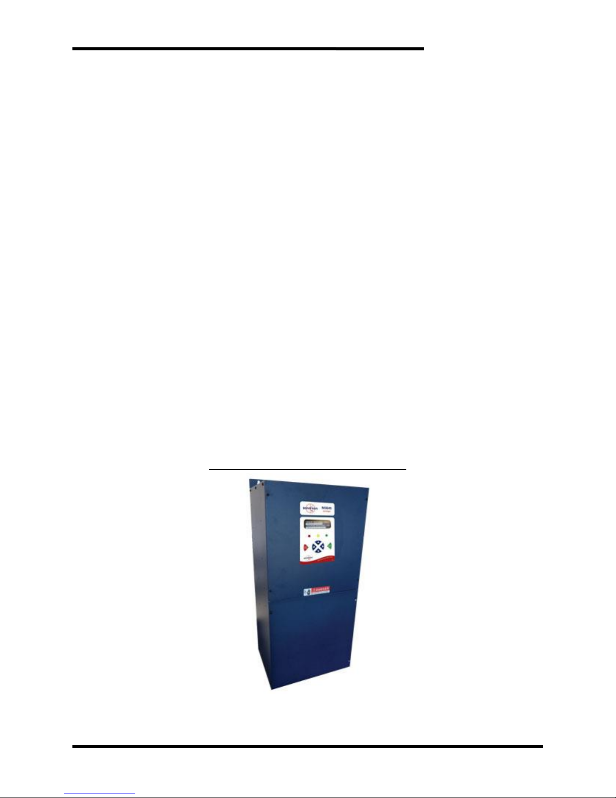
Figure 1-1: Typical M3645 Line Regen
Page 8
M3645
8
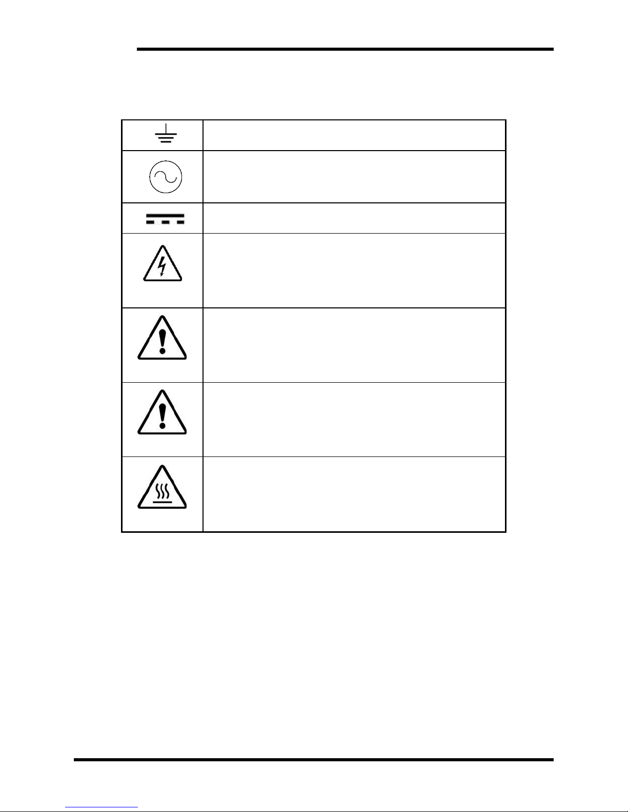
1.4. SYMBOL CONVENTIONS USED IN THIS MANUAL AND ON
EQUIPMENT
Earth Ground or Protective Earth
AC Voltage
DC Voltage
DANGER!
DANGER: Electrical hazard - Identifies a statement that indicates
a shock or electrocution hazard that must be avoided.
DANGER!
DANGER: Identifies information about practices or circumstances
that can lead to personal injury or death, property damage, or
economic loss.
CAUTION!
CAUTION: Identifies information about practices or
circumstances that can lead to property damage, or economic
loss. Attentions help you identify a potential hazard, avoid a
hazard, and recognize the consequences.
CAUTION!
CAUTION: Heat or burn hazard - Identifies a statement regarding
heat production or a burn hazard that should be avoided.
Page 9

User’s Manual
9
2. PRODUCT DESCRIPTION
Regenerated voltage occurs when the speed of the motor exceeds the set speed on the
drive. This can be due to braking or an overhauling load. In applications with extended
braking times, high horsepower, or where frequent regeneration occurs, the M3645 line
regen is the economical solution for controlling regenerative voltage. While resistor
solutions waste regenerated energy as heat, the Bonitron M3645 line regen returns the
regenerated energy back to the input AC line.
The M3645 line regen synchronizes to the frequency of the incoming power line, allowing
it to automatically adapt to 50Hz or 60Hz input. As the DC bus rises above the AC line
peak, the M3645 redirects current from the DC bus into the AC line to limit the rise in bus
voltage and prevent overvoltage faults. The M3645 is current limiting and will
automatically fold back or shut down in the event that unsafe conditions are detected.
With the optional digital display, the current status of the M3645 is shown and fault records
are stored along with a lifetime count of regenerative energy.
Up to two line regen units can be run in parallel for high-power applications.
2.1. RELATED PRODUCTS
LINE REGEN
M3545 Single Phase or Three Phase Line Regen (<15A)
REGENERATIVE POWER SUPPLY
M3645P Regenerative DC Bus Power Supply (<375A)
EXTERNAL PANEL MOUNTED DIGITAL DISPLAY
KIT 3645DD External Display Kit (compatible only with “L” M3645 regen)
COMMON BUS DIODES
M3345CBM Sharing Diode
BRAKING RESISTORS
M3575R Standard Duty Braking Resistors (<30A)
M3775R Various Duty Load Banks (<1600A)
BRAKING TRANSISTORS
M3452 Heavy Duty Braking Transistor (<1600A)
M3575T Standard Duty Braking Transistor (<600A)
M3675T Low HP Braking Transistor (<10A)
Page 10
M3645
10
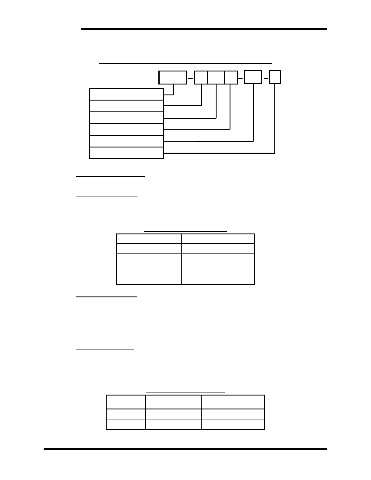
2.2. PART NUMBER BREAKDOWN
Figure 2-1: Example of M3645 Part Number Breakdown
Base Model Number
The base model number for all line regen units is M3645.
VOLTAGE RATING
A code letter represents the 3-phase AC line input voltage to the regen module. The
voltage rating must be selected for the system voltage that will be applied. See Table
2-1 for available voltage ratings.
Table 2-1: Voltage Ratings
RATING CODE
VOLTAGE
L
230 - 240VAC
E
380 - 415VAC
H
460 - 480VAC
C
575 - 600VAC
CURRENT RATING
A 3-digit number represents the maximum continuous DC Current (Amps) the regen
module can regenerate.
The M10, M11, M12 frame sizes are capable of handling a 50% overload above this
current rating for 60 seconds. The M15 frame size is capable of a 25% overload above
this current rating for 60 seconds.
300A IDENTIFIER
This single letter code is omitted except for 300A models.
Both a line reactor module and a line regen module are required for 300A models. A
single letter code is used for 300A model line regens to designate the line reactor and
the line regen.
Table 2-2: 300A Identifier
CODE
MODEL
DESCRIPTION
R
M3645-x300R
Line Reactor Module
T
M3645-x300T-M15
Line Regen Module
T
300A IDENTIFIER
CURRENT RATING
OPTIONS
VOLTAGE RATING
BASE MODEL NUMBER
CHASSIS STYLE
M3645
H
300
M15
D
Page 11
User’s Manual
11
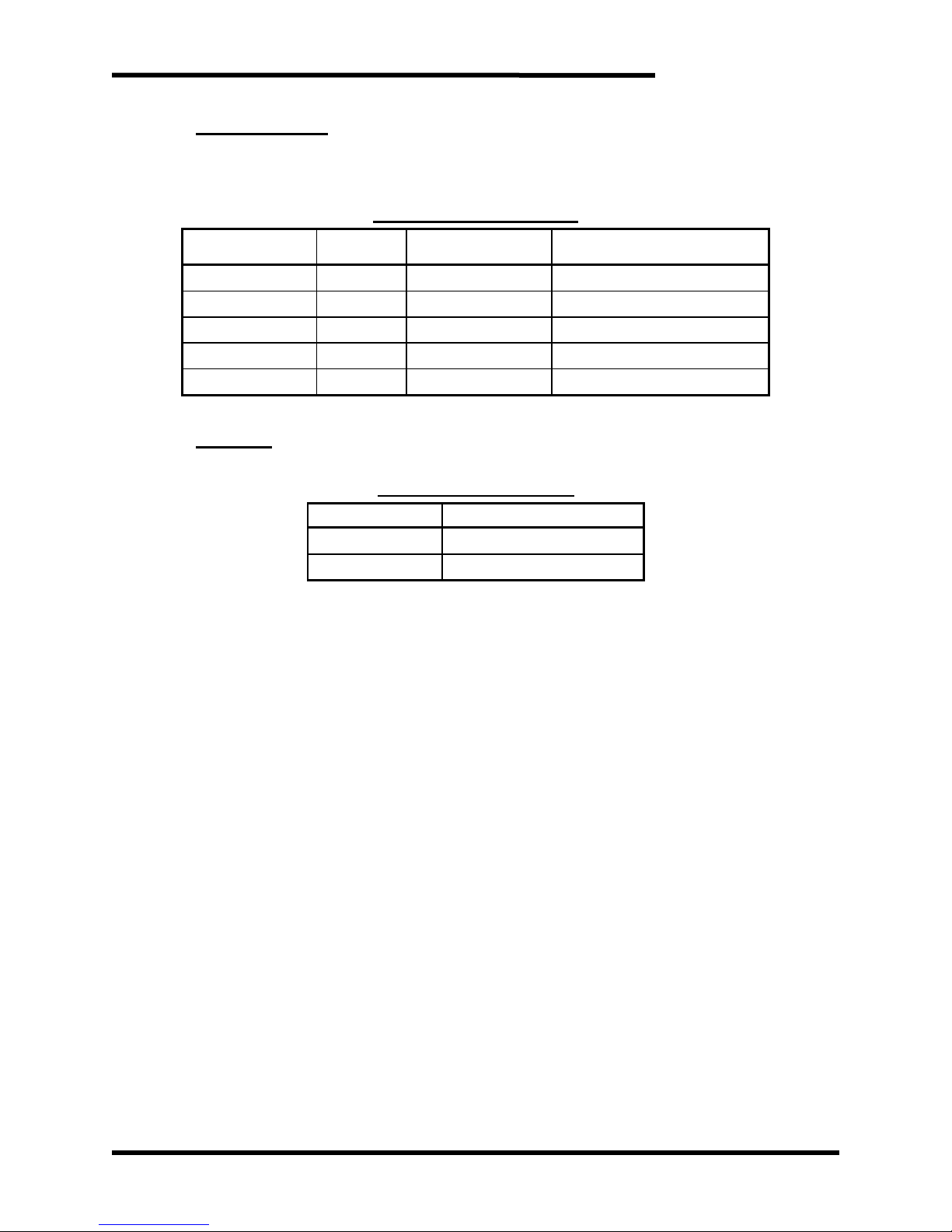
CHASSIS STYLE
The chassis style is determined by the current rating, and is represented by an
alphanumeric code as defined in Table 2-2. See Section 6.5 for chassis mounting and
dimensional outlines.
Table 2-3: Chassis Styles
CHASSIS CODE
CURRENT
DESCRIPTION
SIZE (H X W X D)
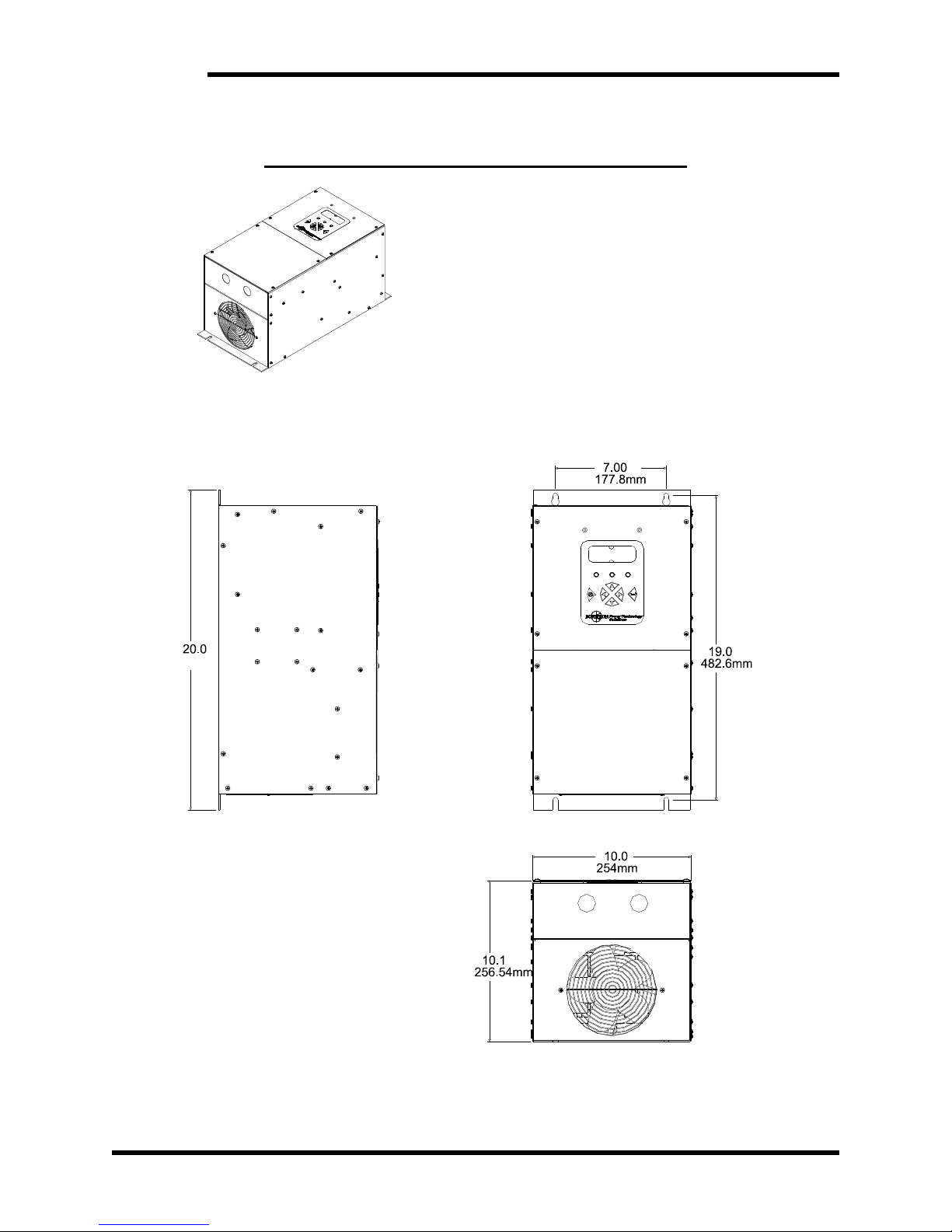
M10
30A
Open Chassis
20.0” x 10.0” x 10.1”
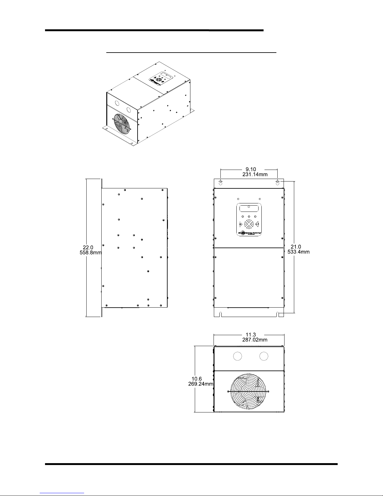
M11
50A
Open Chassis
22.0” x 11.3” x 10.6”
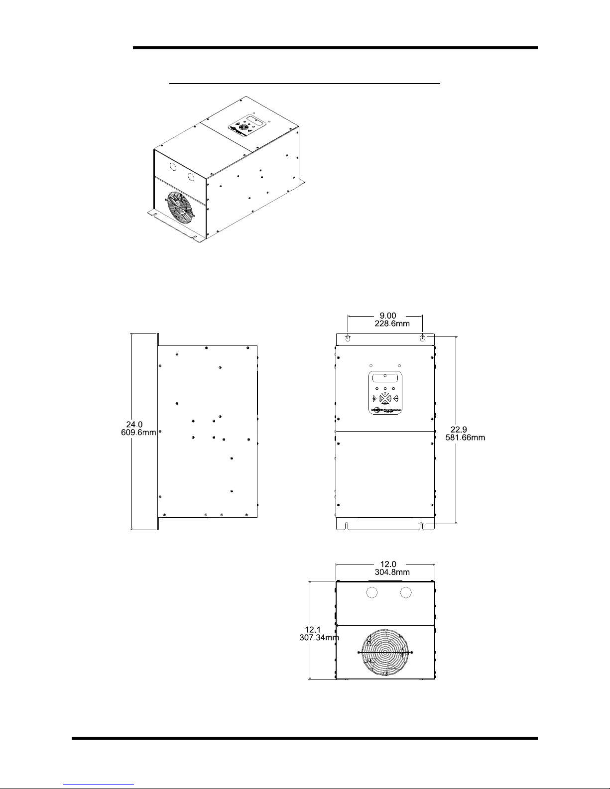
M12
100A
Open Chassis
24.0” x 12.0” x 12.1”
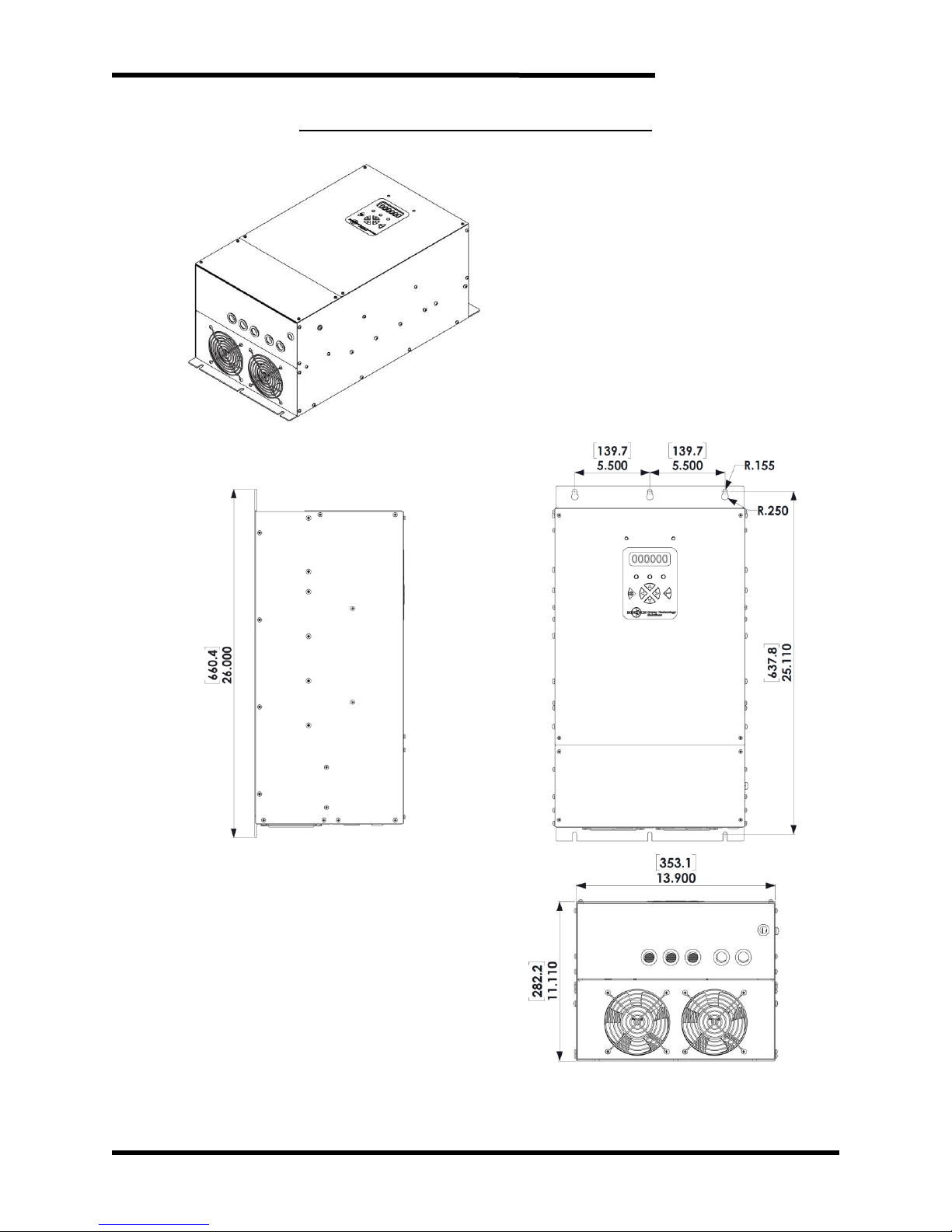
M15
300A
Open Chassis
26.0” x 13.9” x 11.1”
M15 Reactor
300A
Open Chassis
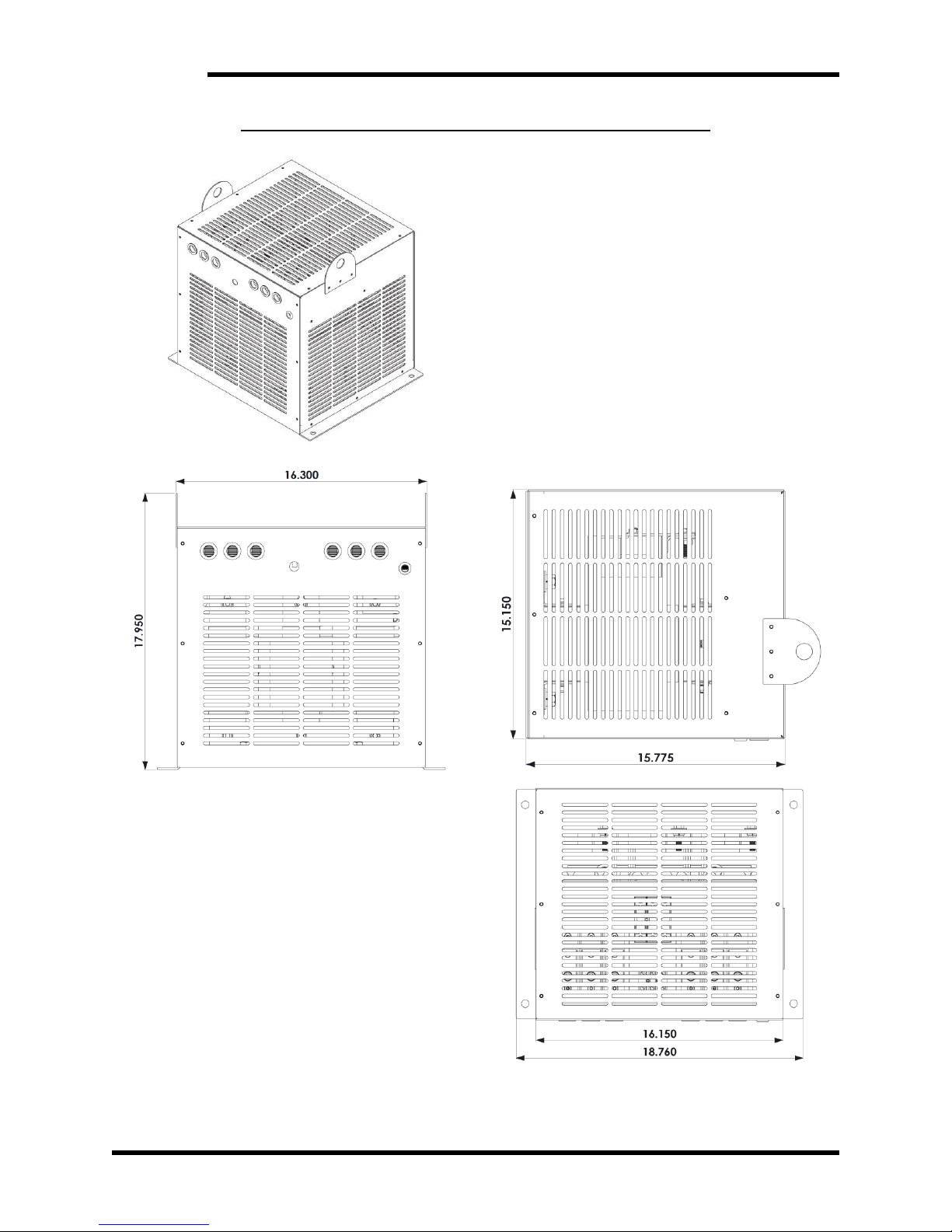
17.9” x 18.8” x 15.2”
See Section 6.5 for chassis mounting and dimensional outlines.
OPTIONS
Two display options are available.
Table 2-4: Option Codes
OPTION CODE
DESCRIPTION
D
Digital Diagnostic Display
L
Basic LED Indicators
NOTE: The KIT 3645DD external display is only compatible with “L” versions of the
M3645 line regen. Only a single display can be used for each line regen. The line
regen is unable to power more than a single display.
Page 12
M3645
12
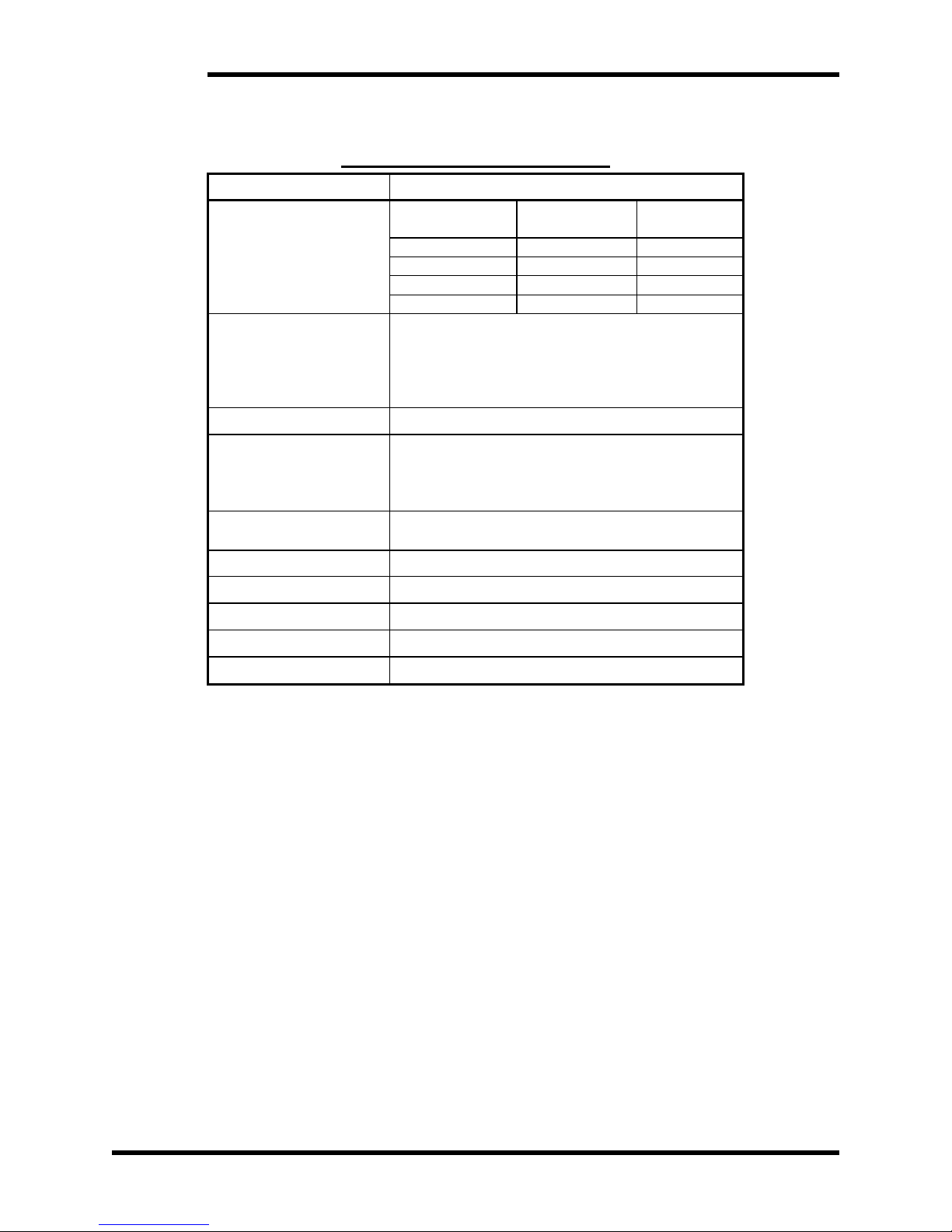
2.3. GENERAL SPECIFICATIONS CHART
Table 2-5: General Specifications
PARAMETER
SPECIFICATION
AC Line Voltage
Voltage Rating
50 or 60 Hz
Voltage Min
Voltage Max
L
207 VAC
253 VAC
E
342 VAC
418 VAC
H
414 VAC
506 VAC
C
518 VAC
600 VAC
DC Input Current
30-300A, continuous
150% of rating, 60 second overload for M10,
M11, M12 chasses
125% of rating, 60 second overload for M15
chassis
Control Voltage
Internal
Indicators
Power
Regen
Fault
Optional 4 line character display
Inputs
Enable 24VDC - 5mA
Fault Recall 24VDC – 5mA
Outputs
Ready 200VDC - 100 mA
Operating Temp
0 to +40OC
Storage Temp
-20O to +65OC
Humidity
Below 90%, non-condensing
Atmosphere
Free of corrosive gas or conductive dust
Page 13
User’s Manual
13
2.4. GENERAL PRECAUTIONS AND SAFETY WARNINGS
DANGER!
HIGH VOLTAGES MAY BE PRESENT!
NEVER ATTEMPT TO OPERATE THIS PRODUCT WITH THE ACCESS
DOORS OR COVERS OPENED!
NEVER ATTEMPT TO SERVICE THIS PRODUCT WITHOUT FIRST
DISCONNECTING POWER TO AND FROM THE UNIT!
FAILURE TO HEED THESE WARNINGS MAY RESULT IN
SERIOUS BODILY INJURY OR DEATH!
CAUTION!
THIS PRODUCT WILL GENERATE HIGH AMBIENT TEMPERATURES
DURING OPERATION.
THIS PRODUCT SHOULD BE INSTALLED ON A NON-FLAMMABLE
SURFACE WITH CLEARANCES OF AT LEAST TWO INCHES IN ALL
DIRECTIONS.
ALWAYS ALLOW AMPLE TIME FOR THE UNIT TO COOL BEFORE
ATTEMPTING SERVICE ON THIS PRODUCT.
BEFORE ATTEMPTING INSTALLATION OR REMOVAL OF THIS
PRODUCT, BE SURE TO REVIEW ALL DRIVE AND/OR RESISTIVE
LOAD DOCUMENTATION FOR PERTINENT SAFETY PRECAUTIONS.
INSTALLATION AND/OR REMOVAL OF THIS PRODUCT SHOULD
ONLY BE ACCOMPLISHED BY A QUALIFIED ELECTRICIAN IN
ACCORDANCE WITH NATIONAL ELECTRICAL CODE OR
EQUIVALENT REGULATIONS.
ANY QUESTIONS AS TO APPLICATION, INSTALLATION OR SERVICE
SAFETY SHOULD BE DIRECTED TO THE EQUIPMENT SUPPLIER.
Page 14

M3645
14
This page intentionally left blank
Page 15

User’s Manual
15
3. INSTALLATION INSTRUCTIONS
CAUTION!
Installation and/or removal of this product should only be performed by a
qualified electrician in accordance with National Electrical Code or local
codes and regulations.
Proper installation of the M3645 regen modules should be accomplished following the steps
outlined below. Be sure to refer to the AC drive instruction manual as these steps are
performed. Please direct all installation inquiries that may arise during the installation and
start-up of this product to the equipment supplier or system integrator.
3.1. ENVIRONMENT
The module should be installed in an area protected from moisture and falling debris.
Buildup of dust or debris may cause poor performance and possibly a failure.
Operating in a wet environment can pose a shock hazard. The recommended
temperature range for operating this module is 0 to +40C.
Device shall be installed in a Pollution Degree 2 environment.
3.2. UNPACKING
Upon receipt of this product, please verify that the product received matches the
product that was ordered and that there is no obvious physical damage to the unit. If
the wrong product was received or the product is damaged in any way, please contact
the supplier from which the product was purchased.
3.3. MOUNTING
3.3.1. M3645 LINE REGEN MOUNTING
The installation site for the M3645 line regen should be chosen with several
considerations in mind:
When mounting regen units in an enclosure, power dissipation should be taken
into account. Refer to Section 6.3 Watt Loss for details.
The unit requires a minimum clearance of two (2) inches in all directions around it
when not mounted near a heat source. Heat sources may increase necessary
clearances.
Unit should not be exposed to falling debris or condensation.
Once the installation site has been selected as outlined above, the unit should be
mounted in place.
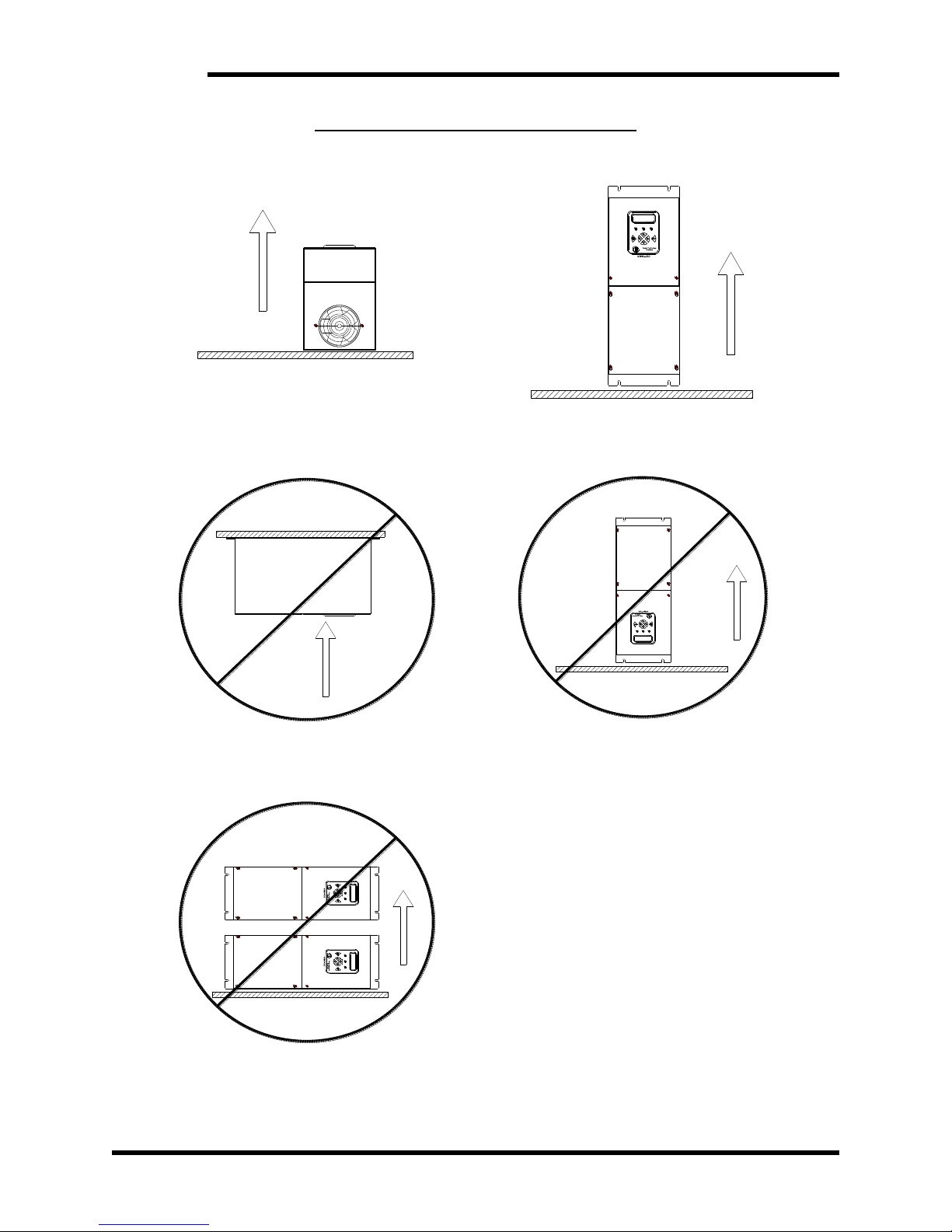
The M3645 must be properly oriented for proper heat flow through the unit. The M3645
must be mounted with the rear surface of the unit to the mounting surface. The unit
may be mounted vertically (Figure 3-1D), or with its backplane down and parallel to
the ground (Figure 3-1A).
Do Not mount the unit on the underside of a mounting surface as shown in Figure 31B.
Do Not mount the unit in a horizontal position with its side parallel to the mounting
surface or floor as shown in Figure 3-1C.
Do Not mount the unit in an upside-down position, as shown in Figure 3-1E.
Refer to Table 2-3: Chassis Styles to determine the chassis for the unit. Mounting
dimensions and provisions vary by unit chassis. See Figure 3-1 for mounting
orientation information and Section 6.6 for dimensional drawings.
Page 16
M3645
16
Figure 3-1: M3645 Mounting Orientation
Figure 3-1A
Figure 3-1D
HORIZONTAL SURFACE
UP
UP
BONITRON
Figure 3-1B
Figure 3-1E
UP
HANGING UNDERSIDE
UP
BONITRON
Figure 3-1C
UP
PARALLEL TO FLOOR
BONITRON BONITRON
Page 17
User’s Manual
17
3.3.2. M3645-X300R LINE REACTOR MOUNTING
The installation of the M3645-x300R line reactor should be chosen with several
considerations in mind:
The M3645-x300R line reactor is only required when using the 300A rated
M3645 in the M15 chassis.
When mounting the line reactor in an enclosure, power dissipation should be
taken into account. Refer to Section 6.3 Watt Loss for details.
The unit requires a minimum clearance of two inches (2”) in all directions around
it when not mounted near a heat source. Heat sources may increase necessary
clearances.
Unit should not be exposed to falling debris or condensation.
The unit can be mounted in any orientation.
Once the installation site has been selected as outlined above, the unit should be
mounted in place. See Section 6.6 for dimensional drawings.
3.3.3. KIT 3645DD, EXTERNAL DISPLAY MOUNTING
The KIT 3645DD external display is comprised of the display board assembly (ASM
3645D3) and a 12 foot long cable (CBL 3660DD4-DI12). The installation should be
chosen with several considerations in mind:
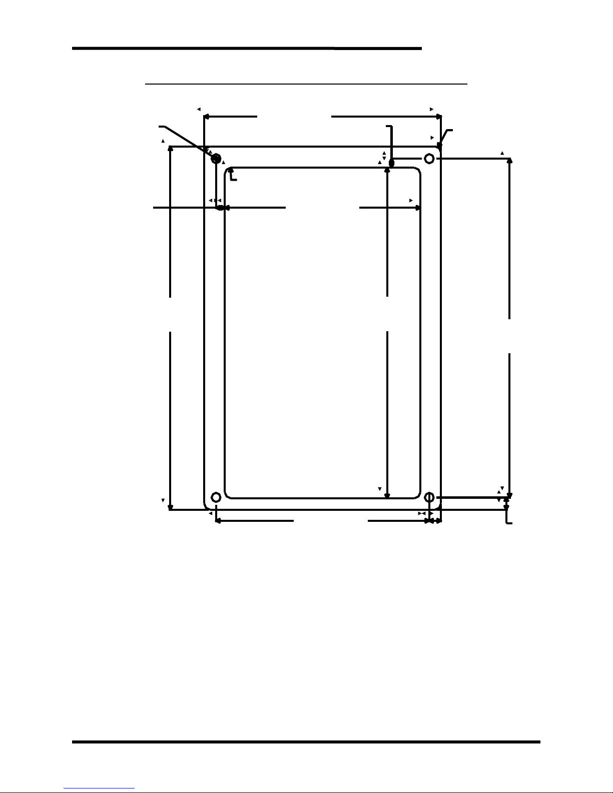
The external display requires a cutout from the front panel. See Figure 6-6 for the
dimensional requirements for the cutout.
The display will attach to the front of the panel. The display is secured to the
panel with a screw in each corner.
The unit requires a minimum clearance of one (1) inch in all directions around it.
The unit should not be exposed to falling debris or condensation.
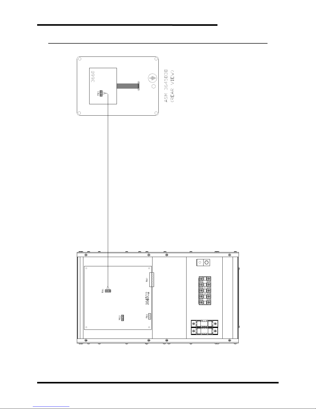
The 12 foot cable provided with the display must be attached to TB5 on the
control board of the M3645 and to TB3 on the ASM 3645D3 on the rear of the
display. See Figure 3-12.
Once the installation site has been selected as outlined above, the unit should be
mounted in place. See Section 6.6 for dimensional drawings.
NOTE: The KIT 3645DD is only compatible with “L” versions of the M3645 line regen.
Only a single display can be used for each line regen. The line regen is unable to
power more than a single display.
3.4. WIRING AND CUSTOMER CONNECTIONS
Be sure to review all pertinent AC drive and system documentation as well as the
information listed below before proceeding. Connection points and terminal numbers
of the AC drive will be found in the documentation provided with those units. See
Tables 3-1 thru 3-6 and Figures 3-2 thru 3-8 for connection details.
3.4.1. POWER WIRING
CAUTION!
Only qualified electricians should perform and maintain the interconnection
wiring of this product. All wiring should be in accordance with local codes.
DANGER!
Do NOT daisy chain the AC, DC, or ground connections between multiple
regen units. Each regen should have separate power and ground
connections.
Page 18
M3645
18
Where possible, minimize the wire length between the regen and the
drive. The wire length should not exceed 10 feet.
Avoid routing and bundling the regen AC/DC wire with the drive AC PWM
motor output wiring.
3.4.1.1. 3-PHASE AC INPUT
Do not install chokes or reactors between the regen and the power source
besides the M3645-x300R. If the AC drive requires a line reactor, the
regen should be connected to the utility grid side.
If an isolation transformer is to be used, the regen AC input MUST be
connected to the same point as the drive AC input. The transformer
should meet the ratings shown in Table 3-1.
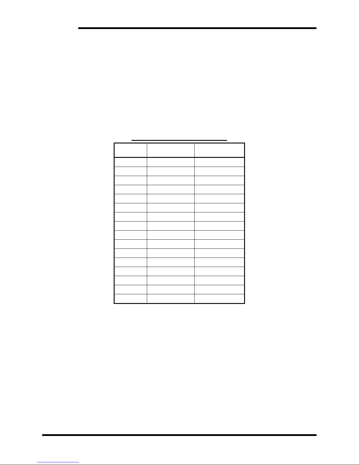
Table 3-1: Transformer Ratings
Model
Minimum kVA
Maximum
Impedance
L30
13.5 kVA
5.0%
E30
23 kVA
2.9%
H30
26.5 kVA
2.5%
C30
33 kVA
2.0%
L50
22 kVA
6.0%
E50
38 kVA
3.4%
H50
44 kVA
3.0%
C50
55 kVA
2.4%
L100
44 kVA
6.3%
E100
75.5 kVA
3.6%
H100
87.5 kVA
3.1%
C100
109.5 kVA
2.5%
L300
131 kVA
4.4%
E300
226.5 kVA
2.5%
H300
262 kVA
2.2%
C300
327.5 kVA
1.7%
Do not connect to a generator. For further details, contact Bonitron.
The regen units are not phase sensitive.
The AC line connections should have short-circuit current protection.
Recommended fuses are listed in Section 6.5.
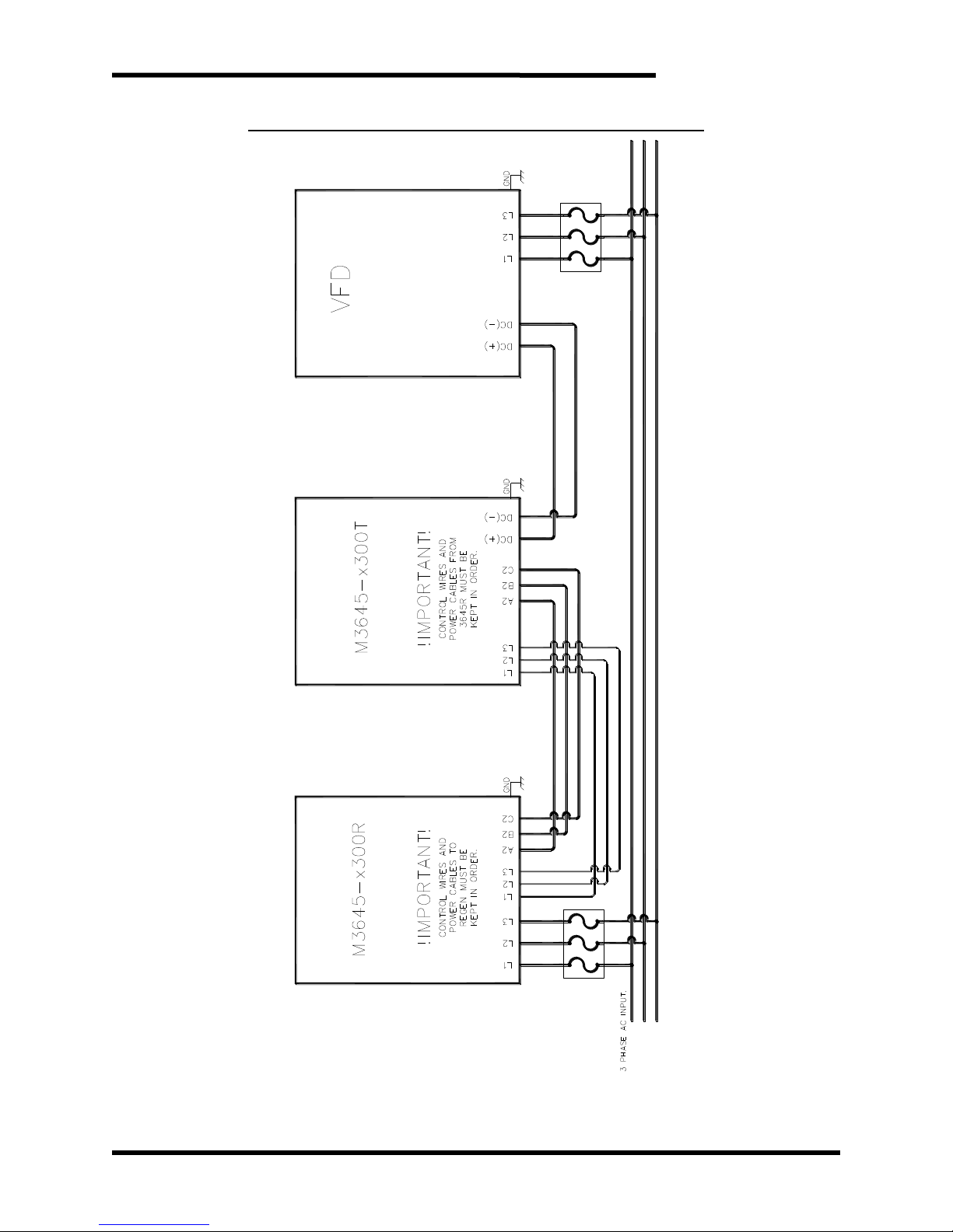
3.4.1.2. INTER-MODULE WIRING FOR 300A ONLY
For M3645 rated for 300A an individual line reactor must be used in
front of each M3645-x300T transistor module. See Figure 3-10 for
wiring diagram.
The user must wire both the control AC wiring from the M3645-x300R
line reactor to the M3645-x300T transistor module.
The control wiring must be connected to the utility side of the M3645x300R and is phase sensitive.
Page 19
User’s Manual
19
DANGER!
The AC control wiring to the M3645-x300T is phase sensitive. If the AC
control wiring is not in phase with power wiring catastrophic damage to
equipment will result.
3.4.1.3. DC BUS INPUT
The DC bus input may be connected to the DC bus of an AC drive, the
DC output of a diode sharing unit, or to a common DC bus. If a reactor
or choke are being used in the bus, make sure the actual connection is in
parallel with filter capacitors of the drive/inverter.
DANGER!
Never attach the DC bus input of the M3645 to braking terminals on the AC
drive, commonly marked “BR”. These terminals are intended for use with an
external resistor, and are not directly connected to the bus filter capacitors of
the drive. Damage may occur if these terminals are used.
Please refer to your AC drive manual or AC drive technical support department
for assistance with this connection.
3.4.1.4. GROUNDING
Using the ground stud provided, ground the chassis in accordance with
local codes. Typically, the wire gauge will be the same as is used to
ground the attached drive.
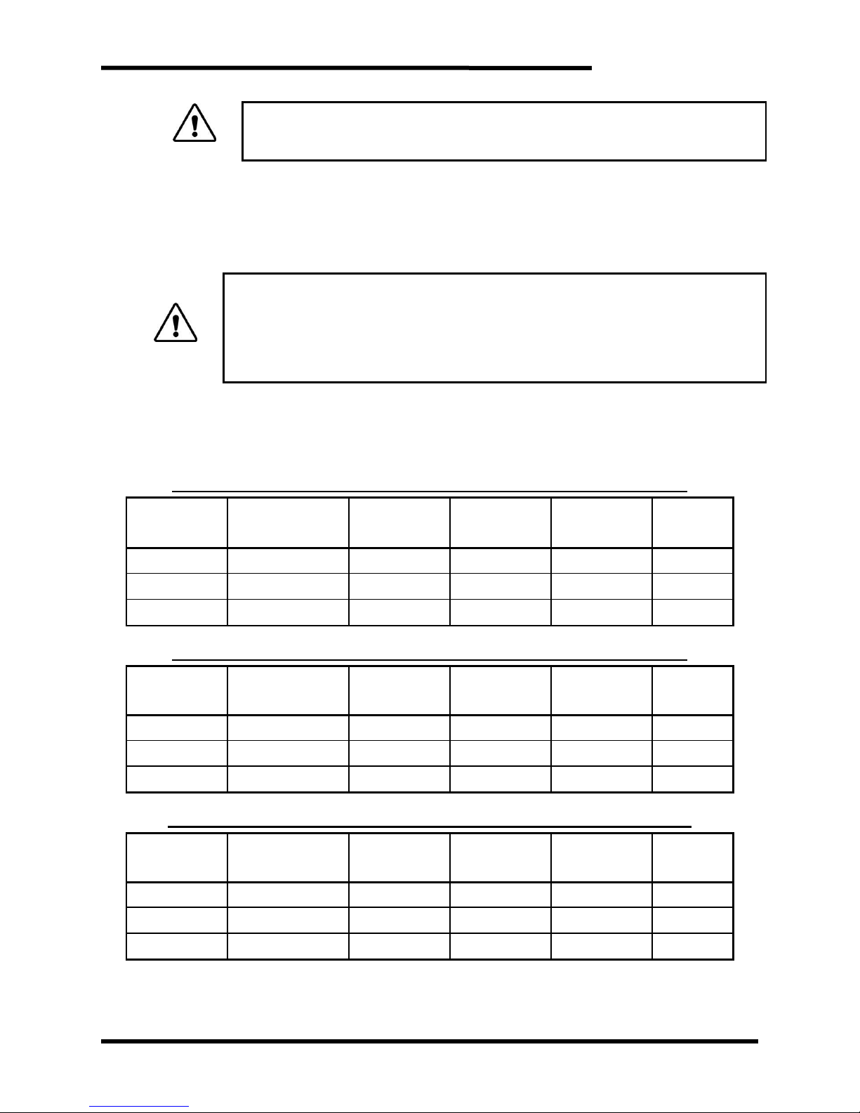
Table 3-2: Power Terminal Specifications - 30 Amp Unit – M10 Chassis
TERMINALS
FUNCTION
ELECTRICAL
RATINGS
WIRE SIZE
MINIMUM
WIRE SIZE
MAXIMUM
TORQUE
DC+, DC-
DC bus inputs
30A
8 AWG
2 AWG
32 lb-in
GND
Ground
10 AWG
1/0
50 lb-in
Table 3-3: Power Terminal Specifications - 50 Amp Unit – M11 Chassis
TERMINALS
FUNCTION
ELECTRICAL
RATINGS
WIRE SIZE
MINIMUM
WIRE SIZE
MAXIMUM
TORQUE
DC+, DC-
DC bus inputs
50A
4 AWG
2/0
120 lb-in
GND
Ground
8 AWG
1/0
50 lb-in
Table 3-4: Power Terminal Specifications - 100 Amp Unit – M12 Chassis
TERMINALS
FUNCTION
ELECTRICAL
RATINGS
WIRE SIZE
MINIMUM
WIRE SIZE
MAXIMUM
TORQUE
DC+, DC-
DC bus inputs
100A
1 AWG
2/0
120 lb-in
GND
Ground
6 AWG
1/0
50 lb-in
Note: All power wire should be selected to match or exceed the voltage rating of the unit.
Field wiring for terminals will be copper 75°C wire only.
Page 20
M3645
20
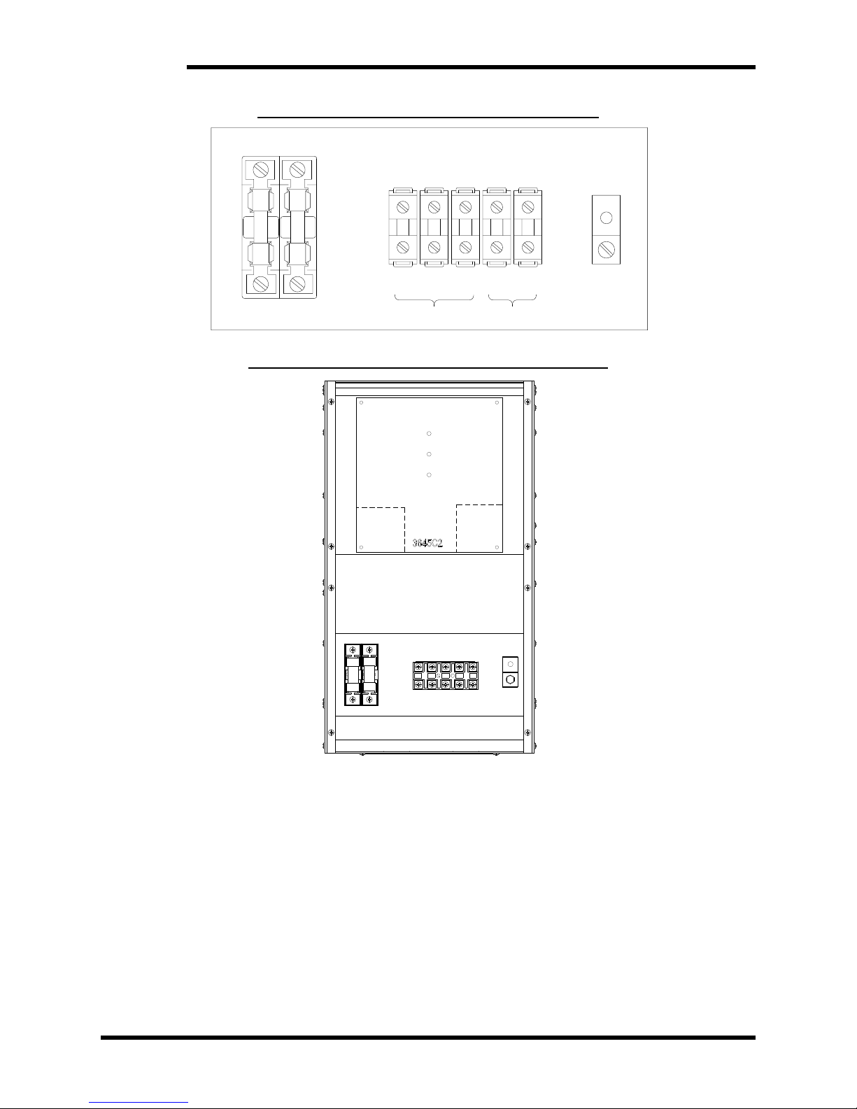
Figure 3-2: 30A, 50A, 100A Power Connections
NO CONNECTION
L1 L2 L3 + -
GND
3ØAC INPUT DC BUS
Figure 3-3: 30A, 50A, 100A Connection Locations
USER
I/0
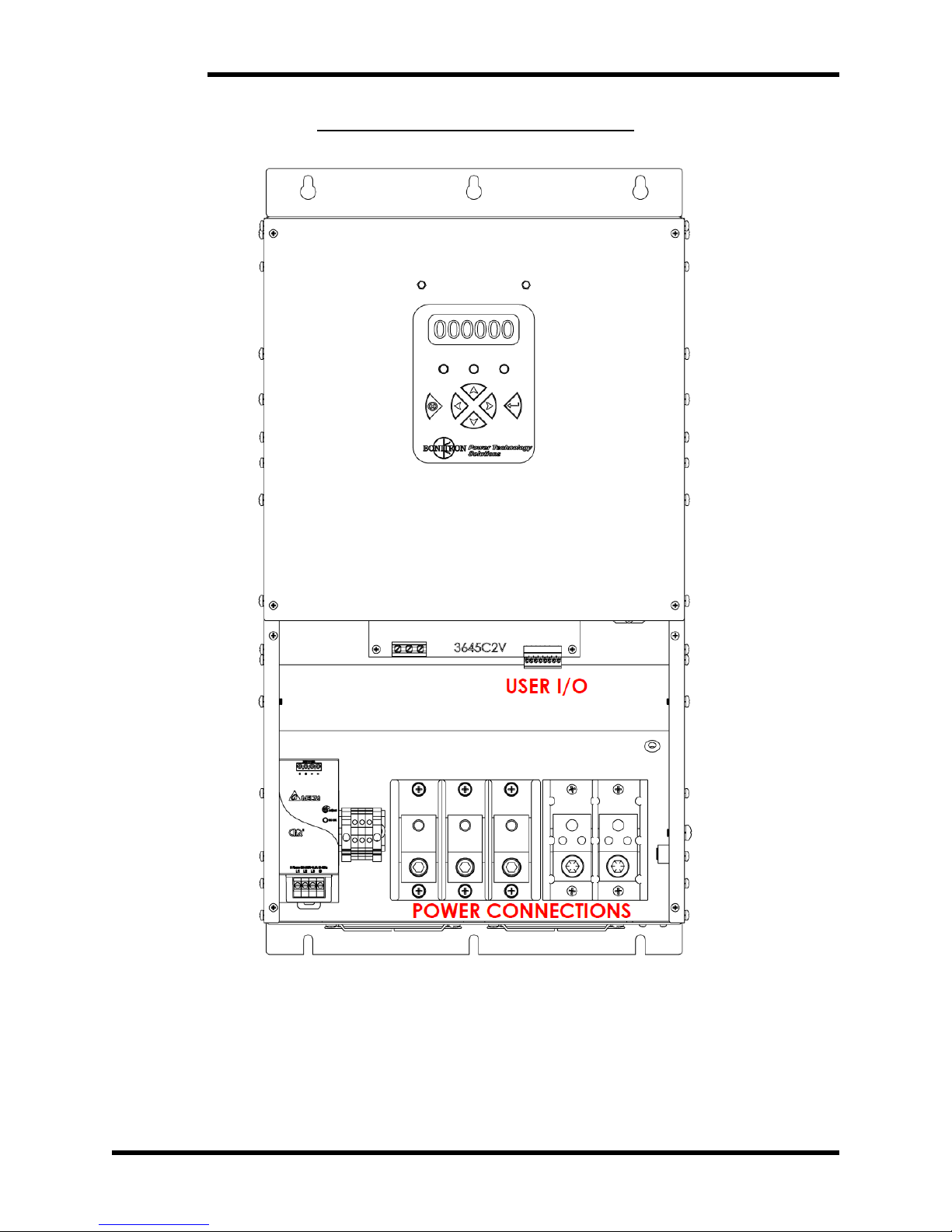
POWER CONNECTIONS
AC
SENSE
Page 21
User’s Manual
21
DANGER!
The AC control wiring to the M3645-x300T is phase sensitive. If the AC
control wiring is not in phase with power wiring catastrophic damage to
equipment will result.
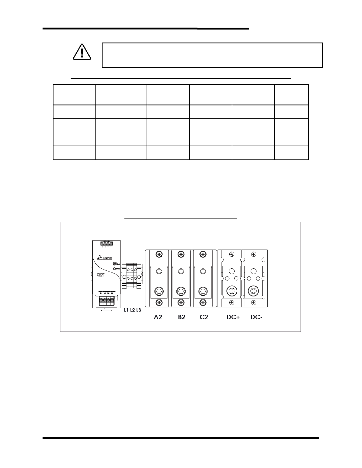
Table 3-5: Power Terminal Specifications - 300 Amp Unit – M15 Chassis
TERMINALS
FUNCTION
ELECTRICAL
RATINGS
WIRE SIZE
MINIMUM
WIRE SIZE
MAXIMUM
TORQUE
L1, L2, L3
AC control power
18 AWG
10 AWG
4.4 lb-in
A2, B2, C2
AC line outputs
300A
350 kcmil
350 kcmil
275 lb-in
DC+, DC-
DC bus inputs
300A
350 kcmil
350 kcmil
275 lb-in
GND
Ground
3 AWG
1/0
50 lb-in
Notes:
L1, L2, L3 AC control power and A2, B2, C2 AC line output are phase sensitive, switching the order
of phases to any of the inputs may result in damage to the regen. L1 is the same phase as A1. L2
is the same phase as A2. L3 is the same phase as A3.
All power wire should be selected to match or exceed the voltage rating of the unit.
Field wiring for terminals will be copper 75°C wire only.
Figure 3-4: 300A Power Connections
Page 22
M3645
22
Figure 3-5: 300A Connection Locations
Page 23
User’s Manual
23
3.4.2. I/O WIRING
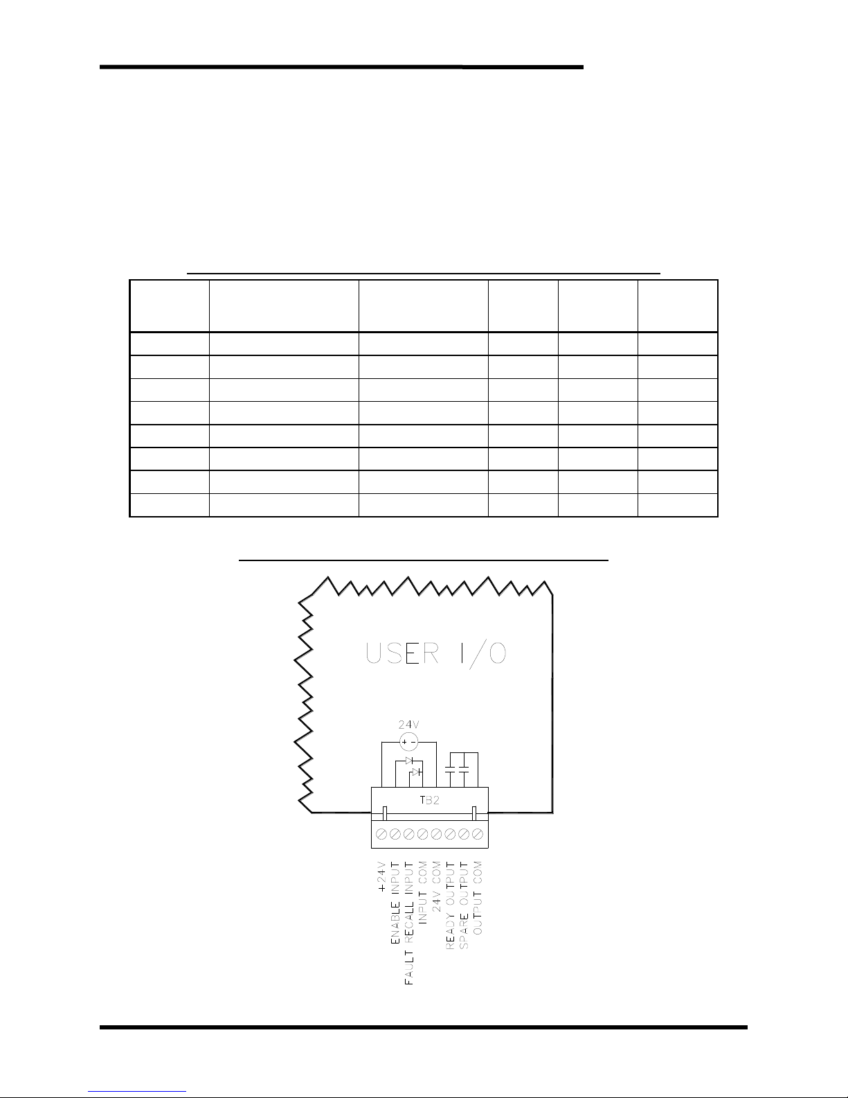
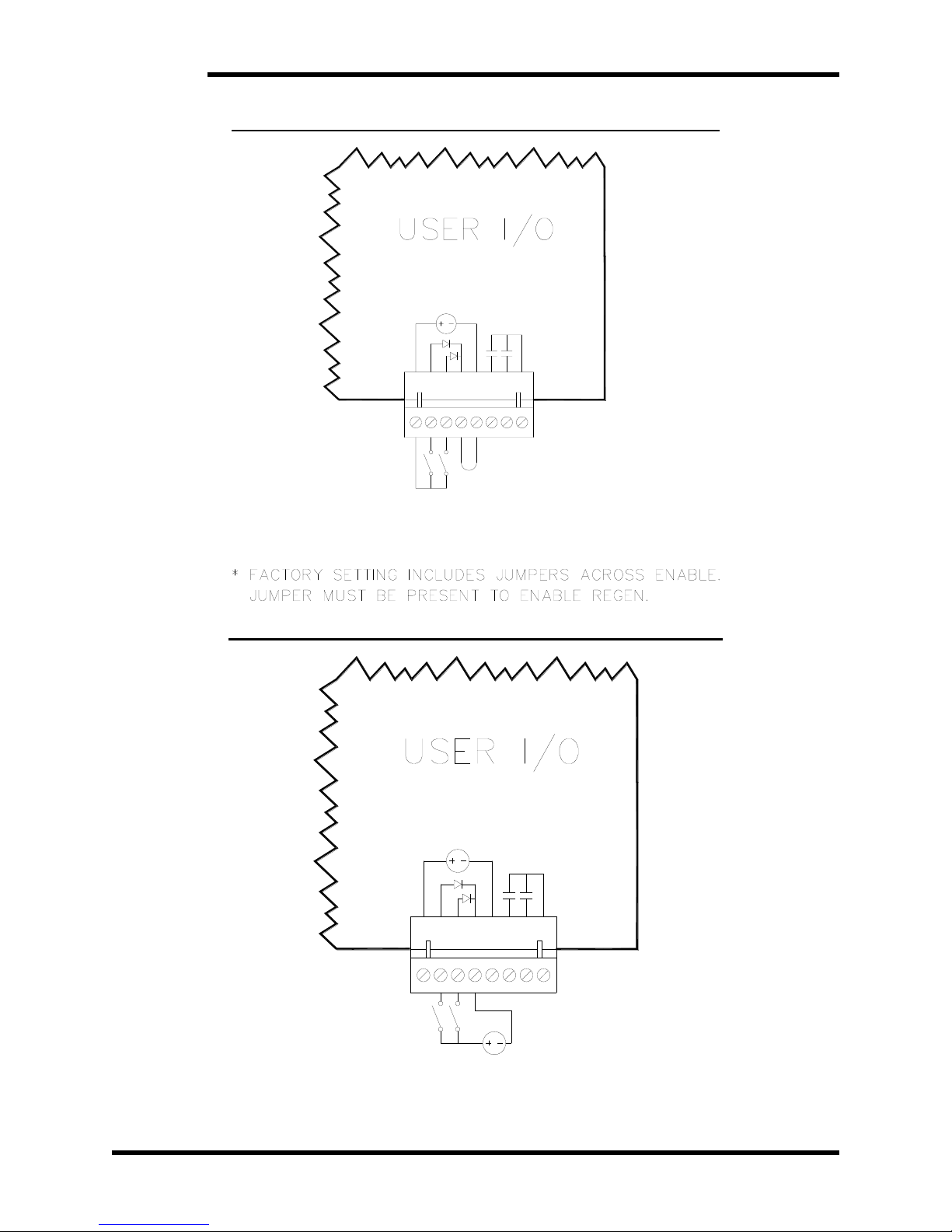
User I/O is connected via TB2 on the internal 3645C2 circuit board. To access
this terminal, the front panels of the unit must be temporarily removed. The
inputs can be driven either from an external 24VDC supply, or from the
internal 24V supply. To use the internal 24V supply, TB2-4 and TB2-5
must be shorted.
No additional I/O wiring is required for running multiple M3645 line regens in
parallel.
Table 3-6: M3645 30A, 50A, 100A User I/O Terminal Specifications
TERMINAL
FUNCTION
ELECTRICAL
SPECIFICATIONS
MIN WIRE
AWG
MAX WIRE
AWG
TORQUE
TB2-1
+24V
24VDC to TB2-5
18
16
2.2 lb-in
TB2-2
Enable Input
24VDC 5mA
18
16
2.2 lb-in
TB2-3
Fault Recall Input
24VDC 5mA
18
16
2.2 lb-in
TB2-4
Input COM
COM to TB2-2, -3
18
16
2.2 lb-in
TB2-5
24V COM
COM to TB2-1
18
16
2.2 lb-in
TB2-6
Ready Output NO
250V 150 mA
18
16
2.2 lb-in
TB2-7
Overtemp Output NO
250V 150 mA
18
16
2.2 lb-in
TB2-8
Output COM
COM to TB2-6, -7
18
16
2.2 lb-in
Note: Field wiring for terminals will be copper 75°C wire only.
Figure 3-6: M3645 30A, 50A, 100A User I/O Diagram
1 2 3 4 5 6 7 8
Page 24
M3645
24
Figure 3-7: M3645 Enable Input Using Internal Power Supply
TB2
24V
1 2 3 4 5 6 7 8
ENABLE
FAULT RECALL
Figure 3-8: M3645 Enable Input Using External Power Supply
TB2
24V
24V
1 2 3 4 5 6 7 8
ENABLE
FAULT RECALL
Page 25

User’s Manual
25
3.5 TYPICAL CONFIGURATIONS
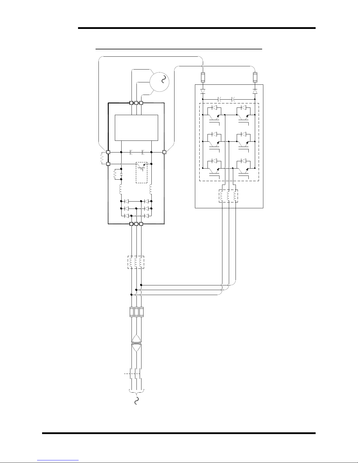
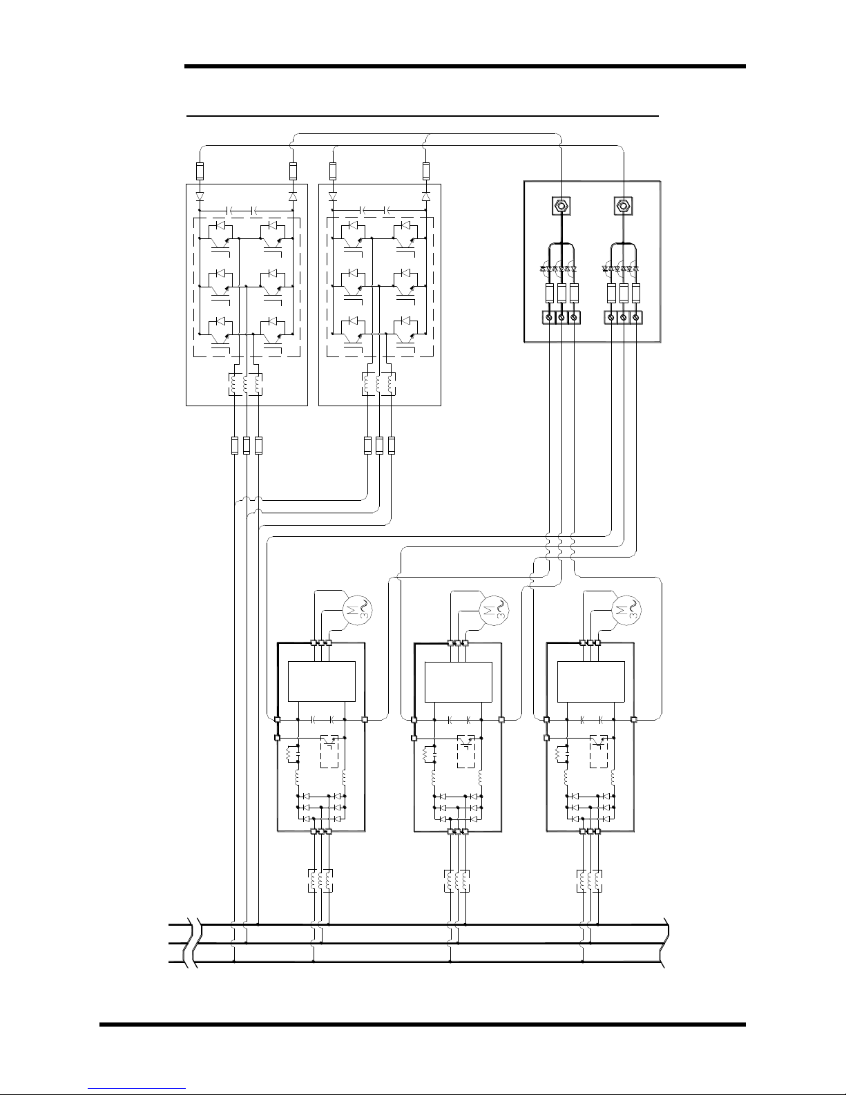
The diagrams shown in Figures 3-9, 3-10, 3-11 illustrate typical connections of the
M3645 regen units with generic VFDs. There are many other configurations that may
be applied providing a basic connection criterion is maintained such as:
The AC input should maintain a low impedance path back to the grid.
No reactors should be connected upstream of the regen unit without consulting
Bonitron for instructions.
The DC input should be connected to a fixed bus whether from a common bus
supply or from the output of a VFD. This should never be connected to a switching
source such as the braking resistor terminals on some drives.
The DC input should not be connected to an active front end drive without
instructions from Bonitron.
Page 26
M3645
26
Figure 3-9: M3645 30A, 50A, 100A Regen Power Wiring
CHOPPER
BRAKING
INTERNAL
VFD
INVERTER
EXTERNAL
RESISTOR
M
3
3
Disconnect
Isolation
Transformer
(if used)
REGEN
DC-
DC+
Line Reactor
(if used)
Page 27
User’s Manual
27
Figure 3-10: M3645 300A Regen Customer Power Wiring
Page 28
M3645
28
Figure 3-11: M3645 Multiple Drives / Regens Field Wiring Diagram
DC -
DC +
M3345CBM
DRIVE 1 DC -
DRIVE 2 DC -
DRIVE 3 DC -
DRIVE 3 DC +
DRIVE 2 DC +
DRIVE 1 DC +
NEG.
REGEN
REGEN
POS.
DRIVE 1
CHOPPER
BRAKING
INTERNAL
INVERTER
DC+
DRIVE 2
CHOPPER
BRAKING
INTERNAL
INVERTER
DC+
DRIVE 3
CHOPPER
BRAKING
INTERNAL
INVERTER
DC+
REGEN
REGEN
DC+
DC-
DC-
DC-
Page 29
User’s Manual
29
Figure 3-12: M3645 Connection with KIT 3645DD, External Panel Mounted Display
USER
I/0
POWER CONNECTIONS
Page 30

M3645
30
This page intentionally left blank
Page 31

User’s Manual
31
4. OPERATION
4.1. FUNCTIONAL DESCRIPTION
The M3645 line regen enables energy being generated by an over-hauling motor to
be efficiently returned to the power grid. Alternative solutions typically consist of
dissipating the returned energy in a resistor or simply allowing the motor to coast
uncontrolled to a stop.
The M3645 line regen synchronizes to the frequency of the attached power line,
automatically adapting to 50Hz or 60Hz. As the DC bus rises above the AC line peak,
the regen drives current from the DC bus into the AC line to limit the rise in bus voltage.
The regen is self-limiting, and will automatically fold back or shut down in the event
that unsafe conditions are detected. The internal structure of the regen prevents the
AC line from sourcing current to the DC bus.
An optional digital display shows information about the regen's present status and
history. Fault records and a lifetime count of energy regenerated are stored. On units
without digital displays, system information is presented via three color LEDs.
4.2. FEATURES
4.2.1. DIGITAL DISPLAY
The optional display is a four-line, eighty-character LCD which shows
information about the present status of the regen, as well as records of faults
and energy throughput.
4.2.2. LEDS
Red, yellow, and green LEDs indicate the status of the regen.
4.2.2.1. POWER (GREEN) INDICATOR
The green LED indicates that the unit is powered on.
4.2.2.2. REGEN ACTIVE (YELLOW) INDICATOR
The yellow LED indicates that the unit is actively regenerating power back
to the line.
4.2.2.3. NOT READY (RED) INDICATOR
The red LED indicates that the unit is not ready to run. The red LED will
be off during normal operation.
On units with a digital display, the red LED will illuminate if a fault has
occurred, or if the unit’s enable input (4.5.2) is not activated. In case of a
fault, the display will indicate the nature of the fault.
On units without a digital display, the red LED turns on solid if the enable
input (4.5.2) is not activated. If any faults are present, the red Not Ready
LED will blink out a code indicating the present fault (Table 4-1).
4.2.3. BUTTONS
Up, down, left, right, cancel, and enter buttons are present on the face of
regen units equipped with a digital display. The function of each button
depends on the active screen. See Section 4.3 for details.
Page 32

M3645
32
4.3. DIGITAL DISPLAY OPERATION
These screens display information about the M3645 on units equipped with digital
displays or those equipped with the KIT 3645DD.
4.3.1. METERING SCREEN
This screen displays the present DC bus voltage, DC regen current, regen
power, and how long the unit has been powered on since shipment.
Left: Faults screen
Right: Faults screen
Down: Energy Records screen
4.3.2. ENERGY RECORDS SCREEN
This screen displays the total energy regenerated by the unit since shipment,
along with the total energy regenerated since the user reset the energy count.
Up: Metering screen
Down: Reset Energy Records screen
4.3.3. RESET ENERGY RECORDS SCREEN
This screen allows the user to reset the record of energy regenerated by the
unit. This screen also displays the firmware version present on the unit.
Up: Energy Records screen
Enter: Confirm reset
4.3.4. FAULTS SCREEN
This screen shows the present fault state of the unit, scrolling through all
faults detected.
Left: Metering screen
Right: Metering screen
Down: Fault Records screen
4.3.5. FAULT RECORDS SCREEN
This screen shows a record of a previous fault state, including all faults and
the time since first power-on that the fault state occurred. The display stores
the 50 most recent fault states.
Left: Previous fault in the record
Right: Next fault in the record
Up: More recent fault state
Down: Older fault state
Cancel: Faults screen
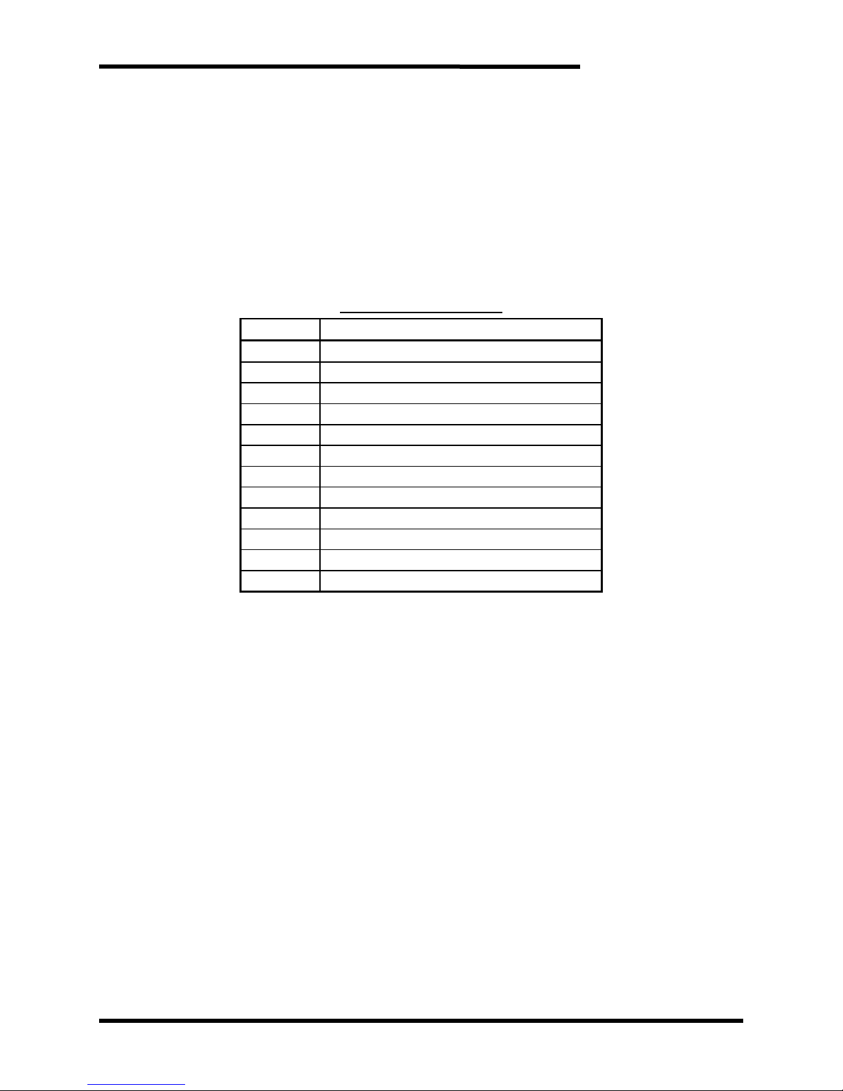
Figure 4-1: M3645 Screen Tree
FAULTS METERING
FAULT
RECORDS
ENERGY
RECORDS
ENERGY
RECORDS
RESET
Page 33
User’s Manual
33
4.4. FAULTS
The M3645 monitors a number of different fault conditions which prevent the regen
from operating. Some faults latch until they are reset by toggling the enable input.
Faults that do not latch will automatically clear when the fault condition is no longer
present. Every fault opens the Ready output contact (4.5.5).
On units with a digital display, the display stores the last 50 fault records (4.3.5). On
units without a digital display only the most recent fault state can be viewed. The unit’s
most recent fault state may be accessed by disabling the unit (4.5.2), then setting the
Fault Recall Input (4.5.3) high. The red Not Ready LED (4.2.2.3) will blink out all the
faults of the most recent fault state, in sequence.
Table 4-1: Blink Codes
FLASHES
FAULT
Solid
Unit is not Enabled
1 Fast
Feedback Undervoltage
2 Fast
Overtemperature
3 Fast
DC Overvoltage
4 Fast
Differential Overvoltage
5 Fast
Sync Loss
1 Slow
IGBT Driver
2 Slow
Phase Overcurrent
3 Slow
Phase Loss
4 Slow
DC Undervoltage
5 Slow
Regen Power-On/Precharge Not Complete
6 Slow
Frequency Detect Failure
Note:
Slow: 1 blink per second
Fast: 3 blinks per second
4.4.1. FEEDBACK UNDERVOLTAGE
This fault indicates that the M3645's DC bus feedback circuitry has failed.
This fault will latch until manually cleared by toggling the Enable Input. If this
fault does not clear, it typically indicates that damage to the M3645 has
occurred and must be repaired.
4.4.2. OVERTEMPERATURE
This fault indicates that the regen unit has exceeded its safe operating
temperature. This fault will automatically clear when the unit's temperature
has returned to a safe level.
4.4.3. DC OVERVOLTAGE
This fault indicates that the DC voltage on the bus has exceeded 1000V. This
fault latches until manually cleared.
4.4.4. DIFFERENTIAL OVERVOLTAGE
This fault indicates that the DC bus is more than 200V higher than the AC
line peak. This fault latches until manually cleared by toggling the Enable
input.
Page 34

M3645
34
4.4.5. SYNC LOSS
This fault indicates that the regen has lost synchronization with the AC line.
This fault will automatically clear if sync is reestablished, and will latch if it
cannot. If this fault recurs regularly or fails to clear, it is likely due to line
noise, a blown phase fuse, or an undersized AC source.
4.4.6. IGBT DRIVER
This fault indicates that the regen's internal transistor drive circuitry has
detected an error. This typically indicates an instantaneous overcurrent on
one of the AC legs. This fault will latch until cleared by toggling the Enable
Input. If this fault does not clear, it typically indicates that damage to the
M3645 has occurred.
4.4.7. PHASE 1-3 OVERCURRENT
These faults indicate that the current the M3645 is driving into one leg of the
AC line has exceeded a safe operating level. This is likely due to line noise.
These faults will latch until cleared by toggling the Enable input.
4.4.8. PHASE LOSS
These faults indicate that the Regen has lost voltage on one or more of the
AC line phases. These faults clear automatically when voltage is
reestablished. If these faults do not clear, it typically indicates that a line fuse
has failed.
4.4.9. DC UNDERVOLTAGE
This fault indicates that the DC voltage on the bus is less than 100V. This
fault will clear automatically when the voltage rises to an operable level. If
this fault does not clear, it typically indicates that damage to the M3645 has
occurred.
4.4.10. REGEN POWER-ON/PRECHARGE NOT COMPLETE
These faults indicate that the unit has been powered on in the last ten
seconds. This is normal. This fault will clear automatically. If this fault does
not clear, it typically indicates that damage to the M3645 has occurred.
4.4.11. FREQUENCY DETECT FAILURE
This fault indicates that the unit failed to properly detect whether the AC
source is 50 or 60 Hz. This fault latches until power-down.
Page 35

User’s Manual
35
4.5. INPUT / OUTPUT CONNECTIONS
All the inputs for the regen unit are 24VDC. The inputs are all common to TB2-4. The
inputs are bidirectional, and can be configured to be sinking or sourcing as the
installation requires. It is recommended that inputs be configured as sinking, as this
is more failsafe.
The outputs are MOSFET optocouplers, and will show a low resistance (20Ω) when
activated. When not activated, they will appear open.
4.5.1. LOCAL I/O +24V SUPPLY- TB2-1 & TB2-5
This pin supplies 24V, a maximum of 100mA, which can be used to drive the
Regen inputs. 24V+ is on TB2-1, 24VCommon is on TB2-5.
4.5.2. ENABLE INPUT - TB2-2
This input enables the M3645. Faults are reset on a rising edge of this input.
Note that the unit will not operate unless this input is on. This unit can be
jumpered high if the unit does not need remote operation. In this case, faults
must be cleared by cycling power to the Regen.
4.5.3. FAULT RECALL INPUT -TB2-3
For units with no digital display, the last fault record can be retrieved by
disabling the regen unit and activating this input.
The last fault code will blink out until the unit is re-enabled.
For units with a digital display, this input has no function.
4.5.4. INPUT COM -TB2-4
All user inputs are common to this terminal.
4.5.5. READY OUTPUT - TB2-6
This output closes to TB2-8 when the M3645 is ready to operate. This contact
will open if the system is not enabled, if the system is powered off, or on any
fault condition.
4.5.6. OVERTEMPERATURE OUTPUT - TB2-7
This output closes to TB2-8 when the unit is not indicating an overtemp fault,
and opens if the unit reaches an unsafe operating temperature. The M3645
will shut down to protect itself from damage during an overtemperature fault.
4.5.7. OUTPUT COM - TB2-8
This terminal is the common to the outputs. It is not common to TB2-4, and
allows the use of a different power supply for outputs if the installation
requires.
Page 36

M3645
36
4.6. STARTUP
This section covers basic checks and procedures that should be used when
performing a startup with a M3645 line regen.
4.6.1. PRE-POWER CHECKS
Ensure that the voltage of the AC power system is the same as the regen
unit.
Ensure that all connections are tight and that all wiring is of the proper
size and rating for operation.
Verify continuity of all input fuses prior to applying power.
Check for exposed conductors that may lead to inadvertent contact.
Check for any debris, shavings, trimmings, etc. that may cause shorts or
obstruct ventilation on unit.
4.6.2. STARTUP PROCEDURE AND CHECKS
After completing Regen pre-checks and recommended checks for connected
equipment you may apply power to the system. The Power indicator on the
front panel should illuminate. The fan should start, then stop, within ten
seconds.
Enable the M3645 by placing 24VDC on the “Enable” input. (Table 3-6 or
Table 3-7 for 300A units)
The status contact should be closed after a 2 second delay, which is an
indication that unit is ready for operation.
Observe the current on the digital display, or with a current clamp for systems
without a digital display. If more than 5 amps are flowing with the attached
drive not operating, go to the troubleshooting instructions in Section 5.3.
Once the status output closes, the regen is ready to operate, and the drive
system can be run normally.
4.6.3. COOLING FAN
The cooling fan will not run all the time. The fan runs at startup, when the unit
is regenerating, or when the unit’s internal temperature is above a certain
level. If the cooling fan never runs, there may be damage to the fan and the
unit may need repair.
Page 37
User’s Manual
37
5. MAINTENANCE AND TROUBLESHOOTING
Repairs or modifications to this equipment are to be performed by Bonitron approved
personnel only. Any repair or modification to this equipment by personnel not approved
by Bonitron will void any warranty remaining on this unit.
5.1. PERIODIC TESTING
There are no requirements for periodic testing of these units. It may be beneficial to
repeat start-up procedures and checks when performing routine maintenance.
5.2. MAINTENANCE ITEMS
Check the fan periodically for debris, and blow out with an air hose if it has become
obstructed or not running at full capacity. Power should not be applied when
blowing dust and debris out of unit.
5.3. TROUBLESHOOTING
CAUTION!
There are no user serviceable parts within the M3645 regen unit. If you
are still experiencing problems after you have reviewed this whole section,
you may contact Bonitron for additional assistance at (615) 244-2825.
5.3.1. POWER LED IS NOT ON, OR DIGITAL DISPLAY IS NOT ACTIVE:
Check AC input voltage at terminals. Voltage should be within range
specified in Table 2-1 for your unit. If the power light will not come on,
check any overcurrent devices or disconnects upstream of the regen.
If the power lamp will not come on, it is likely that the regen is damaged
and needs to be repaired.
5.3.2. READY OUTPUT WILL NOT CLOSE
The Ready output indicates that the module is enabled and in a ready
condition. When the power is applied to the module, the Ready output will
normally close after a startup delay of approximately 2 seconds. Thereafter,
the Ready output should be closed, indicating that the system is ready to
operate. If the Ready output fails to close, one of several faults may be
indicated.
Make sure the Power LED is on.
If the Fault LED is blinking, refer to Table 4-1, “Blink Codes” to determine
which fault is active, or look at the digital display.
If the Fault LED is on solid, the "Enable" input is not activated.
5.3.3. UNIT WILL NOT RESPOND TO ENABLE COMMAND
Confirm that 24V is present between TB2-2 and TB2-4 (see Figure 3-6).
If the internal 24V supply is being used, confirm that a jumper is present
between TB2-4 and TB2-5 (0).
5.3.4. DRIVE TRIPS ON DC BUS OVERVOLTAGE DURING BRAKING
If the attached drive trips, it typically indicates the regen is not operating.
There are some simple things that can determine the cause.
Make sure the regen has power and is enabled. The Ready output will
close if the unit is ready to operate. (4.5.2)
Page 38

M3645
38
If there are active faults, the unit will not operate, and the attached drive
will trip during braking.
Check DC bus voltage at fuses.
Check DC bus polarity at fuses.
Check DC bus fuses.
Ensure unit is not faulting during operation. Some faults may clear
themselves, such as phase loss, but the fault recall will show that they
have occurred. Check the fault records to see if the regen unit has other
faults that would cause the operation to stop. Once the regen stops
operating, the attached drive will fault on overvoltage during heavy
braking.
This can also mean that the regen is too small to handle the braking
requirements. If the braking energy is too high for the regen to dissipate,
the regen will go into current limit. While the regen is operating in current
limit, the DC bus may continue to rise to the point that the drive will trip.
The current being regenerated can be checked with the digital display or
with a separate meter in the DC link. Verify proper sizing of the regen
unit. If the regen is operating in current limit, the regen may be
undersized for the application.
If the regen and drive are connected to the AC line through a transformer,
the transformer may not be large enough to handle the regenerated
currents. See Section 3.4.1.1 for transformer sizing instructions.
With 300A units, confirm that the phase rotation of the AC control power
connections between the reactor and the transistor module match the
power connections.
5.3.5. FEEDBACK UNDERVOLTAGE
Reset the M3645 by toggling the enable input. (4.5.2)
If the fault returns, contact Bonitron for assistance.
5.3.6. OVERTEMPERATURE
Check the ambient temperature. If the temperature is above 40°C, the unit
may not be able to cool properly at full load. Ensure that there is adequate
clearance and airflow in the area where the regen is installed.
Check to make sure the fan is operating. The fan will operate for a few
seconds after power up. Cycle power to the regen, and listen for the fan
operation. If it does not operate, check for obstruction.
If the unit is cool, and still showing an overtemperature condition, contact
Bonitron for assistance.
If an overtemperature fault is listed in the fault log in conjunction with a
Precharge Not Complete fault, this indicates that control power to the unit has
been reset. No actual overtemperature condition has occurred.
5.3.7. DC OVERVOLTAGE ON REGEN
This fault can be reset by toggling the Enable input. (4.5.2) Check all the
conditions described in Section 5.3.3.
Confirm Enable input is active, and the unit is ready to operate.
Confirm with a voltmeter that the DC bus polarity matches the markings on
the unit.
Check the fault records to see if other faults may be keeping the unit from
operating.
Page 39

User’s Manual
39
This can also mean that the regen is too small to handle the braking
requirements. Make sure the regen is not operating in the current limit during
braking.
This fault may occur if the regen is connected to multiple drives, with blocking
diodes between each drive ant the regen. This topology is not supported.
Please contact Bonitron for possible alternative common bus solutions.
5.3.8. DIFFERENTIAL OVERVOLTAGE
Differential overvoltage can be caused by the same reasons as the DC
overvoltage. Refer to Section 5.3.7.
5.3.9. SYNC LOSS
Ensure that the overcurrent devices on the incoming AC line are intact.
Ensure that the AC source is properly sized for the application. "Soft" or high
impedance sources can have significant voltage distortion that can cause the
regen to lose sync. Most drives will not be affected by this distortion. You
can check for voltage distortion on the incoming AC line with an oscilloscope
with appropriate leads. It will be important to be watching the AC line when
the Sync Loss fault occurs, as the distortion may not be on the line all the
time, especially when it is not loaded.
If a sync loss fault is listed in the fault log in conjunction with a Precharge Not
Complete fault, this indicates that control power to the unit has been reset.
No actual sync loss condition has occurred.
5.3.10. IGBT DRIVER
This fault can be reset the M3645 by toggling the Enable input. (4.5.2)
If the fault cannot be cleared, or occurs frequently, the unit may be damaged.
Contact Bonitron for assistance.
If two M3645 units are operated in parallel, IGBT faults may indicate that the
parallel combination is undersized for the application.
5.3.11. PHASE OVERCURRENT
This fault can be cleared by toggling the enable input. (4.5.2)
If it occurs frequently, there may be a voltage imbalance on the incoming AC
line. Ensure that the incoming line voltages are within 3% of each other.
5.3.12. PHASE LOSS
This fault typically means that the incoming power overcurrent devices or
fuses are blown.
Power the regen down and check all fuses and that AC voltage is present at
the terminals of the regen.
5.3.13. DC UNDERVOLTAGE
This may indicate that overcurrent devices in the DC link may have opened.
Check the AC and DC voltages with an external voltmeter and make sure
they are within specification.
If the voltages are correct, and the fault will not clear, contact Bonitron for
assistance.
5.3.14. REGEN POWER-ON/PRECHARGE NOT COMPLETE
This fault is expected to occur every time the unit powers on. It should clear
automatically within ten seconds.
Page 40

M3645
40
If the fault does not clear automatically, power the M3645 down and check all
incoming AC and DC fuses or overcurrent devices.
Ensure that DC bus voltage is present at the terminals of the regen, at the
expected voltage. Check the polarity of the DC bus connections. If the
polarity is incorrect the regen will not be able to complete precharge.
If the fault cannot be cleared, or occurs frequently, the unit may be damaged.
Contact Bonitron for assistance.
5.3.15. FREQUENCY DETECT FAILURE
Power the M3645 down and check all incoming AC and DC fuses or
overcurrent devices.
5.3.16. TECHNICAL HELP – BEFORE YOU CONTACT US
If technical help is required, please have the following information available
when contacting Bonitron (615) 244-2825, or email to [email protected]:
Model number of unit
Serial number of unit
Name of original equipment supplier if available
Record the line to line voltage on all 3 phases
Record the DC bus voltage immediately after the AC voltage
Brief description of the application
Drive and motor HP or kW
KVA rating of power source
Source configuration Wye/Delta and grounding
Page 41
User’s Manual
41
6. ENGINEERING DATA
6.1. RATINGS CHARTS
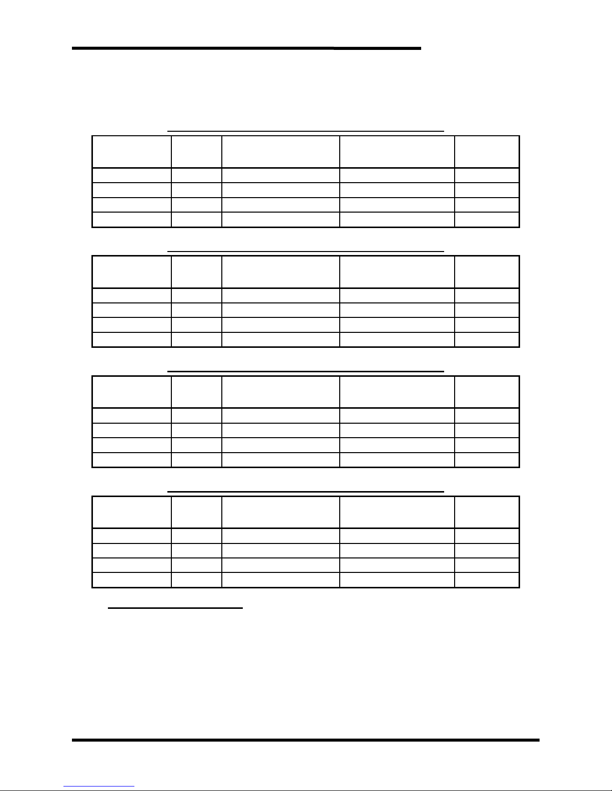
Table 6-1: Ratings and Specifications – 230 - 240VAC
MODEL
NUMBERS
CHASSIS
STYLE
DC REGEN CURRENT
POWER
MAX CONT.
WATT LOSS
CONT.
PEAK
CONT.
PEAK
M3645-L030
M10
30A
45A
14.4HP
21.6HP
180W
M3645-L050
M11
50A
75A
24.0HP
36.0HP
265W
M3645-L100
M12
100A
150A
48.0HP
72.0HP
470W
M3645-L300T
M15
300A
375A
144.0HP
180.0HP
2980W
Table 6-2: Ratings and Specifications – 380 - 415VAC
MODEL
NUMBERS
CHASSIS
STYLE
DC REGEN CURRENT
POWER
MAX CONT.
WATT LOSS
CONT.
PEAK
CONT.
PEAK
M3645-E030
M10
30A
45A
25.0HP
37.5HP
180W
M3645-E050
M11
50A
75A
41.7HP
62.6HP
265W
M3645-E100
M12
100A
150A
83.4HP
125.2HP
470W
M3645-E300T
M15
300A
375A
250.0HP
312.5HP
2980W
Table 6-3: Ratings and Specifications – 460 - 480VAC
MODEL
NUMBERS
CHASSIS
STYLE
DC REGEN CURRENT
POWER
MAX CONT.
WATT LOSS
CONT.
PEAK
CONT.
PEAK
M3645-H030
M10
30A
45A
28.8HP
43.2HP
180W
M3645-H050
M11
50A
75A
48.0HP
72.0HP
265W
M3645-H100
M12
100A
150A
96.0HP
144.0HP
470W
M3645-H300T
M15
300A
375A
288.0HP
360.0HP
2980W
Table 6-4: Ratings and Specifications – 575 - 600VAC
MODEL
NUMBERS
CHASSIS
STYLE
DC REGEN CURRENT
POWER
MAX CONT.
WATT LOSS
CONT.
PEAK.
CONT.
PEAK
M3645-C030
M10
30A
45A
36.0HP
54.0HP
180W
M3645-C050
M11
50A
75A
60.0HP
90.0HP
265W
M3645-C100
M12
100A
150A
120.0HP
180.0HP
470W
M3645-C300T
M15
300A
375A
360.0HP
450.0HP
2980W
A NOTE ON HP RATINGS
Modules are able to regenerate continuous power indefinitely. Modules can
regenerate peak power for at least 60 seconds.
Each unit’s regen current and power specifications must be derated by 2% per degree
Celsius ambient above 40°C.
Page 42
M3645
42
6.2. DERATING PARALLEL REGENS
Operating regens in parallel is useful when large regenerative energies are present
and need to be dissipated in high power applications. Currently, the 100A and 300A
frame sizes are able to be used in parallel. The combined units must have their peak
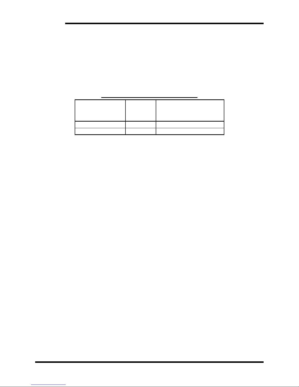
currents derated by 10% each. The derating for parallel systems is shown in Table
6-5.
Two units are the maximum number that can be safely operated in parallel. Units
with different current ratings should not be in parallel together on the same DC bus.
Table 6-5: Derating Regens in Parallel
INDIVIDUALREGEN
CURRENT RATING
NUMBER IN
PARALLEL
DC REGEN CURRENT FOR
TWO REGENS IN PARALLEL
CONT.
PEAK.
100A
2
200A
270A
300A
2
600A
675A
6.3. WATT LOSS
Tables 6-1 thru 6-4 list the maximum continuous watt loss generated by each of the
listed regen units. When installing regen units in an additional enclosure,
consideration should be given to internal temperature rise. The watt loss rating in
these tables is based upon the maximum continuous regen capability of each unit.
Applications that do not utilize the full capacity may be calculated by using the
percentage of loading for the individual unit.
The M3645 is more than 98% efficient when fully loaded.
6.4. CERTIFICATIONS AND ROHS
M3645 models with 30A, 50A, and 100A ratings are listed under UL508C, file number
E204386.
The M3645 line regen is suitable for use on a circuit capable of delivering not more
than 65 kA RMS symmetrical amperes at the rated voltage, when protected by the
recommended AC fuses. DC fusing is not required.
All M3645 models are in compliance with Directive 2011/65/EU of the European
Parliament and of the Council of 8 June 2011 on the restrictions of the use of certain
hazardous substances in electrical and electronics equipment (RoHS Directives).
Page 43
User’s Manual
43
6.5. FUSE SELECTION
Blown fuses typically indicate a semiconductor device failure or a severe transient. In
any case, blown fuses should not be replaced without first consulting Bonitron as
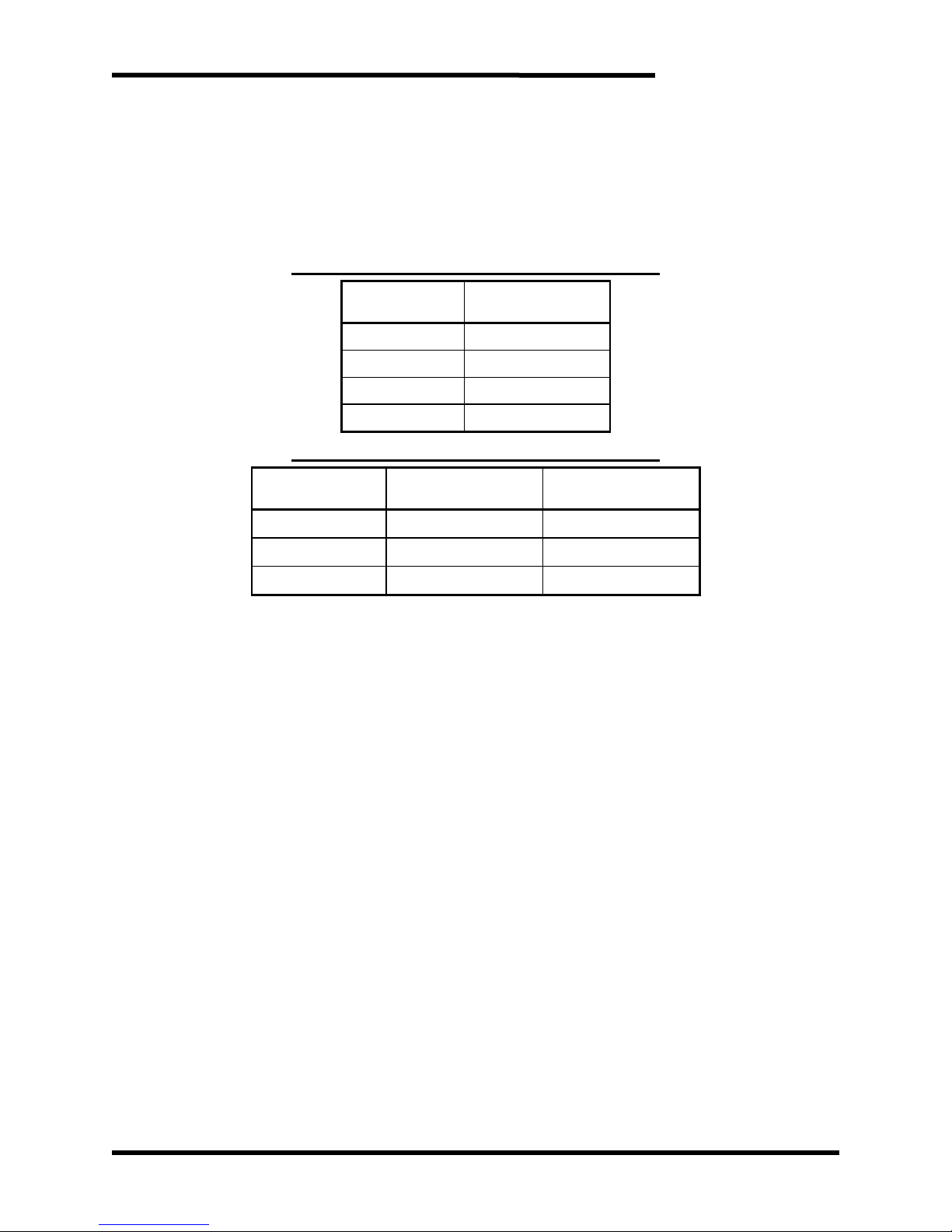
catastrophic damage can occur. Use Tables 6-6 and 6-7 when initially constructing
the system.
Note: AC fuses must be J-type or equivalent.
Table 6-6: Fuse Current Rating Requirements
MODEL
NUMBER
AC / DC FUSE
CURRENT RATING
M3645-x030
40A
M3645-x050
60A
M3645-x100
125A
M3645-x300
350A
Table 6-7: Fuse Voltage Rating Requirements
SYSTEM
VOLTAGE
AC FUSE
VOLTAGE RATING
DC FUSE
VOLTAGE RATING
230–240VAC
240 VAC
350 VDC
380–480VAC
600 VAC
700 VDC
575–600VAC
600 VAC
1000 VDC
Page 44
M3645
44
6.6. DIMENSIONS AND MECHANICAL DRAWINGS
Figure 6-1: M3645 M10 Chassis Dimensional Outline
Page 45
User’s Manual
45
Figure 6-2: M3645 M11 Chassis Dimensional Outline
Page 46
M3645
46
Figure 6-3: M3645 M12 Chassis Dimensional Outline
Page 47
User’s Manual
47
Figure 6-4: M3645 M15 Dimensional Outline
Page 48
M3645
48
Figure 6-5: M645-x300R Line Reactor Dimensional Outline
Page 49
User’s Manual
49
Figure 6-6: KIT 3645DD, External Display Dimensional Outline
5.00
127.0 mm
7.50
190.5 mm
6.83
173.5 mm
4.13
104.8 mm
7.00
177.8 mm
.19
4.8 mm
4.50
114.3 mm
.25
6.4 mm
.25
6.4 mm
R.13
R3.2 mm
R.13
R3.2 mm
n.19
n4.8 mm
.19
4.8 mm
CUTOUT
Page 50
M3645
50
6.7. BLOCK DIAGRAM
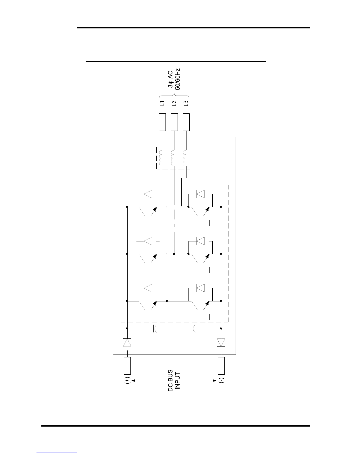
Figure 6-7: M3645 30A, 50A, 100A Functional Block Diagram
Page 51

User’s Manual
51
7. APPENDIX
7.1. APPLICATION NOTES
7.1.1. SIZING THE LINE REGENERATION UNIT
The line regeneration unit is sized for the amount of DC bus current, I
DC,
which
it must carry. To obtain the amount of DC bus current needed during
deceleration; the load and motor inertias, desired change in RPM, and
required stopping time must be known. With these application variables, the
following calculations can be made to size the regen. Use the equation below
to establish the torque required to decelerate or stop a rotating object.
CALCULATE MOTOR TORQUE
Calculating the motor torque
Where
T is torque measured in lb·ft.
1.0 lb·ft = 1.355818 Nm
WK
2
is the total inertial load to be decelerated (lb·ft2).
1.0 lb·ft2 = 0.04214011 kg·m2
ΔN is the change in rotational speed (rpm).
308 is a constant
ton is time required to decelerate the load (s).
CALCULATE MOTOR POWER
Calculating the power (HP) regenerated:
Where
N
max
is the maximum rotational speed (rpm).
The constant 5252 has units of lb·ft/min/radian.
CALCULATE DC BUS CURRENT
Calculating the regenerated DC bus current, IDC.
The DC bus current, IDC, is approximated for the following AC line voltages:
For 230 V
AC
systems:
For 380 V
AC
systems:
For 460 V
AC
systems:
For 575 V
AC
systems:
Once I
DC
is known, you will be able to appropriately size the line regen
based upon its current rating.
Page 52

M3645
52
7.1.2. CALCULATING ENERGY SAVINGS
The regen directs energy from the mechanical load to the power distribution
line, where the energy is available to other connected loads. These units
provide system energy savings over dynamic braking kits, because the net
energy required from the distribution system is reduced by the regenerated
energy. Additional savings also come from the lack of a need to provide air
conditioning with a dynamic braking kit and from reduced time spent stopping
loads.
To calculate the savings, the regeneration duty cycle, the length of operation,
the regen HP, and the cost of energy must be known. With these application
variables, the following calculation may be made to determine the cost
savings:
CALCULATE SAVINGS PER YEAR
Calculating total savings per year in dollars:
Where
S is Savings per year.
C is the cost in dollars per kW.
P is the regenerated power.
D is the number of days the system is operated.
H is the number of hours per day the system is operated.
ton is the number of seconds per cycle T power is regenerated.
t
cycle
is the total time to complete a cycle.
SAVINGS EXAMPLE
Assume the following values for this example:
C = $0.11 per kW
P = 20HP peak, 15HP average during deceleration
D = 365 days
H = 10 hours per day
t
on
= 5 seconds regen is on
t
cycle
= 15 seconds
Savings:
Page 53

User’s Manual
53
NOTES
Page 54

M3645
54
Page 55

Page 56

D_M3645_CMAN_vall_02f 07/12/2016
521 Fairground Court ● Nashville, TN 37211 ● USA
 Loading...