

Page 1

Model M3545P
Regenerative
DC Bus Power Supply
Customer Reference Manual
Page 2

Bonitron, Inc.
2
Bonitron, Inc.
Nashville, TN
An industry leader in providing solutions for AC drives.
ABOUT BONITRON
Bonitron designs and manufactures quality industrial electronics that improve the reliability of
processes and variable frequency drives worldwide. With products in numerous industries, and
an educated and experienced team of engineers, Bonitron has seen thousands of products
engineered since 1962 and welcomes custom applications.
With engineering, production, and testing all in the same facility, Bonitron is able to ensure its
products are of the utmost quality and ready to be applied to your application.
The Bonitron engineering team has the background and expertise necessary to design, develop,
and manufacture the quality industrial electronic systems demanded in today’s market. A strong
academic background supported by continuing education is complemented by many years of
hands-on field experience. A clear advantage Bonitron has over many competitors is combined
on-site engineering labs and manufacturing facilities, which allows the engineering team to have
immediate access to testing and manufacturing. This not only saves time during prototype
development, but also is essential to providing only the highest quality products.
The sales and marketing teams work closely with engineering to provide up-to-date information
and provide remarkable customer support to make sure you receive the best solution for your
application. Thanks to this combination of quality products and superior customer support,
Bonitron has products installed in critical applications worldwide.
Page 3

Bonitron, Inc.
3
AC DRIVE OPTIONS
In 1975, Bonitron began working with AC inverter drive specialists at synthetic fiber plants to
develop speed control systems that could be interfaced with their plant process computers. Ever
since, Bonitron has developed AC drive options that solve application issues associated with
modern AC variable frequency drives and aid in reducing drive faults. Below is a sampling of
Bonitron’s current product offering.
WORLD CLASS PRODUCTS
Undervoltage Solutions
Overvoltage Solutions
Uninterruptible Power for Drives
(DC Bus Ride-Thru)
Voltage Regulators
Chargers and Dischargers
Energy Storage
Braking Transistors
Braking Resistors
Transistor/Resistor Combo
Line Regeneration
Dynamic Braking for Servo Drives
Common Bus Solutions
Portable Maintenance Solutions
Single Phase Power Supplies
3-Phase Power Supplies
Common Bus Diodes
Capacitor Formers
Capacitor Testers
Power Quality Solutions
Green Solutions
12 and 18 Pulse Kits
Line Regeneration
Page 4

M3545P
4
1. INTRODUCTION ..........................................................................................................................7
1.1. Who should use ............................................................................................................................ 7
1.2. Purpose and Scope ........................................................................................................................ 7
1.3. Manual version and change record ............................................................................................... 7
Figure 1-1: Typical M3545P Regenerative Power Supply ....................................................................... 7
1.4. Symbol Conventions Used in this Manual and on Equipment ..................................................... 8
2. PRODUCT DESCRIPTION ............................................................................................................9
2.1. Related Products ........................................................................................................................... 9
2.2. Part Number Breakdown .............................................................................................................. 9
Figure 2-1: Example of M3545P Part Number Breakdown ..................................................................... 9
Table 2-1: Voltage Ratings .................................................................................................................... 10
Table 2-2: Chassis Styles ....................................................................................................................... 10
Table 2-3: Option Codes ........................................................................................................................ 10
2.3. General Specifications Chart ...................................................................................................... 11
Table 2-4: General Specifications .......................................................................................................... 11
2.4. General Precautions and Safety Warnings ................................................................................. 12
3. INSTALLATION INSTRUCTIONS ................................................................................................13
3.1. Environment ............................................................................................................................... 13
3.2. Unpacking ................................................................................................................................... 13
3.3. Mounting .................................................................................................................................... 13
Figure 3-1: M3545P Mounting Orientation ........................................................................................... 14
3.4. Wiring and Customer Connections ............................................................................................. 15
3.4.1. Power Wiring ...................................................................................................................... 15
Table 3-1: Power Terminal Specifications ............................................................................................. 16
Figure 3-2: M3545P Power & I/O Connection Location ....................................................................... 16
3.4.2. I/O Wiring ........................................................................................................................... 17
Table 3-2: M3545P I/O Wiring .............................................................................................................. 17
Figure 3-3: M3545P I/O Diagram .......................................................................................................... 17
3.5. Typical Configurations ............................................................................................................... 17
Figure 3-4: M3545P Power Wiring ........................................................................................................ 18
Figure 3-5: M3545P Multiple Drives Field Wiring Diagram ................................................................. 19
4. OPERATION ..............................................................................................................................21
4.1. Functional Description ............................................................................................................... 21
4.2. Features ....................................................................................................................................... 21
4.2.1. Indicator LEDs .................................................................................................................... 21
4.3. Faults .......................................................................................................................................... 21
4.3.1. Operational Faults ............................................................................................................... 21
Table 4-1: Blink Codes .......................................................................................................................... 22
4.3.2. System Faults ...................................................................................................................... 22
Table 4-2: System Faults ........................................................................................................................ 22
4.4. User I/O Connections ................................................................................................................. 22
4.4.1. N/C (TB-6) .......................................................................................................................... 22
4.4.2. Input COM (TB-7) .............................................................................................................. 22
4.4.3. Fault Recall (TB-8) ............................................................................................................. 22
4.4.4. Output Com (TB-9) ............................................................................................................. 23
4.4.5. Ready (TB-10) .................................................................................................................... 23
4.5. Startup ......................................................................................................................................... 23
4.5.1. Pre-power Checks ............................................................................................................... 23
Page 5

Table of Contents
5
4.5.2. Startup Procedure and Checks ............................................................................................ 23
4.5.3. Cooling Fan ......................................................................................................................... 23
5. MAINTENANCE AND TROUBLESHOOTING ...............................................................................25
5.1. Periodic Testing .......................................................................................................................... 25
5.2. Maintenance Items ...................................................................................................................... 25
5.3. Troubleshooting .......................................................................................................................... 25
5.3.1. POWER LED is not on ....................................................................................................... 25
5.3.2. READY output will not close ............................................................................................. 25
5.3.3. Over Voltage fault on Drive or Regen ................................................................................ 25
5.3.4. Overtemperature Fault ........................................................................................................ 26
5.3.5. IGBT Desat Fault ................................................................................................................ 26
5.3.6. Phase Loss Fault.................................................................................................................. 26
5.3.7. Fuses fail on power on ........................................................................................................ 26
5.4. Technical Help – Before you contact us ..................................................................................... 26
6. ENGINEERING DATA ................................................................................................................27
6.1. Ratings Charts ............................................................................................................................. 27
Table 6-1: Ratings and Specifications – 230 - 240VAC ........................................................................ 27
Table 6-2: Ratings and Specifications – 460 - 480VAC ........................................................................ 27
6.2. Derating Parallel M3545P .......................................................................................................... 27
Table 6-3: Derating M3545P in Parallel ................................................................................................ 27
6.3. Watt Loss .................................................................................................................................... 27
6.4. Certifications .............................................................................................................................. 28
6.4.1. UL 61800-5-1 ...................................................................................................................... 28
6.4.2. RoHS ................................................................................................................................... 28
6.5. Fuse Selection ............................................................................................................................. 28
Table 6-4: Fuse Current Rating Requirements ....................................................................................... 28
6.6. Dimensions and Mechanical Drawings ...................................................................................... 29
Figure 6-1: M3545P M4 Chassis Dimensional Outline ......................................................................... 29
7. APPENDIX .................................................................................................................................31
7.1. Application Notes ....................................................................................................................... 31
7.1.1. Sizing the M3545P .............................................................................................................. 31
7.1.2. Calculating Energy Savings ................................................................................................ 32
Page 6

M3545P
6
This page intentionally left blank
Page 7
User’s Manual
7
1. INTRODUCTION
1.1. WHO SHOULD USE
This manual is intended for use by anyone who is responsible for integrating, installing,
maintaining, troubleshooting, or using this equipment with any AC Drive System.
Please keep this manual for future reference.
1.2. PURPOSE AND SCOPE
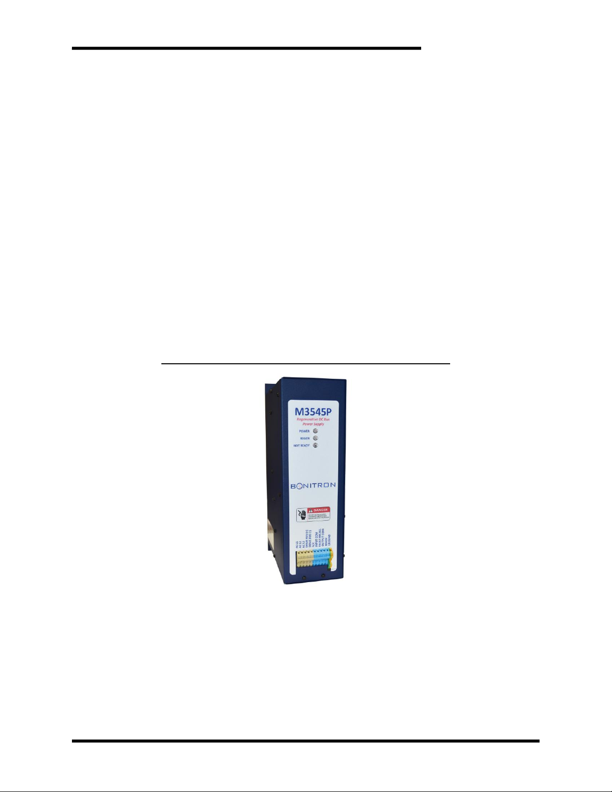
This manual is a user’s guide for the Model M3545P regenerative power supply. It
provides you with the necessary information to successfully install and use the
M3545P unit in your application.
In the event of any conflict between this document and any publication and/or
documentation related to the application, the latter shall have precedence.
1.3. MANUAL VERSION AND CHANGE RECORD
The initial release of the M3545P Line Regen is Rev 00a.
Fuse current ratings and recommended fuses Table 6-4 was updated in Rev 0b.
Updated table 7.1.1 in Rev 00c
Figure 1-1: Typical M3545P Regenerative Power Supply
Page 8
M3545P
8
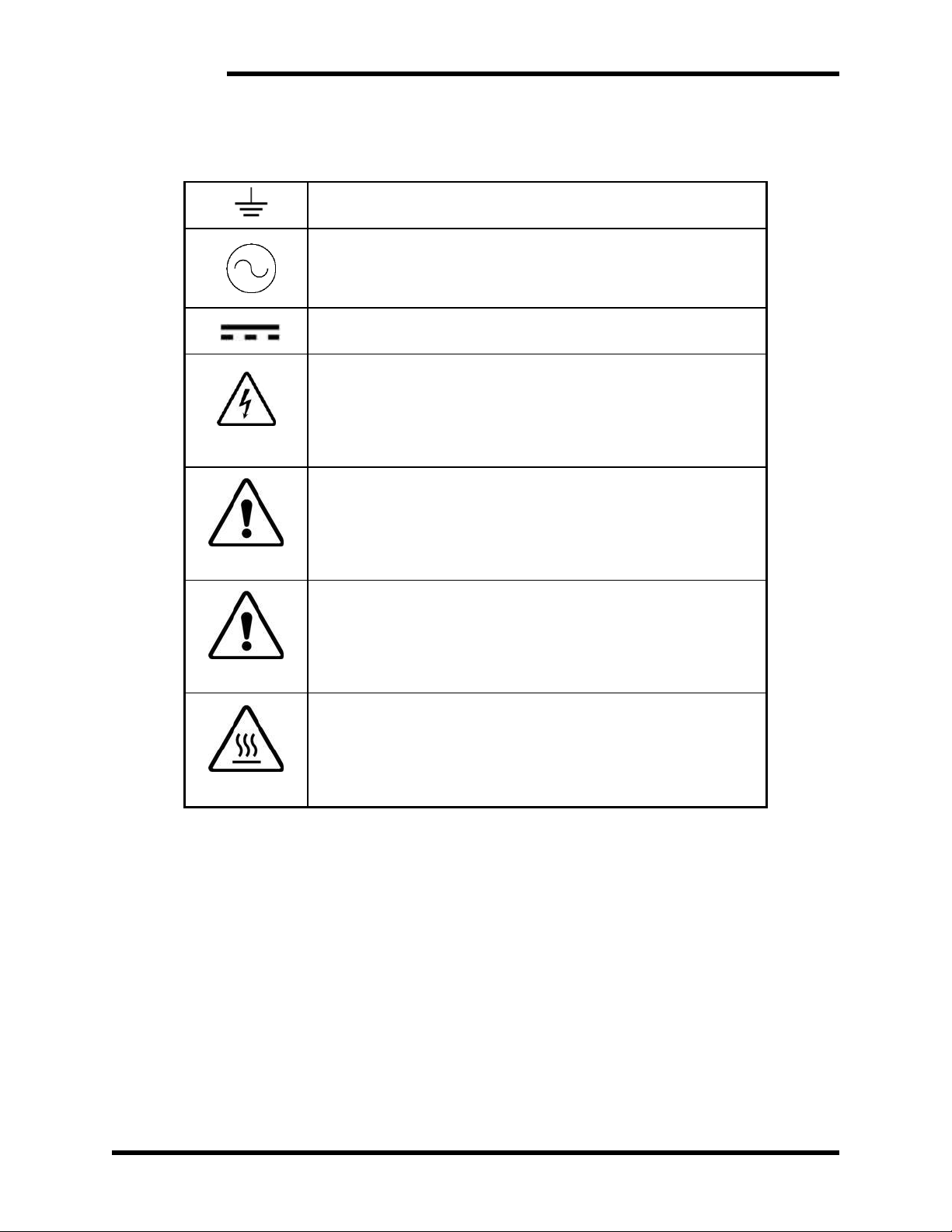
1.4. SYMBOL CONVENTIONS USED IN THIS MANUAL AND ON
EQUIPMENT
Earth Ground or Protective Earth
AC Voltage
DC Voltage
DANGER!
DANGER: Electrical hazard - Identifies a statement that indicates
a shock or electrocution hazard that must be avoided.
DANGER!
DANGER: Identifies information about practices or circumstances
that can lead to personal injury or death, property damage, or
economic loss.
CAUTION!
CAUTION: Identifies information about practices or
circumstances that can lead to property damage, or economic
loss. Attentions help you identify a potential hazard, avoid a
hazard, and recognize the consequences.
CAUTION!
CAUTION: Heat or burn hazard - Identifies a statement regarding
heat production or a burn hazard that should be avoided.
Page 9
User’s Manual
9
OPTION CODE
R
2. PRODUCT DESCRIPTION
The M3545P Regenerative DC Power Supply is a bi-directional power supply. During
normal operation it sources energy to the drive through the DC bus. If the DC bus voltage
begins to rise, due to the drive trying to brake or an overhauling load, the M3545P will sink
energy back to the AC Line. Under motoring conditions, the M3545P rectifies the AC line
and supplies power to the drive through its DC bus terminals.
Alternative resistive braking solutions simply dissipate this regenerated energy as heat.
Bonitron’s M3545P returns the regenerated energy back to the AC line, making it
particularly well suited for applications with frequent or extended duration braking events.
Additionally, the M3545P is designed to be able to operate on both single-phase and
three-phase AC grids, at either 50Hz or 60Hz line frequency.
2.1. RELATED PRODUCTS
COMMON BUS DIODES
• M3345CBM Sharing Diode
BRAKING RESISTORS
• M3575R Standard Duty Braking Resistors (<30A)
• M3775R Various Duty Load Banks (<1600A)
BRAKING TRANSISTORS
• M3452 Heavy Duty Braking Transistor (<1600A)
• M3575T Standard Duty Braking Transistor (<600A)
• M3675T Low HP Braking Transistor (<10A)
THREE PHASE POWER SUPPLIES
• M3713DM Non-Regenerative Power Supply (<375A)
• M3713SC Non-Regenerative Power Supply with Precharge (<375A)
LINE REGEN
• M3545 Single Phase or Three Phase Line Regen (<15A)
• M3645 Heavy Duty Line Regen (<375A)
RESISTIVE PRECHARGE
• M3728 Precharge Module
2.2. PART NUMBER BREAKDOWN
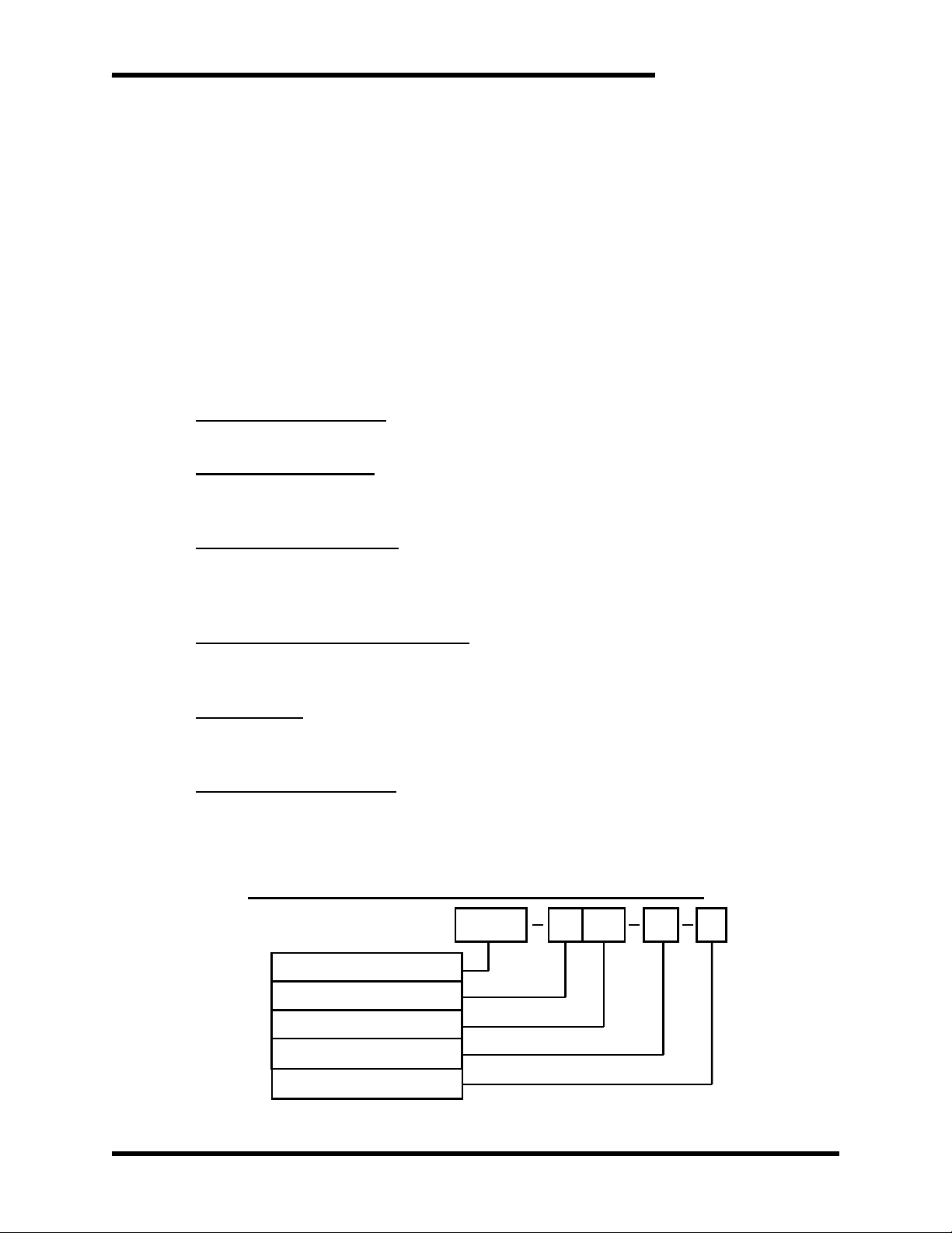
Figure 2-1: Example of M3545P Part Number Breakdown
M3545P
H
015
M4
BASE MODEL NUMBER
VOLTAGE RATING
CURRENT RATING
CHASSIS STYLE
Page 10

M3545P
10
BASE MODEL NUMBER
The Base Model Number for these regenerative power supply is M3545P.
VOLTAGE RATING
A code letter represents the AC line voltage of the power supply module. The voltage
rating must be selected for the system voltage that will be applied. See Table 2-1 for
available voltage ratings.
Table 2-1: Voltage Ratings
RATING CODE
VOLTAGE
L
230 - 240VAC
H
460 - 480VAC
CURRENT RATING
A 3-digit number represents the maximum continuous DC current (Amps) the unit can
regenerate. Each unit is capable of handling a 50% overload above this current rating
for 60 seconds.
CHASSIS STYLE
The Chassis Style is determined by the current rating, and is represented by an
alphanumeric code as defined in Table 2-2.
Table 2-2: Chassis Styles
CHASSIS CODE
CURRENT
DESCRIPTION
SIZE (H X W X D)
M4
15A
Open Chassis
17.0” x 4.7” x 10.8”
See Section 6.5 for chassis mounting and dimensional outlines.
OPTION CODE
The available option codes are listed in Table 2-3.
Table 2-3: Option Codes
OPTION CODE
DESCRIPTION
R
Precharge (required for VFDs without
precharge on DC terminals)
Page 11

User’s Manual
11
2.3. GENERAL SPECIFICATIONS CHART
Table 2-4: General Specifications
PARAMETER
SPECIFICATION
AC Line Voltage
• 230 - 480 VAC ±10% 50/60Hz
DC Input Current
3-Phase Operation
• 15A, continuous
• 22.5A for 60 second overload
1-Phase Operation
• 5A, continuous
• 7.5A for 60 second overload
Maximum Load
Capacitance
• 10,000 uF (-R option only)
Indicators
• 3 Status LEDs
• Power, Regen, Not Ready
Inputs
• Fault Blink
o 24VDC - 5mA
Outputs
• Ready
o Normally Open, Solid State Relay
Operating Temp
• 0 to +40OC
Storage Temp
• -20O to +65OC
Humidity
• Below 90%, non-condensing
Atmosphere
• Free of corrosive gas or conductive dust
Page 12
M3545P
12
2.4. GENERAL PRECAUTIONS AND SAFETY WARNINGS
DANGER!
• HIGH VOLTAGES MAY BE PRESENT!
• NEVER ATTEMPT TO OPERATE THIS PRODUCT WITH THE ACCESS
DOORS OR COVERS OPENED!
• NEVER ATTEMPT TO SERVICE THIS PRODUCT WITHOUT FIRST
DISCONNECTING POWER TO AND FROM THE UNIT!
• FAILURE TO HEED THESE WARNINGS MAY RESULT IN
SERIOUS BODILY INJURY OR DEATH!
CAUTION!
• THIS PRODUCT WILL GENERATE HIGH AMBIENT TEMPERATURES
DURING OPERATION.
• THIS PRODUCT SHOULD BE INSTALLED ON A NON-FLAMMABLE
SURFACE WITH CLEARANCES OF AT LEAST TWO INCHES IN ALL
DIRECTIONS.
• ALWAYS ALLOW AMPLE TIME FOR THE UNIT TO COOL BEFORE
ATTEMPTING SERVICE ON THIS PRODUCT.
• BEFORE ATTEMPTING INSTALLATION OR REMOVAL OF THIS
PRODUCT, BE SURE TO REVIEW ALL DRIVE AND/OR RESISTIVE
LOAD DOCUMENTATION FOR PERTINENT SAFETY PRECAUTIONS.
• INSTALLATION AND/OR REMOVAL OF THIS PRODUCT SHOULD
ONLY BE ACCOMPLISHED BY A QUALIFIED ELECTRICIAN IN
ACCORDANCE WITH NATIONAL ELECTRICAL CODE OR
EQUIVALENT REGULATIONS.
ANY QUESTIONS AS TO APPLICATION, INSTALLATION OR SERVICE
SAFETY SHOULD BE DIRECTED TO THE EQUIPMENT SUPPLIER.
Page 13

User’s Manual
13
3. INSTALLATION INSTRUCTIONS
CAUTION!
Installation and/or removal of this product should only be performed by a
qualified electrician in accordance with National Electrical Code or local
codes and regulations.
Proper installation of the M3545P regenerative power supply modules should be
accomplished following the steps outlined below. Be sure to refer to the AC drive instruction
manual as these steps are performed. Please direct all installation inquiries that may arise
during the installation and start-up of this product to the equipment supplier or system
integrator.
3.1. ENVIRONMENT
The module should be installed in an area protected from moisture and falling debris.
Buildup of dust or debris may cause poor performance and possibly a failure.
Operating in a wet environment can pose a shock hazard. The recommended
temperature range for operating this module is 0 to +40C.
3.2. UNPACKING
Upon receipt of this product, please verify that the product received matches the
product that was ordered and that there is no obvious physical damage to the unit. If
the wrong product was received or the product is damaged in any way, please contact
the supplier from which the product was purchased.
3.3. MOUNTING
The installation site for the module should be chosen with several considerations in
mind:
• When mounting the units in an enclosure, power dissipation should be taken into
account. Refer to Section 6.2 Watt Loss for details.
• The unit requires a minimum clearance of two (2) inches in all directions around it
when not mounted near a heat source. Heat sources may increase necessary
clearances.
• Unit should not be exposed to falling debris or condensation.
Once the installation site has been selected as outlined above, the unit should be
mounted in place.
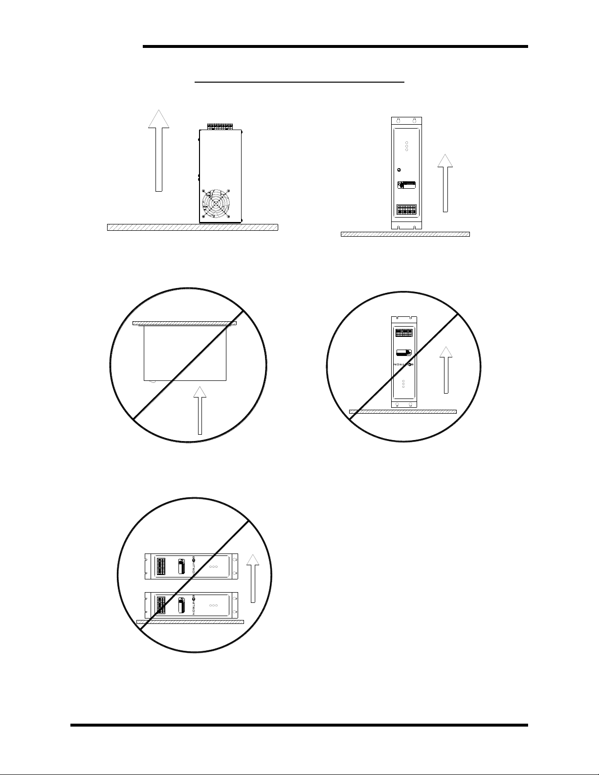
The M3545P must be correctly oriented for proper heat flow through the unit. The
M3545P must be mounted with the rear surface of the unit to the mounting surface.
The unit may be mounted vertically or horizontally as shown in Figure 3-1A and 3-1D.
Do Not mount the unit in an upside-down position or on the underside of a mounting
surface as shown in Figure 3-1B and 3-1E.
Do Not mount the unit in a horizontal position with its side parallel to the mounting
surface or floor as shown in Figure 3-1C.
See Figure 6-1 for dimensional outline.
Page 14
M3545P
14
Figure 3-1: M3545P Mounting Orientation
Figure 3-1A
Figure 3-1D
HORIZONTAL SURFACE
UP
UP
UP
M3545
Line Regen
POWER
REGEN
NOT READY
140040
AC L1
AC L2
AC L3
DRIVE BUS (+)
DRIVE BUS (-)
INPUT COM
FAULT RECALL
OUTPUT COM
READY
GROUND
N/C
RISK OF ELECTRICAL SHOCK.
DISCONNECT INPUT POWER
BEFORE SERVICING EQUIPMENT.
M3545
Line Regen
POWER
REGEN
NOT READY
B NITRON
140040
AC L1
AC L2
AC L3
DRIVE BUS (+)
DRIVE BUS (-)
INPUT COM
FAULT RECALL
OUTPUT COM
READY
GROUND
N/C
RISK OF ELECTRICAL SHOCK.
DISCONNECT INPUT POWER
BEFORE SERVICING EQUIPMENT.
Figure 3-1B
Figure 3-1E
UP
HANGING UNDERSIDE
UP
M3545
Line Regen
POWER
REGEN
NOT READY
140040
AC L1
AC L2
AC L3
DRIVE BUS (+)
DRIVE BUS (-)
INPUT COM
FAULT RECALL
OUTPUT COM
READY
GROUND
N/C
RISK OF ELECTRICAL SHOCK.
DISCONNECT INPUT POWER
BEFORE SERVICING EQUIPMENT.
Figure 3-1C
UP
PARALLEL TO FLOOR
UP
M3545
Line Regen
POWER
REGEN
NOT READY
140040
AC L1
AC L2
AC L3
DRIVE BUS (+)
DRIVE BUS (-)
INPUT COM
FAULT RECALL
OUTPUT COM
READY
GROUND
N/C
RISK OF ELECTRICAL SHOCK.
DISCONNECT INPUT POWER
BEFORE SERVICING EQUIPMENT.
M3545
Line Regen
POWER
REGEN
NOT READY
B NITRON
140040
AC L1
AC L2
AC L3
DRIVE BUS (+)
DRIVE BUS (-)
INPUT COM
FAULT RECALL
OUTPUT COM
READY
GROUND
N/C
RISK OF ELECTRICAL SHOCK.
DISCONNECT INPUT POWER
BEFORE SERVICING EQUIPMENT.
M3545
Line Regen
POWER
REGEN
NOT READY
140040
AC L1
AC L2
AC L3
DRIVE BUS (+)
DRIVE BUS (-)
INPUT COM
FAULT RECALL
OUTPUT COM
READY
GROUND
N/C
RISK OF ELECTRICAL SHOCK.
DISCONNECT INPUT POWER
BEFORE SERVICING EQUIPMENT.
M3545
Line Regen
POWER
REGEN
NOT READY
140040
AC L1
AC L2
AC L3
DRIVE BUS (+)
DRIVE BUS (-)
INPUT COM
FAULT RECALL
OUTPUT COM
READY
GROUND
N/C
RISK OF ELECTRICAL SHOCK.
DISCONNECT INPUT POWER
BEFORE SERVICING EQUIPMENT.
Page 15

User’s Manual
15
3.4. WIRING AND CUSTOMER CONNECTIONS
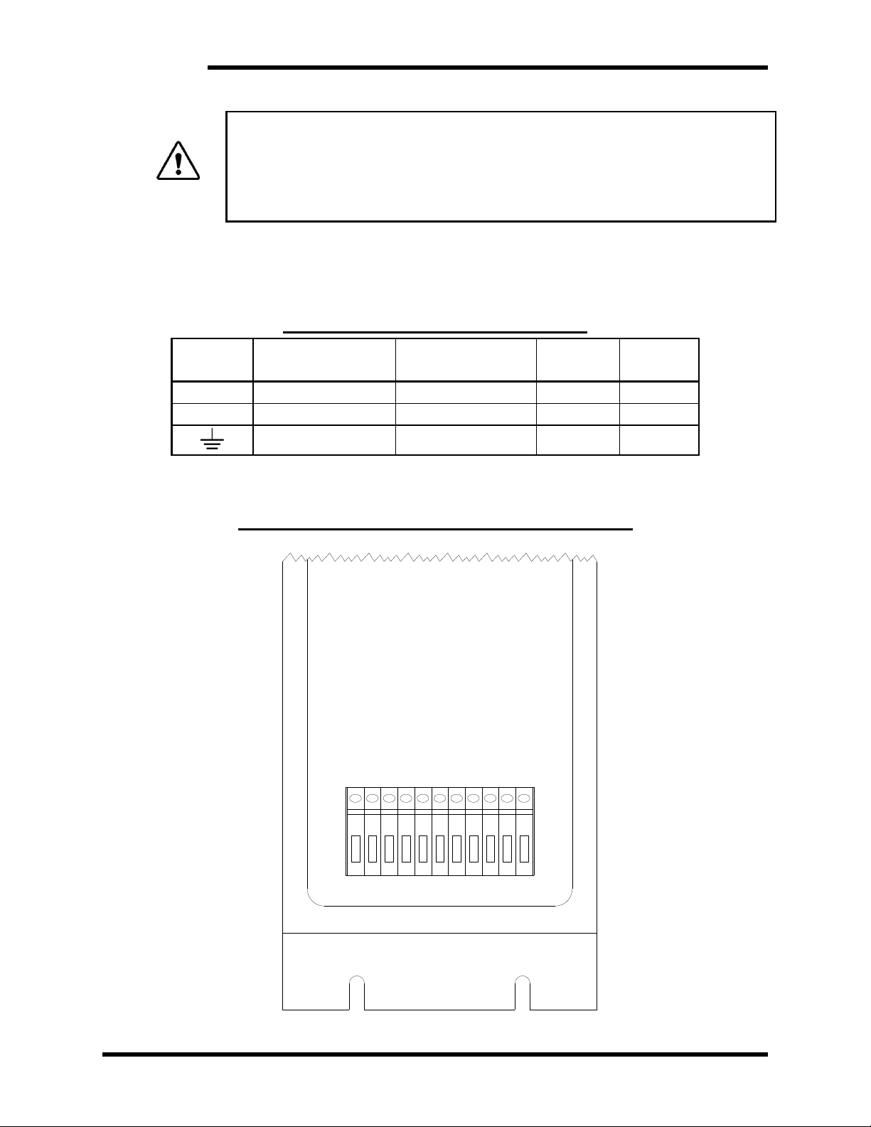
All power and user I/O wiring connections are brought out to the terminal block in the
front face of the unit; there should be no need to open the chassis during installation.
Be sure to review all pertinent AC drive and system documentation as well as the
information listed below before proceeding. Connection points and terminal numbers
of the AC drive will be found in the documentation provided with those units.
See Tables 3-1 and 3-2 and Figures 3-2 through 3-5 for connection details.
3.4.1. POWER WIRING
Power connections are on the terminal block on TB-1 through TB-5. See
Figure 3-2.
▪ Where possible, minimize the DC wire length between the M3645P and
the drive. The wire length should not exceed 10 feet.
▪ Avoid routing and bundling the unit’s AC/DC wire along with the drive
output leads to the motor.
CAUTION!
Only qualified electricians should perform and maintain the interconnection
wiring of this product. All wiring should be in accordance with local codes.
3.4.1.1. AC LINE
• The AC Line connections should be to a source rated for at least 150%
of the continuous current rating. This will ensure sufficient source
impedance to return power to the grid.
• Do not install any external chokes or reactors between the M3545P and
the power source; the M3545P has an internal 5% reactor.
• A properly rated isolation transformer may be installed between the
M3545P and the power source, if desired.
• Do not connect to a generator unless minimum load at any time exceeds
the peak expected regen power.
• The M3545P units are not phase sensitive.
• The AC Line connections should have short-circuit current protection.
See Table 6-3.
• To use the M3545P on a single-phase AC grid, you MUST connect to AC
L1 (TB-1) and AC L2 (TB-2).
3.4.1.2. DC BUS
• The DC bus connections may be made to the DC bus of an AC drive, the
DC output of a diode sharing unit, or to a common DC bus.
o If a reactor or choke are being used in the bus, make sure the actual
connection is in parallel with filter capacitors of the drive/inverter.
• The DC bus connections should have short-circuit current protection.
The recommended fuses are listed in Table 6-3.
Page 16
M3545P
16
DANGER!
Never attach the DC bus input of the M3545P to braking terminals on the AC
drive, commonly marked “BR”. These terminals are intended for use with an
external resistor, and are not directly connected to the bus filter capacitors of
the drive. Damage may occur if these terminals are used.
Please refer to your AC drive manual or AC drive technical support department
for assistance with this connection.
3.4.1.3. GROUNDING
Using the GND TB-11 on the terminal block, ground the chassis in
accordance with local codes. Typically, the wire gauge will be the same
as is used to ground the attached drive.
Table 3-1: Power Terminal Specifications
TERMINALS
FUNCTION
ELECTRICAL
RATINGS
WIRE SIZE
TORQUE
L1, L2, L3
AC line
15A
12 AWG
7 lb-in
DC+, DC-
DC bus
15A
12 AWG
7 lb-in
Ground
12 AWG
7 lb-in
Note: All power wire should be selected to match or exceed the voltage rating of the M3545P.
Ground wiring should be, at smallest, one gauge smaller than the selected power wiring.
Figure 3-2: M3545P Power & I/O Connection Location
AC L1
AC L2
AC L3
DRIVE BUS (+)
DRIVE BUS (-)
INPUT COM
FAULT RECALL
OUTPUT COM
READY
N/C
GROUND
Page 17
User’s Manual
17
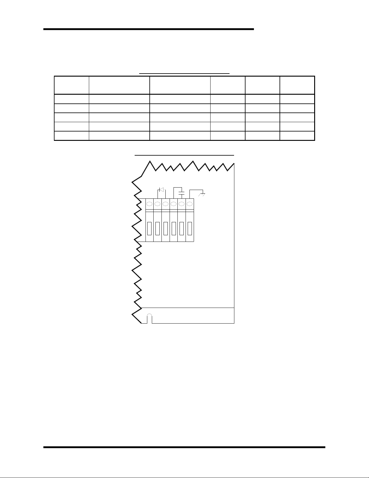
3.4.2. I/O WIRING
User I/O is connected on the terminal block to TB-6 through TB-10.
Table 3-2: M3545P I/O Wiring
TERMINALS
FUNCTION
ELECTRICAL
RATINGS
WIRE SIZE
MINIMUM
WIRE SIZE
MAXIMUM
TORQUE
TB-6
N/C
TB-7
Input COM
COM to TB-8
18
16
2.2 lb-in
TB-8
Fault Recall
24VDC, 5mA
18
16
2.2 lb-in
TB-9
Output COM
COM to TB-10
18
16
2.2 lb-in
TB-10
Ready
150VAC, 150mA
18
16
2.2 lb-in
Figure 3-3: M3545P I/O Diagram
GROUND
READY
OUTPUT COM
N/C
FAULT RECALL
INPUT COM
3.5. TYPICAL CONFIGURATIONS
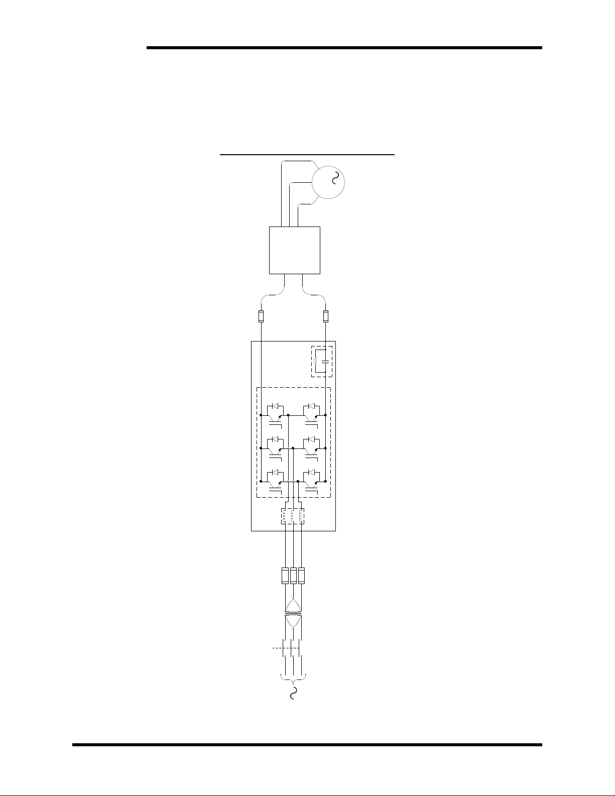
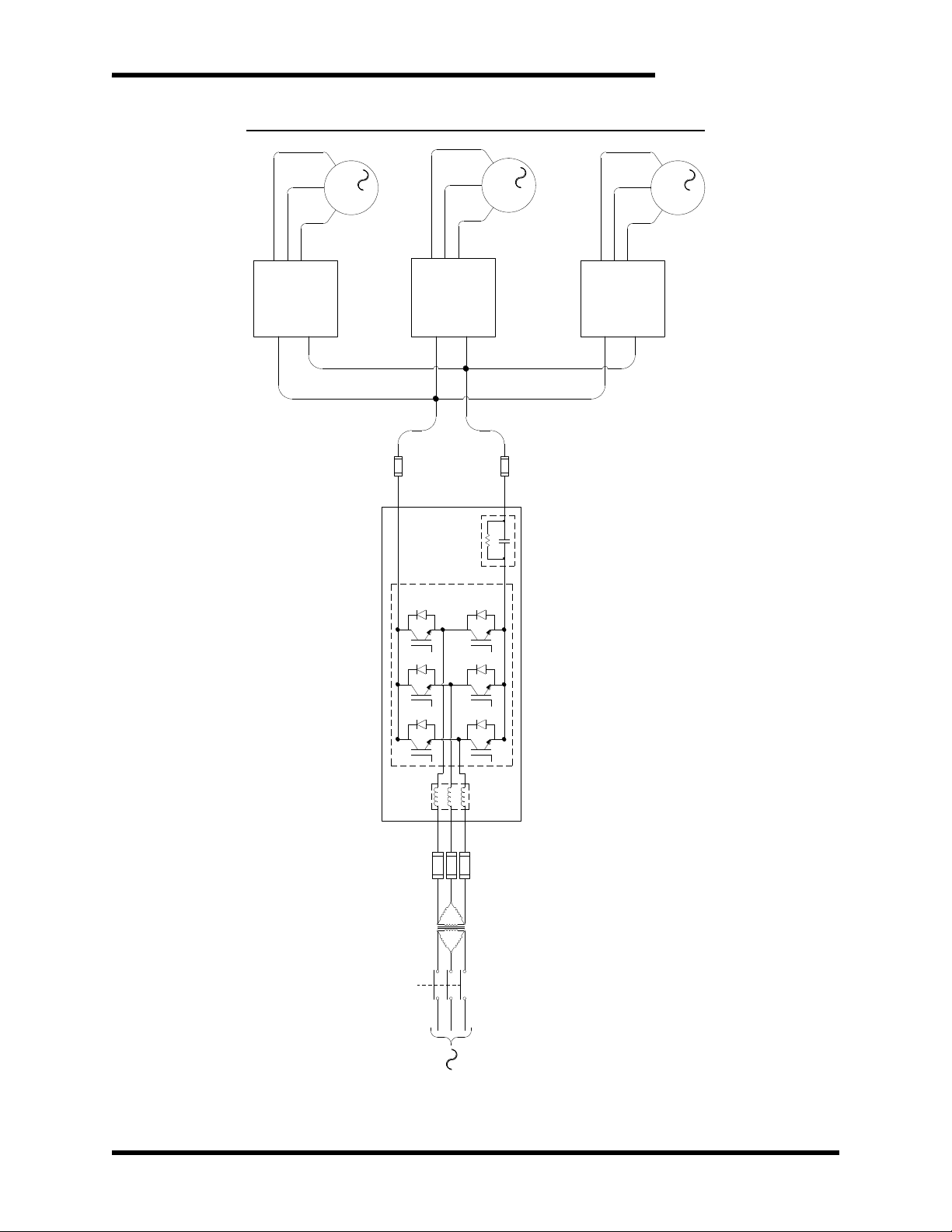
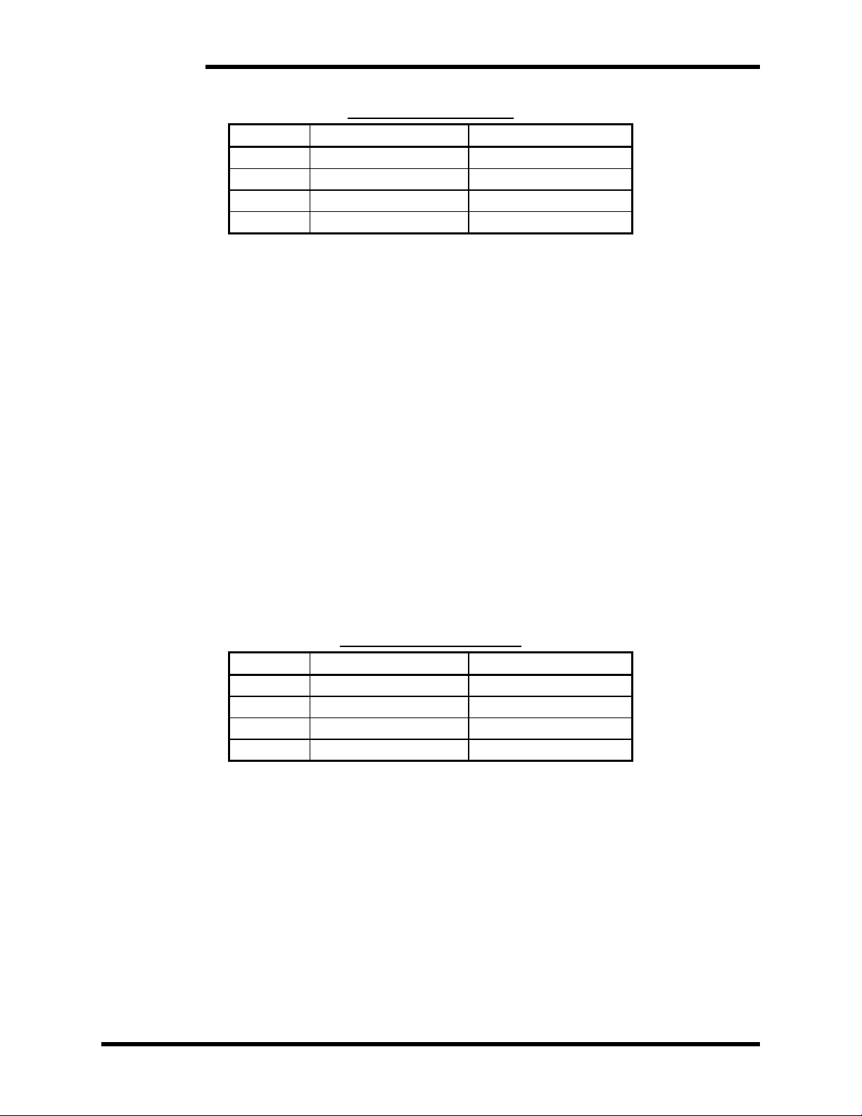
The diagrams shown in Figure 3-4 and Figure 3-5 illustrate typical connections of the
M3545P units with generic VFDs. There are many other configurations that may be
applied provided a basic connection criterion is maintained such as:
• The AC Line connections should maintain a low impedance path back to the grid.
• No reactors should be connected upstream of the M3545P unit without consulting
Bonitron for instructions.
• The DC link should be connected to a fixed bus whether from a common bus
supply or from the output of a VFD. This should never be connected to a switching
source such as the braking resistor terminals on some drives.
• The DC link should not be connected to an active front end drive without
instructions from Bonitron.
Page 18
M3545P
18
• Any capacitive load requires precharge. Ensure that either the load has internal
precharge, or that the M3545P unit has a –R option. Units without the –R option
do not support precharge of any amount of capacitance. Applying power with no
precharge in the system will result in fuse failure, and possible damage to the unit
and load.
Figure 3-4: M3545P Power Wiring
Disconnect
Isolation
Transformer
(if used)
3
M
3
DC+
DC-
INVERTER
Precharge
"R" Option
Only
Page 19
User’s Manual
19
Figure 3-5: M3545P Multiple Drives Field Wiring Diagram
M
3
Disconnect
Isolation
Transformer
(if used)
3
M
3
M
3
DC+
DC-
DC+
DC-
DC+
DC-
INVERTER
INVERTER
INVERTER
Precharge
"R" Option
Only
Page 20

M3545P
20
This page intentionally left blank
Page 21

User’s Manual
21
4. OPERATION
4.1. FUNCTIONAL DESCRIPTION
The M3545P regenerative power supply can power one or more drives through the
DC bus. During motoring, the unit acts as a simple diode bridge rectifier with an
internal 5% reactor. M3545P units with an –R option code will precharge a capacitive
load, up to their maximum specified load capacitance. Units without this code can only
be used with drives that can precharge from their DC terminals.
If the DC voltage begins to rise, due to braking or an over-hauling motor, the M3545P
acts as a 6-pulse inverter to efficiently sink this excess energy back to the power grid.
The M3545P is regen current-limited; it will fold back if the regen currents rise to unsafe
levels. Fault conditions are monitored and stored in persistent memory and the last
fault state can be shown on the fault indicator.
4.2. FEATURES
4.2.1. INDICATOR LEDS
4.2.1.1. POWER – GREEN LED
Indicates that the AC voltage is present at the unit and the unit is powered
on.
4.2.1.2. REGEN ACTIVE – YELLOW LED
This means the unit is actively regenerating. Current is flowing from the
drive DC bus out to the AC line.
4.2.1.3. NOT READY – RED LED
This indicates when there is a problem with the unit.
FLASHING RED means that a fault has occurred. The number of flashes
indicates the specific fault(s) (see Table 4-1).
4.3. FAULTS
The Ready Output contact will be open while the unit is in a faulted state.
4.3.1. OPERATIONAL FAULTS
The M3545P monitors several internal parameters during operation. If any of
them deviate beyond their safe boundaries, the M3545P will halt operation
and blink a fault code to indicate the nature of the problem. These faults are
indicated by a FLASHING RED LED.
All of these faults, with the exception of IGBT Desat, will auto clear so that
the unit can resume operation as soon as it is safe to do so.
Page 22
M3545P
22
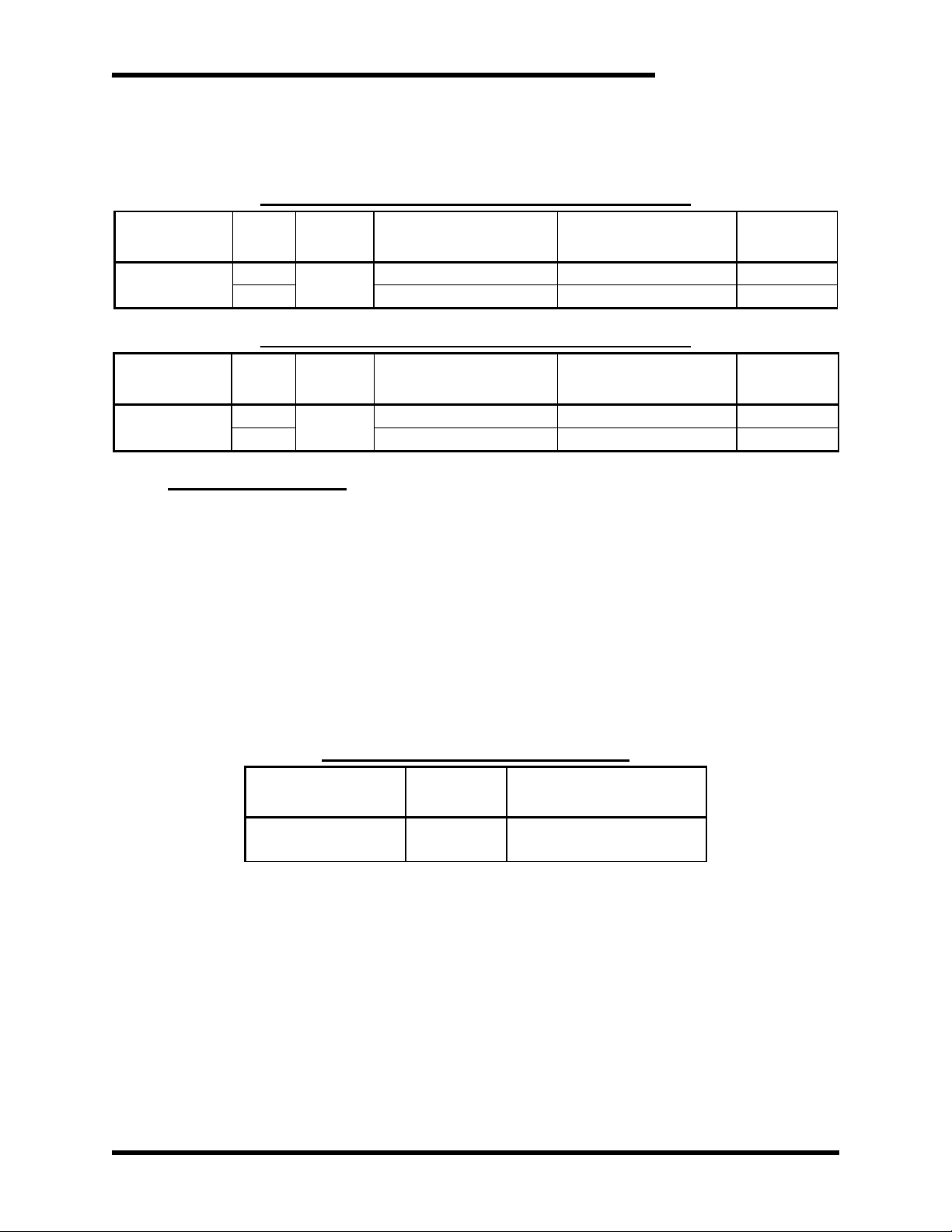
Table 4-1: Blink Codes
FLASHES
FAULT
AUTO CLEAR
1
Phase Loss
Yes
2
Over Temp
Yes
3
Over Voltage
Yes
4
IGBT Desat
No
4.3.1.1. PHASE LOSS
Phase Loss fault indicates that the unit has lost feedback from L3 on the AC
connections. This fault clears itself 10 seconds after the condition is cleared.
4.3.1.2. OVER TEMP
Over Temp fault indicates that some internal components have exceeded
their operating temperatures. This fault will clear after the unit cools down.
4.3.1.3. OVER VOLTAGE
Over Voltage fault occurs when the internal DC bus voltage rises to unsafe
levels during operation. This fault clears itself 10 seconds after the condition
is cleared.
4.3.1.4. IGBT DESAT
This fault indicates the internal transistor drive circuitry has detected an error.
This fault must be manually cleared as it usually indicates a failure elsewhere
in the system.
4.3.2. SYSTEM FAULTS
Additionally, there are several system faults that indicate the
microprocessor has encountered a critical error. These faults are indicated
by a SOLID RED LED and a FLASHING YELLOW LED.
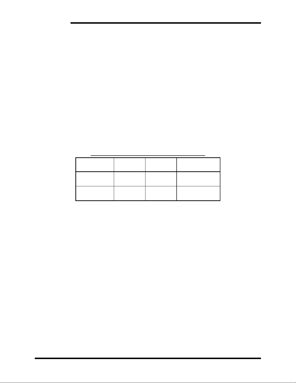
Table 4-2: System Faults
FLASHES
PROCESSOR ERROR
AUTO CLEAR
1
Clock
No
2
Address
No
3
Stack
No
4
Math
No
4.4. USER I/O CONNECTIONS
All of the user inputs to the M3545P are 24VDC, active-high logic, and must be
referenced to TB-7. The outputs are dry contacts that close to the output common:
TB-9.
4.4.1. N/C (TB-6)
This is a spare input reserved for future use and has no function at this time.
4.4.2. INPUT COM (TB-7)
All user inputs are referenced to this terminal.
4.4.3. FAULT RECALL (TB-8)
Activating this input while the unit is idle will cause it to blink out the most
recent fault state.
Page 23

User’s Manual
23
4.4.4. OUTPUT COM (TB-9)
The output contact closes to this terminal
4.4.5. READY (TB-10)
This output closes to TB-9 when the M3545P is ready to operate. This contact
will open if the unit is faulted.
4.5. STARTUP
This section covers basic checks and procedures that should be used when
performing a startup with a M3545P regenerative power supply.
CAUTION!
Multiple repeated precharge cycles can damage the M3545’s precharge
resistor. Ensure that no more than five precharge cycles take place within a
five minute span.
4.5.1. PRE-POWER CHECKS
▪ Verify that the voltage of the AC power system is the same as the unit.
▪ Ensure that all connections are tight and that all wiring is of the proper
size and rating for operation.
▪ Verify continuity of all fuses prior to applying power.
▪ Check for exposed conductors that may lead to inadvertent contact.
▪ Check for any debris, shavings, trimmings, etc. that may cause shorts or
obstruct ventilation on unit.
4.5.2. STARTUP PROCEDURE AND CHECKS
After completing pre-checks and recommended checks for connected
equipment you may apply power to the system.
▪ The green Power LED should light up and stay on. This indicates that
the regenerative power supply is powered on.
▪ Both red and yellow indicator LEDs should illuminate on the front panel
and the fan should turn on for 3 sec.
▪ The red and yellow LEDs will then toggle once or three times to indicate
how many AC phases the unit has detected.
▪ Finally, the Not Ready and Regen Active LEDs should turn off and the
Ready Output contact will close.
The drive system can now be run normally.
4.5.3. COOLING FAN
The cooling fan runs when the unit is active (braking event), and stays on for
10 minutes after the active event ends. If the unit gets too hot, the fan will
stay running until the unit’s internal temperature falls below the threshold.
Page 24

M3545P
24
This page intentionally left blank
Page 25

User’s Manual
25
5. MAINTENANCE AND TROUBLESHOOTING
Repairs or modifications to this equipment are to be performed by Bonitron approved
personnel only. Any repair or modification to this equipment by personnel not approved
by Bonitron will void any warranty remaining on this unit.
5.1. PERIODIC TESTING
While there are no requirements for periodic testing of these units, it may be beneficial
to repeat the start-up checks when performing routine maintenance on other drive
components in the system.
5.2. MAINTENANCE ITEMS
Check the fan periodically for debris, and blow out with an air hose if it has become
obstructed or not running at full capacity. Power should not be applied when
blowing dust and debris out of unit.
5.3. TROUBLESHOOTING
CAUTION!
There are no user serviceable parts within the M3545P. If you are still
experiencing problems after you have reviewed this whole section you may
contact Bonitron for additional assistance at (615) 244-2825.
5.3.1. POWER LED IS NOT ON
▪ Check the AC voltage at the terminals of the M3545P. Voltage should
be within the range specified for your unit. (See Section 2.)
▪ Check any overcurrent devices or disconnects in the AC line upstream of
the M3545P.
▪ It is possible that the unit has been damaged and will need repairs.
5.3.2. READY OUTPUT WILL NOT CLOSE
The Ready output indicates that the module is ready to operate. It should
only be open when the unit is faulted.
▪ Make sure the Power LED is on.
▪ If the Fault LED is FLASHING, refer to Section 4.3 to determine what fault
conditions are present.
5.3.3. OVER VOLTAGE FAULT ON DRIVE OR REGEN
If the attached drive regularly trips during braking, the unit is most likely not
operating. There are some simple things to check to determine the cause:
▪ Check the DC bus voltage at fuses.
▪ Check the DC bus polarity at fuses.
▪ Verify the DC link fuses have not cleared.
▪ Make sure the M3545P is powered on. The Ready Output should close
when the unit is ready to operate.
▪ Any faults that occur will prevent the unit from running. Check the Fault
LED and clear any existing fault conditions
Page 26

M3545P
26
5.3.4. OVERTEMPERATURE FAULT
▪ Ensure there is adequate clearance and airflow around the installation
location.
▪ Check the ambient temperature. If it is above 40C, the unit may not be
able to properly cool at full load.
▪ Make sure the fan is actually operating.
o The fan should be running when the unit is Active (yellow LED lit).
o Check for any obstructions and cycle power to the unit. The fan
should run for three (3) seconds during start-up.
5.3.5. IGBT DESAT FAULT
If the fault cannot be cleared, or occurs frequently, the unit may be damaged.
Contact Bonitron for assistance.
5.3.6. PHASE LOSS FAULT
If this fault does not reset, it typically means the AC line fuses or disconnects
have cleared. Power down the system and check all fuses and overcurrent
disconnects. Make sure that voltage is present at the terminals appropriate
for the ratings of your unit.
5.3.7. FUSES FAIL ON POWER ON
Ensure that appropriate precharge is present in either the load VFD or in the
M3545P (-R option). If precharge is present and fuses continue to fail, contact
Bonitron for assistance.
5.4. TECHNICAL HELP – BEFORE YOU CONTACT US
If technical help is required, please have the following information available when
contacting Bonitron (615-244-2825 email: [email protected]):
• Model number of unit
• Serial number of unit
• Name of original equipment supplier if available
• Record the line to line voltage on all 3 phases
• Record the DC bus voltage immediately after the AC voltage
• Brief description of the application
• Drive and motor HP or kW
• KVA rating of power source
• Source configuration Wye/Delta and grounding
Page 27
User’s Manual
27
6. ENGINEERING DATA
6.1. RATINGS CHARTS
Table 6-1: Ratings and Specifications – 230 - 240VAC
MODEL
NUMBERS
PHASE
CHASSIS
STYLE
DC REGEN CURRENT
POWER
MAX CONT.
WATT LOSS
CONT.
PEAK
CONT.
PEAK
M3545P-L015
1
M4
5 A
7.5 A
2.25 HP
3.5 HP
67 W
3
15 A
22.5 A
7 HP
10.5 HP
117 W
Table 6-2: Ratings and Specifications – 460 - 480VAC
MODEL
NUMBERS
PHASE
CHASSIS
STYLE
DC REGEN CURRENT
POWER
MAX CONT.
WATT LOSS
CONT.
PEAK
CONT.
PEAK
M3545P-H015
1
M4
5 A
7.5 A
4.5 HP
7 HP
67 W
3
15 A
22.5 A
14 HP
21 HP
117 W
A NOTE ON HP RATINGS
Modules are able to provide full braking HP for at least 60 seconds. Modules can
provide less than full braking HP for longer times.
Each unit’s maximum current must be derated by 2% per degree Celsius ambient
above 40°C.
6.2. DERATING PARALLEL M3545P
Operating regenerative power supplies are useful when large regenerative energies
are present and need to be dissipated in high power applications.
The combined units must be derated by 10% each. The derating for parallel systems
is shown in Table 6-3.
Two units are the maximum number that can be safely operated in parallel. Units
with different current ratings should not be in parallel together on the same DC bus.
Table 6-3: Derating M3545P in Parallel
INDIVIDUALUNIT
CURRENT RATING
NUMBER IN
PARALLEL
DC REGEN CURRENT
CONT.
PEAK.
15A
2
27A
36A
6.3. WATT LOSS
Tables 6-1 and 6-2 list the maximum watt loss generated by each of the M3545P units.
When installing the units in an additional enclosure, consideration should be given to
internal temperature rise. The watt loss rating in these tables is based upon the
maximum continuous regen capability of each unit. The M3545P is >97% efficient
when fully loaded.
Page 28
M3545P
28
6.4. CERTIFICATIONS
6.4.1. UL 61800-5-1
All M3545P models are UL Listed under this standard. UL file number E204386.
The M3545P regenerative power supply has a Short Circuit Current Rating (SCCR) of
65kA when protected by proper fusing. See Table 6-4 for required ratings and
recommendations.
6.4.2. ROHS
All M3545P models are in compliance with Directive 2011/65/EU of the European
Parliament and of the Council of 8 June 2011 on the restrictions of the use of certain
hazardous substances in electrical and electronics equipment (RoHS Directives).
6.5. FUSE SELECTION
Blown fuses typically indicate a semiconductor device failure or a severe transient. In
any case, blown fuses should not be replaced without first consulting Bonitron as
catastrophic damage can occur.
Use Table 6-3 when initially constructing the system.
Table 6-4: Fuse Current Rating Requirements
CURRENT
RATING
VOLTAGE
RATING
RECOMMENDED
FUSE
AC LINE
20A
600VAC
A60Q20-2
DC LINK
20A
700VDC
A70QS20-14F
Page 29
User’s Manual
29
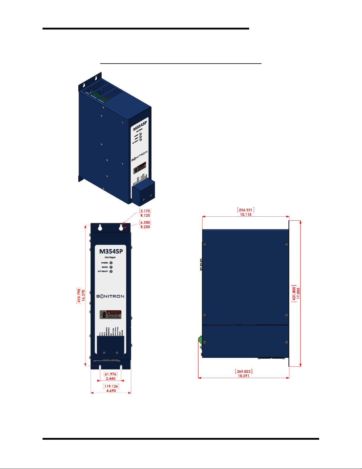
6.6. DIMENSIONS AND MECHANICAL DRAWINGS
Figure 6-1: M3545P M4 Chassis Dimensional Outline
Page 30

M3545P
30
This page intentionally left blank
Page 31

User’s Manual
31
7. APPENDIX
7.1. APPLICATION NOTES
7.1.1. SIZING THE M3545P
The M3545P unit is sized for the amount of DC bus current, I
DC,
which it must
carry. To obtain the amount of DC bus current needed during deceleration;
the load and motor inertias, desired change in RPM, and required stopping
time must be known. With these application variables, the following
calculations can be made to size the M3545P. Use the equation below to
establish the torque required to decelerate or stop a rotating object.
The equations below are valid for using the M3545P for three phase power.
CALCULATE MOTOR TORQUE
Calculating the motor torque
Where
T is torque measured in lb·ft.
1.0 lb·ft = 1.355818 Nm
WK
2
is the total inertial load to be decelerated (lb·ft2).
1.0 lb·ft2 = 0.04214011 kg·m2
ΔN is the change in rotational speed (rpm).
308 is a constant
ton is time required to decelerate the load (s).
CALCULATE MOTOR POWER
Calculating the power (HP) regenerated:
Where
N
max
is the maximum rotational speed (rpm).
The constant 5252 has units of lb·ft/min/radian.
CALCULATE DC BUS CURRENT
Calculating the regenerated DC bus current, IDC.
The DC bus current, IDC, is approximated for the following AC line voltages:
For 230 V
AC
systems:
For 380 V
AC
systems:
For 460 V
AC
systems:
For 575 V
AC
systems:
Once I
DC
is known, you will be able to appropriately size the line regen
based upon its current rating.
Page 32

M3545P
32
7.1.2. CALCULATING ENERGY SAVINGS
The M3545P directs energy from the mechanical load to the power
distribution line, where the energy is available to other connected loads.
These units provide system energy savings over dynamic braking kits,
because the net energy required from the distribution system is reduced by
the regenerated energy. Additional savings also come from the lack of a need
to provide air conditioning with a dynamic braking kit and from reduced time
spent stopping loads.
To calculate the savings, the regeneration duty cycle, the length of operation,
the regenerated HP, and the cost of energy must be known. With these
application variables, the following calculation may be made to determine the
cost savings:
CALCULATE SAVINGS PER YEAR
Calculating total savings per year in dollars:
Where
S is Savings per year.
C is the cost in dollars per kW.
P is the regenerated power.
D is the number of days the system is operated.
H is the number of hours per day the system is operated.
ton is the number of seconds per cycle T power is regenerated.
t
cycle
is the total time to complete a cycle.
SAVING EXAMPLE
Assume the following values for this example:
C = $0.11 per kW
P = 20HP peak, 15HP average during deceleration
D = 365 days
H = 10 hours per day
t
on
= 5 seconds regen is on
t
cycle
= 15 seconds
Savings:
Page 33

User’s Manual
33
NOTES
Page 34

M3545P
34
Page 35

Page 36

D_M3545P_CMAN_vall_00c 01/08/2019
521 Fairground Court ● Nashville, TN 37211 ● USA
 Loading...