

Page 1

Model M3345
Line Regeneration Module for AC Drives
Customer Reference Manual
Page 2
Bonitron, Inc.
Bonitron, Inc.
An Industry Leader in AC Drive Systems and Industrial Electronics
OUR COMPANY
Bonitron is an international supplier of power controls designed to improve the performance and
reliability of electronic systems and variable frequency drives. Located in Nashville, Tennessee,
and founded in 1962, Bonitron has gained a reputation for designing and manufacturing
products with the highest possible degree of quality and reliability.
Bonitron has all the necessary resources in-house for complete electronic product development
and manufacturing. Engineering facilities include a CAD lab for circuit board design and
engineering labs for prototype testing and evaluation. Production facilities include production
areas for circuit board assembly, a machine tool and sheet metal shop for chassis fabrication,
and a systems assembly and checkout area. With these assets, Bonitron is positioned to be a
leader into the future while maintaining first class support for their current customer base.
Worldwide sales of equipment are generated mainly by reputation and referrals. Our customer
base includes all of the major drive manufacturers, their distributors, OEMs, end users, and
many other satisfied companies. Equipment is installed throughout the United States as well as
in Canada, Mexico, Costa Rica, Argentina, Brazil, Chile, Venezuela, Northern Ireland, the
Netherlands, Spain, Hungary, Israel, Turkey, China, India, Indonesia, Singapore, Taiwan, and
the Philippines.
ii
Page 3

Bonitron, Inc.
TALENTED PEOPLE MAKING GREAT PRODUCTS
The engineering team at Bonitron has the background and expertise needed to design, develop,
and manufacture the quality industrial systems demanded by today’s client. A strong academic
background supported by continuing education is complemented by many years of hands-on
field experience. Expertise encompasses a broad range of applications and engineering
solutions such as modern power conversion design techniques and microprocessor-based
controls. This insures a solution tailored to the specific needs of the client.
A clear advantage that Bonitron has over many competitors is combined on-site engineering
labs and manufacturing facilities. This allows the engineering team to have immediate access
to and response from testing and manufacturing. This not only saves time during prototype
development, but also is essential to providing only the best quality products.
AC DRIVE OPTIONS
In 1975, Bonitron began working with the AC inverter drive specialists at synthetic fiber plants to
develop speed control systems that could be interfaced to their plant process computers. Since
that time, Bonitron has developed AC drive option modules that help overcome many of the
problems encountered in applications of modern AC variable frequency drives.
Bonitron’s Ride-Thru module provides protection from AC line voltage sags while the Line
Regen and Resistive Braking modules provide DC Bus regulation for over-voltage due to
regenerated voltage.
Bonitron AC drive modules are available to provide Undervoltage, Overvoltage, Line Side, Load
Side, Maintenance, Power Quality, and Green / Sustainability solutions. These products are
compatible with the drives of all major manufacturers and have become the standard in many
industries including semiconductor, oil, and fiber.
WORLD CLASS PRODUCTS
Bonitron has developed over 3000 different modules and systems. Bonitron is willing and able
to meet the unique specifications the client may request.
Some Bonitron products include:
Power Dip Ride-Thru Modules
Power Outage Ride-Thru Modules
Line Regen Modules
Resistive Braking Modules
Modular High Speed Precision AC Inverter Systems
Inverter Upgrade Modules
Multi-motor, Multi-phase Current Sensors
Battery Production Charging Systems
Data Acquisition Systems
Process Controllers
Temperature Control Systems
RMS True Reading Digital Voltmeters, Ammeters, and Frequency Meters
iii
Page 4

M3345
1. INTRODUCTION ..........................................................................................................................1
1.1. Who should use ............................................................................................................................ 1
1.2. Purpose and Scope ........................................................................................................................ 1
1.3. Manual version and change record ............................................................................................... 1
Figure 1-1: Typical M3345 Unit in the “S” and “C” Chassis ................................................................... 1
2. PRODUCT DESCRIPTION .............................................................................................................2
2.1. Related Docs ................................................................................................................................. 2
2.2. Part Number Breakdown .............................................................................................................. 2
Figure 2-1: Example of M3345 Part Number Breakdown ....................................................................... 2
Table 2-1: Voltage Rating ........................................................................................................................ 3
Table 2-2: Current Ratings ....................................................................................................................... 3
Table 2-3: Chassis Styles ......................................................................................................................... 3
2.3. General Specifications Chart ........................................................................................................ 4
Table 2-4: General Specifications ............................................................................................................ 4
2.4. General Precautions and Safety Warnings ................................................................................... 5
3. INSTALLATION INSTRUCTIONS ..................................................................................................7
3.1. Environment ................................................................................................................................. 7
3.2. Unpacking ..................................................................................................................................... 7
3.3. Mounting ...................................................................................................................................... 7
Figure 3-1: M3345 Mounting Orientation ................................................................................................ 8
3.4. Wiring and Customer Connections ............................................................................................... 9
3.4.1. Power Wiring ........................................................................................................................ 9
Table 3-1: Power Terminal Specifications – 10 to 45 Amp Chassis ...................................................... 10
Table 3-2: Power Terminal Specifications – 60&90 Amp Chassis ........................................................ 10
Table 3-3: Power Terminal Specifications – 120 Amp Chassis ............................................................. 10
3.4.2. I/O Wiring ........................................................................................................................... 10
Table 3-4: I/O Terminal Specifications – S Chassis............................................................................... 10
Table 3-5: I/O Terminal Specifications – B and X Chassis .................................................................. 11
Table 3-6: I/O Terminal Specifications – Y, C, W, Z, and V Chassis.................................................... 11
Figure 3-2: “S” Chassis Connections ..................................................................................................... 11
Figure 3-3: “W” Chassis Connections .................................................................................................... 11
Figure 3-4: “V” Chassis Connections .................................................................................................... 12
Figure 3-5: “X” and “B” Chassis Connections ....................................................................................... 12
Figure 3-6: 60&90 Amp “C” Chx Conn. ........................................................................................... 12
Figure 3-7: 120 Amp “C” Chx Conn. ..................................................................................................... 12
Figure 3-8: “Y” and “Z” Chassis Connections ....................................................................................... 12
3.5. Typical Configurations ............................................................................................................... 12
Figure 3-9: M3345 10-120 Amp Single Drive / Regen Field Wiring Diagram...................................... 13
Figure 3-10: M3345 Multiple Drives/ Regens Field Wiring Diagram ................................................... 14
Figure 3-11: M3345 Master Slave I/O Connection Diagram ................................................................. 15
Figure 3-12: Control Board & Jumper Configuration ............................................................................ 16
4. OPERATION ..............................................................................................................................17
4.1. Functional Description ............................................................................................................... 17
4.2. Features ....................................................................................................................................... 17
4.2.1. Fusing .................................................................................................................................. 17
4.2.2. Internal Line Filtering ......................................................................................................... 17
4.2.3. Indicators ............................................................................................................................. 18
4.2.4. Status Contact ..................................................................................................................... 18
4.2.5. I/O For Paralleling Regens .................................................................................................. 18
iv
Page 5

Table of Contents
4.3. Startup ......................................................................................................................................... 19
4.3.1. Pre-power Checks ............................................................................................................... 19
4.3.2. Startup Procedure and Checks ............................................................................................ 19
4.3.3. Cooling Fan ......................................................................................................................... 19
4.4. Operational Adjustments ............................................................................................................ 19
5. MAINTENANCE AND TROUBLESHOOTING ...............................................................................21
5.1. Periodic Testing .......................................................................................................................... 21
5.2. Maintenance Items ...................................................................................................................... 21
5.3. Troubleshooting .......................................................................................................................... 21
5.3.1. POWER lamp is out: ........................................................................................................... 21
5.3.2. RUN light is out .................................................................................................................. 21
5.3.3. Status Contact remains open after a 5 second delay ........................................................... 22
5.3.4. Meter showing excessive current when in standby ( >3% rated current) ........................... 22
5.3.5. Drive trips on DC Bus Overvoltage .................................................................................... 22
5.3.6. OVERLOAD light is flickering .......................................................................................... 22
5.3.7. CURRENT LIMIT light is on ............................................................................................. 22
5.3.8. Technical Help – before you call ........................................................................................ 23
6. ENGINEERING DATA ................................................................................................................25
6.1. Ratings Charts ............................................................................................................................. 25
Table 6-1: Ratings and Specifications – 230VAC ................................................................................. 25
Table 6-2: Ratings and Specifications – 380VAC ................................................................................. 26
Table 6-3: Ratings and Specifications – 460VAC ................................................................................. 27
6.2. Watt Loss .................................................................................................................................... 28
6.3. Certifications .............................................................................................................................. 28
6.4. Fuse/Circuit Breaker Sizing and Rating ..................................................................................... 28
Table 6-4: Replacement Fuses ............................................................................................................... 28
6.5. Dimensions and Mechanical Drawings ...................................................................................... 29
Figure 6-1: M3345 “S” Chassis Dimensional Outline ........................................................................... 29
Figure 6-2: M3345 “W” Chassis Dimensional Outline .......................................................................... 30
Figure 6-3: M3345 “V” Chassis Dimensional Outline ........................................................................... 31
Figure 6-4: M3345 “B” Chassis Dimensional Outline ........................................................................... 32
Figure 6-5: M3345 “B” Chassis with Fan Dimensional Outline ............................................................ 33
Figure 6-6: M3345 “C” Chassis Dimensional Outline ........................................................................... 34
Figure 6-7: M3345 “X” Chassis Dimensional Outline ........................................................................... 35
Figure 6-8: M3345 “X” Chassis with Fan Dimensional Outline ............................................................ 36
Figure 6-9: M3345 “Y” Chassis Dimensional Outline ........................................................................... 37
Figure 6-10: M3345 “Z” Chassis Dimensional Outline ......................................................................... 38
6.6. Block Diagram ............................................................................................................................ 39
Figure 6-11: Line Regen Functional Block Diagram ............................................................................. 39
7. APPENDIX .................................................................................................................................41
7.1. Application Notes ....................................................................................................................... 41
7.1.1. Sizing the Line Regeneration Control ................................................................................. 41
7.1.2. Calculating Energy Savings ................................................................................................ 41
7.1.3. Savings Example ................................................................................................................. 42
v
Page 6

M3345
This page intentionally left blank.
vi
Page 7
User’s Manual
1. INTRODUCTION
1.1. WHO SHOULD USE
This manual is intended for use by anyone who is responsible for integrating,
installing, maintaining, troubleshooting, or using this equipment with any AC Drive
System.
Please keep this manual for future reference.
1.2. PURPOSE AND SCOPE
This manual is a user’s guide for the Model M3345 Line Regen Control modules. It
provides you with the necessary information to successfully install and use the
M3345 modules in your application.
In the event of any conflict between this document and any publication and/or
documentation related to the application, the latter shall have precedence.
1.3. MANUAL VERSION AND CHANGE RECORD
Ratings Charts are updated in Rev 05a and Rev 05b.
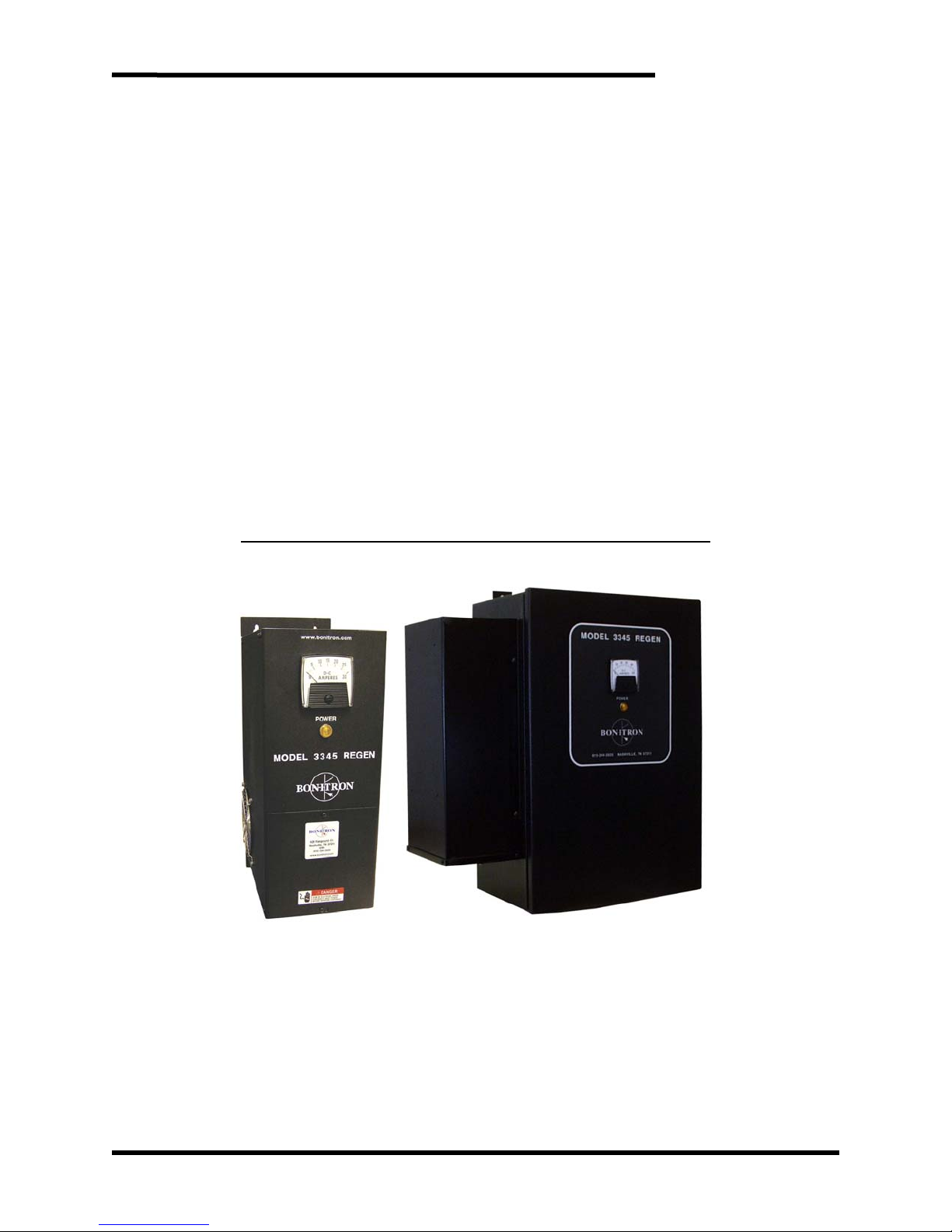
Figure 1-1: Typical M3345 Unit in the “S” and “C” Chassis
1
Page 8
M3345
2. PRODUCT DESCRIPTION
The need for regenerated voltage control occurs when the frequency of an AC motor is
greater than the frequency of the AC line or variable frequency drive providing power to
the motor. In this case, the motor acts as a generator. The energy generated by a
motor must be dissipated or returned to the power source. If this energy is not
controlled, the motor may run with high voltage, the energy may be dissipated as heat in
the motor, or the drive may trip on an overvoltage condition.
Bonitron’s Model 3345 Regen Module is used for regeneration control of any AC drive
system that uses a fixed bus system, such as the bus system used on AC PWM drives.
The Regen module can pass the regenerated energy from the DC bus of the drive to the
AC line. This provides for regulation of the DC bus and prevents the drives from tripping
on overvoltage.
When a dynamic braking resistor is used with a PWM drive, the regenerated energy is
dissipated as heat and energy is wasted. When the Model 3345 Regen Module is used,
the regenerated energy is returned to the input AC line with near unity power factor.
Substantial energy savings may occur as the regenerated energy can be used to power
other equipment.
2.1. RELATED DOCS
COMMON BUS SHARING AND ISOLATION DIODES
• For applications with multiple drives
• M3345D, M3345CBM
BRAKING TRANSISTORS
• For redundant operation with M3345 or for applications above 270A
• M3452, M3575T
BRAKING RESISTORS
• Used with Braking Transistors
• M3575R, M37775R
2.2. PART NUMBER BREAKDOWN
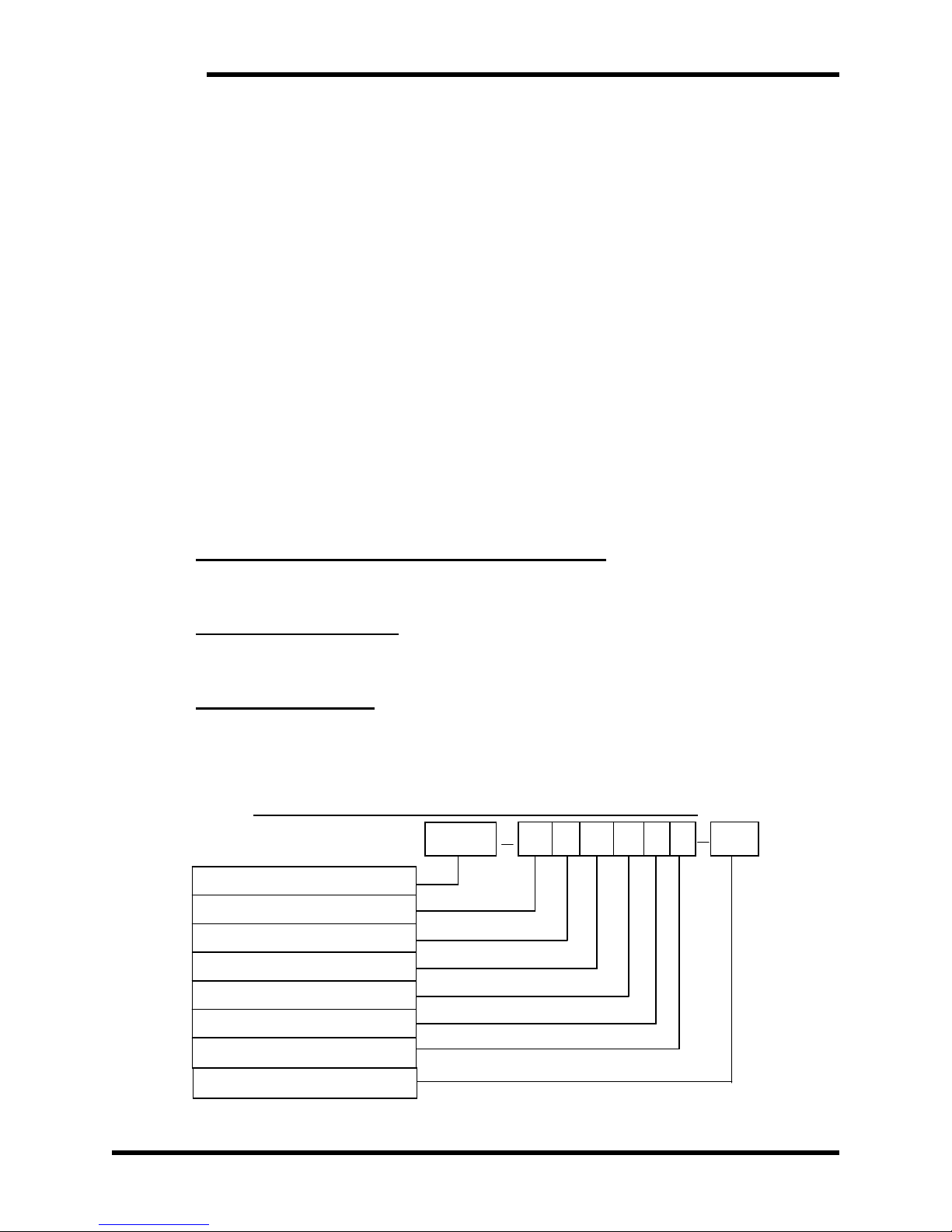
Figure 2-1: Example of M3345 Part Number Breakdown
M3345
BASE MODEL NUMBER
VOLTAGE RATING
CURRENT RATING
CHASSIS STYLE
CURRENT METER
4 1 S M 0 F
50HZ
COOLING FAN
SPECIAL OPTIONS
FREQUENCY
2
Page 9
User’s Manual
BASE MODEL NUMBER
The Base Model Number for all Line Regen Controllers is M3345.
VOLTAGE RATING
A 1 digit code represents the 3∅ AC line input voltage to the Regen module. The
voltage rating must be selected for the system voltage that will be applied.
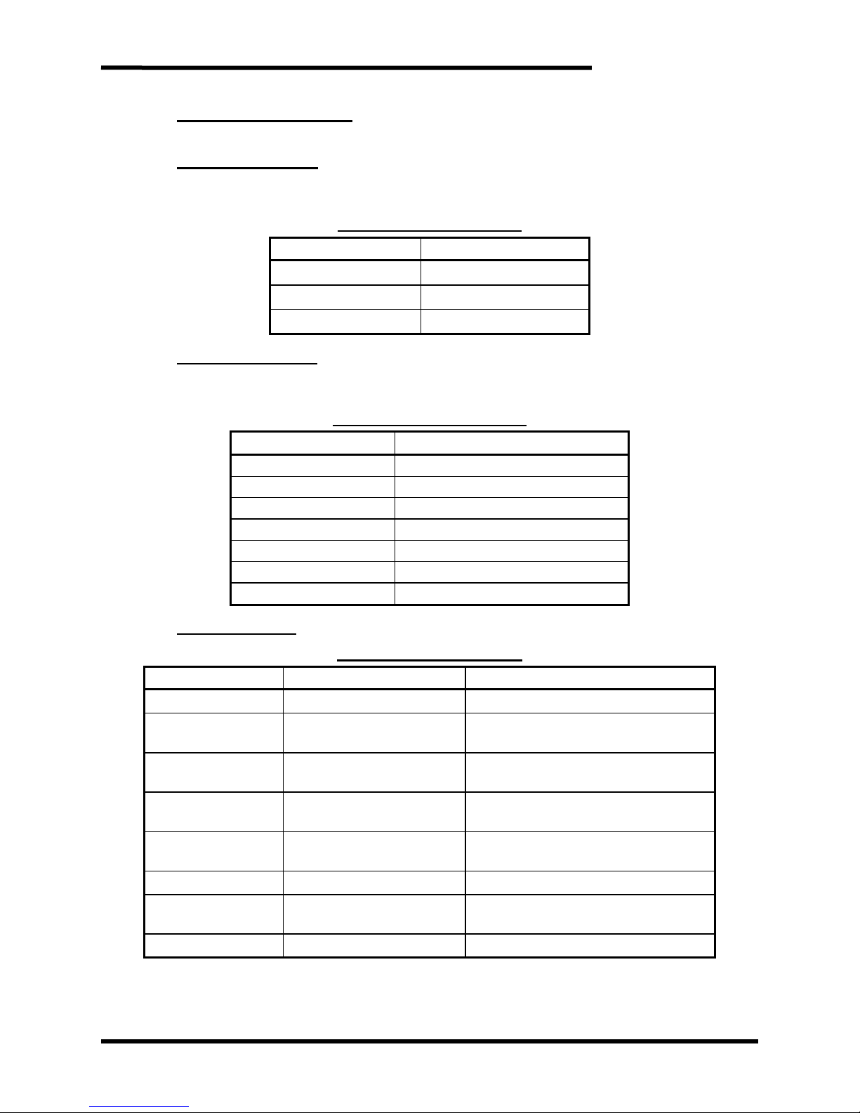
Table 2-1: Voltage Rating
RATING CODE VOLTAGE
2 230 - 240VAC
3 380 - 415VAC
4 460 - 480VAC
CURRENT RATING
A 1-digit code represents the maximum DC current which the Regen module can
dissipate. This is an absolute maximum rating.
Table 2-2: Current Ratings
RATING CODE CURRENT
0 10 Amps
1 20 Amps
2 30 Amps
4 45 Amps
A 60 Amps
5 90 Amps
6 120 Amps
CHASSIS STYLE
Table 2-3: Chassis Styles
CHASSIS CODE DESCRIPTION SIZE (H X W X D)
S (10-45 Amps) Type-1 enclosure 17.75” x 6.00” x 11.00”
B (10-45 Amps)
X (10-45 Amps)
Y (30-90 Amps)
C (30-120 Amps)
W (60-90 Amps) Type-1 enclosure 20.00” x 10.00” x 10.50”
Z (60-120 Amps)
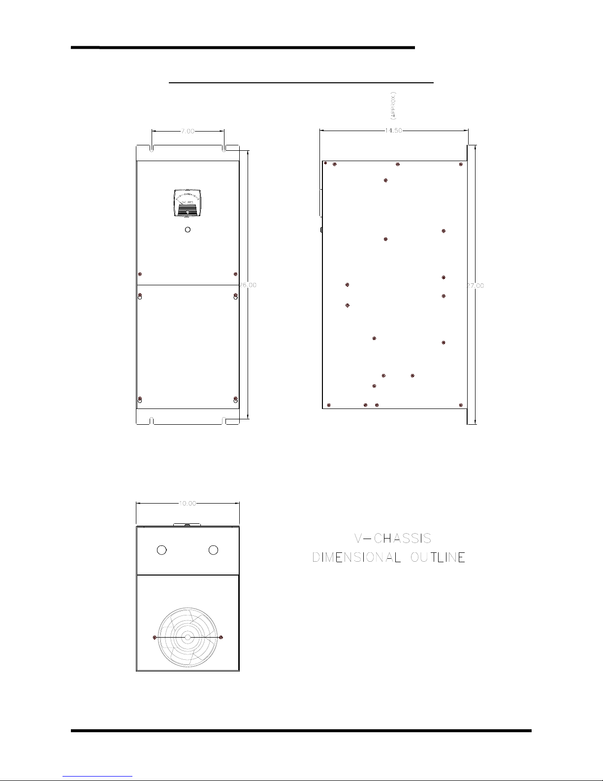
V (120 Amps) Type-1 enclosure 27.00” x 10.00” x 14.50”
Type-13 JIC type wall
mount enclosure
Open chassis, panel
mount backplate
Open chassis, panel
mount backplate
Type-13 JIC type wall
mount enclosure
Open chassis, panel
mount backplate
Type-1 may also be known as ‘bookshelf’.
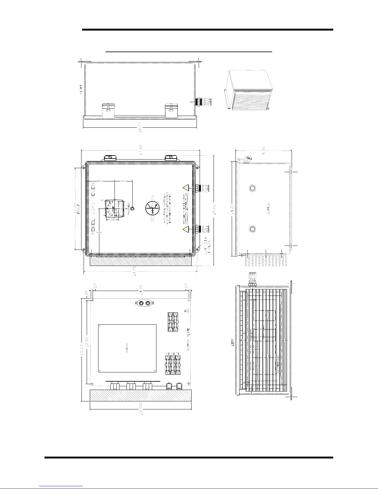
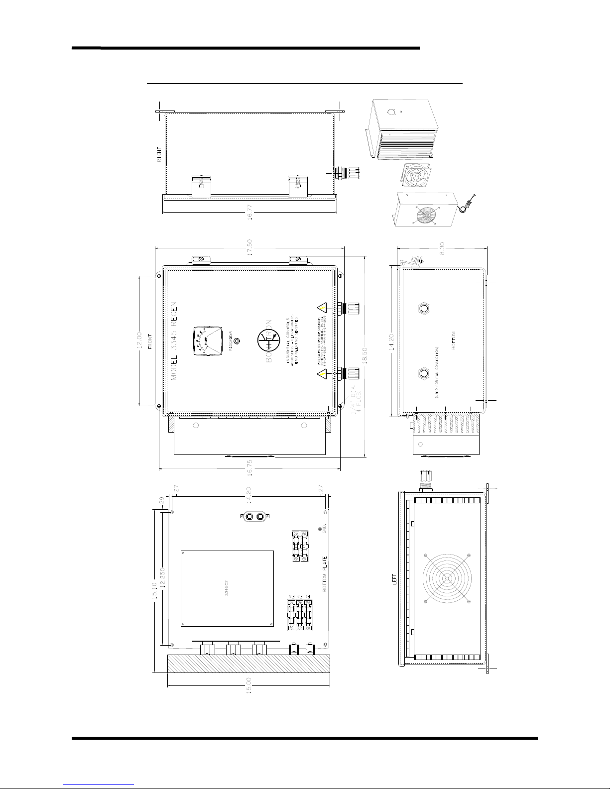
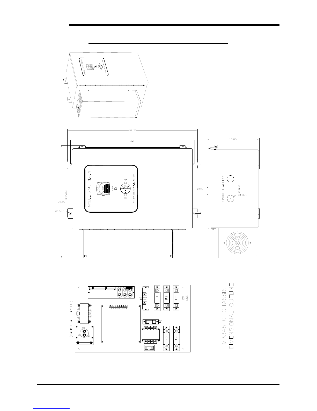
See Section 6.5 for chassis mounting and dimensional outlines.
without fan: 17.50” x 16.25” x 8.25”
with fan: 17.50” x 18.50” x 8.25”
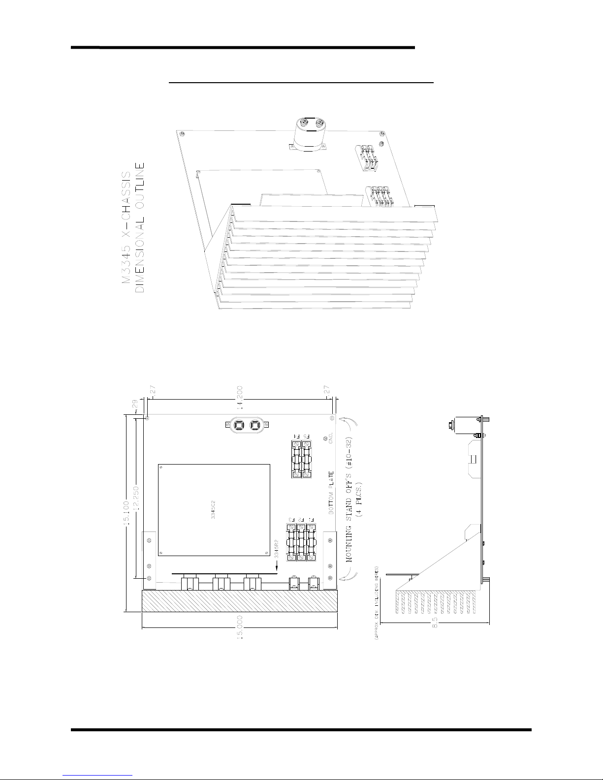
without fan: 15.00” x 15.10” x 8.50”
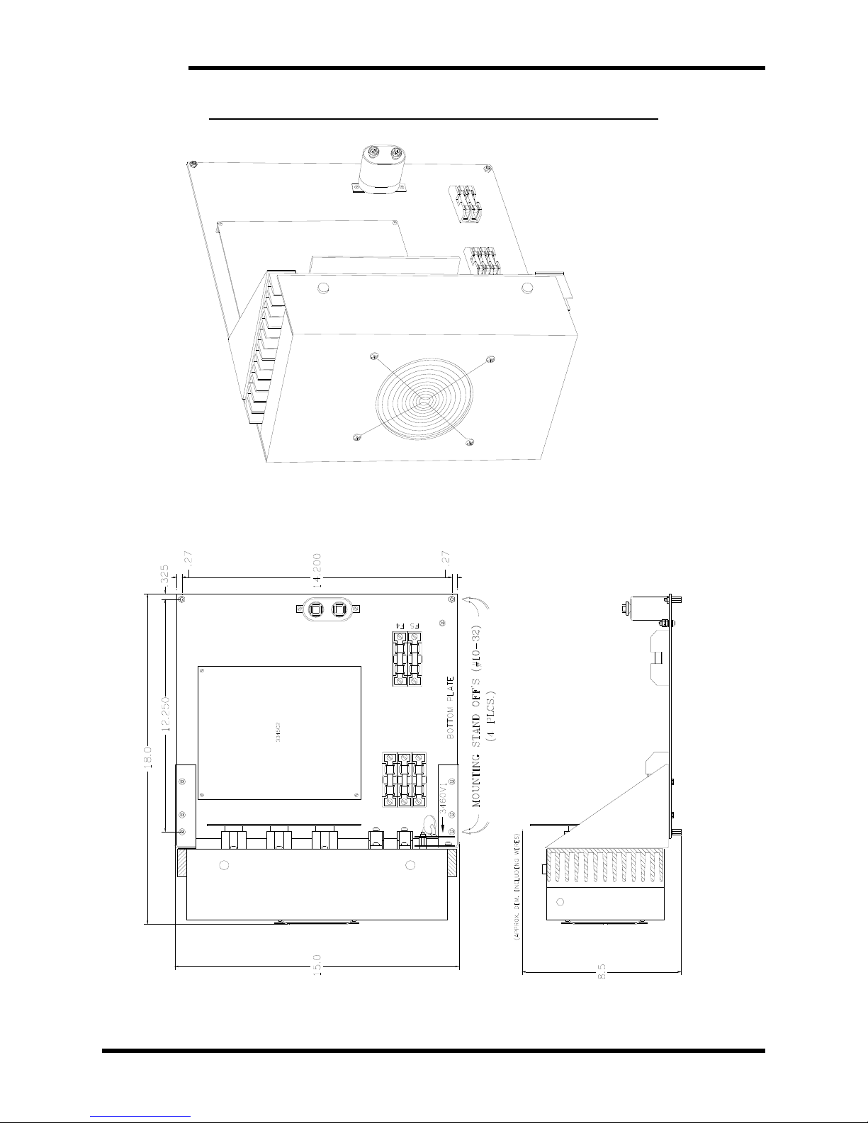
with fan: 15.00” x 18.00” x 8.50”
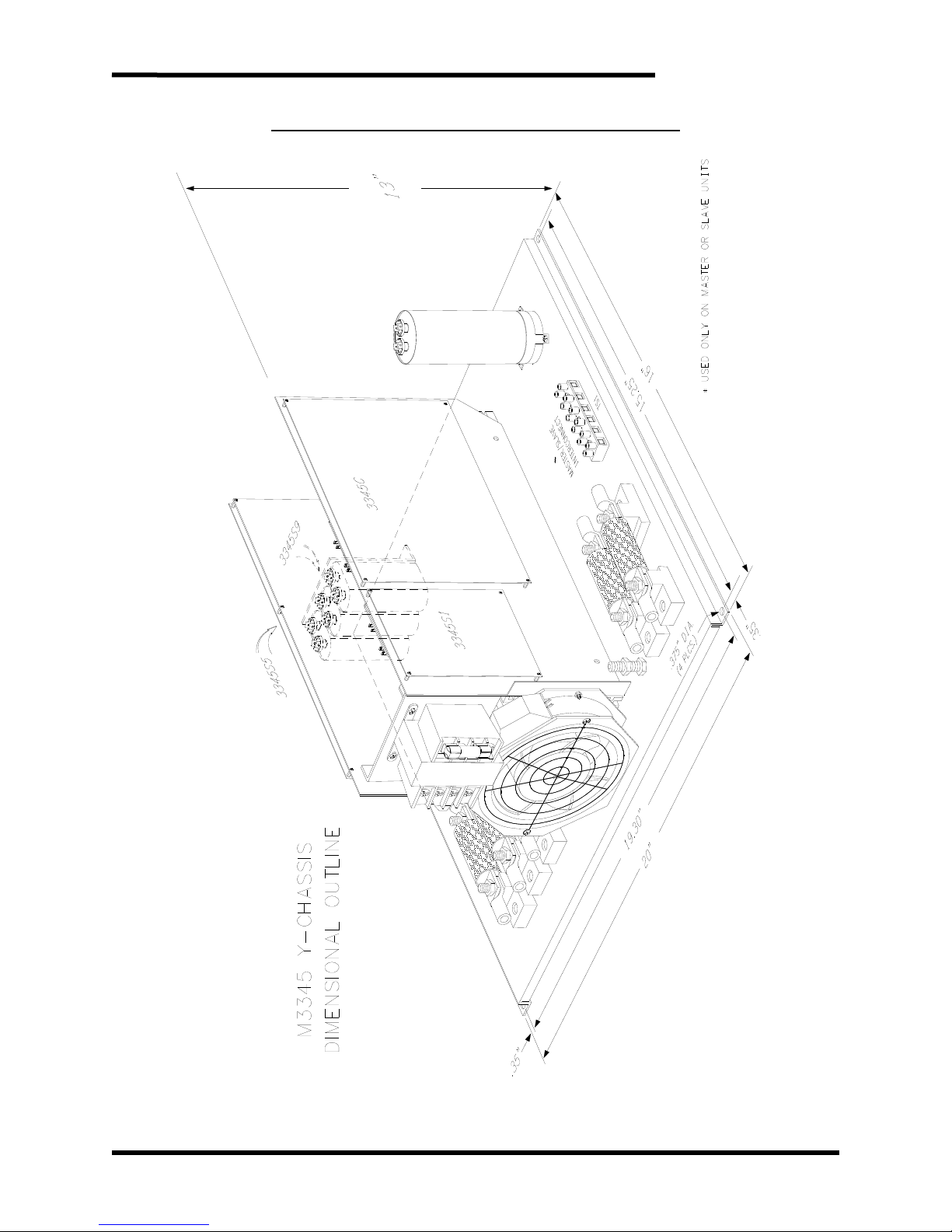
16.00” x 20.00” x 11.00”
26.50” x 23.00” x 10.50”
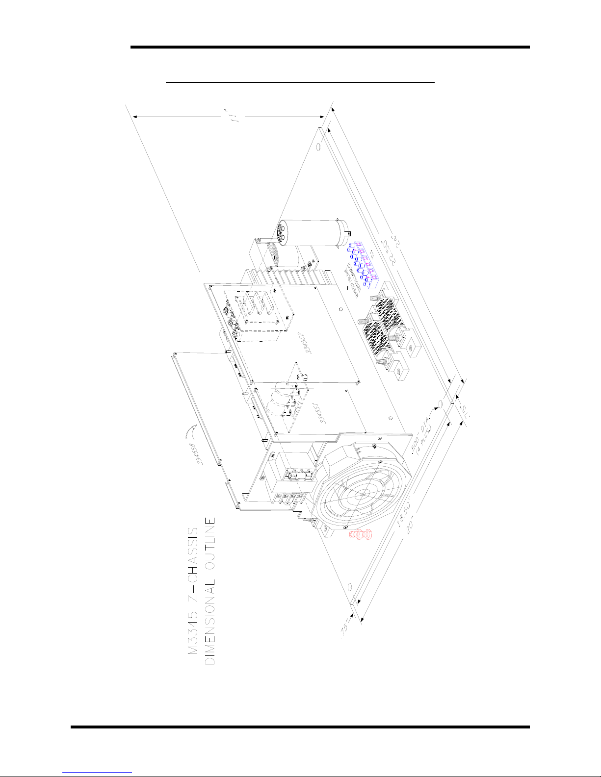
24.00” x 20.00” x 11.00”
3
Page 10
M3345
CURRENT METER
An “M” in this position indicates the inclusion of a DC Regen current meter with the
Regen module. A “0” in this position will omit the meter. A meter is provided as a
standard part of all Type-13 JIC chassis modules and Type-1 chassis modules and is
optional for all open-chassis modules.
COOLING FAN
An “F” in this position indicates the inclusion of a cooling fan with the Regen module.
A “0” in this position will omit the cooling fan. A cooling fan is provided as a standard
part of all chassis types except for the “B” and “X” chassis modules; however the
cooling fan is an available option for the “B” and “X” chassis modules. Please note
that a Regen module’s rating is somewhat dependant on the use of a cooling fan.
Refer to the tables in Section 6 of this manual to determine if a cooling fan is
required for your application.
SPECIAL OPTIONS
ATTENTION!
• A “0” in this position indicates the unit is not Master / Slave selectable.
• An “M” in this position indicates the unit is 60A or higher and is Master / Slave
selectable.
Units with current ratings of 60-90 Amps will support Master/Slave operation.
Units with current ratings of 10-45 Amps, and of 120 Amps will not support
Master/Slave operation.
FREQUENCY
• If the unit is for use on 60Hz systems, omit this position.
• 50Hz in this position indicates the unit is for use on 50Hz systems.
2.3. GENERAL SPECIFICATIONS CHART
Table 2-4: General Specifications
PARAMETER SPECIFICATION
Input AC Line
• Three Phase
• Rated Voltage ±10%
Connections
Power Factor Greater than 90%
Current Limit 100% DC Rating
Operating Temp
Storage Temp
Humidity
Atmosphere Free of corrosive or conductive gas and dust
Status Indicators
I/O Ready
• 50Hz or 60Hz
Drive DC Bus
• 100% of rated DC current
Ground
0 to +40°C
-20 to +65 °C
Below 90%
Non-condensing
Power Light
Run
Current Limit
Overload
Current Meter
4
Page 11
User’s Manual
2.4. GENERAL PRECAUTIONS AND SAFETY WARNINGS
DANGER!
CAUTION!
IGH VOLTAGES MAY BE PRESENT!
• H
• N
EVER ATTEMPT TO OPERATE THIS PRODUCT WITH THE
ACCESS DOORS OR COVERS OPENED
• N
EVER ATTEMPT TO SERVICE THIS PRODUCT WITHOUT
FIRST DISCONNECTING POWER TO AND FROM THE UNIT
!
!
• FAILURE TO HEED THESE WARNINGS MAY
RESULT IN SERIOUS BODILY INJURY OR DEATH!
HIS PRODUCT WILL GENERATE HIGH AMBIENT
• T
TEMPERATURES DURING OPERATION
.
• THIS PRODUCT SHOULD BE INSTALLED ON A NON-
FLAMMABLE SURFACE WITH CLEARANCES OF AT LEAST
TWO INCHES IN ALL DIRECTIONS
.
• ALWAYS ALLOW AMPLE TIME FOR THE UNIT TO COOL
BEFORE ATTEMPTING SERVICE ON THIS PRODUCT
.
• BEFORE ATTEMPTING INSTALLATION OR REMOVAL OF
THIS PRODUCT
RESISTIVE LOAD DOCUMENTATION FOR PERTINENT
SAFETY PRECAUTIONS
, BE SURE TO REVIEW ALL DRIVE AND/OR
.
• INSTALLATION AND/OR REMOVAL OF THIS PRODUCT
SHOULD ONLY BE ACCOMPLISHED BY A QUALIFIED
ELECTRICIAN IN ACCORDANCE WITH
NATIONAL
ELECTRICAL CODE OR EQUIVALENT REGULATIONS.
ANY QUESTIONS AS TO APPLICATION, INSTALLATION OR SERVICE
SAFETY SHOULD BE DIRECTED TO THE EQUIPMENT SUPPLIER.
5
Page 12

M3345
This page intentionally left blank
6
Page 13

User’s Manual
3. INSTALLATION INSTRUCTIONS
Installation and/or removal of this product should only be performed by a
qualified electrician in accordance with National Electrical Code or local
CAUTION!
Proper installation of the M3345 Regen Modules should be accomplished following the
steps outlined below. Be sure to refer to the AC Drive instruction manual as these steps
are performed. Please direct all installation inquiries that may arise during the installation
and start up of this product to the equipment supplier or system integrator.
3.1. ENVIRONMENT
3.2. UNPACKING
codes and regulations.
The module should be installed in an area protected from moisture and falling debris.
Buildup of dust or debris may cause poor performance and possibly a failure.
Operating in a wet environment can pose a shock hazard. The recommended
temperature range for operating this module is 0 to +40
Upon receipt of this product, please verify that the product received matches the
product that was ordered and that there is no obvious physical damage to the unit. If
the wrong product was received or the product is damaged in any way, please
contact the supplier from which the product was purchased.
°C.
3.3. MOUNTING
The installation site for the module should be chosen with several considerations in
mind:
• When mounting Regen units in an enclosure, power dissipation should be taken
into account. Refer to Section 6.2 Watt Loss for details.
• The unit requires a minimum clearance of two (2) inches in all directions around it
when mounted near a non-heat source.
• Unit should not be exposed to falling debris or condensation.
Once the installation site has been selected as outlined above, the unit should be
mounted in place.
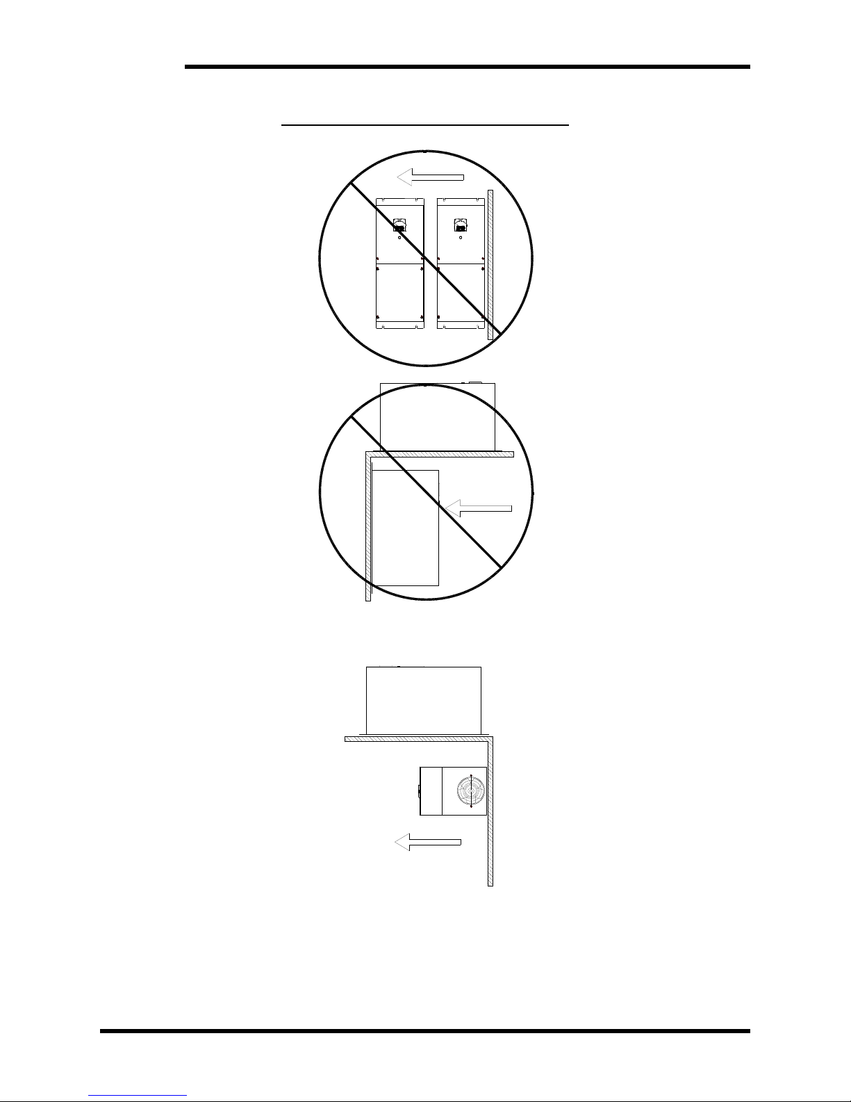
The M3345 must be properly oriented for proper heat flow through the unit. The
M3345 must be mounted with the rear surface of the unit to the mounting surface.
Unit may be mounted vertically or horizontally as shown in Figure 3-1A.
Do Not mount the unit in an upside-down position or on the underside of a mounting
surface as shown in Figure 3-1B.
Do Not mount the unit in a horizontal position with its side parallel to the mounting
surface or floor as shown in Figure 3-1C.
Refer to Table 2-3: Chassis Styles in Section 2.2 of this manual to determine the
chassis for the unit. Mounting dimensions and provisions vary by unit chassis. See
Figure 3-1 for Mounting Orientation information and Section 6.5 for dimensional
drawings.
7
Page 14
M3345
UP
CA
HORIZONTAL TO FLOOR
Figure 3-1: M3345 Mounting Orientation
UP
B
HANGING UNDERSIDE
VERTICAL SURFACE
UP
HORIZONTAL SURFACE
8
Dwg #: 070131 Rev: 20070524
Page 15
User’s Manual
3.4. WIRING AND CUSTOMER CONNECTIONS
Be sure to review all pertinent AC Drive and system documentation as well as the
information listed below before proceeding. Connection points and terminal numbers
of the AC drive will be found in the documentation provided with those units. See
Tables 3-1 thru 3-6 and Figures 3-2 thru 3-11 for connection details.
3.4.1. POWER WIRING
Only qualified electricians should perform and maintain the interconnection
wiring of this product. All wiring should be in accordance with local codes.
WARNING!
Where possible, minimize the wire length between the Regen and the
Drive. The wire length should not exceed 10’.
Avoid routing and bundling the Regen AC/DC wire with the Drive AC
PWM motor output wiring.
3.4.1.1. 3 PHASE AC INPUT
The AC input should be connected to a 3-phase source following the
typical guidelines used when sizing for an inverter. This will insure
sufficient source impedance to return power to the grid. Do not install
chokes or reactors between the regen and the power source. If the AC
drive requires a line reactor, the Regen should be connected to the
utility grid side.
If an isolation transformer is to be used, the regen AC input MUST be
connected to the same point as the drive AC input.
Do not connect to a generator unless minimum load at any time
exceeds the peak expected regen power.
The regen units are not phase sensitive.
Insure that the frequency of the unit is correct when ordered, and only
use 60Hz units on 60Hz systems, 50Hz units on 50Hz systems. This
frequency is specified when the unit is ordered, and cannot be changed
in the field.
Installing 50Hz regen units on 60Hz systems may cause severe damage to
the regen unit.
WARNING!
3.4.1.2. DC BUS INPUT
The DC bus input may be connected to the DC bus of an AC drive, the
DC output of a diode sharing unit, or to a common DC bus. If a reactor
or choke are being used in the bus, make sure the actual connection is
Never attach the DC bus input of the M3345 to braking terminals on the AC
drive, commonly marked “BR”. These terminals are intended for use with an
external resistor, and are not directly connected to the bus filter capacitors of
WARNING!
the drive. Damage may occur if these terminals are used.
Please refer to your AC drive manual or AC drive Technical Support
department for assistance with this connection.
in parallel with filter capacitors of the drive/inverter.
9
Page 16
M3345
A
A
3.4.1.3. GROUNDING
Using the ground stud provided, ground the chassis in accordance with
local codes. Typically the wire gauge will be the same as is used to
ground the attached drive.
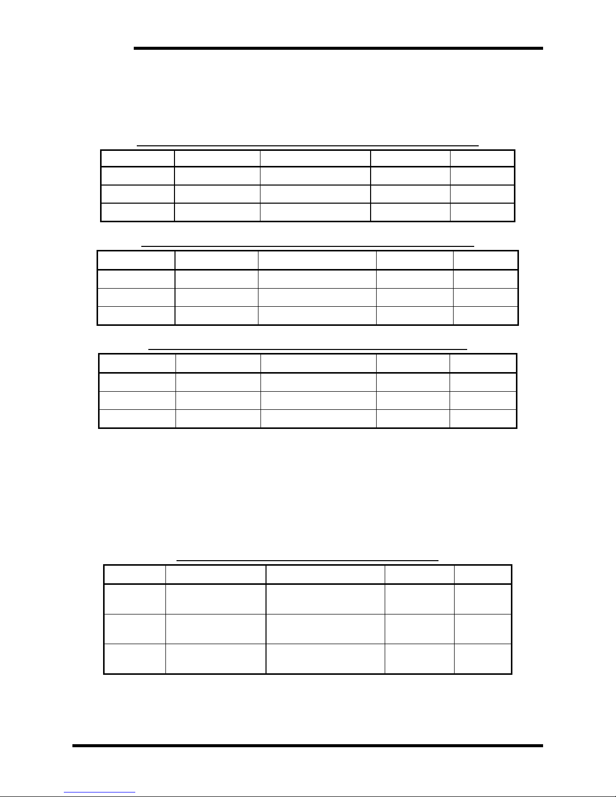
Table 3-1: Power Terminal Specifications – 10 to 45 Amp Chassis
TERMINALS FUNCTION ELECTRICAL RATINGS WIRE SIZE TORQUE
L1, L2, L3 Power Input 45A 230/460VAC #10-32 screw 20 in-lbs
+ ─ DC Bus Input 45A 750VDC #10-32 screw 20 in-lbs
GND Chassis Ground #10-32 screw 20 in-lbs
Table 3-2: Power Terminal Specifications – 60&90 Amp Chassis
TERMINALS FUNCTION ELECTRICAL R
L1, L2, L3 Power Input 90A 230/460VAC 5/16” stud 100 in-lbs
+ ─ DC Bus Input 90A 750VDC 5/16” stud 100 in-lbs
GND Chassis Ground 5/16” stud 100 in-lbs
Table 3-3: Power Terminal Specifications – 120 Amp Chassis
TERMINALS FUNCTION ELECTRICAL R
L1, L2, L3 Power Input 120A 230/460VAC 3/8” stud 182 in-lbs
+ - DC Bus Input 120A 750VDC 3/8” stud 182 in-lbs
GND Chassis Ground 5/16” stud 100 in-lbs
TINGS WIRE SIZE TORQUE
TINGS WIRE SIZE TORQUE
3.4.2. I/O WIRING
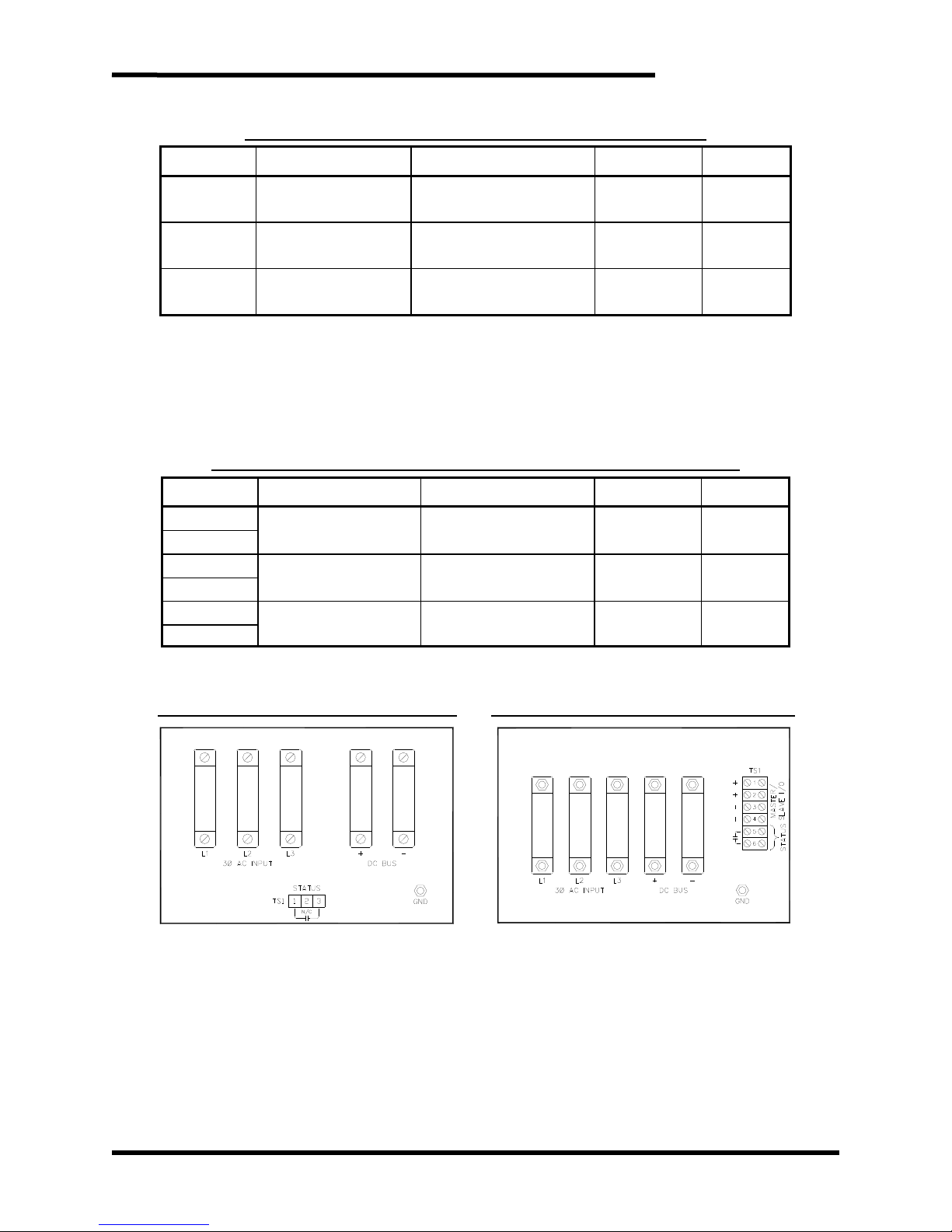
M3345 Line Regens come with a status contact. See Table 3-6 for
Master/Slave I/O terminals.
3.4.2.1. STATUS CONTACT
This is an isolated normally open contact. Contact will energize closed
upon ready condition of unit. Contact is rated for 120V AC/DC @ 2
amps. See Section 4.2.4 for more information.
Table 3-4: I/O Terminal Specifications – S Chassis
TERMINAL FUNCTION ELECTRICAL RATINGS WIRE SIZE TORQUE
TS1-1
TS1-2
TS1-3
Ready Contact
Common
Ready Contact
No Connection
Ready Contact
N.O.
2A - 120V resistive 28-16 AWG 2 in-lbs
2A – 120V resistive 28-16 AWG 2 in-lbs
10
Page 17
User’s Manual
A
Table 3-5: I/O Terminal Specifications – B and X Chassis
TERMINAL FUNCTION ELECTRICAL RATINGS WIRE SIZE TORQUE
TB4-1
TB4-2
TB4-3
Ready Contact
N.C.
Ready Contact
N.O.
Ready Contact
Common
2A - 120V resistive 18-12 AWG 4.5 in-lbs
2A - 120V resistive 18-12 AWG 4.5 in-lbs
2A - 120V resistive 18-12 AWG 4.5 in-lbs
3.4.2.2. MASTER / SLAVE I/O
Units that are rated 60 amps and greater are provided with Master /
Slave I/O terminals for parallel operation. See Figure 3-11 and Section
4.2.5 for more information.
Table 3-6: I/O Terminal Specifications – Y, C, W, Z, and V Chassis
TERMINAL FUNCTION ELECTRICAL R
TS1-1
TS1-2
TS1-3
TS1-4
TS1-5*
TS1-6*
*Not standard in the “Y” chassis.
Reference Table 3-6 when the unit is configured for Master.
TINGS WIRE SIZE TORQUE
Master / Slave + .5A – 250V 18-12 AWG 20 in-lbs
Master / Slave - .5A – 250V 18-12 AWG 20 in-lbs
Ready Contact
NO
2A - 120V resistive 18-12 AWG 20 in-lbs
Figure 3-2: “S” Chassis Connections Figure 3-3: “W” Chassis Connections
Dwg #s: 070133, 070134 Rev: 20080313
11
Page 18
M3345
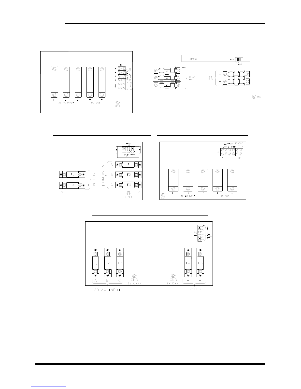
Figure 3-4: “V” Chassis Connections Figure 3-5: “X” and “B” Chassis Connections
Figure 3-8: “Y” and “Z” Chassis Connections
Figure 3-6: 60&90 Amp “C” Chx Conn. Figure 3-7: 120 Amp “C” Chx Conn.
3.5. TYPICAL CONFIGURATIONS
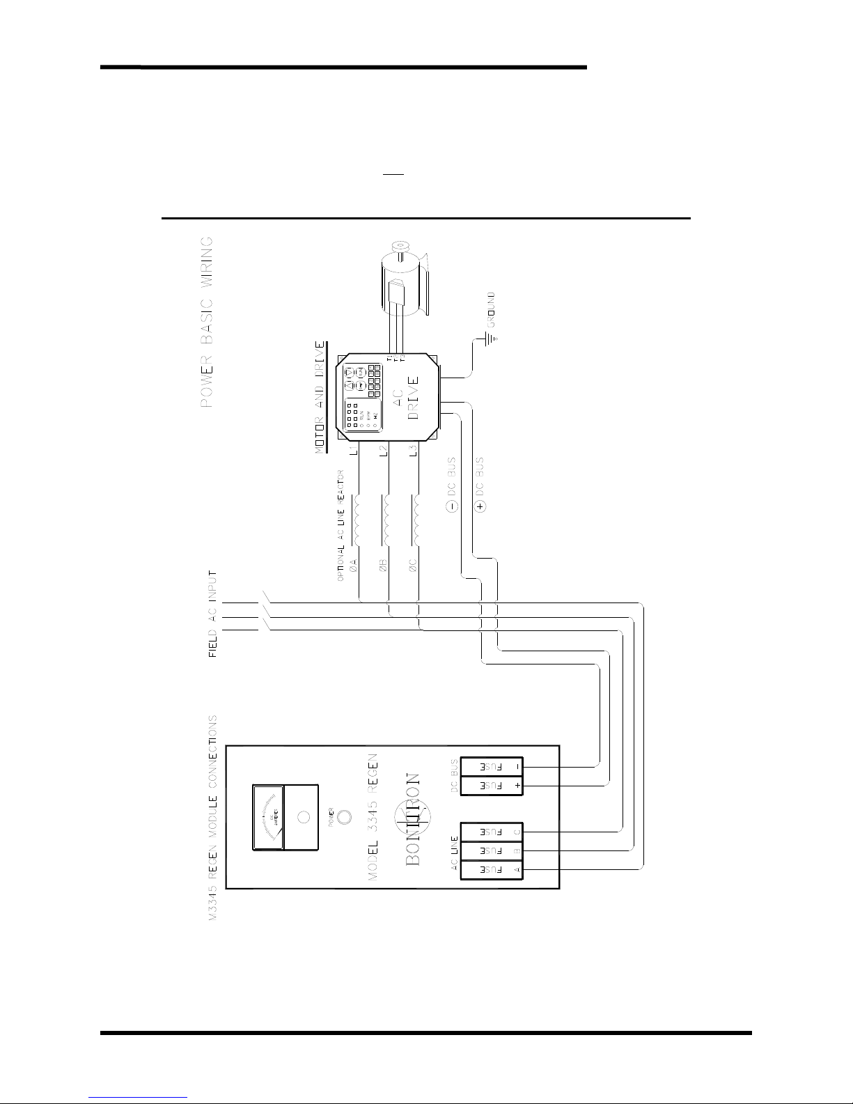
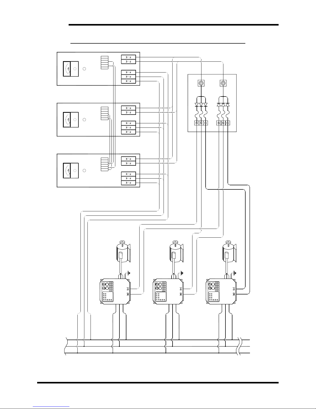
The diagrams shown in Figures 3-9 thru 3-11 illustrate typical connections of the
M3345 Regen units with generic VFDs. There are many other configurations that
may be applied providing a basic connection criterion is maintained such as:
• The AC input should maintain a low impedance path back to the grid.
• No reactors should be connected upstream of the regen unit without
consulting Bonitron for instructions.
12
Dwg #s: 080109, 080110 Rev: 20080219 and 080108, 080130, 070135 Rev 20080313
Page 19
User’s Manual
• The DC input should be connected to a fixed bus whether from a common
bus supply or from the output of a VFD. This should never be connected to a
switching source such as the braking resistor terminals on some drives.
• The DC input should not
without instructions from Bonitron.
be connected to an active SCR front end drive
Figure 3-9: M3345 10-120 Amp Single Drive / Regen Field Wiring Diagram
Dwg #: 010132 Rev: 20070521
13
Page 20
M3345
Figure 3-10: M3345 Multiple Drives/ Regens Field Wiring Diagram
6
5
42136
*SLAVE2*SLAVE1*MASTER
POWER
MODEL 3345 REGEN
5
42136
POWER
MODEL 3345 REGEN
5
3421
POWER
MODEL 3345 REGEN
-
+CBA
DC BUS
AC LINE
NEG.
REGEN
-+
DC BUS
CBA
AC LINE
DC ( - )
DRIVE 1 DC ( - )
-+CBA
AC LINE DC BUS
TYPICAL M3345D
DRIVE 3 DC ( - )
DRIVE 2 DC ( - )
POS.
REGEN
DC ( + )
DRIVE 1 DC ( + )
DRIVE 2 DC ( + )
DRIVE 3 DC ( + )
60A, 90A & 120A ONLY
STATUS I/O
*MASTER/SLAVE &
TYPICAL
RUNSTOP
RUN
MOTOR AND DRIVE
4
0123
RPM
6789
5
HZ
TYPICAL
MOTOR AND DRIVE
T1
T2
T3
GND
1
DC BUS
DRIVE
L3L2L1
T1
T2
T3
4
RUNSTOP
0123
RUN
RPM
6789
5
HZ
2
DRIVE
L1L2L3
GND
DC BUS
TYPICAL
RUNSTOP
RUN
MOTOR AND DRIVE
4
0123
RPM
6789
5
HZ
T1
T2
3
DRIVE
L1L2L3
T3
GND
DC BUS
L3L2L1
AC LINE
14
Dwg #: 950175 Rev: 20070522
Page 21
User’s Manual
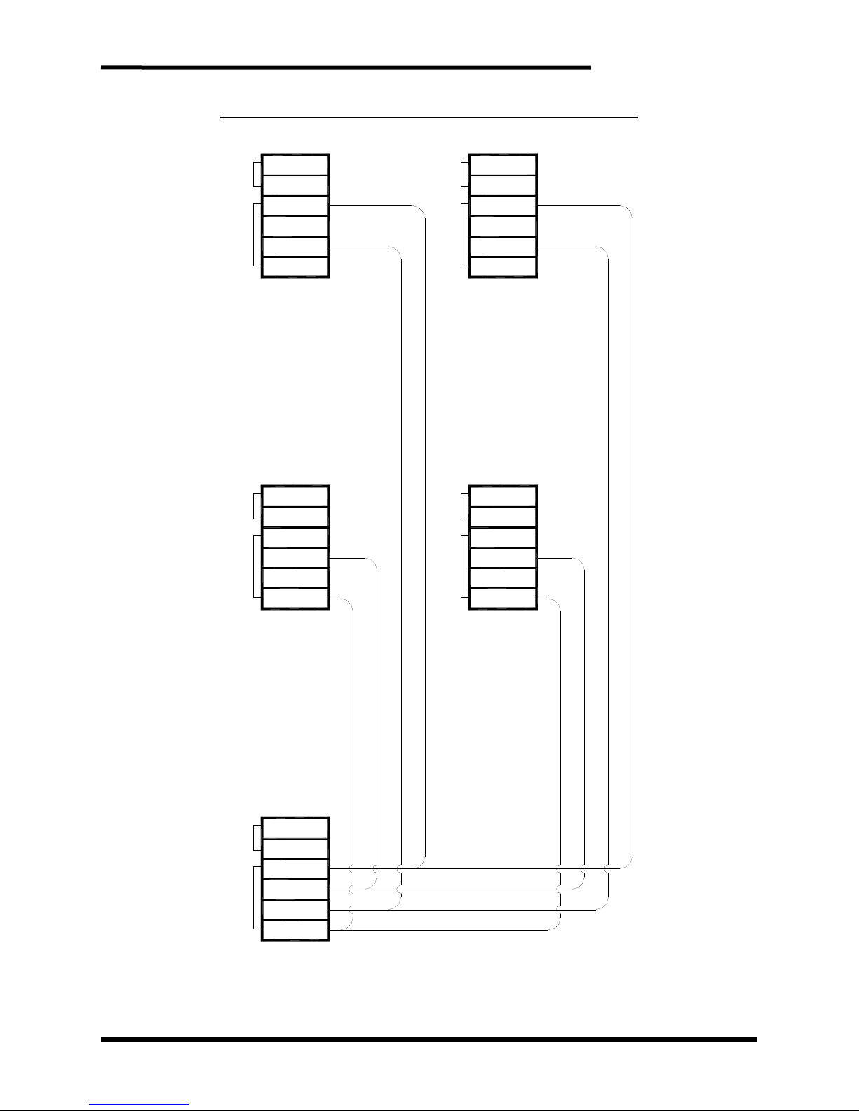
Figure 3-11: M3345 Master Slave I/O Connection Diagram
6
STATUSM-S I/OSTATUSM-S I/OM-S I/O STATUS
5
412
STATUSM-S I/OSTATUSM-S I/O
3
2nd SLAVE
4th SLAVE
6
5
34
12
6
5
3
1st SLAVE
3rd SLAVE
64
5
3
21
12 4
MASTER
6
5
421
3
Dwg #: 070129 Rev: 20070522
15
Page 22
M3345
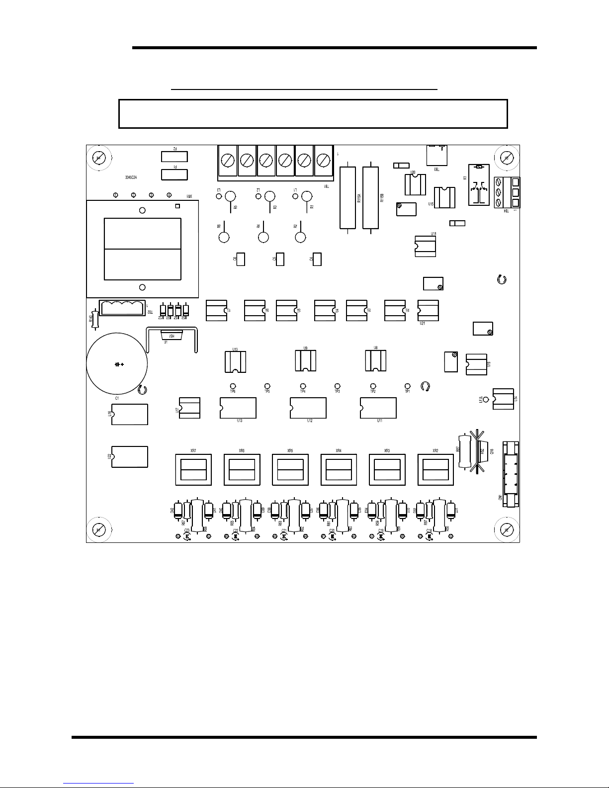
For Single unit or Master operation J1 & J2 must be in the “M” position.
For Slave operation J1 & J2 must be in the “S” position.
J2
S M
R118
S M
J1
LD3
Figure 3-12: Control Board & Jumper Configuration
R159
OVER
LOAD
R89
R82
LD1
I-LIMIT
LD2
RUN/STDBY
16
Page 23

User’s Manual
4. OPERATION
4.1. FUNCTIONAL DESCRIPTION
The M3345 Line Regen enables energy being generated by an over-hauling motor to
be efficiently returned to the power grid. Alternative solutions typically consist of
dissipating the returned energy in a resistor or simply allowing the motor to coast
uncontrolled to a stop.
The M3345 Line Regen establishes a reference from the power source connected to
the 3 phase input. This reference is used to establish the actual rectified DC voltage
which is equal to the DC bus of the AC Drive in standby. The DC reference allows
for conduction back to the AC line with limited rise in DC bus voltage. The reference
is also used to monitor instantaneous changes in the incoming voltage.
Instantaneous changes in voltage greater than 15% can create an over-power
condition for the power semiconductors. The M3345 will go into a shutdown mode
during such events and resume operation upon return of nominal voltage. The
M3345 will also go into the shutdown mode upon loss of any phase of the incoming
power.
The M3345 series of Regen Modules come standard with an internal bus structure
which allows for regeneration from the drive to the AC Line only. Power may be
transferred from the AC drive to the regen; however, the regen will not provide
energy to the AC drive.
4.2. FEATURES
• Fusing
• Internal line filtering
• Current metering
• Power indicator
• Status contact
• I/O for paralleling 60, 90, and 120 Amp units
4.2.1. FUSING
The M3345 Line Regen is provided with fusing for the AC input and the DC
bus input. All fuses are fast semiconductor type and should only be
replaced with original type. Please refer to Table 6-4 in Section 6.4.
4.2.2. INTERNAL LINE FILTERING
The M3345 series Line Regen incorporates internal filtering on the AC line
to remove voltage transients created by the internal transistors. It also adds
additional filtering to noise and harmonics that may be generated outside of
the regen. The internal filtering is not intended for filtering external
harmonics and if there are any known power quality issues extra attention
should be given when startups are performed.
17
Page 24
M3345
4.2.3. INDICATORS
4.2.4. STATUS CONTACT
4.2.3.1. CURRENT METERING
The M3345 Line Regen may come with an ammeter installed. This is an
averaging meter which may not deflect the instantaneous current peaks
which may be present.
4.2.3.2. POWER INDICATOR
The M3345 Line Regen comes standard with a neon power lamp. This
lamp is powered by 2 of the 3 phases feeding the AC input.
This lamp should not be relied upon for determining if voltage is
present! Always check for voltage with dependable measuring
CAUTION!
device before attempting service on unit.
The M3345 Line Regens come equipped with a status contact which may
be integrated into system control I/O. This contact is normally open and
energized closed when ready. The contact will open upon any of the
following events:
Loss of AC voltage
Loss of any phase
Instantaneous change in voltage
Overload condition
Over-temperature
This contact can be used for remote indication of the operation of the unit.
4.2.5. I/O FOR PARALLELING REGENS
The M3345 regeneration units come equipped with Master / Slave
selectable control boards. 60 Amp and 90 Amp units are available for
Master/Slave operations. The “S”, “B”, and “X” chassis units (< 60 Amp) do
not
provide I/O connections for Master / Slave operation. It is imperative
that when paralleling units, one unit be configured as a Master and all
others configured as Slaves. This will allow for up to 4 Slaves and 1 Master
unit to be used in parallel operation. Refer to Figure 3-11 for connection
diagram.
Consult with Bonitron if you plan to configure more than 3 units as
Slaves on the 60 & 90 Amp units.
When a unit is configured as Master, the terminals appear as outputs to the
other units.
When the unit is configured as Slave, the terminals appear as inputs to the
other units.
The signal is a complex waveform that is not reproducible as an analog
input or output. The signal is floating with respect to ground, and could
have a significant potential difference from other references.
Do not attempt to use these signals for any purpose other than
interconnecting Bonitron M3345 units! Damage may occur to the
WARNING!
M3345 as well as to the connected equipment!
18
Page 25
User’s Manual
p
4.3. STARTUP
This section covers basic checks and procedures that should be used when
performing a startup with a M3345 Line Regen.
4.3.1. PRE-POWER CHECKS
Insure that the frequency of the AC power system is the same as the
regen unit.
Insure that the voltage of the AC power system is the same as the
regen unit.
Insure that all connections are tight and that all wiring is of the proper
size and rating for operation.
Verify continuity of all input fuses prior to applying power.
Check for exposed conductors that may lead to inadvertent contact.
Check for any debris, shavings, trimmings, etc that may cause shorts
or obstruct ventilation on unit.
4.3.2. STARTUP PROCEDURE AND CHECKS
After completing Regen pre-checks and recommended checks for
connected equipment you may apply power to the system. The power
indicator on the front panel should illuminate and a small amount of current
may be noticed on the ammeter. If the cover is open, the “RUN” LED
should be illuminated on the 3345C2 control board (see Figure 3-12 for
location). Status contact should be closed after a 2 second delay, which is
an indication that unit is ready for operation. If any of the following
conditions exist, refer to Troubleshooting in Section 5.3.
• Front panel lamp off with power applied.
• Status contact still open after 5 seconds.
• Excessive current flow in standby mode.
If none of the above conditions exist, the Regen Unit is now ready to
operate, and the drive system can be run normally.
4.3.3. COOLING FAN
A heat sink cooling fan may be supplied as part of the Regen unit. The fan
runs continuously when proper system voltage is present at the Regen unit
inputs.
4.4. OPERATIONAL ADJUSTMENTS
Adjustments made outside of the factory settings can cause poor
erformance, reduced system capability, heatsink overheating, or even
component failures. Under severe operating conditions, or if the
settings have been accidentally or intentionally altered, some minor
WARNING!
field adjustment may be required. Consult Bonitron prior to making
any adjustments.
19
Page 26

M3345
This page intentionally left blank
20
Page 27
User’s Manual
5. MAINTENANCE AND TROUBLESHOOTING
Repairs or modifications to this equipment are to be performed by Bonitron approved
personnel only. Any repair or modification to this equipment by personnel not approved
by Bonitron will void any warranty remaining on this unit.
5.1. PERIODIC TESTING
There are no requirements for periodic testing of these units. It may be beneficial to
repeat start-up procedures and checks when performing routine maintenance.
5.2. MAINTENANCE ITEMS
Check the fan periodically for debris, and blow out with an air hose if it has become
obstructed or not running at full capacity. Power should not be applied when
blowing dust and debris out of unit.
5.3. TROUBLESHOOTING
There are no user serviceable parts within the M3345 Regen unit. If you
are still experiencing problems after you have reviewed this whole Section
CAUTION!
The 3345C2 Control Board has 3 LEDs which may be useful in diagnosing problems
with the unit or system. The cover may need to be removed in order to access the
control board. Do not remove any covers with power applied to the unit! Refer
to Figure 3-12 for location of the LEDs on the circuit board. Following is a brief
description of the LEDs and indications:
you may contact Bonitron for additional assistance at (615) 244-2825.
5.3.1. POWER LAMP IS OUT:
• Check AC input voltage at fuses
• Check voltage at output side of fuses
• Check connection to lamp from PCB
5.3.2. RUN LIGHT IS OUT
The RUN LED indicates that the module is enabled and in a ready
condition. This LED is directly related to the status contact at the I/O
terminal. If the RUN LED is ON the status contact should be closed. If the
LED is ON and the status contact does not change there is most likely a
wiring issue. When the power is applied to the module, the RUN LED will
normally come ON after a startup delay of approximately 2 seconds.
Thereafter, the RUN LED should be ON, indicating that the system is ready
to operate. If the RUN LED fails to come ON, one of several faults may be
indicated.
• If the OVERLOAD LED is lit or briefly comes on other than at power-
up, refer to Section 5.3.6.
• If no LEDs are lit, remove power and unplug TB2 and measure
continuity of the purple and purple/tr wires on the connector. This
should be 0 ohms. If connection measures open, the thermostat is
either indicating high temperature or is defective. Switch opens at
175°F and closes at 140°F on all chassis EXCEPT the Y chassis
21
Page 28

M3345
5.3.3. STATUS CONTACT REMAINS OPEN AFTER A 5 SECOND DELAY
5.3.4. METER SHOWING EXCESSIVE CURRENT WHEN IN STANDBY ( >3%
(where the switch opens at 140°F and closes at 110°F). If the unit is
cool, the switch may be defective. Contact Bonitron for service.
• Check the ribbon cable connector CN1 to be securely plugged in.
• If thermostat measures OK, check the continuity of the wires feeding
the 3 phase AC to the control board at TB1. The brown, yellow, and
orange wires should be directly connected to the main input fuses.
• Verify the Dip Threshold as shown in Section 4.4.2.
• Check AC input voltage at fuses to be within +/- 10% of nominal
voltage
• If unit appears to be hot allow a few minutes to cool off
• If status contact does not change try cycling power to the unit
RATED CURRENT
• Measure AC input voltage to be balanced Line to Line
• If more than 5VAC difference, move highest pair to B & C
• Check for harmonics and noise on the AC that may be caused by DC
drives, welders, induction heaters, etc.
• See Section 4.4 about adjustments and/or contact support at Bonitron
)
5.3.5. DRIVE TRIPS ON DC BUS OVERVOLTAGE
• Verify status contact, if open see Section 5.3.3
• Check DC bus voltage at fuses
• Check DC bus polarity at fuse
• Check DC bus fuses
• Ensure unit is not overheated
• Verify proper sizing of regen unit
5.3.6. OVERLOAD LIGHT IS FLICKERING
The normal state for the OVERLOAD LED is OFF. The OVERLOAD LED
may flash for a brief moment on power-up. The OVERLOAD LED indicates
that the system DC bus feedback is substantially greater than the DC bus
reference signal. Under normal operating conditions, this occurs when the
regenerated power from the drive is greater than the capacity of the regen
module. When this occurs, the DC bus rise will cause the regen module to
be temporarily disabled. With the module disabled, the drive DC bus will
continue to rise until the Drive Overvoltage condition causes the drive to trip
OFF. Once the Overvoltage condition ceases to exist, the OVERLOAD
LED will turn OFF and the fault condition will be reset.
Since the drive and regen module have peak rectifier diode modules, a
substantial line transient on the AC power lines can cause an erroneous
OVERLOAD fault even in the standby mode.
5.3.7. CURRENT LIMIT LIGHT IS ON
The normal state for the CURRENT LIMIT LED is OFF. An ON state for the
CURRENT LIMIT LED indicates that there is greater than 100% of the
maximum limit of instantaneous, non-filtered, regenerated current in any 1
of the 3 AC input line feeds. The response of the CURRENT LIMIT LED is
much quicker than the averaging DC bus ammeter frequently supplied with
22
Page 29

User’s Manual
the regen module. The CURRENT LIMIT LED is informative when the
system operation consists of short but high peak currents. An ON state can
indicate the presence of short energy surges which may cause an Overload
condition.
5.3.8. TECHNICAL HELP – BEFORE YOU CALL
If technical help is required, please have the following information available
when calling:
• Model number of unit
• Serial number of unit
• Name of original equipment supplier if available
• Record the Line to Line voltage on all 3 phases
• Record the DC bus voltage immediately after the AC voltage
• Brief description of the application
• Drive and motor hp or kW
• KVA rating of power source
• Source configuration Wye/Delta and grounding
23
Page 30

M3345
This page intentionally left blank
24
Page 31
User’s Manual
6. ENGINEERING DATA
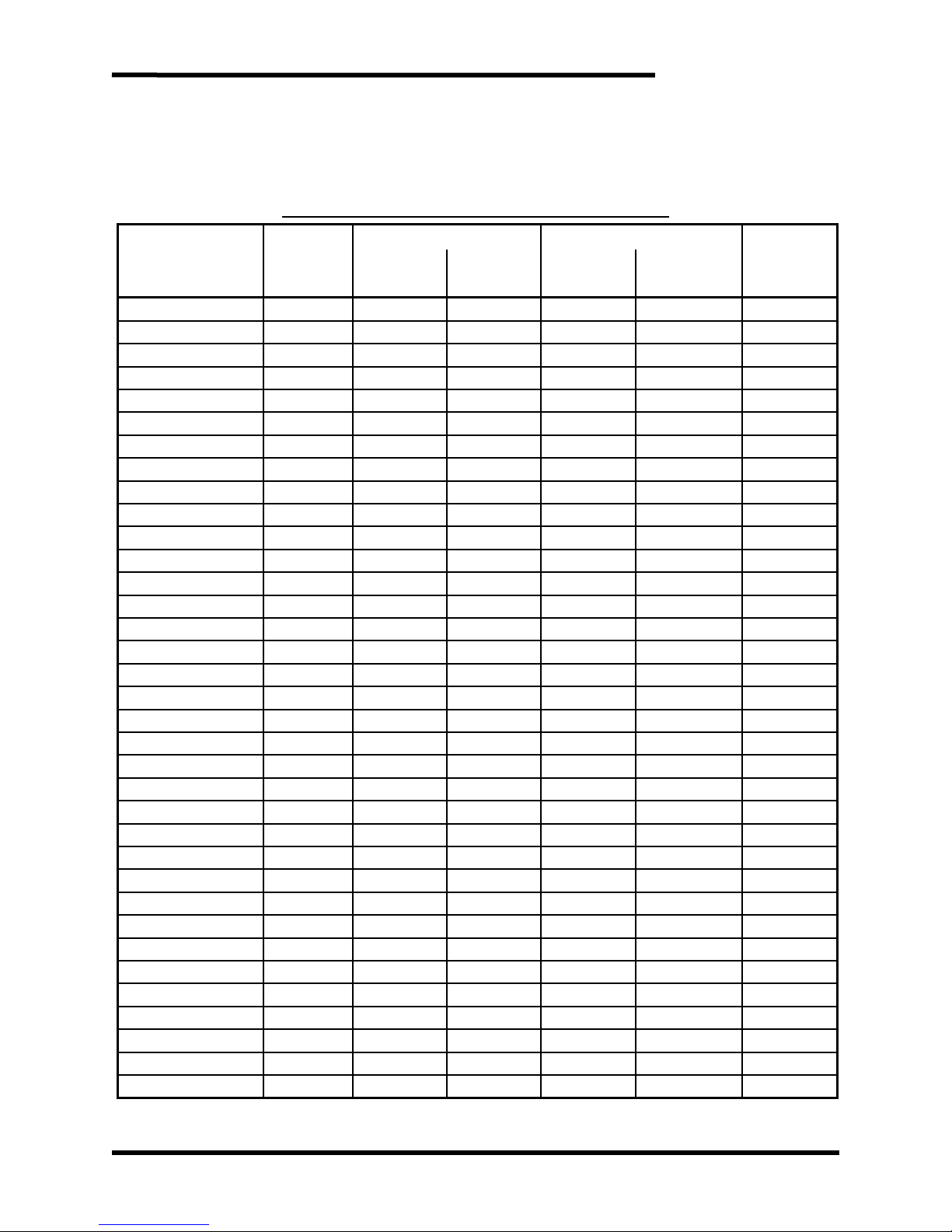
6.1. RATINGS CHARTS
Table 6-1: Ratings and Specifications – 230VAC
ODEL NUMBERS
M3345-20SMF0 TYPE-1 10 10 2.3 2.3 436
M3345-20X*00 Open 10 6 2.3 1.3 287
M3345-20X*F0 Open 10 10 2.3 2.3 436
M3345-20BM00 TYPE-13 10 6 2.3 1.3 287
M3345-20BMF0 TYPE-13 10 10 2.3 2.3 436
M3345-21SMF0 TYPE-1 20 20 4.5 4.5 734
M3345-21X*00 Open 20 6 4.5 1.3 287
M3345-21X*F0 Open 20 20 4.5 4.5 734
M3345-21BM00 TYPE-13 20 6 4.5 1.3 287
M3345-21BMF0 TYPE-13 20 20 4.5 4.5 734
M3345-22SMF0 TYPE-1 30 20 6.8 4.5 734
M3345-22X*00 Open 30 6 6.8 1.3 287
M3345-22X*F0 Open 30 20 6.8 4.5 734
M3345-22BM00 TYPE-13 30 6 6.8 1.3 287
M3345-22BMF0 TYPE-13 30 20 6.8 4.5 734
M3345-22CMFM TYPE-13 30 30 6.8 6.8 1107
M3345-22Y*F0 Open 30 30 6.8 6.8 1107
M3345-24SMF0 TYPE-1 45 30 10 7 1107
M3345-24X*00 Open 45 5 10 1 287
M3345-24X*F0 Open 45 20 10 4 734
M3345-24BM00 TYPE-13 45 5 10 1 287
M3345-24BMF0 TYPE-13 45 20 10 4 734
M3345-24CMFM TYPE-13 45 45 10 10 1592
M3345-24Y*F0 Open 45 45 10 10 1592
M3345-2AWMFM TYPE-1 60 55 14 12 1965
M3345-2AY*FM Open 60 49 14 11 1741
M3345-2ACMFM TYPE-13 60 55 14 12 1965
M3345-2AZ*FM Open 60 55 14 12 1965
M3345-25WMFM TYPE-1 90 55 20 12 1965
M3345-25Y*FM Open 90 48 20 11 1741
M3345-25CMFM TYPE-13 90 55 20 12 1965
M3345-25Z*FM Open 90 55 20 12 1965
M3345-26VMFM TYPE-1 120 81 27 18 2711
M3345-26CMFM TYPE-13 120 81 27 18 2711
M3345-26Z0FM Open 120 81 27 18 2711
* an “M” in this place denotes a Current Meter is included, a “0” indicates Current Meter is not included.
CHASSIS
STYLE
PEAK
CURRENT
CONT.
CURRENT
BRAKING CONTINUOUS
MAX WATT
LOSS
DC REGEN RATED HP
25
Page 32
M3345
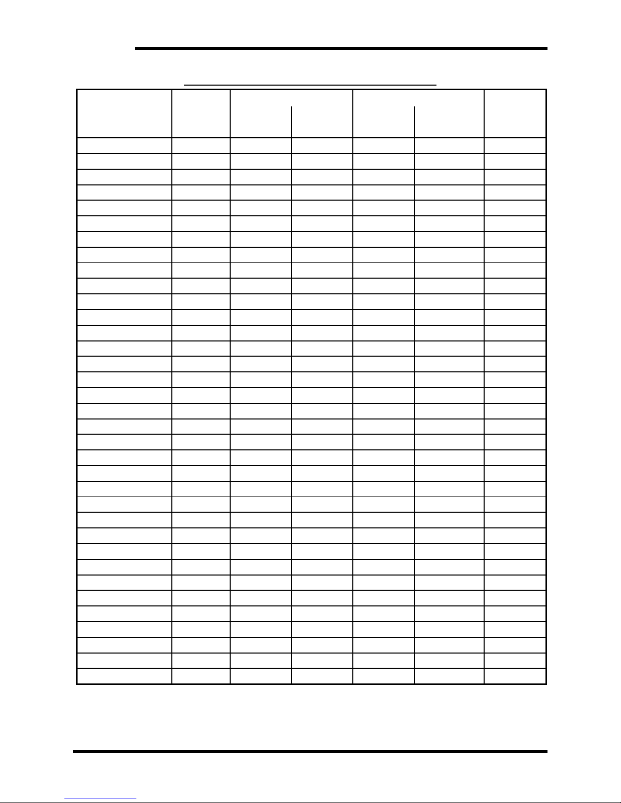
Table 6-2: Ratings and Specifications – 380VAC
ODEL NUMBERS
M3345-30SMF0 TYPE-1 10 10 7 7 436
M3345-30X*00 Open 10 6 7 4 287
M3345-30X*F0 Open 10 10 7 7 436
M3345-30BM00 TYPE-13 10 6 7 4 287
M3345-30BMF0 TYPE-13 10 10 7 7 436
M3345-31SMF0 TYPE-1 20 20 15 15 734
M3345-31X*00 Open 20 6 15 4 287
M3345-31X*F0 Open 20 20 15 15 734
M3345-31BM00 TYPE-13 20 6 15 4 287
M3345-31BMF0 TYPE-13 20 20 15 15 734
M3345-32SMF0 TYPE-1 30 20 22 15 734
M3345-32X*00 Open 30 6 22 4 287
M3345-32X*F0 Open 30 20 22 15 734
M3345-32BM00 TYPE-13 30 6 22 4 287
M3345-32BMF0 TYPE-13 30 20 22 15 734
M3345-32CMFM TYPE-13 30 30 22 22 1107
M3345-32Y*F0 Open 30 30 22 22 1107
M3345-34SMF0 TYPE-1 45 30 33 23 1107
M3345-34X*00 Open 45 5 33 4 287
M3345-34X*F0 Open 45 20 33 15 734
M3345-34BM00 TYPE-13 45 5 33 4 287
M3345-34BMF0 TYPE-13 45 20 33 15 734
M3345-34CMFM TYPE-13 45 45 33 33 1592
M3345-34Y*F0 Open 45 45 33 33 1592
M3345-3AWMFM TYPE-1 60 55 45 41 1965
M3345-3AY*FM Open 60 49 45 36 1741
M3345-3ACMFM TYPE-13 60 55 45 41 1965
M3345-3AZ*FM Open 60 55 45 41 1965
M3345-35WMFM TYPE-1 90 55 67 41 1965
M3345-35Y*FM Open 90 48 67 36 1741
M3345-35CMFM TYPE-13 90 55 67 41 1965
M3345-35Z*FM Open 90 55 67 41 1965
M3345-36VMFM TYPE-1 120 81 89 60 2711
M3345-36CMFM TYPE-13 120 81 89 60 2711
M3345-36Z0FM Open 120 81 89 60 2711
* an “M” in this place denotes a Current Meter is included, a “0” indicates Current Meter is not included.
CHASSIS
STYLE
PEAK
CURRENT
CONT.
CURRENT
BRAKING CONTINUOUS
MAX WATT
LOSS
DC REGEN RATED HP
26
Page 33
User’s Manual
Table 6-3: Ratings and Specifications – 460VAC
ODEL NUMBERS
M3345-40SMF0 TYPE-1 10 10 9 9 436
M3345-40X*00 Open 10 6 9 5 287
M3345-40X*F0 Open 10 10 9 9 436
M3345-40BM00 TYPE-13 10 6 9 5 287
M3345-40BMF0 TYPE-13 10 10 9 9 436
M3345-41SMF0 TYPE-1 20 20 18 18 734
M3345-41X*00 Open 20 6 18 5 287
M3345-41X*F0 Open 20 20 18 18 734
M3345-41BM00 TYPE-13 20 6 18 5 287
M3345-41BMF0 TYPE-13 20 20 18 18 734
M3345-42SMF0 TYPE-1 30 20 27 18 734
M3345-42X*00 Open 30 6 27 5 287
M3345-42X*F0 Open 30 20 27 18 734
M3345-42BM00 TYPE-13 30 6 27 5 287
M3345-42BMF0 TYPE-13 30 20 27 18 734
M3345-42CMFM TYPE-13 30 30 27 27 1107
M3345-42Y*F0 Open 30 30 27 27 1107
M3345-44SMF0 TYPE-1 45 30 41 27 1107
M3345-44X*00 Open 45 5 41 5 287
M3345-44X*F0 Open 45 20 41 18 734
M3345-44BM00 TYPE-13 45 5 41 5 287
M3345-44BMF0 TYPE-13 45 20 41 18 734
M3345-44CMFM TYPE-13 45 45 41 41 1592
M3345-44Y*F0 Open 45 45 41 41 1592
M3345-4AWMFM TYPE-1 60 55 54 50 1965
M3345-4AY*FM Open 60 49 54 44 1741
M3345-4ACMFM TYPE-13 60 55 54 50 1965
M3345-4AZ*FM Open 60 55 54 50 1965
M3345-45WMFM TYPE-1 90 55 81 50 1965
M3345-45Y*FM Open 90 48 81 43 1741
M3345-45CMFM TYPE-13 90 55 81 50 1965
M3345-45Z*FM Open 90 55 81 50 1965
M3345-46VMFM TYPE-1 120 81 108 73 2711
M3345-46CMFM TYPE-13 120 81 108 73 2711
M3345-46Z0FM Open 120 81 108 73 2711
* an “M” in this place denotes a Current Meter is included, a “0” indicates Current Meter is not included.
CHASSIS
STYLE
PEAK
CURRENT
CONT.
CURRENT
BRAKING CONTINUOUS
MAX WATT
LOSS
DC REGEN RATED HP
27
Page 34
M3345
A NOTE ON HP RATINGS
The Braking hp rating is dependent on the transistors, diodes, snubbers, and fuses
provided with the module. It is a function of the DC bus amp rating and indicates the
maximum hp that the module is designed to dissipate. Modules are able to provide
full Braking hp for at least 60 seconds. Modules can provide less than full Braking
hp for longer times.
The Continuous hp rating is a function of package style, heatsinks, and cooling
fans. This rating is always equal to or less than the Braking hp rating. For
applications the following must exist:
Continuous Regen hp rating ≥ Required hp rating * Duty Cycle
6.2. WATT LOSS
Tables 6-1 thru 6-3 list the maximum Watt/Loss generated by each of the listed
Regen units. When installing Regen units in an additional enclosure, consideration
should be given to internal temperature rise. The Watt/Loss rating in these tables is
based upon the maximum regen capability of each unit. Applications that do not
utilize the full capacity may be calculated as follows:
hp*746*5%+100 = Watt Loss
Where hp is the average estimated regen horsepower
6.3. CERTIFICATIONS
There are presently no certifications for the M3345 Regen Unit. If certification is
required, check with your integrator and/or panel shop for full system certification.
The M3345 is constructed with industry guidelines and safety taken into
consideration. If information is required for certification please contact Bonitron with
your request.
6.4. FUSE/CIRCUIT BREAKER SIZING AND RATING
• Only replace fuses with original type and rating.
• Due to the current limit control capability, blown fuses typically indicate internal
device failure or severe transient absorption event.
Table 6-4: Replacement Fuses
REGEN MODULE CURRENT
RATING
10 Amps A60Q15 A60Q15
20 Amps A60Q25 A60Q25
30 Amps (B, S, X chx) A60Q30 FWP-40
30 Amps (C, Y, Z chx) FWP-35 FWP-40
45 Amps (B, S, X chx) A60Q40 FWP-50
C LINE INPUT
A
REPLACEMENT FUSE
REPLACEMENT FUSE
C BUS OUTPUT
D
45 Amps (C, Y, Z chx) FWP-50 FWP-60
60 Amps FWP-70 FWP-80
90 Amps FWP-100 FWP-100
120 Amps FWP-125 FWP-125
28
Page 35
User’s Manual
6.5. DIMENSIONS AND MECHANICAL DRAWINGS
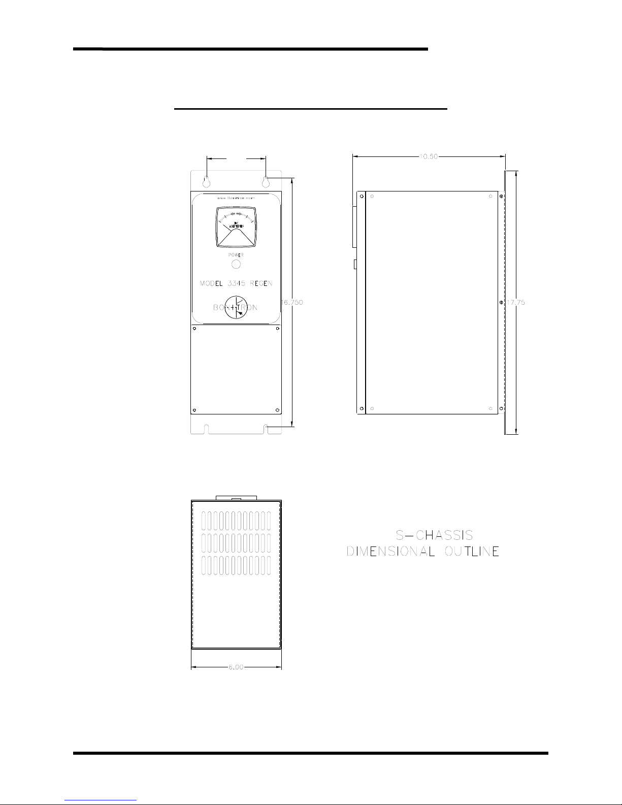
Figure 6-1: M3345 “S” Chassis Dimensional Outline
(APPROX.)
4.000
Dwg #: 010074 Rev: 20070521
29
Page 36
M3345
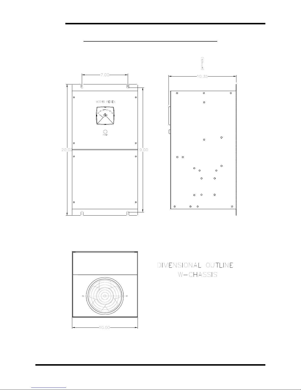
Figure 6-2: M3345 “W” Chassis Dimensional Outline
30
Dwg #: 060230 Rev: 20070521
Page 37
User’s Manual
Figure 6-3: M3345 “V” Chassis Dimensional Outline
Dwg #: 070107 Rev: 20070521
31
Page 38
M3345
Figure 6-4: M3345 “B” Chassis Dimensional Outline
32
Dwg #: 920306 Rev: 20080310
Page 39
User’s Manual
Figure 6-5: M3345 “B” Chassis with Fan Dimensional Outline
Dwg #: 940040 Rev: 20080310
33
Page 40
M3345
Figure 6-6: M3345 “C” Chassis Dimensional Outline
34
Dwg #: 950191 Rev: 20091229
Page 41
User’s Manual
Figure 6-7: M3345 “X” Chassis Dimensional Outline
Dwg #: 920322 Rev: 20080311
35
Page 42
M3345
Figure 6-8: M3345 “X” Chassis with Fan Dimensional Outline
36
Dwg #: 940190 Rev: 20080311
Page 43
User’s Manual
Figure 6-9: M3345 “Y” Chassis Dimensional Outline
Dwg #: 950052 Rev: 20070928a
37
Page 44
M3345
Figure 6-10: M3345 “Z” Chassis Dimensional Outline
38
Dwg #: 950246 Rev: 20000927 mod
Page 45
User’s Manual
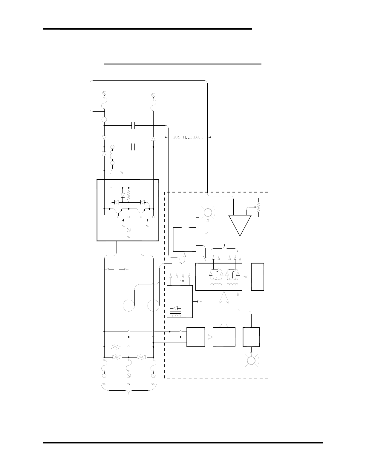
6.6. BLOCK DIAGRAM
Figure 6-11: Line Regen Functional Block Diagram
(+)
DC
BUS
INPUT
+-
A
di/dt LIMITER
1 OF 3
POWER CONTROL MODUL E
6uf
1500V
1200V
.33uf
TO
OTHER
PHASES
1B
1E
2B
A
A
(-)
B++
BUS REF
ON
LED
WHEN UNIT IS
BUS
IN CURRENT LIMIT
BASE
ISOLATED
1
1
E
B
LIMITI
SENSING
VOLTAGE
DRIVE
2
2
B
E
CURRENT
LIMIT
SENSING
2E
A
TRACKING
BOARD
CONTROL
LLV
1 OF 3
ISOLATED
REG
COM
+12V
B++
UN REG
POWER
CTB
A
3Ø AC
CTC
B
INPUT
50HZ OR
C
60HZ
SUPPLY
GATE DRIVE
-10V
B++
UNREG. REF.
PHASE
SENSING
ISOLATED
OPTICALLY
TIMING
LOGIC
CARRIER
FREQ. GEN.
BASE DRIVE
DELAY
LOW P.S.
LOCK OUT
START-UP
ON
WHEN RUNNING
LED
RUN
Dwg #: 000253 Rev: 20000830
39
Page 46

M3345
This page intentionally left blank
40
Page 47

User’s Manual
K
7. APPENDIX
7.1. APPLICATION NOTES
7.1.1. SIZING THE LINE REGENERATION CONTROL
Since the regeneration kit must direct energy from the DC bus back to the
power system, it is sized for the amount of DC bus current which it must
carry. To obtain the amount of DC bus current needed during deceleration;
the load and motor inertias, desired change in RPM, and required stopping
time must be known. With these application variables, the following
calculations can be made to size the regeneration unit. Use the equation
below to establish the torque required to decelerate or stop a rotating
object.
T =
where:
T = Torque required (lb-ft)
2
= Total inertia load to be decelerated (lb-ft)
W
ΔN
= Change in speed (rpm)
t = Time to decelerate load (sec)
Calculate the horsepower required at maximum speed.
P =
where:
P = Power (Hp)
T = Torque (lb-ft) (calculated above)
N = Maximum shaft speed (rpm)
Determine the DC bus current rating required for the regeneration module.
IDC = P(1.2) for 460vac drives
or: IDC = P(2.4) for 230vac drives
where: P = Power (Hp) (calculated above)
IDC = Regen Amps
2
)
( Δ
t
308
TN
5250
NWK
7.1.2. CALCULATING ENERGY SAVINGS
The regeneration kit directs energy from the mechanical load to the power
distribution line, where the energy is available to other connected loads.
These units provide system energy savings over dynamic braking kits,
because the net energy required from the distribution system is reduced by
the excess energy. Additional savings also occur when there is a need to
provide air conditioning with a DB kit and from reduced time spent stopping
loads.
To calculate the savings; the regeneration duty cycle, the length of
operation, the regen Hp, and the cost of energy must be known. With
these application variables, the following calculation may be made to
determine the cost savings:
$S = P(0.746)(t/T)(D)(H)($kW)
41
Page 48

M3345
7.1.3. SAVINGS EXAMPLE
where: $S = Savings
P = Power (Hp)
D = Number of days
H = Number of hours per day
t/T = Percent on time
$kW = Cost per kW
A 20 Amp, Model M3345-41SMF0, has been selected for use in braking a
high inertia centrifuge with the following characteristics. Calculate the
energy savings over a DB kit.
P =
20 Hp peak, 15 Hp average during
deceleration
D = 365 days
H = 10 hours per day
t/T = 5(on)/15(total)
$kW = $0.08 per kW
using:
$S = 15(0.746)(5/15)(365)(10)($0.08))
Savings per year is:
$S = $1,089.16
Using the regen module, the centrifuge customer is also able to reduce the
braking time from 5 minutes to 1.5 minutes. This results in a 30% increase
in throughput for the machine and produces additional cost savings for the
customer.
42
Page 49

User’s Manual
NOTES
43
Page 50

M3345
NOTES
44
Page 51

Page 52

D_M3345_CMAN_vall_05b 09/13/2011
521 Fairground Court ● Nashville, Tennessee 37211
 Loading...