

Page 1
-1-
MEITRACK_MV
T380_User_Gui
de_V2.5File Name:
Project:
Sub Project:
Revision:
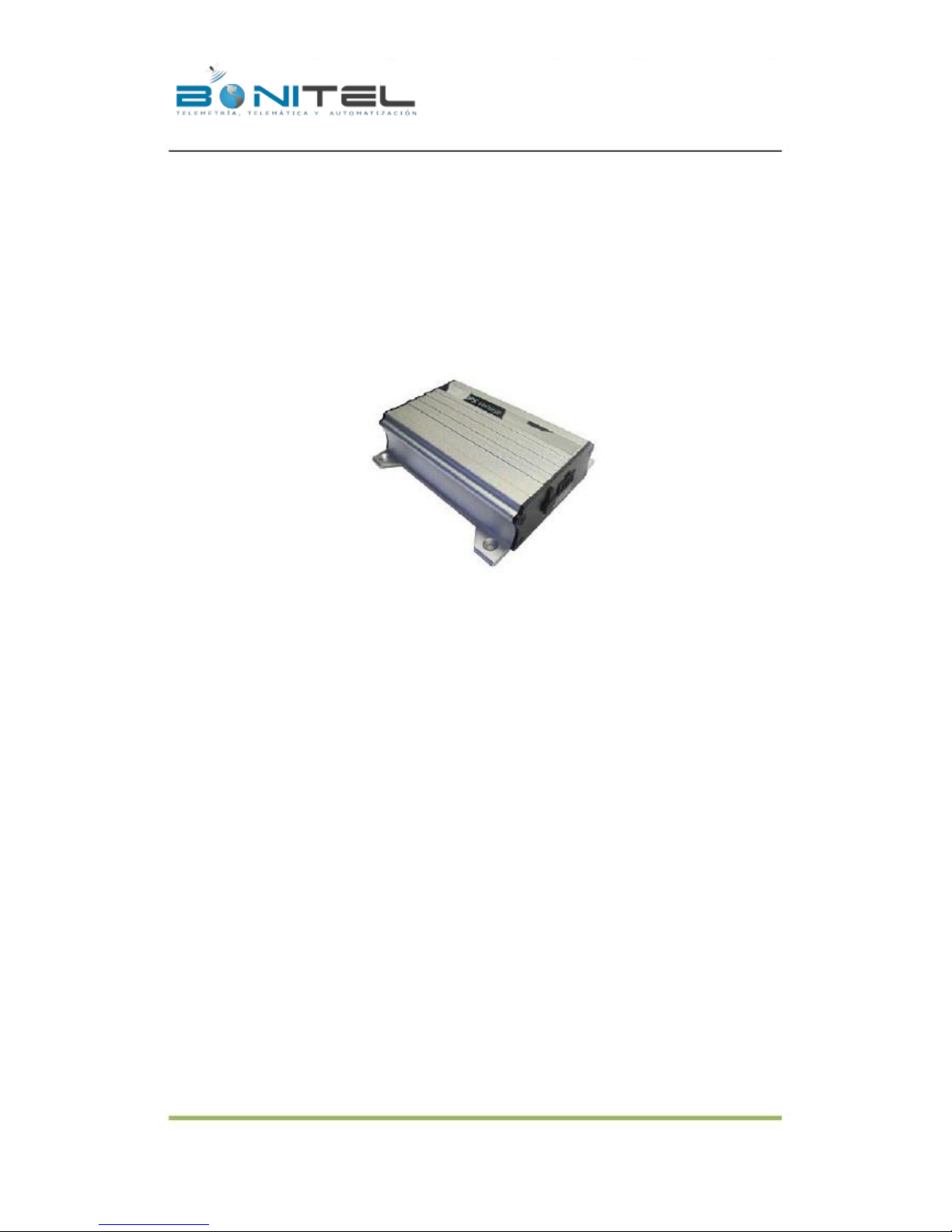
MEITRACK MVT340 User Guide
MVT340
User Guide
V2.7
Creator:
Creation Date:
Update Date:
Page:
Confidential:
2010-08-26
2013-01-31
- 1 - of 18
External Documentation
GPS Vehicle Tracker
User Guide V2.7
MVT340
-1-
BONITEL EIRL F: 325 7401 – RPC 987583073 – RPM #970400 - NEXTEL 120*2607
Page 2

File Name:
Project:
Sub Project:
Revision:
MEITRACK MVT340 User Guide
MVT340
User Guide
V2.7
Creator:
Creation Date:
Update Date:
Page:
Confidential:
Cavana Cheung
2010-08-26
2013-01-31
- 2 - of 18
External Documentation
Contents
1.
2.
3.
Copyright and Disclaimer .............................................................................................................................. - 3 -
Applications .................................................................................................................................................. - 3 -
Product Function and Specifications............................................................................................................. - 3 -
3.1 Product Function ...................................................................................................................................... - 3 -
3.2 Specifications ........................................................................................................................................... - 4 -
4.
5.
6.
MVT340 and Accessories .............................................................................................................................. - 4 -
View .............................................................................................................................................................. - 5 -
First Use ........................................................................................................................................................ - 5 -
6.1 Install SIM Card ........................................................................................................................................ - 5 -
6.2 Charging ................................................................................................................................................... - 5 -
6.3 LED Indications ......................................................................................................................................... - 5 -
6.4 Track by Calling ......................................................................................................................................... - 6 -
6.4.1 Multiple Phone numbers– A71 ..................................................................................................... - 7 -
6.4.2 Sleep Mode – A73 ......................................................................................................................... - 8 -
6.4.3 Geo-fence Alarm – B05.................................................................................................................. - 8 -
6.4.4 Set Anti-theft– B21 ........................................................................................................................ - 9 -
6.4.5 Time Zone– B35 ............................................................................................................................ - 9 -
6.5 Configure by Computer ............................................................................................................................ - 9 -
6.5.1 SMS Tracking ............................................................................................................................... - 11 -
6.5.2 GPRS Tracking .............................................................................................................................. - 13 -
7.
Installation .................................................................................................................................................. - 16 -
7.1 Install I/O Cable ...................................................................................................................................... - 16 -
7.1.1 POWER/GND (PIN1, PIN2) ........................................................................................................... - 16 -
7.1.2 Digital Input (PIN3, Negative Triggering) ..................................................................................... - 17 -
7.1.3 Digital Input (PIN5, Positive Triggering) ....................................................................................... - 17 -
7.1.4 Output (PIN8) .............................................................................................................................. - 17 -
7.1.5 Analog Input (PIN7) ..................................................................................................................... - 17 -
7.2 Install GPS/GSM Antenna ....................................................................................................................... - 18 -
7.3 Mount the MVT340 unit ........................................................................................................................ - 18 -
-2-
BONITEL EIRL F: 325 7401 – RPC 987583073 – RPM #970400 - NEXTEL 120*2607
Page 3

File Name:
Project:
Sub Project:
Revision:
MEITRACK MVT340 User Guide
MVT340
User Guide
V2.7
Creator:
Creation Date:
Update Date:
Page:
Confidential:
Cavana Cheung
2010-08-26
2013-01-31
- 3 - of 18
External Documentation
1. Copyright and Disclaimer
Copyright © 2013 BONITEL. All rights reserve
The user manual may be changed without prior notification.
This user manual, or any part thereof, may not be reproduced for any purpose whatsoever without the written
authorization of BONITEL, or transmitted in any form, either electronically or mechanically, including
photocopying and recording.
In no event shall BONITEL be liable for direct, indirect, special, incidental, or consequential damages
(including but not limited to economic loss, personal injury, and loss of asset and property) arising out of the use
or inability or illegality to use the product or documentation.
2. Applications
Vehicle Real Time Tracking
Car Security/Anti-Hijack
Fleet Management
3. Product Function and Specifications
3.1 Product Function
SiRF III GPS and Quad Band GSM 850/900/1800/1900Mhz
AGPS ( with GSM Base Station ID)
Track by SMS/GPRS (TCP/UDP) (MEITRACK Protocol)
Track on Demand
Track by Time Interval
Track by Distance Interval
Track on Mobile Phone
Inbuilt Motion Sensor
850mAh Internal Backup Battery
SOS Alarm
Geo-fence Alarm
GPS Blind Area Alarm
Low Battery Alarm
Speeding Alarm
Tow Alarm
GPS Antenna Cut Alarm
External Power Cut Alarm
Mileage Report
-3-
BONITEL EIRL F: 325 7401 – RPC 987583073 – RPM #970400 - NEXTEL 120*2607
Page 4
File Name:
Project:
Sub Project:
Revision:
MEITRACK MVT340 User Guide
MVT340
User Guide
V2.7
Creator:
Creation Date:
Update Date:
Page:
Confidential:
Cavana Cheung
2010-08-26
2013-01-31
- 4 - of 18
External Documentation
Engine Cut (Engine immobilization)
Inbuilt Super Magnet (optional)
2 Digital Inputs (negative/positive triggering), 1 Output.
1 Analog Input Detection
3.2 Specifications
Items
Dimension
Weight
Input Voltage
Back-up Battery
Power
consumption
Operating
Temperature
Humidity
Work Time
LED
Button
Microphone
Memory
Sensor
GSM Frequency
GPS Chip
GPS Sensitivity
Positioning
Accuracy
I/O
2 Digital Input (1 negative triggering and 1 positive triggering)
1 Analog Input Detection
1 Output
1 USB port for configuration only
5%~95%
43 hours in power-saving mode and 10 hours in normal mode
2 LED lights to show GPS, GSM and other status
1 SOS and 1 power on/off
None
None
Motion Sensor
GSM 850/900/1800/1900MHz
Latest GPS SIRF-Star III chipset
-159dB
10 meters, 2D RMS
-20℃~55℃
Specifications
110x72x39mm
170g
DC 9V~36V/1.5A
850mAh/3.7V
65mA standby current
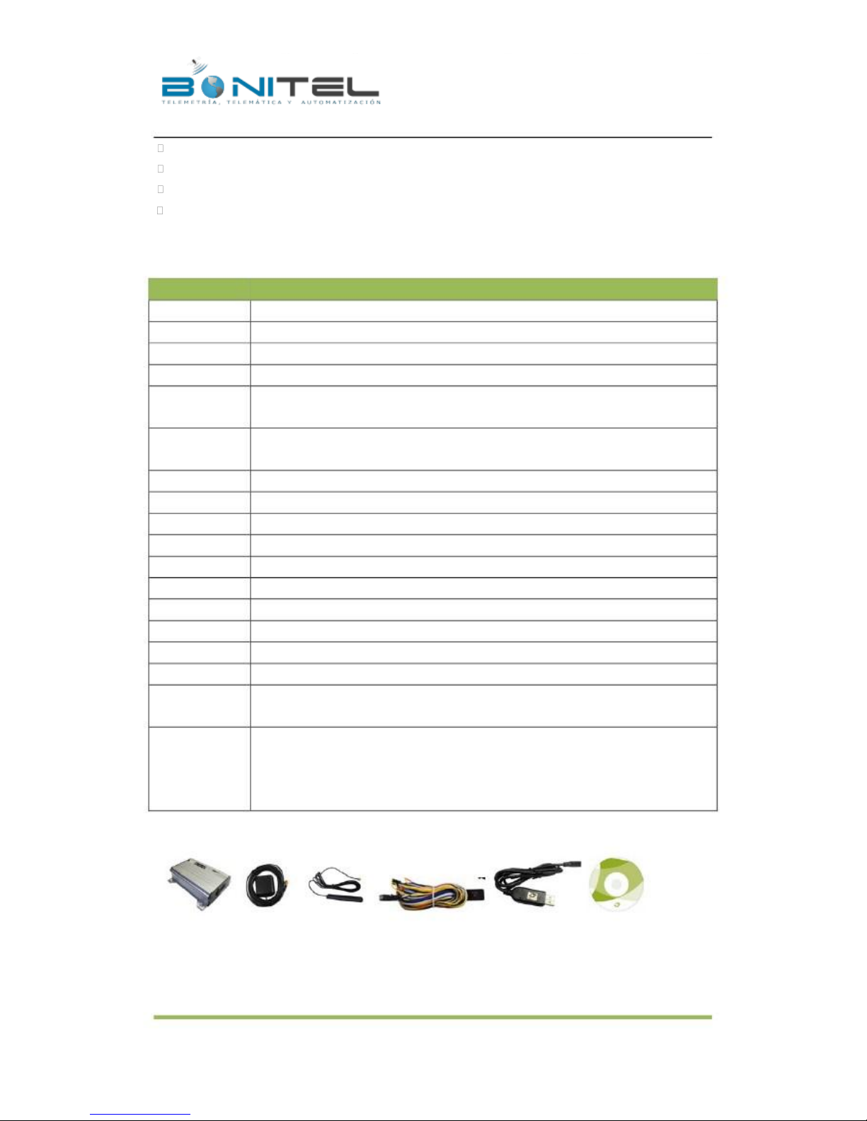
4. MVT340 and Accessories
MVT340 with
Battery
GPS
Antenna
GSM
Antenna
I/O Cable +
SOS Button
USB Data Cable
CD
-4-
BONITEL EIRL F: 325 7401 – RPC 987583073 – RPM #970400 - NEXTEL 120*2607
Page 5
File Name:
Project:
Sub Project:
Revision:
MEITRACK MVT340 User Guide
MVT340
User Guide
V2.7
Creator:
Creation Date:
Update Date:
Page:
Confidential:
Cavana Cheung
2010-08-26
2013-01-31
- 5 - of 18
External Documentation
5. View
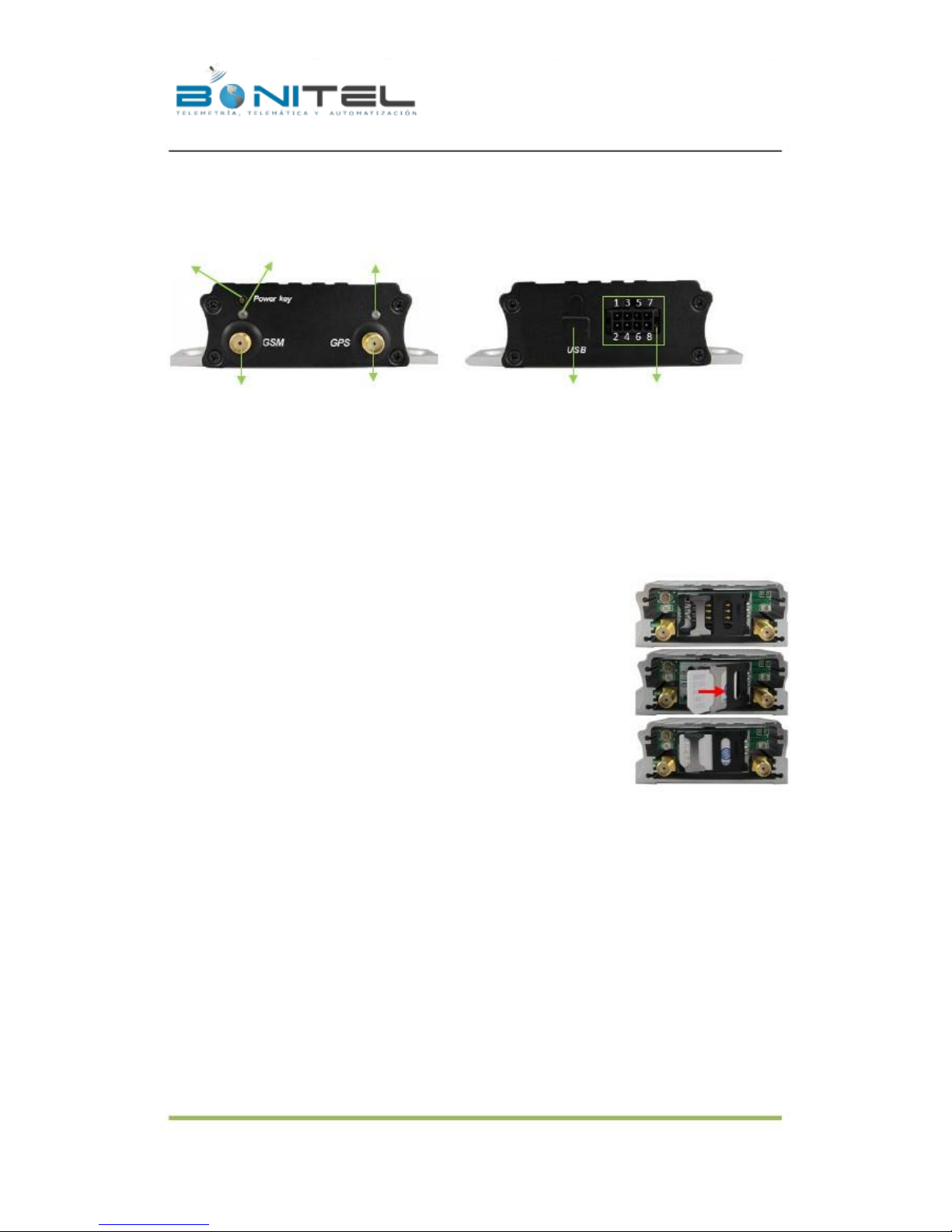
On/Off
GPS LED
GSM LED
GSM Antenna
GPS Antenna
USB Port
PIN (Power, I/O)
6. First Use
6.1 Install SIM Card
Check that the SIM has not run out of credit (test the SIM in a phone to make sure it
can send and receive SMS);
Check that the SIM Lock code is turned off;
If you require the function of sending an SMS location report to the authorized
phone number when it makes a call to the MVT340, please make sure the SIM
installed supports displaying caller ID.
Before installing the SIM card, turn off the power for MVT340.
Unscrew and remove cover.
Insert the SIM card by sliding it into the card holder with the chip module facing to
the connectors on PCB.
Put back the cover and screw it up.
6.2 Charging
Please connect GND (-Black) and Power (+Red) wires to 12V or 24 external power and make sure to charge the
battery for at least 3 hours. 8 hours is highly appreciated.
Configuration and testing suggested prior to installation.
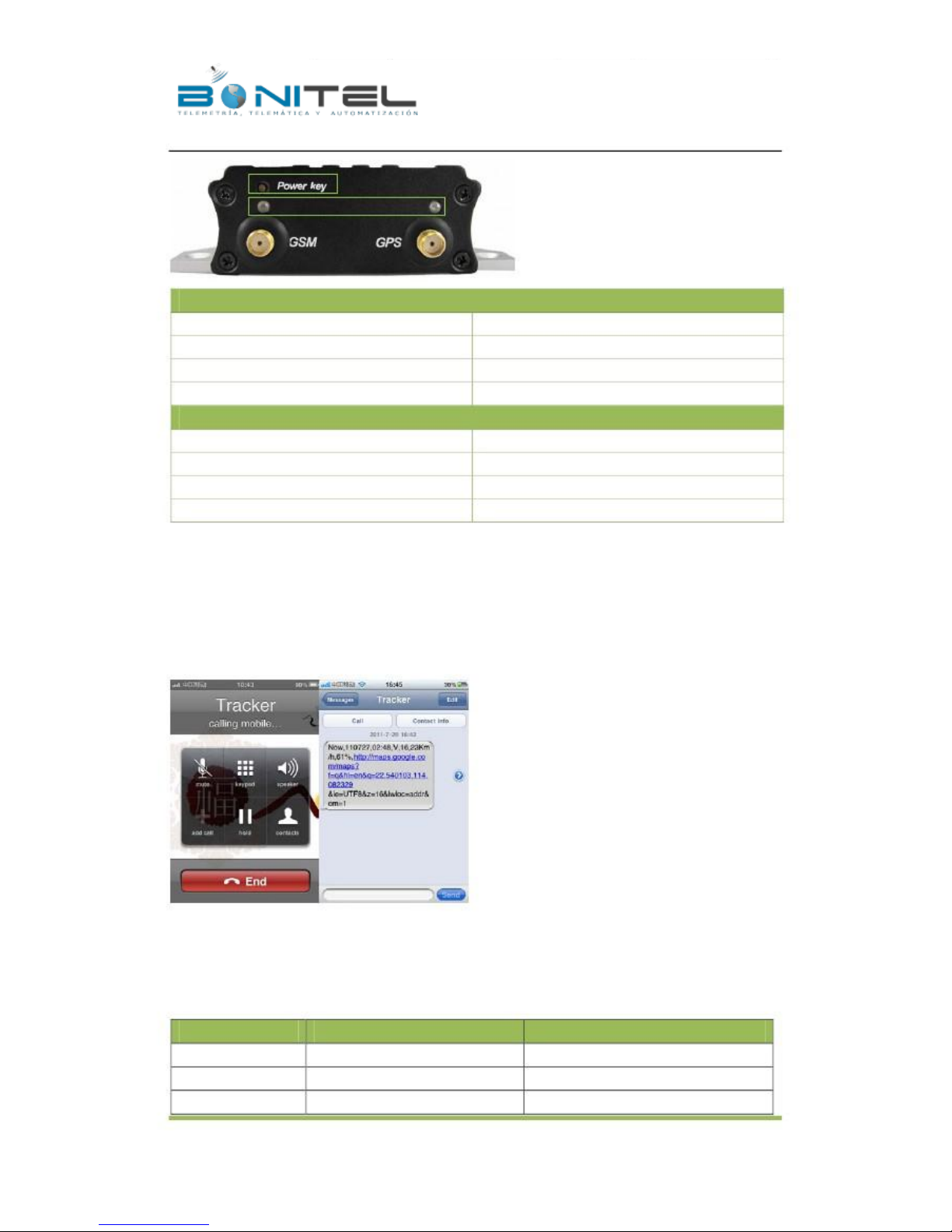
6.3 LED Indications
Press and hold the Power On/Off button for 3~5 seconds to turn on/off MVT340.
-5-
BONITEL EIRL F: 325 7401 – RPC 987583073 – RPM #970400 - NEXTEL 120*2607
Page 6
File Name:
Project:
Sub Project:
Revision:
MEITRACK MVT340 User Guide
MVT340
User Guide
V2.7
Creator:
Creation Date:
Update Date:
Page:
Confidential:
Cavana Cheung
2010-08-26
2013-01-31
- 6 - of 18
External Documentation
GPS LED (Blue)
On
Flashing ( every 0.1 second)
Flashing (0.1 second on and 2.9 seconds off)
Flashing (1 second on and 2 seconds off)
GSM LED (Green)
On
Flashing ( every 0.1 second)
Flashing (0.1 second on and 2.9 seconds off)
Flashing (1 second on and 2 seconds off)
A call is coming in / a call is being made
Initializing
MVT340 is connected to the GSM network
MVT340 is not connected to the GSM network
One button is pressed or input is active.
Initializing or back-up battery power is low
MVT340 has a GPS fix
MVT340 has no GPS fix
6.4 Track by Calling
Make a call to MVT340 and it will report with one SMS.
For example,
Now,110727 02:48,V,16,23Km/h,61%,http://maps.google.com/maps?f=q&hl=en&q=22.540103,114.082329
&ie=UTF8&z=16&iwloc=addr&om=1
Click on the link then the location can be shown directly on Google Maps on your mobile phone.
Report description:
Now,110727 02:48,V,16,23Km/h,61%,http://maps.google.com/maps?f=q&hl=en&q=22.540103,114.082329
&ie=UTF8&z=16&iwloc=addr&om=1
Content
Now
110721 16:40
V
Description
Current Location
Date & Time: 21 July, 2011, 16:40pm
No GPS fixed
Note
Alarm Type
Date & Time in YYMMDD HH:MM
GPS Status Indicator:
-6-
BONITEL EIRL F: 325 7401 – RPC 987583073 – RPM #970400 - NEXTEL 120*2607
Page 7
File Name:
Project:
Sub Project:
Revision:
MEITRACK MVT340 User Guide
MVT340
User Guide
V2.7
Creator:
Creation Date:
Update Date:
Page:
Confidential:
Cavana Cheung
2010-08-26
2013-01-31
- 7 - of 18
External Documentation
A = valid, V = invalid
10
0Km/h
97%
http://maps.google.c
om/maps?f=q&hl=en
&q=22.540103,114.0
82329
&ie=UTF8&z=1
6&iwloc=addr&om=1
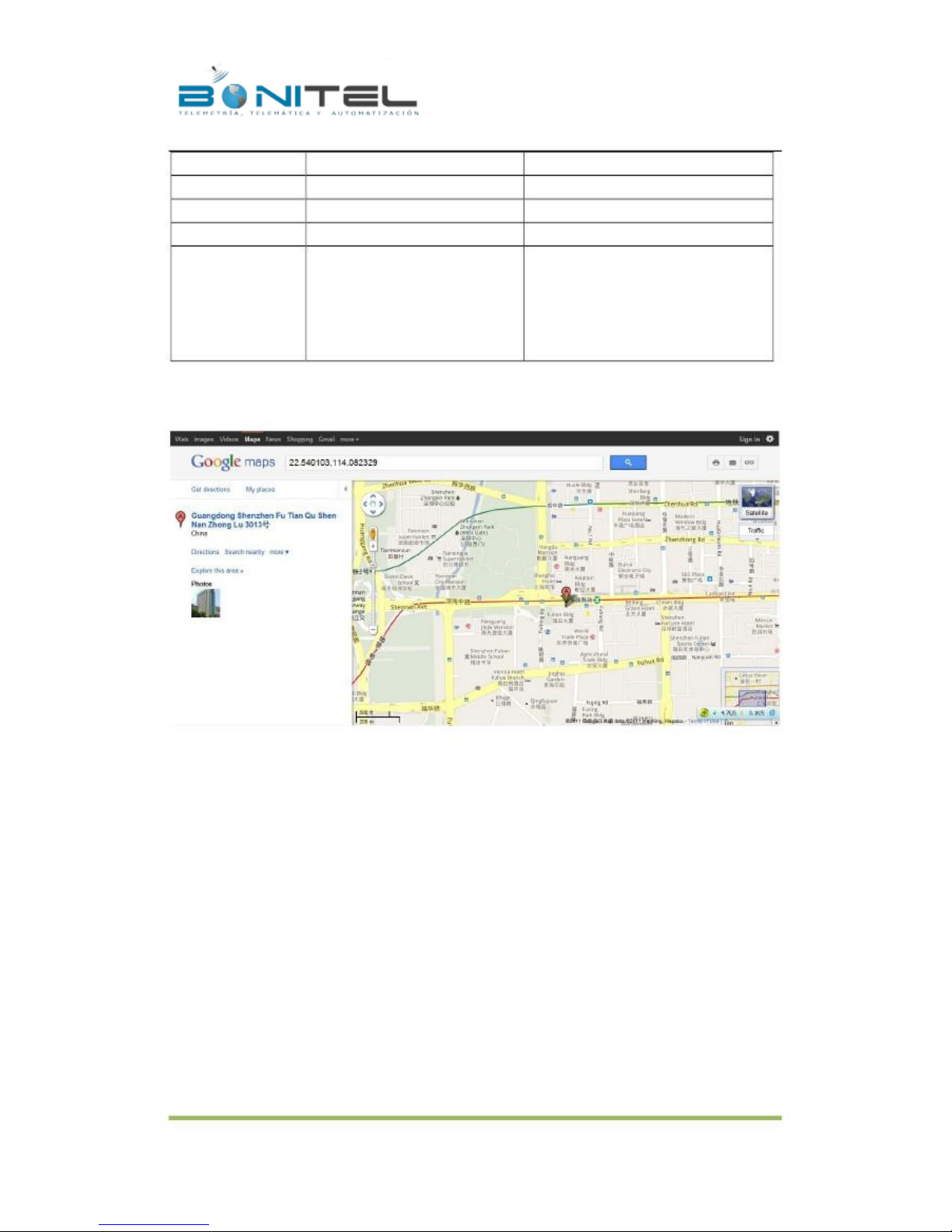
If your mobile cannot visit HTTP websites, input the latitude and longitude into Google Maps as the following
picture shows to get the position:
Latitude: 22.513015
Longitude: 114.057235
GSM signal=10
Speed=0
Battery Power: 97%
GSM Signal. Decimal Digit (0~31)
KM/h. Decimal digit
Battery Power Balance (Percentage)
Google Maps Web Link with Latitude and
Longitude. Click on the link to get the
location.
More SMS commands
You can configure MVT340 by mobile phone or by computer using the MEITRACK Parameter Editor.
For more details, please refer to part 6.5 Configure by Computer.
Note:
1.
2.
Password is 4 digits only and defaulted as 0000. You can change the password by Parameter Editor and SMS
command.
MVT340 will only accept commands from a user with the correct password and report SMS report to the user.
If preauthorized phone number was set, only this phone number can receive SMS reports.
6.4.1 Multiple Phone numbers– A71
Command: 0000, A71, phone number 1, phone number 2, phone number 3
SMS Get: IMEI, A71, OK
Note:
Authorize a phone number for SOS alarm, calling for location report, geo-fence alarm, and low battery alarm.
Phone Number: Max 16 characters.
-7-
BONITEL EIRL F: 325 7401 – RPC 987583073 – RPM #970400 - NEXTEL 120*2607
Page 8

File Name:
Project:
Sub Project:
Revision:
MEITRACK MVT340 User Guide
MVT340
User Guide
V2.7
Creator:
Creation Date:
Update Date:
Page:
Confidential:
Cavana Cheung
2010-08-26
2013-01-31
- 8 - of 18
External Documentation
If no preset phone number, it is empty (default is empty).
Send command “0000, A71” to delete all phone numbers.
When the SOS button is pressed, MVT340 will make a call to phone number 1, 2 and 3. It will stop calling when
one number answers.
Example: 0000,A71,13811111111,13822222222,13833333333
SMS Get: 353358017784062,A71,OK
6.4.2 Sleep Mode – A73
Command: 0000,A73,X
SMS Get: IMEI,A73,OK
Note:
This setting is for power saving.
X=0, turn off sleep mode (default)
X=1, normal sleep. GSM module work, GPS module work by sleep mode intermittently. The device can work 25%
longer than no sleep mode. Note: this is not recommended for users who set “track by interval” or short time
interval, because it will affect the completeness of tracking.
X=2, deep sleep, the tracker will enter this mode after it is inactive or stationary(No SOS/any triggered by the
button/input/incoming calls/message/movement) for 5 minutes. GPS module stops working and GSM module
enters sleep mode. The tracker remains in this mode until it is activated by SOS/any triggered by the
button/input/incoming calls/message/movement. After that, it will repeat above processes.
Note: In any condition, the device will directly quit the sleep mode and back to normal working mode by SMS or
GPRS command to turn off the sleep mode.
Example: 0000,A73,2
SMS Get: 353358017784062,A73,OK
6.4.3 Geo-fence Alarm – B05
Command: B05,P,latitude,longitude,radius,in,out
SMS Get: IMEI,B05,OK
Note:
P: 1 to 8. Max 8 Geo-fence waypoints can be set.
Latitude: Latitude in decimal degrees of the waypoint center.
Longitude: Longitude in decimal degrees of the waypoint center.
Radius: [1, 4294967295] in meters.
In = 0, turn off the alarm when the tracker enters the waypoint;
In = 1, turn on the alarm when the tracker enters the waypoint.
Out = 0, turn off the alarm when the tracker exits the waypoint;
Out = 1, turn on the alarm when the tracker exits the waypoint.
Example: 0000,B05,1,22.91319,114.07988,1000,0,1
SMS Get: 353358017784062,B05,OK
-8-
BONITEL EIRL F: 325 7401 – RPC 987583073 – RPM #970400 - NEXTEL 120*2607
Page 9

File Name:
Project:
Sub Project:
Revision:
MEITRACK MVT340 User Guide
MVT340
User Guide
V2.7
Creator:
Creation Date:
Update Date:
Page:
Confidential:
Cavana Cheung
2010-08-26
2013-01-31
- 9 - of 18
External Documentation
Once the tracker goes outside of the circle (center: 22.91319,114.07988 and radius 1000 meters), the following
message will be received.
353358017784062,ExitGEO,22.918186,114.089823,080229123816,A,10,22,16,32,1,21,6667,850,,0000,,
6.4.4 Set Anti-theft– B21
Command: 0000,B21,Status
SMS Get: IMEI,B21,OK
Note:
Status=1, turn on Anti-theft (default); the device alarms when input 2 (positive input) is active;
Status=0, turn off Anti-theft; the device doesn’t alarm when input 2 (positive input) is active.
6.4.5 Time Zone– B35
Command: 0000,B35,T
SMS Get: IMEI,B35,OK
Note:
Default time of the tracker is GMT. You can use this command to change the time on your tracker to your local
time. This command is for SMS tracking only.
Time zone of SMS report is separated with that of GPRS data. If you need to set time zone in GPRS data, please
use SMS command: 0000, B36, T
T=0, to turn off this function.
T=[-32768,32767] to set time difference in minutes to GMT.
For those ahead of GMT, just input the time difference in minutes directly. For example, GMT+8,
W000000,032,480
‘-‘is required for those behind GMT. For example, W000000,032,-120.
Example: 0000,B35,480
SMS Get: 353358017784062,B35,OK
For more details regarding SMS commands, please refer to MEITRACK SMS Protocol.
6.5 Configure by Computer
This part mainly shows you how to use the MEITRACK Parameter Editor.
Note: Don’t connect MVT340 to external battery when configuring.
Please refer to the MEITRACK Parameter Editor User Guide for more information regarding configuration and
functions.
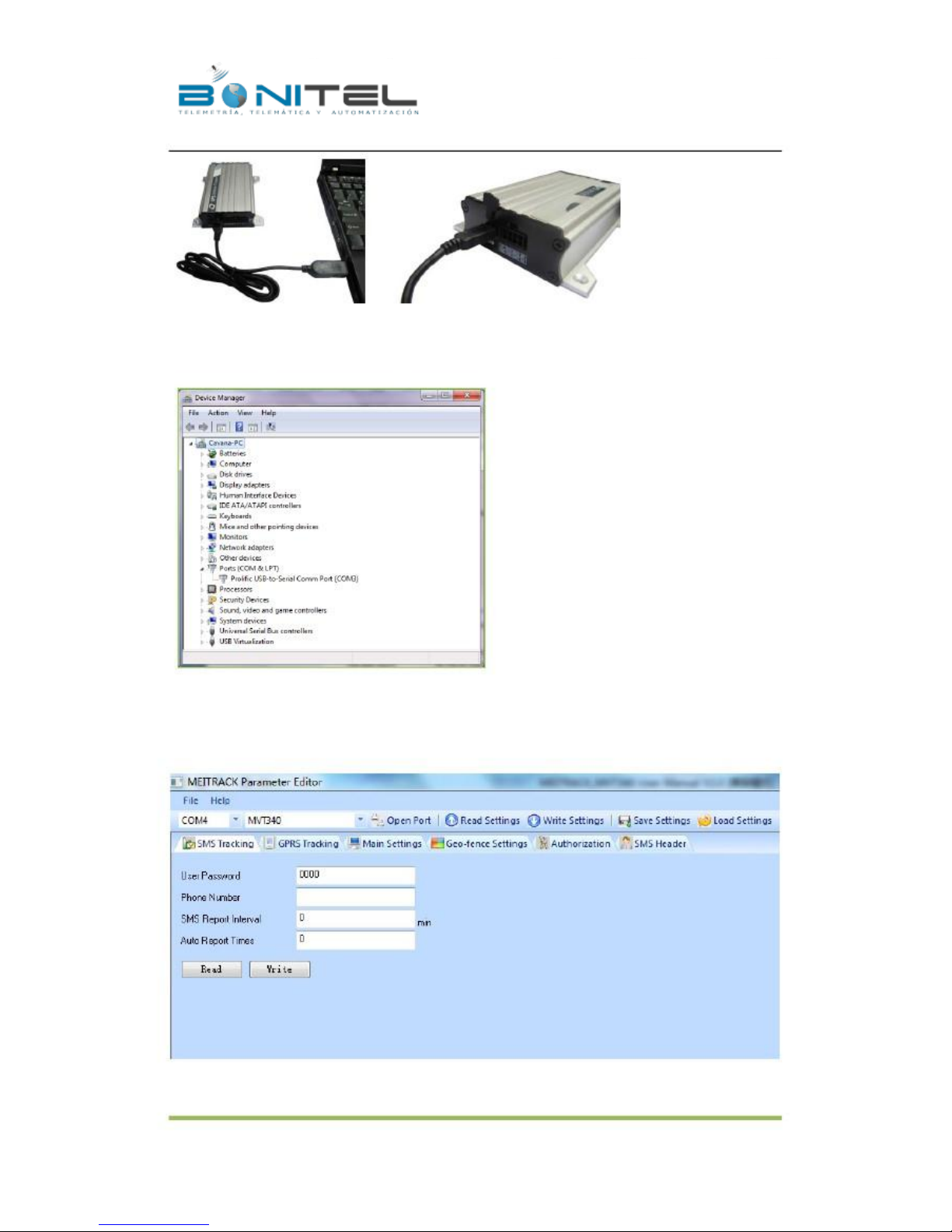
Run ‘PL2303_Prolific_DriverInstaller’ to install the driver for the USB data cable.
Note: PL2303_Prolific_DriverInstaller is in the folder ‘USB-232 Driver’ in the CD.
Connect the USB Data Cable between MVT340 and PC.
-9-
BONITEL EIRL F: 325 7401 – RPC 987583073 – RPM #970400 - NEXTEL 120*2607
Page 10
File Name:
Project:
Sub Project:
Revision:
MEITRACK MVT340 User Guide
MVT340
User Guide
V2.7
Creator:
Creation Date:
Update Date:
Page:
Confidential:
Cavana Cheung
2010-08-26
2013-01-31
- 10 - of 18
External Documentation
Open Device Manager (Device Manager is under Control Panel\System and Security\System). You can then find
‘Prolific USB-to-Serial Comm Port’ as the following picture shows.
Note: Remember this Com number. It needs to be input into the MEITRACK Parameter Editor. It is COM3 in this
example and it would be COM4 or COM5… in your computer.
Run ‘MEITRACK Parameter Editor.exe’ and the following configuration window will pop up:
Choose the correct Com number and terminal type in previous Device Manager then click the ‘Open Port’ button.
Click ‘Read Settings’ button to show the default or previous settings of the tracker.
- 10 -
BONITEL EIRL F: 325 7401 – RPC 987583073 – RPM #970400 - NEXTEL 120*2607
Page 11
File Name:
Project:
Sub Project:
Revision:
MEITRACK MVT340 User Guide
MVT340
User Guide
V2.7
Creator:
Creation Date:
Update Date:
Page:
Confidential:
Cavana Cheung
2010-08-26
2013-01-31
- 11 - of 18
External Documentation
Note: MEITRACK Parameter Editor is in the CD. The language will be automatically adjusted to be the same as
your PC operation system’s language. Please use “Ctrl+L” to change the language.
6.5.1 SMS Tracking
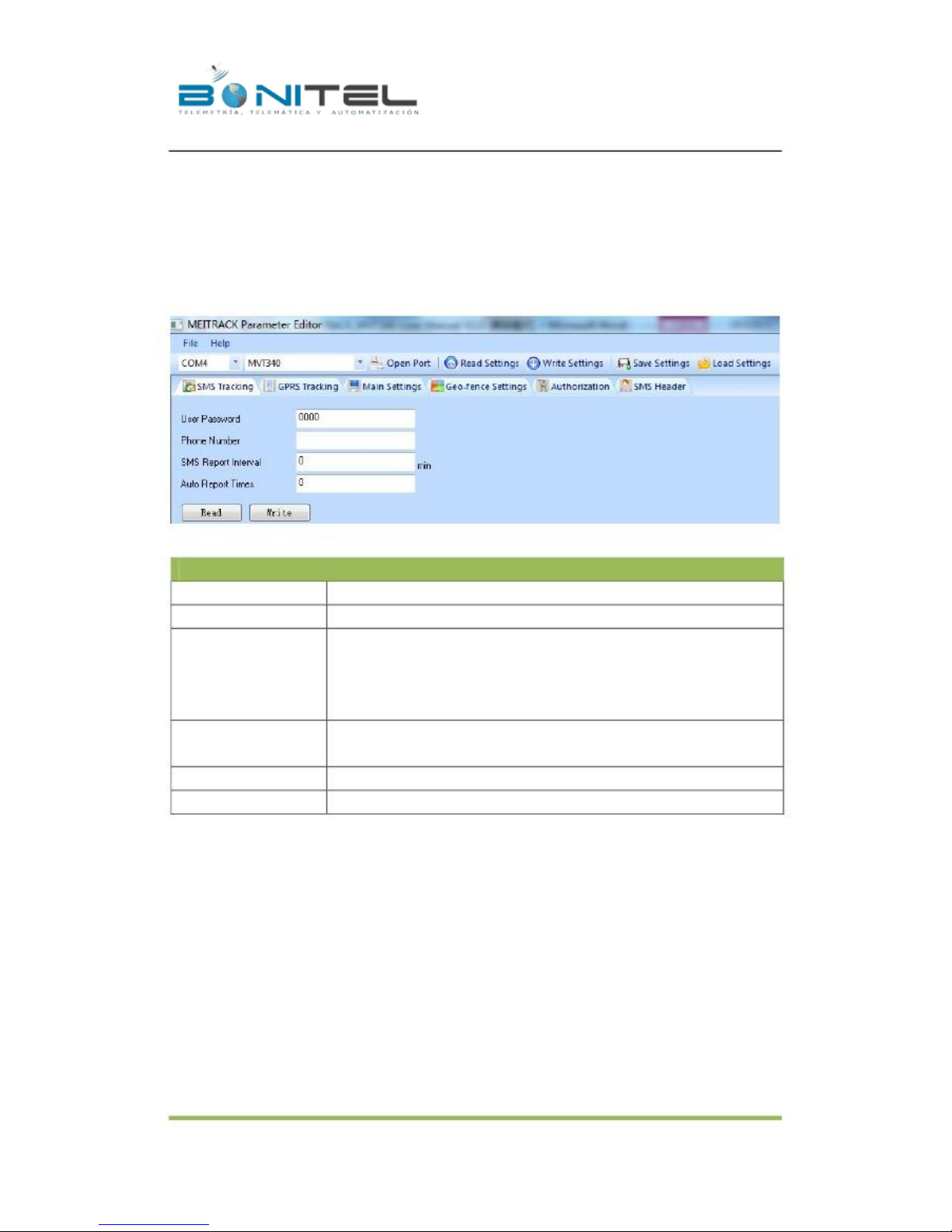
6.5.1.1 Track by Preset Interval
Click Tap I: SMS Tracking
Item
User Password
Phone Number
SMS Report Interval
Description
SMS password for sending SMS commands and defaulted as 0000.
A phone number to receive SMS location reports.
Track by time interval via SMS.
Set time interval for SMS location report.
= 0, stop tracking by time interval (default);
= [1,65535], track by interval in minute.
Auto Report Times
Read
Write
6.5.1.2 SMS Report
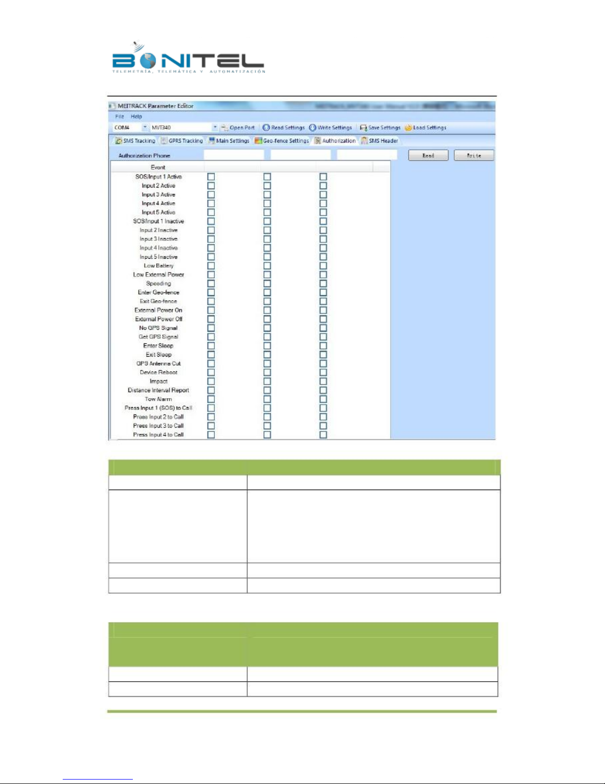
Click Tap V: Authorization
= 0, unlimited times for report.
= [1,255], it will stop reporting when reaching preset times
Read current tracker’s settings for above items.
Write above settings to the tracker.
- 11 -
BONITEL EIRL F: 325 7401 – RPC 987583073 – RPM #970400 - NEXTEL 120*2607
Page 12
File Name:
Project:
Sub Project:
Revision:
MEITRACK MVT340 User Guide
MVT340
User Guide
V2.7
Creator:
Creation Date:
Update Date:
Page:
Confidential:
Cavana Cheung
2010-08-26
2013-01-31
- 12 - of 18
External Documentation
Item
Authorization Phone
Event
Description
A phone number to receive selected event’s SMS reports.
Selected event’s SMS reports will be sent to authorized phone number.
For more details, please refer to MEITRACK GPRS/SMS Protocol.
For description of events from SOS/Input 1 Active to Tow Alarm,
please refer to tap II GPRS Tracking.
Other events description, please refer to below chart.
Read
Write
Event Description:
Event
Read current tracker’s settings for above items.
Write above settings to the tracker.
Description
(If the box is ticked, authorized phone number will get event report
by SMS or calling)
SOS/Input 1 Active
Input 2 Active
Report when input1 (SOS) is active/pressed.
Report when input 2 is active.
- 12 -
BONITEL EIRL F: 325 7401 – RPC 987583073 – RPM #970400 - NEXTEL 120*2607
Page 13

File Name:
Project:
Sub Project:
Revision:
MEITRACK MVT340 User Guide
MVT340
User Guide
V2.7
Creator:
Creation Date:
Update Date:
Page:
Confidential:
Cavana Cheung
2010-08-26
2013-01-31
- 13 - of 18
External Documentation
SOS/Input1 Inactive
Input 2 Inactive
Low Battery
Low External Power
Speeding
Enter Geo-fence
Exit Geo-fence
External Power On
External Power Off
No GPS Signal
Get GPS Signal
Enter Sleep
Exit Sleep
GPS Antenna Cut
Device Reboot
Heartbeat Report
Heading Change Report
Distance Interval Report
Tow Alarm
Press Input 1 (SOS) to call
Press Input 2 to call
Reject Incoming Call
Call for SMS Location Report
Report when input 1 inactive (SOS released).
Report when input 2 inactive.
Report when backup battery’s voltage is below 3.5V.
External power (car battery) is lower than predefined voltage.
You can define voltage in Main Settings.
Report when MVT340 speeds higher than the pre-set value.
Value can be changed on tap III Main Settings
Report when MVT340 enters Geo-fence.
Report when MVT340 exits Geo-fence.
Geo-fence can be changed on tap III Main Settings.
Alarm when external power supply is on or recover.
Alarm when external power supply if off or cut.
Report when MVT340 enters GPS blind area or no GPS signal.
Report when MVT340 exits GPS blind area or get GPS signal.
Report when MVT340 enters sleep mode.
Report when MVT340 exits sleep mode.
Sleep mode can be changed on tap III Main Settings.
Alarm when the GPS antenna is disconnected or cut
Report when MVT340 is rebooting.
Turn on heartbeat report
You can define heartbeat interval on tap III Main Settings.
Auto report when tracker’s direction changes over predefined angle
You can define angle degree on tap III Main Settings.
Track by distance.
Interval can be changed on tap III Main Settings.
Alarm when the tracker trembles for a period of time.
You can define tow time on tap III Main Settings.
Make a call to authorized phone number when press input 1 (SOS).
Make a call to authorized phone number when press input 2.
Hand up incoming call automatically from correspondent authorized
phone number.
Reject incoming call or report SMS location when no answer.
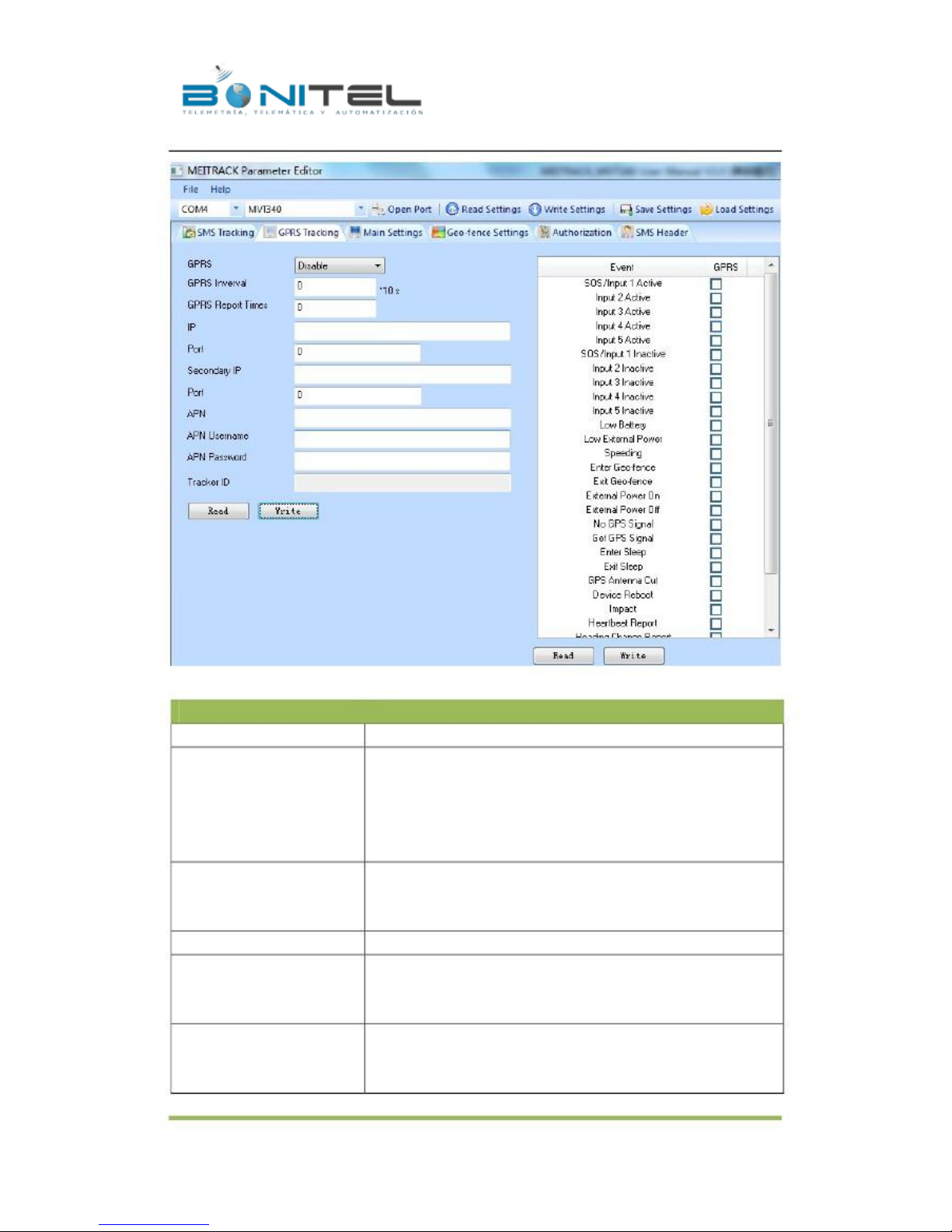
6.5.2 GPRS Tracking
Click Tap II: GPRS Tracking
- 13 -
BONITEL EIRL F: 325 7401 – RPC 987583073 – RPM #970400 - NEXTEL 120*2607
Page 14
File Name:
Project:
Sub Project:
Revision:
MEITRACK MVT340 User Guide
MVT340
User Guide
V2.7
Creator:
Creation Date:
Update Date:
Page:
Confidential:
Cavana Cheung
2010-08-26
2013-01-31
- 14 - of 18
External Documentation
Item
GPRS
GPRS Interval
Description
Select TCP/UDP to enable GPRS communication.
Track by time interval via GPRS.
Set time interval for GPRS tracking.
Interval is in unit of 10 seconds.
Interval = 0, stop tracking by time interval.
Max time interval = 65535*10 seconds
GPRS Report Times
= 0, report without limit.
= [1,65535], set report times, MVT340 will stop reporting when reaching
the times.
IP & Port
Secondary IP and Port
(Backup Server)
APN
APN user name
APN password
Input server’s IP address and port number.
Input backup server’s IP address and port number to avoid losing data
when main server is down. The backup server will receive data
automatically.
APN, APN username, APN password: max 32 bytes.
If no username and password required, leave them blank.
- 14 -
BONITEL EIRL F: 325 7401 – RPC 987583073 – RPM #970400 - NEXTEL 120*2607
Page 15
File Name:
Project:
Sub Project:
Revision:
MEITRACK MVT340 User Guide
MVT340
User Guide
V2.7
Creator:
Creation Date:
Update Date:
Page:
Confidential:
Cavana Cheung
2010-08-26
2013-01-31
- 15 - of 18
External Documentation
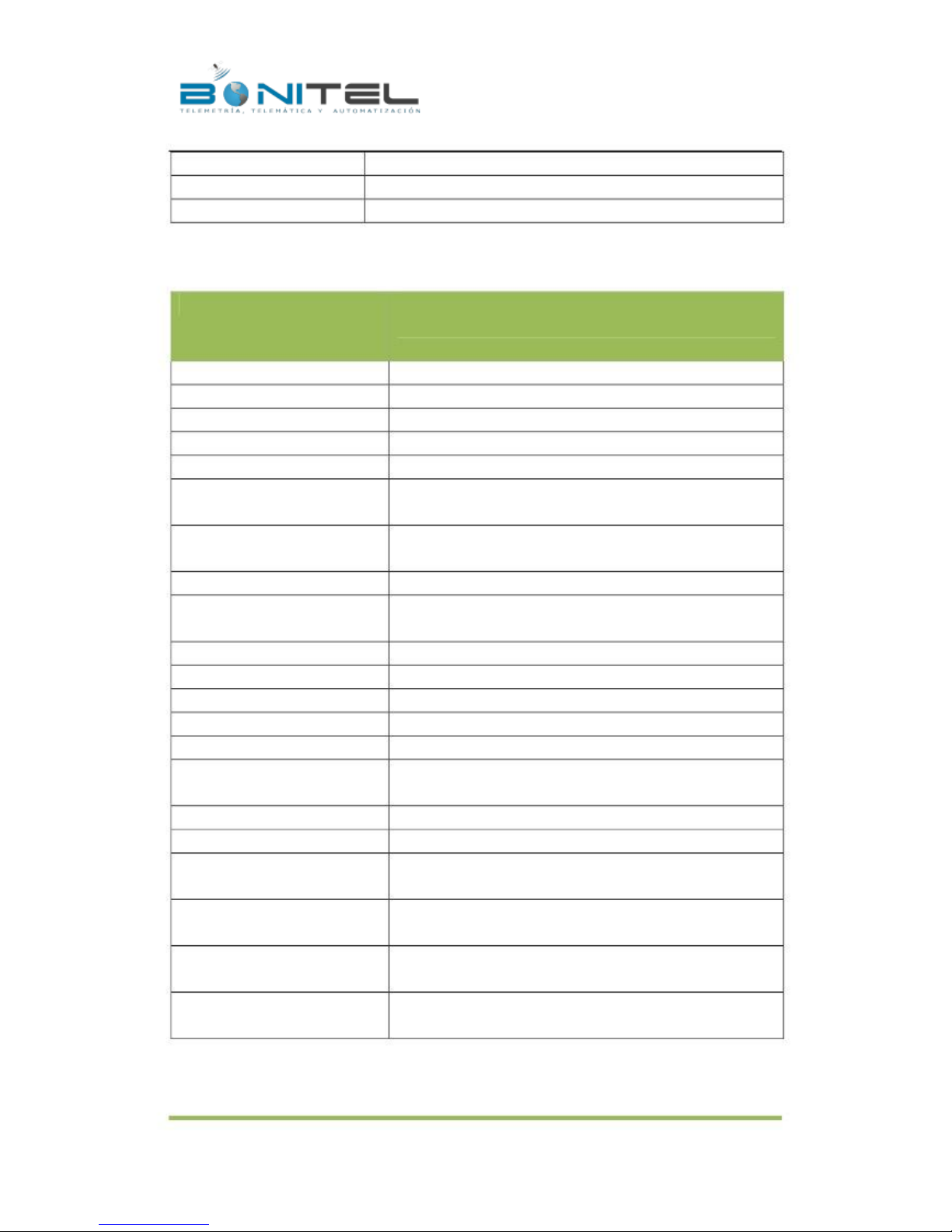
Tracker ID
Read
Write
MVT340’s IMEI. It is the only ID in GPRS packet.
Read current tracker’s settings for above items.
Write above settings to the tracker.
Tick the box for receiving GPRS report.
Event Description:
Event
Description
(If the box is ticked, authorized phone number will get event report
by SMS or calling)
SOS/Input 1 Active
Input 2 Active
SOS/Input1 Inactive
Input 2 Inactive
Low Battery
Low External Power
Speeding
Enter Geo-fence
Exit Geo-fence
External Power On
External Power Off
No GPS Signal
Get GPS Signal
Enter Sleep
Exit Sleep
GPS Antenna Cut
Device Reboot
Heartbeat Report
Heading Change Report
Distance Interval Report
Tow Alarm
Report when input1 (SOS) is active/pressed.
Report when input 2 is active.
Report when input 1 inactive (SOS released).
Report when input 2 inactive.
Report when backup battery’s voltage is below 3.5V.
External power (car battery) is lower than predefined voltage.
You can define voltage in Main Settings.
Report when MVT340 speeds higher than the pre-set value.
Value can be changed on tap III Main Settings
Report when MVT340 enters Geo-fence.
Report when MVT340 exits Geo-fence.
Geo-fence can be changed on tap III Main Settings.
Alarm when external power supply is on or recover.
Alarm when external power supply if off or cut.
Report when MVT340 enters GPS blind area or no GPS signal.
Report when MVT340 exits GPS blind area or get GPS signal.
Report when MVT340 enters sleep mode.
Report when MVT340 exits sleep mode.
Sleep mode can be changed on tap III Main Settings.
Alarm when the GPS antenna is disconnected or cut
Report when MVT340 is rebooting.
Turn on heartbeat report
You can define heartbeat interval on tap III Main Settings.
Auto report when tracker’s direction changes over predefined angle
You can define angle degree on tap III Main Settings.
Track by distance.
Interval can be changed on tap III Main Settings.
Alarm when the tracker trembles for a period of time.
You can define tow time on tap III Main Settings.
For more information about GPRS settings, please refer to MEITRACK SMS/GPRS Protocol.
- 15 -
BONITEL EIRL F: 325 7401 – RPC 987583073 – RPM #970400 - NEXTEL 120*2607
Page 16
File Name:
Project:
Sub Project:
Revision:
MEITRACK MVT340 User Guide
MVT340
User Guide
V2.7
Creator:
Creation Date:
Update Date:
Page:
Confidential:
Cavana Cheung
2010-08-26
2013-01-31
- 16 - of 18
External Documentation
7. Installation
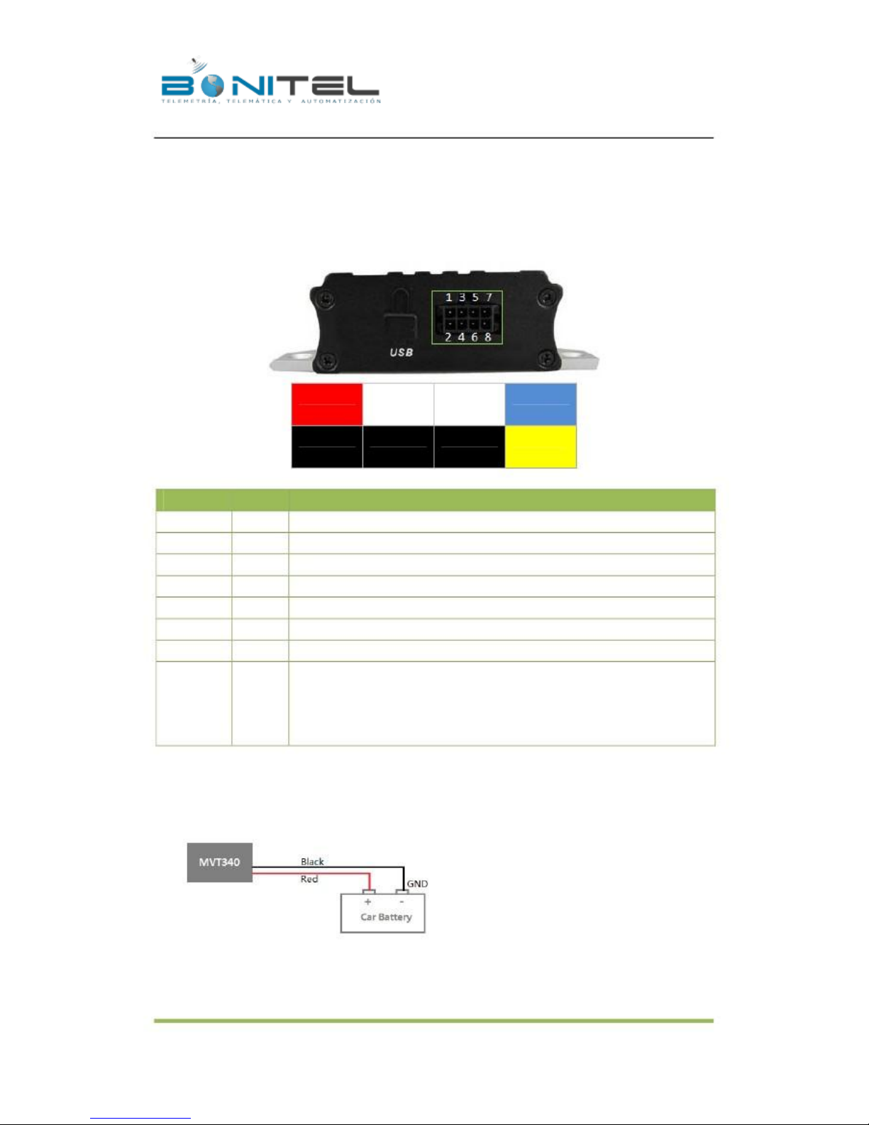
7.1 Install I/O Cable
The I/O cable is a 8-pin cable including power, analog input, negative/positive input and output.
1
POWER(+)
2
GND(-)
PIN Number
1 (POWER)
2 (GND)
3 (SOS)
4 (GND)
5 (IN2)
6 (GND)
7 (AD)
8 (OUT)
Color
Red
Black
White
Black
White
Black
Blue
Yellow
Description
3
INPUT 1
4
GND(-)
5
INPUT 2
6
GND(-)
7
AD INPUT
8
OUTPUT
DC In (power source). Input voltage: 9V~36V. 12V suggested.
Ground
Digital Input 1 (negative triggering)
Ground. Defaulted to be panic button with SOS cable
Digital Input 2 (positive triggering), normally for detecting status of ACC
Ground. It can be used to connect with temperature/fuel sensor etc.
10 Bits Resolution Analog Inputs. 0~6V DC Detection
Output.
Low voltage (0V) when effective and open drain when ineffective.
Output open drain sink voltage (ineffective): 45V max.
Output low voltage sink current (effective): 500mA max.
7.1.1 POWER/GND (PIN1, PIN2)
Connect GND (-Black) and Power (+Red) wires to the battery of vehicle.
- 16 -
BONITEL EIRL F: 325 7401 – RPC 987583073 – RPM #970400 - NEXTEL 120*2607
Page 17
File Name:
Project:
Sub Project:
Revision:
MEITRACK MVT340 User Guide
MVT340
User Guide
V2.7
Creator:
Creation Date:
Update Date:
Page:
Confidential:
Cavana Cheung
2010-08-26
2013-01-31
- 17 - of 18
External Documentation
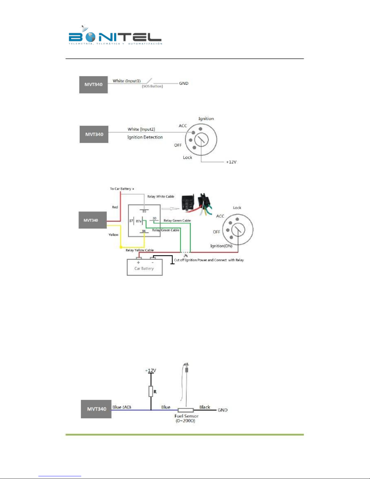
7.1.2 Digital Input (PIN3, Negative Triggering)
7.1.3 Digital Input (PIN5, Positive Triggering)
7.1.4 Output (PIN8)
7.1.5 Analog Input (PIN7)
7.1.5.1 Analog Input Application 1– Detect External Power Voltage
Input range: 0-6V
Voltage Caculating Formula: input voltage=(AD*6)/1024
0x0377=>887(Decimal)=>(887*6)/1024=5.1972V(Voltage)
0x02FB=>763(Decimal)=>(763*6)/1024=4.4707V(Voltage)
7.1.5.2 Analog Input Application 2 – Fuel Detection (percentage of fuel)
- 17 -
BONITEL EIRL F: 325 7401 – RPC 987583073 – RPM #970400 - NEXTEL 120*2607
Page 18
File Name:
Project:
Sub Project:
Revision:
MEITRACK MVT340 User Guide
MVT340
User Guide
V2.7
Creator:
Creation Date:
Update Date:
Page:
Confidential:
Cavana Cheung
2010-08-26
2013-01-31
- 18 - of 18
External Documentation
Note:
Fuel level sensors supplied by our company are resistance-type sensors with output resistance: 0-200Ω
(ohm).
For the circuit shown on above figure, if VCC is 12V, R should be 200Ω (ohm) and if VCC is 24V then R should
be 600Ω (ohm) to make the input range to AD1 or AD2 is 0-6V.
Below formula is for calculating the fuel percentage left for this fuel level sensor:
AD value
1024* 2 – AD value
The value must be converted into decimal, for example, 0x0267 is 615 in decimal.
Percentage Left =
* 100%
7.2 Install GPS/GSM Antenna
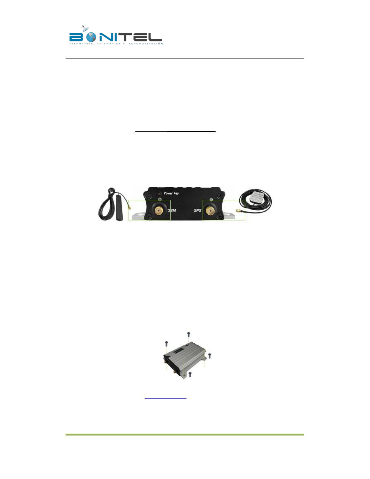
GSM Antenna
so you can hide it in any place of vehicle.
GPS Antenna
Connect the GSM antenna to the SMA connector which is ‘GSM’ text labeled. The GSM antenna is non-directional,
Connect GPS antenna to the GPS connector which is ‘GPS’ labeled. The optimum location for the GPS antenna is
on the roof of the vehicle. The covert and GPS antenna are directional, make sure they are facing up and lying as
flat as possible. Secure them in place with glue or zip ties.
Note: Do not shield or cover the GPS antenna with any objects containing metal.
7.3 Mount the MVT340 unit
If mounting required, there are 4 screw holes on the MVT340, 2 along either side that act as fixing points to the
vehicle.
Please do not hesitate to email us at [email protected] if you have any questions.
- 18 -
BONITEL EIRL F: 325 7401 – RPC 987583073 – RPM #970400 - NEXTEL 120*2607
 Loading...