

Page 1
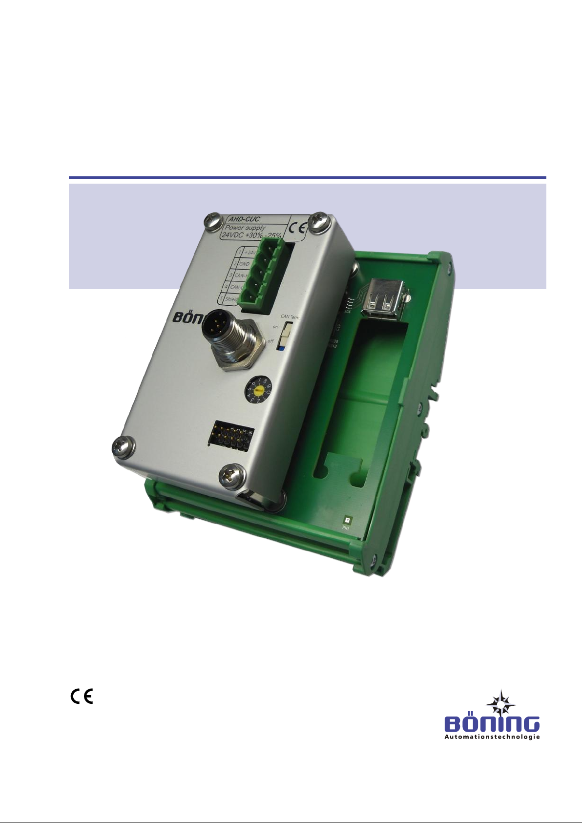
AHD-CUC
Universal CAN Converter
Operating Manual
Read this manual before beginning any work!
Dok-ID: PaB-1174 V3
Page 2

2 V3
© Böning
Automationstechnologie GmbH & Co. KG
Am Steenöver 4
D-27777 Ganderkesee
Tel.: +49 (0) 4221 9475-0
Fax: +49 (0) 4221 9475-21 /-22
Page 3

AHD-CUC Universal CAN Converter
Table of Contents
V3 3
1 General Information ............................................................... 6
1.1 About this Manual .......................................................... 6
1.2 Explanation of Symbols ................................................. 6
1.3 Limitation of Liability ...................................................... 7
1.4 Copyright ........................................................................ 8
1.5 Spare Parts .................................................................... 8
1.6 Warranty Terms ............................................................. 8
1.7 Customer Care............................................................... 8
2 Safety ...................................................................................... 9
2.1 Operator’s Responsibilities ............................................ 9
2.2 Personnel Requirements ............................................. 10
2.2.1 Qualifications ................................................ 10
2.2.2 Unauthorized Persons .................................. 11
2.3 Intended Use................................................................ 11
3 Structure and Function ....................................................... 13
3.1 General Function ......................................................... 13
3.1.1 Supported Operating Systems ..................... 14
3.2 Application Examples for the AHD-CUC ..................... 15
3.2.1 Example 1..................................................... 15
3.2.2 Example 2..................................................... 16
4 Technical Information .......................................................... 17
4.1 Technical Data ............................................................. 17
4.2 Name Plate .................................................................. 18
4.3 Dimensions .................................................................. 19
4.3.1 Device Dimensions ....................................... 19
4.4 Connections ................................................................. 20
4.4.1 Device Connections ..................................... 20
5 Transport, Packaging and Storage .................................... 21
5.1 Transport Safety Instructions ....................................... 21
5.2 Transport Inspection .................................................... 21
5.3 Packaging .................................................................... 21
6 Installation and Initial Startup ............................................. 23
6.1 Safety ........................................................................... 23
6.2 Installation .................................................................... 24
6.3 Initial Startup ................................................................ 26
7 Operation .............................................................................. 27
7.1 Configuration................................................................ 27
7.2 Display Sources Table ................................................. 27
Page 4

AHD-CUC Universal CAN Converter
Table of Contents
4 V3
7.3 Keyboard Command Tables ........................................28
7.4 Mouse Movements .......................................................28
7.5 Special Conditions .......................................................29
7.5.1 Hidden Mouse Pointer ..................................29
7.5.2 Competing Mouse Movements .....................29
8 Maintenance ..........................................................................30
9 Errors .....................................................................................31
9.1 Safety ...........................................................................31
9.2 Error Correction ............................................................32
10 Disassembly .........................................................................33
10.1 Safety 33
10.2 Disassembly .................................................................33
10.3 Disposal 34
11 Index ......................................................................................35
Page 5
AHD-CUC Universal CAN Converter
General Information
V3 5
Date
Version
Reason for Change
Page
Author
04/23/2012
AHD-CUC-DOK_en_V1_20120423
New creation of operation manual
n.a.
Pasuki, Bahram
(PaB)
10/26/2012
AHD-CUC-DOK_EN_V2_20121026
Corrections
13;
14;
26;
28
Pasuki, Bahram
(PaB)
11/27/2012
AHD-CUC-DOK_EN_V3_20121127
Information “Supported Operating
Systems” added
(Bug Tracker Report #1780)
14
Pasuki, Bahram
(PaB)
Change History
for Operation Manual AHD-CUC
Page 6

AHD-CUC Universal CAN Converter
General Information
6 V3
Warnings
In this manual, warnings are marked by symbols. The warnings are
introduced by signal words indicating the degree of danger.
It is important to heed these warnings and act with caution to
avoid accidents, personal injury and equipment damage!
DANGER!
… indicates an imminently hazardous situation that
can result in death or severe injury, if not
avoided.
WARNING!
… indicates a potentially hazardous situation which
can result in death or severe injury, if not
avoided.
1 General Information
1.1 About this Manual
1.2 Explanation of Symbols
Read this operation manual carefully before beginning any
work! It is part of the product and must be kept in the prod-
uct’s immediate vicinity, so that it is always available to the
personnel.
Include this manual when passing the product on to third par-
ties.
This operation manual provides important product handling information. On the following pages, this manual describes the Universal CAN Converter AHD-CUC.
This manual includes specific instructions, in case additional, more
detailed documentation is available for individual components.
Adhering to all product safety and handling instructions for the
product and all connected components is a prerequisite for safe
operation.
In addition, the local accident prevention and general safety rules
for the device’s area of operation must be observed.
The illustrations in this manual are intended to demonstrate the
contents more clearly. They are not necessarily drawn to scale and
can vary from the actual product in minor details.
This operation manual must be viewed exclusively as a complete
unit. It is not permitted to use excerpts from this manual as standalone documentation without referring to the entire document.
Page 7

AHD-CUC Universal CAN Converter
General Information
V3 7
CAUTION!
… indicates a potentially hazardous situation that
can result in minor or light injury, if not avoided.
CAUTION!
… indicates a potentially hazardous situation that
can result in equipment damage, if not avoided.
Tips and Recommendations
TIP!
… indicates useful tips and recommendations as
well as information for efficient and error-free operation.
1.3 Limitation of Liability
All information and instructions in this manual have been compiled
in consideration of current norms and regulations, the state of
technology, and our knowledge and experience of many years.
The manufacturer is not responsible for damages due to:
Noncompliance with the instructions in this manual
Unintended use
Employment of untrained personnel
Unauthorized modifications
Technical modifications
Use of unauthorized spare parts
The actual scope of delivery can vary from the explanations and illustrations in this manual in case of customized models, special
ordering options or the latest technical improvements.
In addition, the agreed upon obligations in the delivery contract, the
general terms and conditions, the manufacturer’s delivery terms
and the legal regulations current at the contract signing are in
force.
We reserve the right to make changes to improve the device’s service properties and to further develop the product.
Page 8
AHD-CUC Universal CAN Converter
General Information
8 V3
TIP!
The information, texts, drawings, illustrations, and
other representations in this manual are protected
by copyright laws and are subject to industrial
property rights. Any misuse is subject to prosecution.
WARNING!
Risk of injury from incorrect spare parts!
Incorrect or defective spare parts can cause damages, malfunctions or complete failure and jeopardize the vessel’s safety.
Therefore:
– Only use the manufacturer’s original spare
parts.
1.4 Copyright
1.5 Spare Parts
This operation manual is a confidential document. It is intended
solely for those persons working with the product. It is not permitted to hand this manual over to third parties without the manufacturer’s prior written permission.
It is not permitted to duplicate this manual in any type or form –
even in excerpts – or use and/or communicate its contents without
the manufacturer’s written permission. Contraventions are liable to
compensation. We reserve other rights.
Please order spare parts from a contracted reseller or directly from
the manufacturer. Refer to page 2 for the address.
1.6 Warranty Terms
The warranty terms can be found in the General Terms and Conditions (GTC) of the manufacturer’s sales documents.
1.7 Customer Care
Our customer service department is available to assist you with
technical information.
Information concerning the corresponding customer contact is always accessible via telephone, fax, e-mail, or the Internet. Please
refer to page 2 for the manufacturer’s address.
In addition, our staff is always interested in new information and
experiences resulting from the use of the product which can be
used to further improve our products.
Page 9

AHD-CUC Universal CAN Converter
Safety
V3 9
2 Safety
This chapter provides an overview of all important safety aspects
for optimal protection of the personnel as well as safe and errorfree operation.
Noncompliance with the handling and safety instructions listed in
2.1 Operator’s Responsibilities
this manual can cause significant hazards.
This product is intended for commercial use. Therefore, its operation is subject to legal workplace safety regulations.
In addition to the workplace safety instructions in this manual, the
current safety, accident prevention, and environmental protection
regulations for the product’s place of use must be observed. Especially:
The operator must stay abreast of the current workplace safety
During the product’s entire period of operation, the operator
The operator must clearly regulate and define areas of respon-
The operator must ensure that all employees handling the
In addition, he must train the personnel in regular intervals and
Furthermore, the operator is responsible for always keeping the
product in perfect working condition.
regulations and determine through a risk assessment any additional hazards resulting from the special working conditions of
the product’s place of use. He must implement these in the form
of operating instructions for the product’s use.
must verify that his operating instructions are in compliance with
current regulations and revise them, if necessary.
sibility for installation, operation, maintenance, and cleaning.
product have read and understood this manual.
inform them about any dangers.
Page 10

AHD-CUC Universal CAN Converter
Safety
10 V3
WARNING!
Risk of injury from insufficient qualifications!
Improper use can lead to significant personal injury
and equipment damage.
Therefore:
– Only allow qualified personnel to perform any
work.
2.2 Personnel Requirements
2.2.1 Qualifications
This manual lists the following qualifications for various areas of
activity.
Trained Person
has been trained by the operator through an orientation for the
assigned tasks and has been informed about possible hazards
from improper execution.
Specialist
is able to execute the assigned tasks and recognize and avoid
potential hazards independently due to formal training, knowledge and experience, as well as knowledge of the situational
norms and regulations
Electrician
is able to work on electrical systems and recognize and avoid
potential hazards independently due to formal training, knowledge and experience, as well as knowledge of the situational
norms and regulations.
The electrician is trained for the specific work site in which he is
active and knows the relevant norms and regulations.
Only those persons who can be expected to do their work reliably
are permitted as personnel. Persons, whose responsiveness is diminished by e.g. drugs, alcohol, or medication, are not permitted.
Observe the local age and profession specific regulations when
selecting the personnel.
Page 11

AHD-CUC Universal CAN Converter
Safety
V3 11
WARNING! Danger to unauthorized persons!
Unauthorized persons who do not meet the requirements described in this manual do not know
the occupational hazards.
Therefore:
– Keep unauthorized persons out of the work
area.
– When in doubt, approach persons and remove
them from the work area.
– Interrupt all work as long as unauthorized per-
sons remain in the work area.
External PC systems, whose video sources are connected to
Böning color displays for visualizations, can be controlled with
the operation elements of the Böning display control panels
AHD-DC, AHD-DRM R, and AHD-DRM T via the Universal CAN
Converter AHD-CUC.
WARNING!
Danger from unintended use!
Any use of the product beyond and/or other its intended use can cause hazardous situations.
Therefore:
– Only use the product as intended.
– Strictly adhere to all instructions in this manual.
– In particular, avoid the following unintended use:
– Using a supply voltage other than the one
indicated in this manual
2.2.2 Unauthorized Persons
2.3 Intended Use
The Universal CAN Converter AHD-CUC has been designed and
constructed exclusively for the purpose described in this manual.
Any claims for damages resulting from unintended use are void.
The operator is solely responsible for any damages resulting from
unintended use.
Page 12

AHD-CUC Universal CAN Converter
Safety
12 V3
WARNING!
Danger from improper operation of the product!
Product failure or malfunctions can lead to personal
injury or equipment damage in the overall system.
Therefore:
– Although the product itself is not dangerous, the
effects of failures or malfunctions on the overall
system must be considered.
– Always discontinue using the products when
they develop smoke or abnormal heat.
Page 13

AHD-CUC Universal CAN Converter
Structure and Function
V3 13
3 Structure and Function
3.1 General Function
The Universal Converter AHD-CUC is used for controlling external
PC systems whose outputs are connected for visualizations to
Böning color displays AHD 12xx / AHD 11xx. They are operated
with the operation elements of the Böning display control panels
AHD-DC, AHD-DRM R, and AHD-DRM T.
The AHD-CUC analyzes messages from all AHD-DRM and AHD-
DC units as well as the displays’ responses. When a display has
switched to a defined video source and an AHD-DRM or AHD-DC
unit sends control commands, these commands are converted to
mouse or keyboard commands and transmitted to the connected
PC.
In this case, the AHD-CUC is subject to the same general conditions as the AHD-DRM.
However, it must be kept in mind that a separate AHD-CUC must
be installed for each external PC (for example navigation PCs or
other PC based ship equipment) in the system.
Several external PC systems can be integrated via a single AHDCUC unit.
The configuration software DeviceConfig is used to assign keyboard and mouse commands to the operating panels’ control elements (keys, rotary push drive or trackball). These commands are
transmitted to the external PC via the standard USB interface.
The assignment of control commands is freely configurable and
therefore, it can be adjusted individually to the external PC’s required controls.
The configuration software is also used to determine the Böning
color display interface (DVI, VGA, FBAS) to which the video source
of the external PC is connected.
This configuration enables the automatic activation of the command transmission when selecting the color display’s corresponding signal source.
Up to 10 color displays can be pre-set individually (standard setting: DVI).
The color display and its signal source are selected at the display
(interface) or the display control panels.
The universal converter units AHD-USB as well as all color displays and display control units are connected to the same control
CAN bus (control CAN bus, CAN5-interface – or CAN, in the case
of monitors – of the display).
Page 14

AHD-CUC Universal CAN Converter
Structure and Function
14 V3
TIP!
The Universal CAN Converter AHD-CUC has been
designed for the application on the following operating system:
- WINDOWS® XP (SP 1 and higher)
3.1.1 Supported Operating Systems
The following operating systems are currently not supported yet:
- WINDOWS® 2000
- WINDOWS® 7
- WINDOWS® 8
Further operating systems are currently being tested.
Please contact the manufacturer for information on whether a spe-
cified operating system (for example LINUX) is supported (see
page 2 for address).
Page 15
AHD-CUC Universal CAN Converter
Structure and Function
V3 15
3.2 Application Examples for the AHD-CUC
3.2.1 Example 1
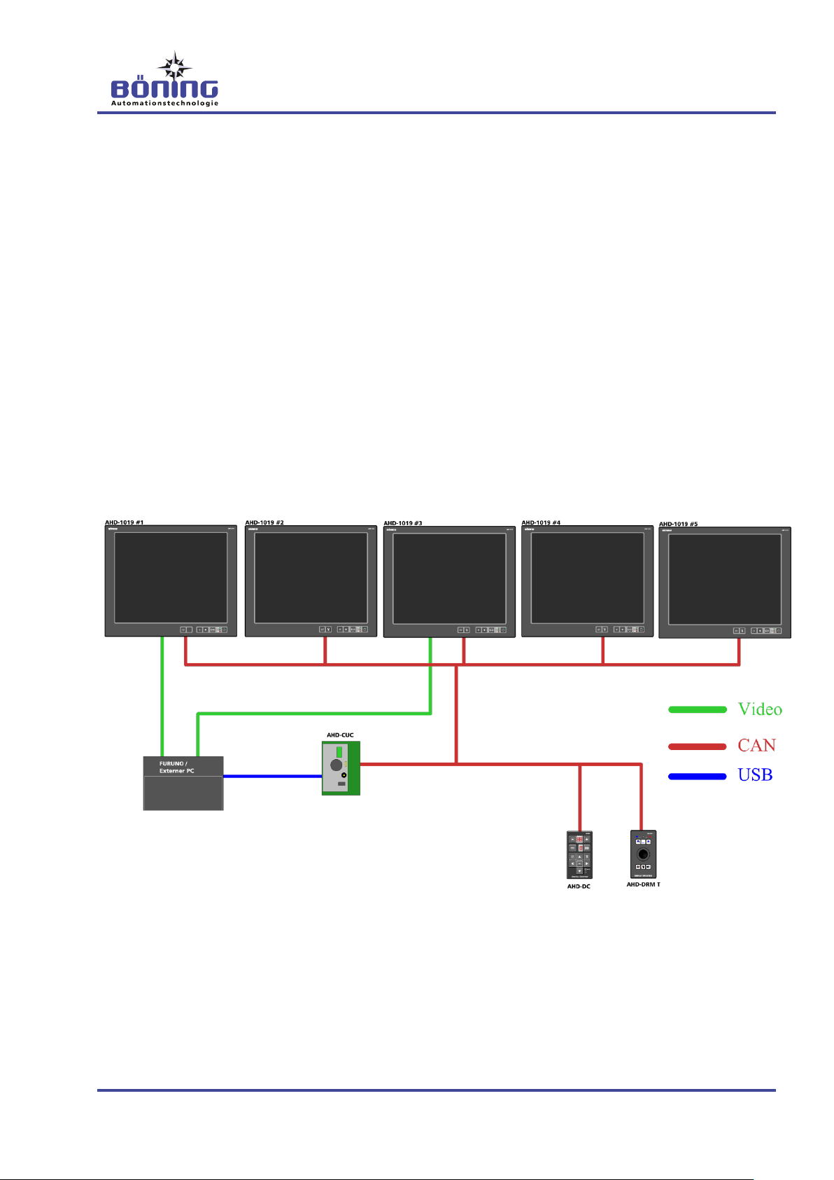
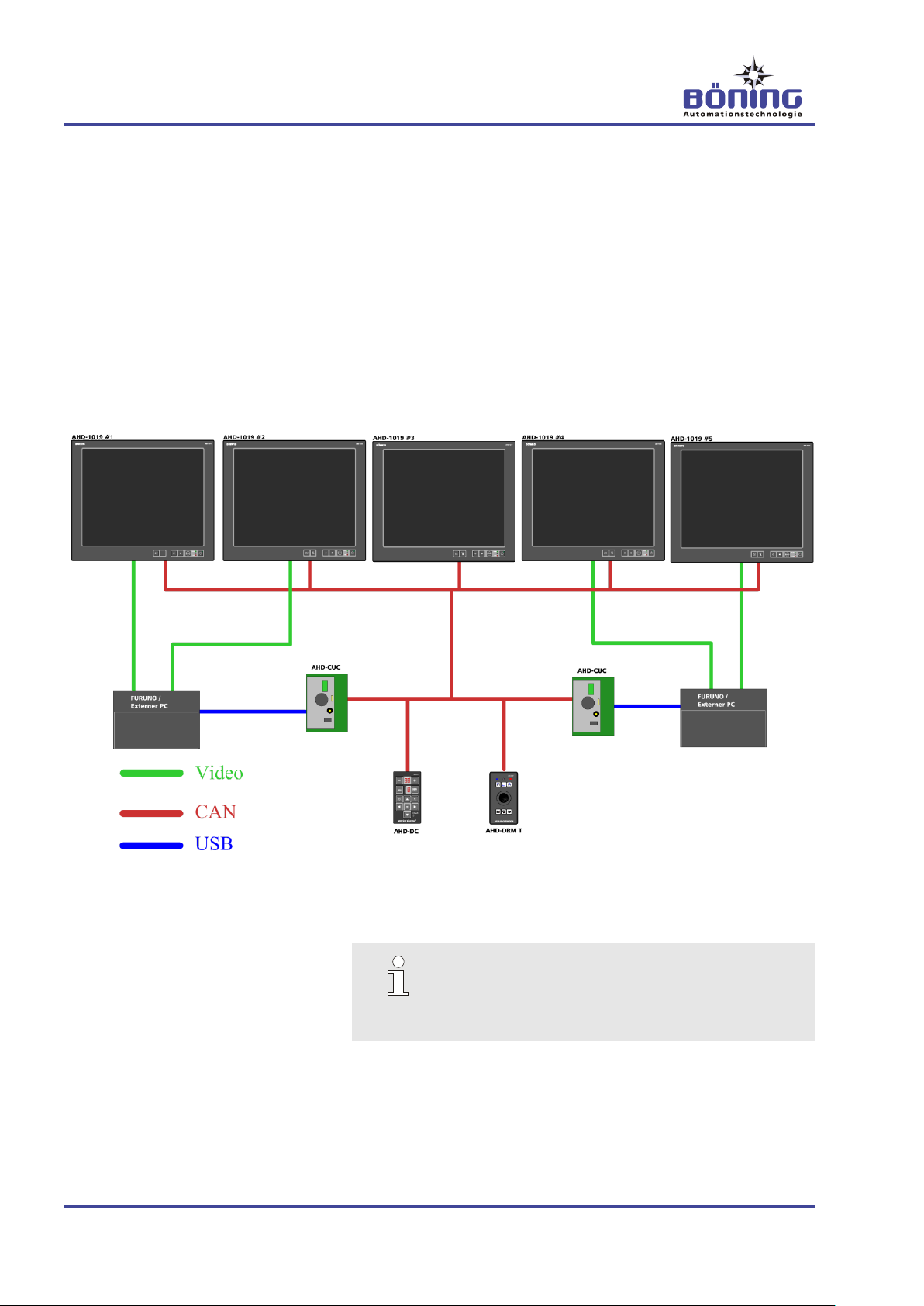
In the following example, five displays (AHD 10xx or higher versions) are installed on a single bridge.
A navigation PC, whose image can be shown on a total of two displays, has been added.
The converter AHD-CUC connects the control CAN bus to the navigation PC, where it identifies itself as a USB mouse and keyboard. Additionally, two control panels (AHD-DC & AHD-DRM T)
are connected to the control CAN bus. These control panels are intended to control the navigation PC as well as the visualization
software on the displays.
For example, if the operator switches from display 2 to display 3
during operation, which is set to the external video source, the
Converter AHD-CUC is activated, which in turn controls the external PC.
Application example 1 for the AHD-CUC
Page 16
AHD-CUC Universal CAN Converter
Structure and Function
16 V3
TIP!
The Universal CAN Converter is currently not com-
patible with PCs using the Windows 7 operating
system.
3.2.2 Example 2
In this example, two separately functioning PCs are connected
next to one another. These are meant to be controllable from two
separate helms (A & B). Since the AHD-CUCs only take a com-
mand’s target monitor ID into account, this can be accomplished
without any problem. If the command contains the ID of a display
which is currently set to an external video source, the received
command is transmitted as a mouse and keyboard command via
USB.
In theory, any number of additional AHD-CUCs can be installed on
a bridge.
Application example 2 for the AHD-CUC
Page 17
AHD-CUC Universal CAN Converter
Technical Information
V3 17
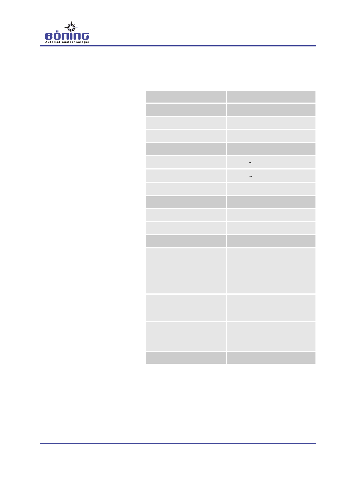
Description
Value/Unit/Type
General Data
Dimensions, W x H x D
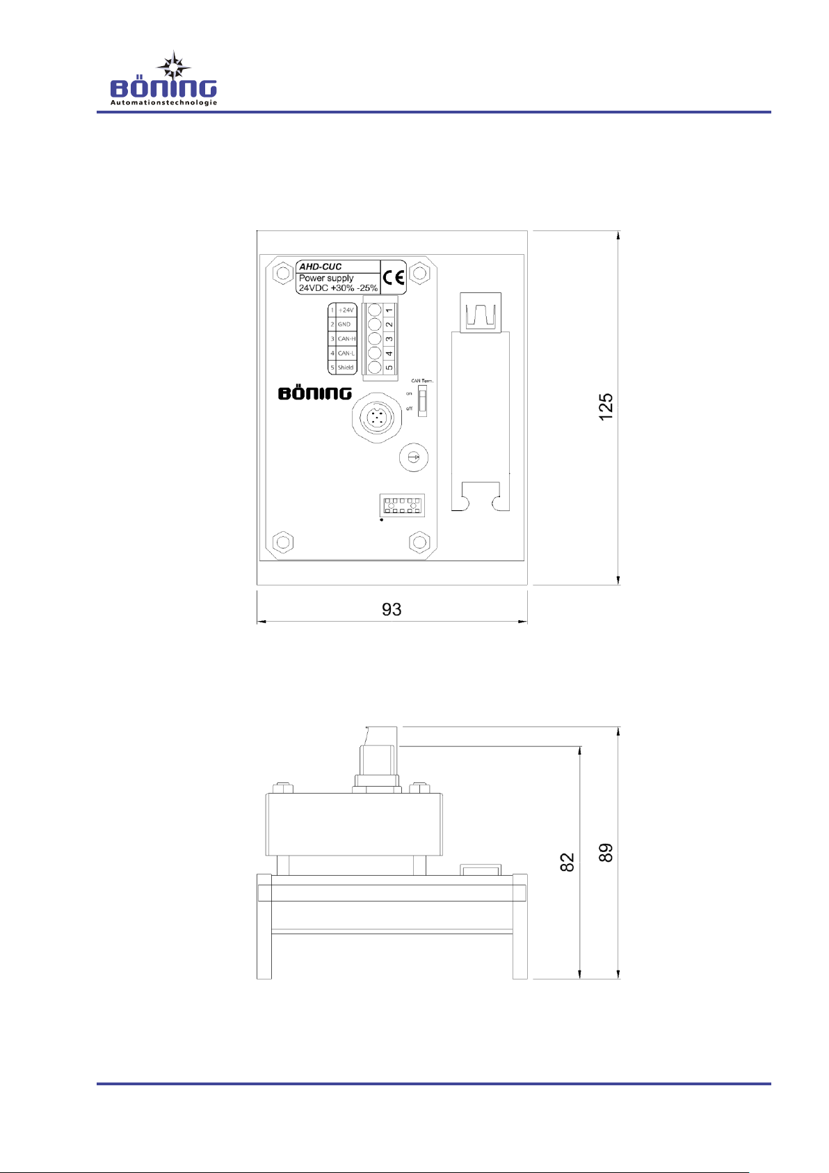
93 x 125 x 89 mm
Weight
appr. 0.25 kg
Environmental Data
Operating Temperature
-25°C… +70°C
Storage Temperature
-30°C… +85°C
Protection Class
IP 20
Electrical Data
Power Supply
24 V DC (+30% -25%)
Power/Current Consumption
appr. 30 mA (24 V DC)
Interfaces
1 x CAN
Data communication with displays and control panel on control CAN bus, switchable
(display CAN Port 5)
1 X USB
Transmission of converted commands for mouse and keyboard
control to the external PC system
5-pin terminal strip
Connection to the 24 V DC power supply
Alternate connection to CAN bus
4 Technical Information
4.1 Technical Data
Page 18

AHD-CUC Universal CAN Converter
Technical Information
18 V3
The data converter AHD-CUC’s name plate is located on the device cover and contains the following information:
Model designation of the unit
Serial number (may be on separate label) and power supply
Manufacturer and CE marking
4.2 Name Plate
Page 19
AHD-CUC Universal CAN Converter
Technical Information
V3 19
4.3 Dimensions
4.3.1 Device Dimensions
Page 20
AHD-CUC Universal CAN Converter
Technical Information
20 V3
TIP!
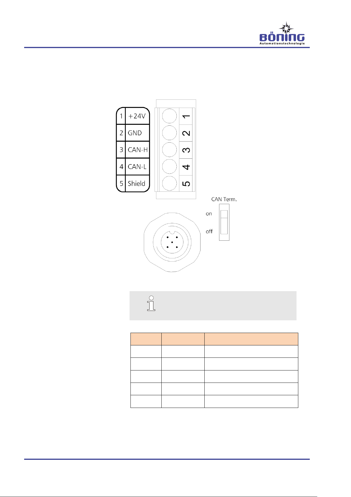
The AHD-CUC’s CAN connection may be
switched on or off when needed.
Terminal
Designation
Explanation
1
+ 24 V
Power supply, positive terminal
2
GND
Power supply, negative terminal
3
CAN-H
CAN-Bus HIGH
4
CAN-L
CAN-Bus LOW
5
Shield
CAN-Bus SHIELD (shielding)
4.4 Connections
4.4.1 Device Connections
Page 21

AHD-CUC Universal CAN Converter
Transport, Packaging and Storage
V3 21
Improper Transport
CAUTION!
Equipment damage from improper transport!
Improper transport can cause significant equipment
damage.
Therefore:
– Use caution when unloading the packages dur-
ing delivery and during on-site transport and
observe the symbols and instructions on the
packaging.
– Remove the packaging only shortly before in-
stallation.
TIP!
Claim any fault as soon as it is noticed. Damage
claims can only be filed within their respective reclamation periods.
About the Packaging
The individual parts are packaged according to the expected
transport conditions. Only environmentally safe materials have
been used for the packaging.
The packaging is intended to protect the individual parts from
transport damages, corrosion and other damages up to the point of
installation. Therefore, the packaging may not be destroyed, and it
may only be removed shortly before installation.
5 Transport, Packaging and Storage
5.1 Transport Safety Instructions
5.2 Transport Inspection
You must inspect the delivery for completeness and damages in
transport immediately upon receipt.
Proceed as follows when noticing external transport damages:
Do not accept delivery, or accept it only with reservation.
Note the scope of the damage on the transport documents or
the deliverer’s bill of lading.
File a claim.
5.3 Packaging
Page 22

AHD-CUC Universal CAN Converter
Transport, Packaging and Storage
22 V3
Handling the Packaging Materials
The packaging materials must be disposed according to current
legal regulations and local ordinances.
CAUTION!
Environmental damages from incorrect disposal!
Packaging materials are valuable raw materials
and can often be reused or meaningfully processed
and recycled.
Therefore:
– Dispose packaging materials in an environmen-
tally safe manner.
– Observe the local disposal regulations. When
necessary, contract a specialist company.
Storage
Store the packages under the following conditions:
Do not store them outdoors.
Store them in a dry, dust free environment.
Do not expose them to aggressive media.
Protect them from sunlight.
Observe the storage temperature (see technical data).
Avoid mechanical shock.
When storing longer than 3 months, regularly inspect the gen-
eral condition of all parts and the packaging. If necessary, re-
fresh or renew the preservative.
TIP!
In some cases, the packages contain instructions
which extend beyond the requirements listed in this
manual. These must be observed accordingly.
Page 23

AHD-CUC Universal CAN Converter
Installation and Initial Startup
V3 23
Personnel
Installation and initial startup may only be performed by special-
ly trained professionals.
Only electricians may work on the electrical system.
Basic Information
Caution!
Risk of injury from improper installation and
initial startup!
Improper installation and initial startup can cause
personal injury and equipment damage.
Therefore:
– Ensure sufficient installation space before be-
ginning any work.
– Handle parts with exposed sharp edges careful-
ly.
– Observe orderliness and cleanliness in the work
area!
– Install parts properly.
6 Installation and Initial Startup
6.1 Safety
Page 24

AHD-CUC Universal CAN Converter
Installation and Initial Startup
24 V3
General Information
CAUTION!
Equipment damage from improper handling
and selection of installation locations!
Installing the products in locations that to not meet
the requirements of the technical specifications
and improper handling can lead to system errors
and equipment damage.
Therefore:
– Observe the products’ technical specifications
when selecting the installation location.
– Only trained personnel may perform the instal-
lation.
– Never install the products in areas that are not
of the required protection type.
– Never install the products in extreme high or
low temperature areas.
– Never install the products on ceilings that can-
not support their weight.
– Never bump or shake the products vigorously.
Installation Requirements
All required connecting cables are of the required version,
equipped with plug connectors according to technical specifica-
tions or project drawings, led to the intended installation loca-
tion, and are properly installed and stripped. Free cables are of
sufficient installation length and are secured against short cir-
cuit and earth fault.
The product is not connected to the supply voltage and switch-
ed off-circuit.
Installation
1. Install the Converter AHD-CUC properly in the intended instal-
lation location according to technical specifications or project
drawings.
2. Wire all of the unit’s inputs and outputs according to technical
drawings.
6.2 Installation
Page 25

AHD-CUC Universal CAN Converter
Installation and Initial Startup
V3 25
CAUTION!
Equipment damage from incorrect cable connections!
Improperly connected cables can cause system
errors and equipment damage.
Therefore:
– Always verify cable and wire designations be-
fore connecting them. Check for secure seating
of the connecting wires in the terminals.
– To avoid short circuits, verify that all wires are
connected in the terminal.
– To not over tighten the terminal clamps.
– When using pluggable terminal strips or plug
connectors, it is imperative to ensure insertion
in the correct socket and secure seating.
3. Test the system for earth/ground fault.
CAUTION!
System failure or malfunction!
During earth/ground fault, incorrect data can be
transmitted and lead to overall system failure or
malfunctions.
Therefore:
– Immediately correct any discovered
earth/ground fault.
Page 26

AHD-CUC Universal CAN Converter
Installation and Initial Startup
26 V3
Startup Requirements
The Converter AHD-CUC has been properly installed and is
equipped will all required connections.
All external devices connected to the Converter AHD-CUC have
also been installed according to technical specifications or
project drawings and are operational.
All required power supplies are available and error-free.
The Converter AHD-CUC and all connected external devices
are not connected to the power supply or have been wired off-
circuit.
1. Establish the 24 V DC power supply according to technical
specifications or project drawings.
2. Establish the power supplies for all external devices connected
to the Converter AHD-CUC according to their corresponding
operating instructions.
3. Test the power supplies.
CAUTION!
Equipment damage from incorrect voltage!
Connecting an incorrect supply voltage can lead to
equipment damage.
Therefore:
– Review all relevant project documents and op-
eration manuals of the devices used and verify
their correct supply voltage and polarity before
connecting them.
4. Switch on the power supply of the Converter AHD-CUC and
all connected external devices from the corresponding circuit
breakers in the power distribution and the device internal
starting devices according to the corresponding operation
manuals.
5. Verify the correct startup sequence according to the following
chapter “Operation.”
6. Log any errors or functional deviations that may occur and
correct errors through proper measures, referring to the errors
described in the chapter titled “Errors.”
7. You may need to review the installed configuration (see Chap-
ter 7.1) and adjust it to the necessary operating conditions.
Log the final configuration for the project documentation.
6.3 Initial Startup
Page 27
AHD-CUC Universal CAN Converter
Operation
V3 27
TIP!
The Converter AHD-CUC must always be confi-
gured separately.
Prior to the configuration, the device must be re-
moved from the CAN bus network and disconnected from the external PC!
For the configuration, the AHD-DeviceConfig must
be connected directly to the AHD-CUC.
Monitor ID
Input ID
(or 0 for not connected)
1
2 (DVI 1)
2
2 (DVI 2)
3
0 (not connected)
4
2 (DVI 1)
5
2 (DVI 2)
6
0 (not connected)
7
0 (not connected)
8
0 (not connected)
9
0 (not connected)
10
0 (not connected)
7 Operation
7.1 Configuration
The AHD-CUC is configured with the Böning software tool AHDDeviceConfig.
There are several configuration tables which can be configured
with AHD-DeviceConfig. These tables determine, to which display
and to which of the display’s video input each PC is connected as
well as which commands are converted to keyboard commands
and which commands are converted to mouse movements.
7.2 Display Sources Table
From this table, the AHD-CUC reads which monitor IDs are relevant to it, since this is where the video signal of its own PC is connected to a certain input.
The following configuration table is intended for the AHD-CUC:
This table can be used to set the Display ID/video signal sources
combination that activates the Converter AHD-CUC.
Page 28

AHD-CUC Universal CAN Converter
Operation
28 V3
TIP!
In most cases, it does not make any sense to
change the number of commands, since all valid
commands already are in the Commands_Count
table.
7.3 Keyboard Command Tables
A (nearly) unlimited number of commands can be set up for translation into keyboard commands.
The number of commands to be analyzed is set in the Commands_Count table. Based on this information, the Commands table is built with a corresponding number of lines. In this table, the
corresponding keyboard code for each command within the AHDDC control bus protocol can be set on the simulated USB keyboard. If fewer or more commands are required, these changes
can also be adjusted via the Commands_Count table.
7.4 Mouse Movements
Since the commands for mouse movements on the CAN bus are
different from key commands, they must be analyzed differently.
Mouse movements always contain two parameters for two axes to
enable continuous, diagonal movements. These movement commands can be configured in an additional table with up to five entries.
Thus, all commands in this table are analyzed as mouse movement commands, not as key presses.
If a command occurs in the keyboard command table as well as in
the mouse command table, the mouse movement is given higher
priority, and the key press is ignored.
Page 29

AHD-CUC Universal CAN Converter
Operation
V3 29
7.5 Special Conditions
7.5.1 Hidden Mouse Pointer
The navigation PC can distribute a split desktop image via two video outputs, thus doubling the viewing area.
If, in this setting, only one display is switched to the navigation PC,
but the mouse pointer is located in the area of the other display,
the pointer is not visible.
In this case, the user must:
- change the navigation PC’s visualization settings (reduce to
one display) or
- return the pointer back to the visible viewing area with corresponding mouse movements or
- activate both displays assigned to the navigation PC or switch
the signal on both displays to the external source.
7.5.2 Competing Mouse Movements
If more than one operation panel (AHD-DC & AHD-DRM) is simultaneously active on a display with PC display, the mouse pointer
behaves as it would on a regular PC with more than one mouse.
This means that the mouse movements amplify one another and,
in the case of opposite movements, cancel one another partially or
wholly.
Page 30
AHD-CUC Universal CAN Converter
Maintenance
30 V3
TIP!
Generally, the Converter AHD-CUC is maintenance
free. Maintenance of the units is limited merely to
external cleansing and inspection.
Only use solvent-free, nonabrasive detergents for
cleaning.
CAUTION!
Risk of injury from dangerous voltages and
other hazards
Opening covers can expose you to dangerous voltages or other hazards.
Therefore:
– Never perform device repairs yourself.
– Do not remove the covers for maintenance or
inspection.
– In case of product malfunctions, contact the
manufacturer or an authorized representative.
8 Maintenance
Page 31
AHD-CUC Universal CAN Converter
Errors
V3 31
Personnel
Some work may only be performed by specially trained profes-
sionals or the manufacturer. This is indicated in the description
of the individual errors.
As a rule, only electricians may work on the electrical system.
Basic Information
CAUTION!
Risk of injury from dangerous voltages or other
hazards
Opening the covers can expose you to dangerous
voltages or other hazards.
Therefore:
– Never perform device repairs yourself.
– Do not remove the covers for maintenance.
WARNING!
Risk of injury from improper error correction!
Improper error correction can cause severe personal injury or equipment damage.
Therefore:
– Only the manufacturer or authorized personnel
may repair the device.
– Ensure sufficient installation space before be-
ginning any work.
– Observe orderliness and cleanliness in the work
area! Parts and tools that are loosely stacked or
lying about are accident sources.
– Observe correct installation procedures when
parts have been uninstalled. Reinstall all mounting elements and observe torque limits.
9 Errors
9.1 Safety
The following table describes errors that can occur when operating
the Converter AHD-CUC, including information about cause, error
recognition, and error correction.
Page 32

AHD-CUC Universal CAN Converter
Errors
32 V3
In Case of Errors
As a rule:
1. Determine the cause of the error.
2. Immediately inform a responsible party on-site.
3. Depending on the error type, have an authorized specialist
correct it, or correct it on your own.
4. Correct the error by replacing or repairing the defective parts
(e.g. cables, plugs, etc.).
5. If the error cannot be determined through the error table, a
device defect cannot be excluded. For repairs, send the device
to the manufacturer’s address or to an authorized specialist
company.
Error
Possible Cause
Diagnosis/Error Correction
The external PC cannot be
controlled.
AHD-CUC power supply interrupted
Test power supply
Test wires and connections
Configuration missing or incorrect
Check the configuration and transfer a
valid configuration to the AHD-CUC, if
necessary
PC operating system is not
supported (Windows 7)
Use a PC with a supported operating
system
CAN bus failure
Check the CAN bus wires and connections on the AHD-CUC as well as those
on the other connected devices and control panels.
Device defect
If all measures for error correction fail, the
device is defective. Consequently, it must
be uninstalled and returned to the manufacturer for diagnosis.
Seemingly random behavior in
the monitoring system; may
autonomously reset the video
source to the monitoring display.
The monitoring software incorrectly analyzes remote commands in a parallel manner.
This cannot be corrected by the user.
Please contact the manufacturer.
9.2 Error Correction
Page 33

AHD-CUC Universal CAN Converter
Disassembly
V3 33
Personnel
Only a specially trained professional may perform the disas-
sembly.
Only electricians may work on the electric system.
Basic Information
Caution!
Risk of injury from improper disassembly!
Stored residual energies, edged parts, points and
corners on and inside the device or the required
tools can cause injury.
Therefore:
– Ensure sufficient installation space before be-
ginning any work.
– Use caution when handling parts with exposed
sharp edges.
– Observe orderliness and cleanliness in the work
area! Parts and tools that are loosely stacked or
lying about are accident sources.
– Uninstall parts properly.
– When in doubt, consult the manufacturer.
10 Disassembly
10.1 Safety
After the device has reached its end of life, it must be disassembled and disposed in an environmentally safe manner.
10.2 Disassembly
Before beginning disassembly: disconnect the device from the
power supply and secure it against reconnection
Disconnect the cable connections and mark them, if necessary.
Secure free wire ends against short circuit and earth/ground
fault.
Loosen the device mountings.
Uninstall the device through proper measures.
Clean and disassemble the device for selection according to
workplace safety and environmental protection regulations.
Page 34

AHD-CUC Universal CAN Converter
Disassembly
34 V3
In the absence of a return or disposal agreement, recycle the disassembled components:
Scrap metals.
Recycle plastic components.
Dispose the other components according to their material prop-
erties.
CAUTION!
Environmental damages from improper disposal!
Electrical scraps, electronic components, lubricants, and other auxiliary materials are subject to
hazardous waste regulations and may only be disposed by licensed specialist companies!
10.3 Disposal
Your local authorities or specialized disposal companies can provide you with information about environmentally safe disposal.
Page 35

AHD-CUC Universal CAN Converter
Index
V3 35
11 Index
A
About this Manual ................................................. 6
Application Examples ......................................... 15
C
Copyright .............................................................. 8
Customer Care ..................................................... 8
D
Device
Connections .................................................... 20
Dimensions ..................................................... 19
Disassembly ....................................................... 33
Display Sources Table ........................................ 27
Disposal .............................................................. 34
E
Error Correction .................................................. 32
Errors .................................................................. 31
Explanation of Symbols ........................................ 6
G
General Function ................................................ 13
I
Initial Startup ....................................................... 26
Installation........................................................... 24
Intended Use ...................................................... 11
K
Keyboard Command Tables ............................... 28
L
Limitation of Liability ............................................. 7
M
Maintenance ....................................................... 30
Mouse Movements ............................................. 28
N
Name Plate ......................................................... 18
O
Operation ............................................................27
Operator’s Responsibilities ................................... 9
P
Packaging ...........................................................21
Personnel
Disassembly ....................................................33
Electrician ........................................................10
Errors ...............................................................31
Initial Startup ...................................................23
Installation .......................................................23
Requirements ..................................................10
Specialist .........................................................10
Trained Person ................................................10
S
Safety .................................................................... 9
Spare Parts ........................................................... 8
Special Conditions
Competing Mouse Movements .......................29
Hidden Mouse Pointer .....................................29
Storage ...............................................................21
Structure and Function .......................................13
T
Technical Data ....................................................17
Transport.............................................................21
Transport Inspection ...........................................21
U
Unauthorized Persons ........................................11
W
Warranty Terms .................................................... 8
Page 36

Devices, System Installation, Monitoring and
Control Technology, Ship Automation
Böning Automationstechnologie GmbH & Co. KG
Am Steenöver 4
D-27777 Ganderkesee
E-Mail: [email protected]
Internet: www.boening.com
Texts and illustrations not binding.
We reserve the right to make changes due to technical improvements.
 Loading...