


30
Redbox User Handbook No 1
DIGITA L AUDIO CONVERTERS - RB-SP1
5
DIGITA L AUDIO CONVERTERS
5 RB-SP1 Digital Splitter & Combiner
Introduction
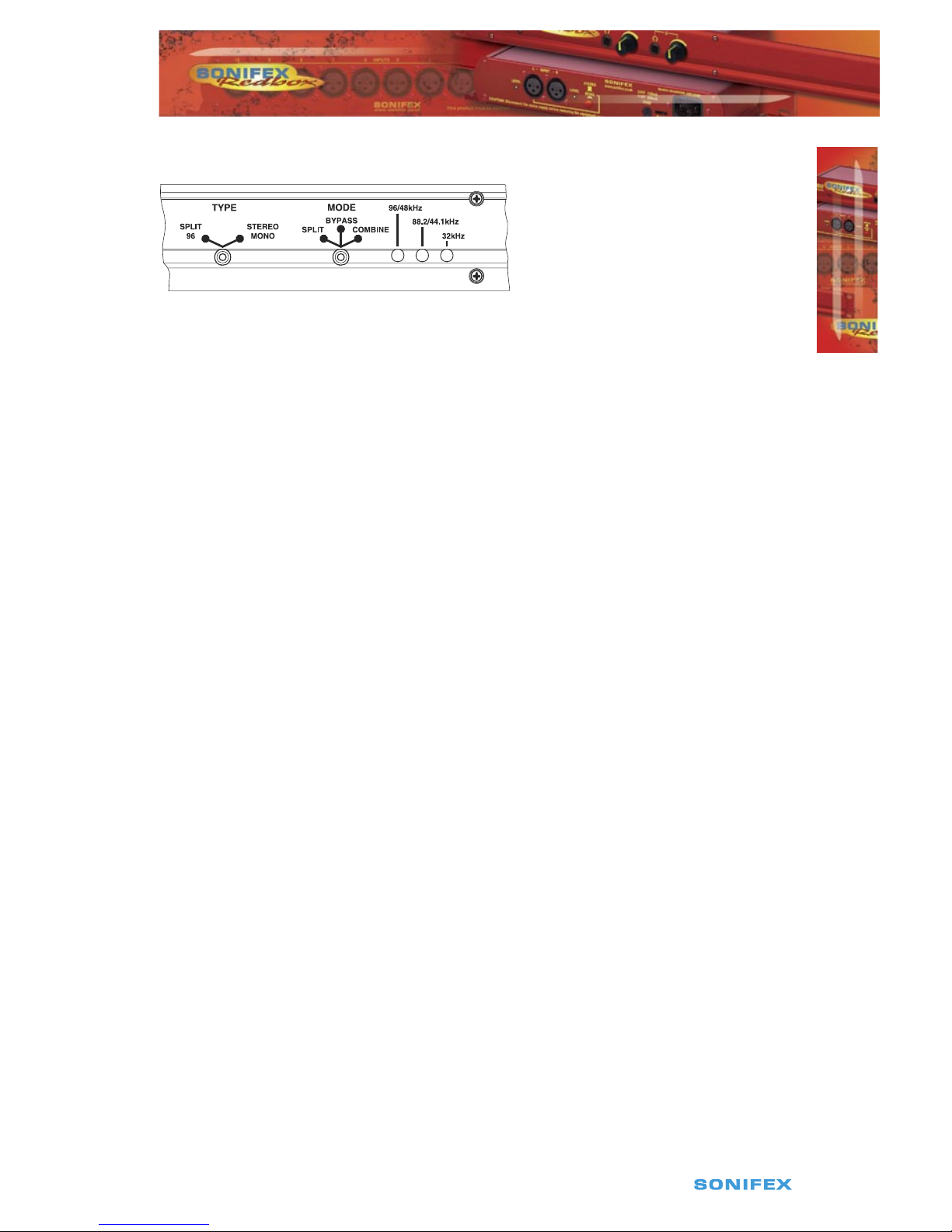
Fig 5-1: RB-SP1 Front Panel
The RB-SP1 Digital Splitter & Combiner is used to interface various double sampling pieces
of equipment. Some older equipment uses 2 AES/EBU connectors for double sampling with
each connector carrying an audio signal at a normal frame rate, whilst other equipment
has a single connector using twice the frame rate. The RB-SP1 can interface between them,
either combining the signals from 2 XLR’s into 1, or splitting the signal from 1 XLR into 2.
The RB-SP1 can also be used for interfacing stereo and mono signals to digital mixing desks
by splitting the left and right signals of a stereo XLR to two separate XLR’s, and vice versa by
combining them.
Additionally, a sample rate converter on the second digital input can be used to convert
the sample rate of the secondary input to that of the primary input. The RB-SP1 can handle
sample rates up to 96kHz and sample sizes of 16, 20 and 24 bit.
There are two types of operation : Split 96, and Stereo/Mono. These each have three
different switch modes : Split, Bypass and Combine.
Both inputs and outputs can be selected as either AES/EBU or S/PDIF with the resultant
digital level following the switch selection.
System Block Diagram
Fig 5-2: RB-SP1 System Block Diagram
Digital
Input
Select
Digital
Output
Select
Receiver
Combine & Bypass Mode Only Split Bypass Mode Only
Receiver
& SRC
Router
Transmitter
Transmitter
Digital
Input 1
Digital
Input 2
Digital
Output
1
Digital
Output
2
Redbox User Handbook No 1
31
5
DIGITA L AUDIO CONVERTERS - RB-SP1
DIGITA L AUDIO CONVERTERS
Front Panel Indicators & Controls
Fig 5-3: RB-SP1 Front Panel
Front Panel LED’s
There are four LED indicators situated on the front of the unit. The red LED on the far left of
the front panel is to indicate that power is present on the unit.
The three LED’s grouped together on the right hand side have two roles, see Fig 5-3. The
first is to indicate the synchronisation frequencies of the incoming digital signals, and the
second is to flash when a signal has been lost. These indicators are labelled individually to
show the current sync frequencies.
Type & Mode Switches
The Type and Mode switches are on the front panel – see Fig 5-3. The Type switch sets the
unit into either the Split 96 or Stereo/Mono style of operation. The Mode switch sets the unit
into Split, Bypass or Combine mode.
See Figure 5-4 for diagrammatic explanations of the different types and modes available.
Split 96 – This is a method that allows older equipment to handle 48kHz double sampled
(96kHz) digital signals. To do this, Split 96 uses two digital signals running at 48kHz, where
both sub-frames of a single 48kHz stream are used to carry information about a mono
signal, with the resultant signal of both 48kHz streams being equivalent to a stereo 96kHz
signal. The unit will also perform the same function for 88.2kHz stereo and 44.1kHz double
sampled signals.
• In Split Mode a single stereo 96kHz signal is received into input 1 which is then
output as two separate 48kHz signals. Output 1 will contain just left channel data and
output 2 will contain just right channel data. If the signal from the input disappears
then both Outputs will be muted.
• In Combine Mode two 48kHz double sampled input signals are combined to create a
single 96kHz signal on output one. If either input 1 or 2 are lost then the output will be
muted. In this mode output 2 will always be muted.
Stereo/Mono – This allows a digital stereo signal to be separated into two mono digital
signals and vice-versa.
• In Split Mode a single stereo digital signal is routed to two digital outputs. Output
1 will contain the original left channel data on its left output and a muted signal on

32
Redbox User Handbook No 1
DIGITA L AUDIO CONVERTERS
5
DIGITA L AUDIO CONVERTERS - RB-SP1
its right output. Output 2 will contain the original right data on its left output and a
muted signal on its right output. This mode can be altered by the dipswitch settings,
to a channel swap mode or a dual mono mode. These are described in more detail in
the Rear Panel Controls section below.
• In Combine Mode two mono signals are combined to create a single stereo signal.
Output 1 will contain the input 1 left channel data on its left channel and input 2 left
channel data on its right channel. This mode can be altered by a dipswitch setting, as
with the split mode. Where either the left or right channel data of input 2 is output on
the right channel data of the output. If the two signals are of different sample rates,
a sample rate converter can be switched in place to convert the sample rate of input
channel 2 to that of input channel 1. In the Stereo/Mono Combine mode, output 2 is
always muted.
Bypass Mode – In Bypass mode, input 1 is routed to output 1 and input 2 is routed to
output 2. Input 1 is used as the master clock input. If input 2 is at a different sample rate
to input 1 then input 2 is sample rate converted to match input 1. If the signal from input
2 is lost then output 2 will be muted. However, if the signal from input 1 is lost then both
outputs will be muted and will only return once a signal is present on input 1.
Note that when the unit is operating in Bypass Mode the Type switch is ignored.
Split 96
48kHz double sampled
48kHz double sampled
48kHz double sampled
96kHz
I/P 1
I/P 1
I/P 2
L
R
SRC
L
R
R
R
L
L
O/P 1
O/P 1
O/P 2
R
R
L
L
96kHz
48kHz double sampled
Split
Combine

Redbox User Handbook No 1
33
DIGITA L AUDIO CONVERTERS - RB-SP1
5
DIGITA L AUDIO CONVERTERS
48kHz double sampled
48kHz double sampled
48kHz double sampled
96kHz
I/P 1
I/P 1
I/P 2
L
R
I/P 1
I/P 1
I/P 2
L
R
L
Dipswitch 3
Off
Dipswitch 3
On
Dipswitch
3
On
Dipswitch 1
On
Dipswitch 1OnDipswitch 1
Off
SRC
SRC
Dipswitch 1
Off
Mute
Mute R
R
L
L
R
MuteR
L
X
R
X
X
R
L
R
L
R
R
R
L
L
O/P 1
O/P 1
O/P 2
O/P 1
O/P 1
O/P 2
R
R
L
L
96kHz
48kHz double sampled
A
ny Sample Rate
Sample Rate 1
Sample Rate 2
Sample Rate 1
X = Input Ignored
Split
Combine
Split
Combine
Bypass
Fig 5-4: RB-SP1 Type and Mode Flow Diagrams
Rear Panel Connections and Operation
Fig 5-5: RB-SP1 Rear Panel
AES/EBU
Inputs
Mode Select
Dip Switches
AES/EBU
Outputs
Digital Input &
Output Select
Buttons
S/PDIF
Outputs
S/PDIF
Inputs
48kHz double sampled
48kHz double sampled
48kHz double sampled
96kHz
I/P 1
I/P 1
I/P 2
L
R
I/P 1
I/P 1
I/P 2
L
R
L
Dipswitch 3
Off
Dipswitch 3
On
Dipswitch
3
On
Dipswitch 1
On
Dipswitch 1OnDipswitch 1
Off
SRC
SRC
SRC
Dipswitch 1
Off
Mute
Mute R
R
L
L
R
MuteR
L
X
R
X
X
R
L
R
L
R
R
R
L
L
I/P 1
I/P 2
O/P 1
O/P 1
O/P 2
O/P 1
O/P 1
O/P 2
O/P 1
O/P 2
L
R
L
R
L
R
L
R
R
R
L
L
96kHz
48kHz double sampled
A
ny Sample Rate
Sample Rate 1
Sample Rate 2
Sample Rate 1
Sample Rate 1
Sample Rate 1
X = Input Ignored
Sample Rate 2
Split
Combine
Split
Combine
Stereo/Mono
34
Redbox User Handbook No 1
Inputs and Outputs
AES/EBU Inputs
The digital source XLR 3 pin sockets have an impedance of 110Ω. They have the following
connections and meet the IEC 60968 specification:
Pin 1: Screen
Pin 2: Phase
Pin 3: Non-phase
S/PDIF Inputs
The digital source RCA phono inputs both have an impedance of 75Ω.
AES/EBU Outputs
The digital output XLR 3 pin plugs have an impedance of 110Ω. They have the following
connections and meet the IEC 60968 specification:
Pin 1: Screen
Pin 2: Phase
Pin 3: Non-phase
S/PDIF Outputs
The digital output S/PDIF phono outputs have an impedance of 75Ω.
Rear Panel Controls
Digital Input & Output Select Buttons
These buttons are used to switch the digital connection between the AES/EBU XLR
connector (button out) and the S/PDIF phono connector (button in) for the digital source
and digital output.
Mode Select Dip Switches
RB-SP1 Mode Select Settings
1 ON Input 1 Channel B = Output 2 Channel B in Stereo/Mono Split Mode
1 OFF Input 1 Channel B = Output 2 Channel A in Stereo/Mono Split Mode
2 ON SRC Enabled
2 OFF SRC Disabled
3 ON Dual Mono in Stereo/Mono Split Mode
3 OFF Single Mono in Stereo/Mono Split Mode
4 Reserved
Fig 5-6: RB-SP1 Mode Select Dip Switches
Altering the Stereo/Mono Split/Combine Mode – In Split mode With switch 1 off, channel
A (Left) and B (Right) on the input are transferred to channel A (Left) of outputs 1 and 2
respectively. With switch 1 on, channel A (Left) on the input is transferred to channel A (Left)
on output 1 and channel B (Right) on the input is transferred to channel B (Right) of output
DIGITA L AUDIO CONVERTERS
DIGITA L AUDIO CONVERTERS - RB-SP1
5

Redbox User Handbook No 1
35
DIGITA L AUDIO CONVERTERS - RB-SP1
5
DIGITA L AUDIO CONVERTERS
2. With switch 3 on (switch 1 is ignored), channel A (Left) is transferred to both channels on
output 1 and channel B (Right) on the input is transferred to both channels on output 2.
In Combine mode with switch 1 off, channel A (Left) on input 1 is transferred to channel
A (Left) of output 1, and channel A (Left) on input 2 is transferred to channel B (Right) of
output 1. With switch 1 on channel A (Left) on input 1 is transferred to channel A (Left) of
output 1, and channel B (Right) on input 2 is transferred to channel B (Right) of output 1.
Switching on the Sample Rate Converter - Switch 2 is used to turn the sample rate
converter on, or off and can be used in all modes. When there are two inputs connected
to the unit which are at different sample rates or which need to be synchronised, then the
sample rate converter should be switched on. If it is not, then you may suffer from missed
samples and bit errors affecting the signal output. If the sample rates of the incoming
signals are always going to be the same and are synchronised, then switch the sample rate
converter off, as leaving it on will worsen the output signal (signal jitter will increase).
Technical Specifications RB-SP1
Audio Specifications
Input Impedance: 110Ω ± 20% balanced (AES/EBU)
Input Impedance: 75Ω ±5% unbalanced (S/PDIF)
Output Impedance: 110Ω ± 20% balanced (AES/EBU)
Output Impedance: 75Ω ±5% unbalanced (S/PDIF)
Signal Level 3V/10V peak to peak min/max (AES/EBU)
0.5V ±20% peak to peak (S/PDIF)
Sample Freq Range: 30-100kHz (i.e. including 32kHz, 44.1kHz, 48kHz, 64kHz,
88.2kHz and 96kHz)
Connections
Audio Inputs: 2 x AES/EBU XLR 3 pin female
2 x S/PDIF RCA phono female
(Input button select between AES/EBU and S/PDIF)
Audio Outputs: 2 x AES/EBU XLR 3 pin male
2 x S/PDIF RCA phono female
(Output button selects between AES/EBU and S/PDIF)

36
Redbox User Handbook No 1
Mains Input: Filtered IEC, continuously rated
85-264VAC @ 47-63Hz max 10W
9.5.3. Equipment Type
RB-SP1 Digital splitter & combiner
9.5.4. Physical Specifications
Dimensions (Raw) 48cm (W) x 10.8cm (D) x 4.2cm (H) (1U)
Dimensions (Boxed) 53cm (W) x 20.5cm (D) x 6cm (H)
Weight Nett: 1.6kg Gross: 2.2kg
DIGITA L AU D I O CONVERTERS
DIGITA L AU D I O CONVERTERS - RB - S P 1
5
 Loading...