


Agile
Profibus Communication manual
Frequency inverter 230V / 400V


General Information on the Documentation
CONTENTS
1
General Information on the Documentation.................................................................. 5
1.1 Instruction Manuals ............................................................................................. 5
1.2 Used Pictograms and Signal Words ...................................................................... 6
2 General Safety Instructions and Information on Use .................................................... 7
2.1 General Information ............................................................................................. 7
2.2 Purpose of the Frequency Inverters..................................................................... 7
2.3 Transport and Storage.......................................................................................... 7
2.4 Handling and Installation..................................................................................... 8
2.5 Electrical Installation ........................................................................................... 8
2.6 Information on Use ............................................................................................... 9
2.6.1 Using external products............................................................................................ 9
2.7 Maintenance and Service...................................................................................... 9
2.8 Disposal ................................................................................................................ 9
3 Communication Options............................................................................................... 10
3.1 VPlus PC-Software.............................................................................................. 10
4 Installation of an optional Communication Module ..................................................... 11
4.1 Assembly............................................................................................................. 11
4.2 Disassembly ........................................................................................................ 11
5 Connection ................................................................................................................... 12
6 Commissioning via the Operator Panel........................................................................ 13
6.1 Menu for setting up the Communication............................................................ 13
6.2 Select the Protocol ............................................................................................. 14
6.3 Set the Communication Parameters................................................................... 14
7 Profibus ........................................................................................................................ 15
8 Baud Rate Setting / Line Length.................................................................................. 16
9 Setting the Station Address ......................................................................................... 16
10 LED Indicators .............................................................................................................. 17
11 Status Parameters........................................................................................................ 18
12 Error Behavior .............................................................................................................. 18
13 Setting PPO Type ......................................................................................................... 19
13.1 Configuration Process on the DP Master ............................................................ 20
14 Commands SYNC / FREEZE .......................................................................................... 22
15 Available Objects / Scanning Times............................................................................. 22
16 Handling of the Objects ............................................................................................... 25
16.1 Parameter Access via Communication Channel PKW ......................................... 25
Probus DP V1 Agile 306/2010

General Information on the Documentation
16.1.1
Request Identification ............................................................................................ 26
16.1.2 Response Identification .......................................................................................... 26
16.1.3 Fault Messages...................................................................................................... 26
16.1.4 Parameters, Data Set Selection and Cyclic Writing .................................................... 27
16.1.5 Sequence of Communication................................................................................... 28
16.1.6 Communication Examples....................................................................................... 29
16.2 Parameter Access via the DP-V1 Channel .......................................................... 31
16.2.1 Operation Mode "Standard".................................................................................... 32
16.2.2 Operation Mode "S7 Compatible" ............................................................................ 33
16.3 Process Data Channel ......................................................................................... 34
16.3.1 Data Types of OUT/IN-Objects................................................................................ 34
16.3.2 Profibus Output Sources (OUT-PZD x) ..................................................................... 36
16.3.3 Profibus Input Parameters (IN-PZD x) ..................................................................... 37
16.4 Frequency Conversion PDP Word Inverter Internal Notation.................... 39
16.4.1 PZD1, Control Word / Status Word .......................................................................... 40
16.4.2 Control via Contacts............................................................................................... 41
16.4.3 Control via State Machine ....................................................................................... 43
16.4.4 Control via Remote Contacts................................................................................... 50
16.4.5 PZD2, Reference Value / Actual Value...................................................................... 53
16.5 Actual Value Display of Profibus Data ................................................................ 54
17 Parameter List.............................................................................................................. 57
17.1 Actual Values ...................................................................................................... 57
17.2 Parameters ......................................................................................................... 58
18 Annex ........................................................................................................................... 59
18.1 Warning Messages.............................................................................................. 59
18.2 Fault Messages ................................................................................................... 60
Index .................................................................................................................................. 61
Probus DP V1 Agile 06/20104

General Information on the Documentation
1 General Information on the Documentation
This documentation describes the communication with
Agile
device series frequency inverters using
the Profibus DP V1 protocol. The modular hardware and software structure allows the user-friendly
customization of the frequency inverters. Applications, which demand high functionality and dynamics
can be comfortably implemented.
1.1 Instruction Manuals
For better clarity, the user documentation is structured according to the customer-specific demands
made on the frequency inverter.
Quick Start Guide
The "Quick Start Guide" brief instructions manual describes the basic steps for the mechanical and
electrical installation of the frequency inverter. The guided commissioning supports you with the
selection of the necessary parameters and the software configuration.
Operating Instructions
The Operating Instructions documents the complete functionality of the frequency inverter. The
parameters necessary for specific applications for adaptation to the application and the extensive
additional functions are described in detail.
Application Manual
The application manual supplements the documentation for purposeful installation and commissioning
of the frequency inverter. Information on various subjects connected with the use of the frequency
inverter are described specific to the application.
The documentation und further information can be requested from your local BONFIGLIOLI
representative.
The following instruction manuals are available for the
Agile
Operating Instructions Frequency inverter functionality.
Agile
Quick Start Guide Installation und commissioning. Supplied with the device.
Agile
device series:
Communication Manual Communication via the RS485 Interface on the X21 Connection (RJ45):
Instructions for Modbus and VABus.
Communication via the X12.5 and X12.6 Control Terminals:
Instructions for Systembus and CANopen®
1
.
Communication via the Communication Modules:
CM-232/CM-485: Instructions for Modbus and VABus.
CM-CAN: Instructions for Systembus and CANopen®.
CM-PDPV1: Instructions for Profibus-DP-V1
PLC Application Manual Logical interconnections of digital signals. Functions for analog signals
such as comparisons and mathematical functions. Graphical support for
the programming of functional components.
Service Instructions For service personnel. Service work, monitoring of service intervals and
replacement of ventilators.
This documentation has been produced with the greatest of care and extensively and repeatedly
checked. For reasons of clarity, not all the detailed information on all types of the product and also
not every imaginable case of installation, operation or maintenance has been taken into account. If
you require further information or if specific problems which are not dealt with extensively enough in
the documentation exist, you can request the necessary information from the local BONFIGLIOLI
representative.
1
The CANopen®-Communication products fulfill the specifications of the CiA® (CAN in Automation)
user organization.
Probus DP V1 Agile 506/2010

General Information on the Documentation
We would also point out that the contents of this documentation are not part of a previous or existing
agreement, assurance or legal relationship and are not intended to amend the same. All obligations of
the manufacturer result from the underlying purchase contract, which also contains the complete and
solely valid warranty regulation. These contractual warranty provisions are neither extended nor
limited by the production of this documentation.
The manufacturer reserves the right to correct or amend the contents and the product information as
well as omissions without prior notification and assumes no kind of liability for damage, injuries or
expenditure to be put down to the aforementioned reasons.
1.2 Used Pictograms and Signal Words
The following pictograms and signal words are used in the documentation:
Danger!
Danger refers to an immediate threat. Non-compliance with the precaution described will
result in death, serious injury or material damage.
Warning!
Warning refers to a possible threat. Non-compliance with the warning may result in death,
serious injury or material damage.
Caution!
Caution refers to an immediate hazard. Non-compliance may result in personal or material
damage.
Attention!
Attention and the related text refer to a possible behavior or an undesired condition which can occur
during operation.
Note
Marks information that facilitates handling for you and supplements the corresponding part of the
documentation.
Probus DP V1 Agile 06/20106

General Safety Instructions and Information on Use
2 General Safety Instructions and Information on Use
Warning!
The specifications and instructions contained in the documentation must be complied with
strictly during installation and commissioning. Before starting the relevant activity, read the
documentation carefully and comply with the safety instructions. The term "Qualified Staff"
refers to anybody who is familiar with the installation, assembly, commissioning and
operation of the frequency inverter and has the proper qualification for the job.
2.1 General Information
Warning!
The DC-link circuit of the frequency inverter is charged during operation, i.e. there is
always the risk of contact with high voltage. Frequency inverters are used for driving
moving parts and they may become hot at the surface during operation.
Any unauthorized removal of the necessary covers, improper use, wrong installation or
operation may result in serious injuries or material damage.
In order to avoid such injuries or damage, only qualified technical staff may carry out the
transport, installation, commissioning, setup or maintenance work required. The standards
EN 50178, IEC 60364 (Cenelec HD 384 or DIN VDE 0100), IEC 60664-1 (Cenelec HD 625
or VDE 0110-1) as well as the applicable national regulations must be complied with. The
term „Qualified Staff“ refers to anybody who is familiar with the installation, assembly,
commissioning and operation of the frequency inverter as well as the possible hazards and
has the proper qualification for the job.
Persons who are not familiar with the operation of the frequency inverter and children
must not have access to the device.
2.2 Purpose of the Frequency Inverters
Warning!
The frequency inverters are electrical drive components intended for installation in
industrial plants or machines. Commissioning and start of operation is not allowed until it
has been verified that the machine meets the requirements of the EC Machinery Directive
2006/42/EEC and EN 60204. In accordance with the CE marking requirements, the
frequency inverters comply with the Low Voltage Directive 2006/95/EC as well as
EN 61800-5-1. The user shall be responsible for making sure that the requirements of the
EMC Directive 2004/108/EEC are met. Frequency inverters are only available at specialized
dealers and are exclusively intended for professional use as per EN 61000-3-2.
Purposes other than intended may result in the exclusion of warranty.
The frequency inverters are also marked with the UL label according to UL508c, which
proves that they also meet the requirements of the CSA Standard C22.2-No. 14-95.
The technical data, connection specifications and information on ambient conditions are
indicated on the name plate and in the documentation and must be complied with in any
case. Anyone involved in any kind of work at the device must have read the instructions
carefully and understood them before starting the work.
2.3 Transport and Storage
The frequency inverters must be transported and stored in an appropriate way. During transport and
storage the devices must remain in their original packaging.
The units may only be stored in dry rooms which are protected against dust and moisture. The units
may be exposed to little temperature deviations only. Observe the conditions according to EN 607213-1 for storage, EN 60721-3-2 for transport and the marking on the packaging.
The duration of storage without connection to the permissible nominal voltage may not exceed one
year.
Probus DP V1 Agile 706/2010

General Safety Instructions and Information on Use
2.4 Handling and Installation
Warning!
Damaged or destroyed components must not be put into operation because they may be a
health hazard.
The frequency inverters are to be used in accordance with the documentation as well as the
applicable directives and standards.
They must be handled carefully and protected against mechanical stress.
Do not bend any components or change the isolating distances.
Do not touch electronic components or contacts. The devices are equipped with components which
are sensitive to electrostatic energy and can be damaged if handled improperly. Any use of damaged
or destroyed components shall be considered as a non-compliance with the applicable standards.
Removal of seal marks may cause restrictions on warranty.
Do not remove any warning signs from the device.
2.5 Electrical Installation
Warning!
Before any assembly or connection work, discharge the frequency inverter. Verify that the
frequency inverter is discharged.
Do not touch the terminals because the capacitors may still be charged.
Comply with the information given in the operating instructions and on the frequency
inverter label.
Comply with the rules for working on electrical installations.
Rules for working on electrical installation:
− Separate completely (isolate the installation from all possible sources of electrical power.
− Fix (protect against reconnection). Reconnection must be carried out by suitably qualified persons.
− Verify there is no electrical power. Verify that there is no voltage against earth on the plant
component by measuring with measurement device or voltage tester.
− Ground and connect in a short circuit. Connect earth conductors.
− Protect against nearby power sources and delimit the working zone.
1)
In plants with a nominal power up to 1 kV deviation from description may be possible.
When working at the frequency inverters, comply with the relevant accident prevention regulations,
the applicable standards, standards governing work on systems with dangerous voltages (e.g. EN
50178), directives for electrical and mechanical equipment erection and other national directives.
Comply with the electrical installation instructions given in the documentation as well as the relevant
directives.
Responsibility for compliance with and examination of the limit values of the EMC product norm EN
61800-3 for variable-speed electrical drive mechanisms is with the manu-facturer of the industrial
plant or machine. The documentation contains information on EMC-conforming installation.
The cables connected to the frequency inverters may not be subjected to high-voltage insulation tests
unless appropriate circuitry measures are taken before.
Do not connect any capacitive loads.
Probus DP V1 Agile 06/20108

General Safety Instructions and Information on Use
2.6 Information on Use
Warning!
The frequency inverter may be connected to power supply every 60 s. This must be
considered when operating a mains contactor in jog operation mode. For commissioning or
after an emergency stop, a non-recurrent, direct restart is permissible.
After a failure and restoration of the power supply, the motor may start unexpectedly if the
auto start function is activated.
If staff is endangered, a restart of the motor must be prevented by means of external
circuitry.
Before commissioning and the start of the operation, make sure to fix all covers and check
the terminals. Check the additional monitoring and protective devices according to EN
60204 and applicable the safety directives (e.g. Working Machines Act, Accident Prevention
Directives etc.).
No connection work may be performed, while the system is in operation.
2.6.1 Using external products
Please note, that Bonfiglioli Vectron does not take any responsibility for the compatibility of external
products (e.g. motors, cables, filters, etc.).
To ensure the best system compatibility, Bonfiglioli Vectron offers components which simplify
commissioning and provide the best tuning with each other during operation.
Using the device in combination with external products is carried out at your own risk.
2.7 Maintenance and Service
Warning!
Unauthorized opening and improper interventions can lead to personal injury or material
damage. Repairs on the frequency inverters may only be carried out by the manu-facturer
or persons authorized by the manufacturer.
Check protective equipment regularly.
Any repair work must be carried out by qualified electricians.
2.8 Disposal
The dispose of frequency inverter components must be carried out in accordance with the local and
country-specific regulations and standards.
Probus DP V1 Agile 906/2010

3 Communication Options
CM-485
Instructions for VABus or Modbus.
2
3
Communication Options
See
CM-232 Instructions for VABus or Modbus.
CM-PDPV1 Instructions for Profibus DP-V1.
CM-CAN Instructions for Systembus or CANopen.
Control Terminals for CAN-Connection Instructions for Systembus or CANopen®
X21 Communication Interface
Instructions for VABus or Modbus.
.
3.1 VPlus PC-Software
The USB-Interface of a PC can be connected to the X21 Communication Interface via an optional USB
adapter. This enables parameterization and monitoring with the help of the VPlus PC-Software.
VPlus
USB
X21 (RJ45)
RJ45
Adapter
2
The CANopen®-Communication products fulfill the specifications of the CiA® (CAN in Automation)
user organization.
3
Install an interface adapter for connection to a PC. This enables parameterization und monitoring via
the VPlus PC-Software.
Probus DP V1 Agile 06/201010

Installation of an optional Communication Module
1
2
3
4 Installation of an optional Communication Module
This chapter describes the assembly of the communication module.
4.1 Assembly
The communication module is pre-assembled in a casing. Additionally, a PE spring is enclosed for PE
connection (shield).
Caution!
The frequency inverter must be disconnected from the power supply before installation of
the communication module.
Installation under voltage is not permitted and will destroy the frequency inverter and/or
the communication module.
Do not touch the PCB visible on the back of the module, otherwise components may be
damaged.
• Remove the cover of the module slot.
• Attach the PE spring (1) using the screw provided on
the frequency inverter.
• Insert the communication module (2).
• Screw the communication module (2) onto the
frequency inverter with the screw provided (3).
• Break off the pre-punched cut-out from the cover.
• Break off the pre-punched cut-out from the cover.
4.2 Disassembly
• Remove the cover of the module slot.
• Loosen the screw (1) on the communication module.
• Using a small screwdriver, firstly unlock the right and then the
left snap-in hook (2).
2
• Remove the communication module from the slot.
• Unscrew the PE spring.
• Replace the cover onto the frequency inverter.
1
Probus DP V1 Agile 1106/2010
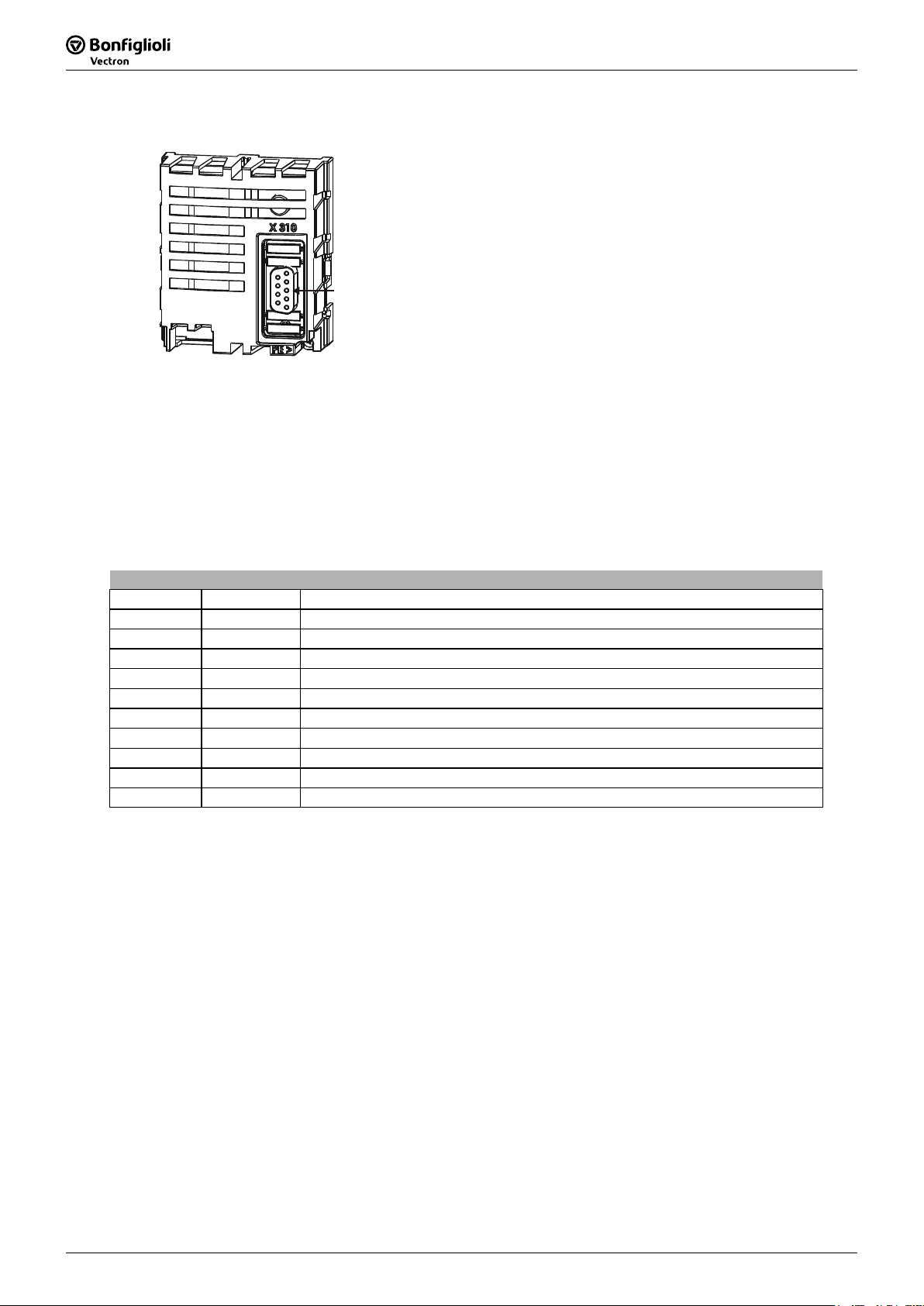
5 Connection
ed according
scriber can be activated
e to be used for the bus socket. They must all be suited for the 12 MBaud
The X310 (9-pol D-Sub) bus connector is occupi
to the Profibus-DP-Norm EN50170.
See the following table for details of the pin assignment.
X310
The bus termination necessary on the bus line in the physically first and last sub
via corresponding circuits in the bus connection sockets (e.g. built by Siemens).
Attention! The device will only communicate with the master if
− the master is connected to the mains (or powered by 24V DC)
− the device is connected to the mains (or powered by 24V DC)
− the first and the last subscriber on the connected branch have a correctly set bus
termination
− all other devices in between have no bus termination or a deactivated bus
termination.
Connection
Bus Connector X310
Pin Name Function
Housing Shield connected with PE
1 PE PE
2 not used 3 RxD/TxD-P positive Signal RxD/TxD-P, corresponding to RS485 B-Line
4 CNTR-P control signal for Repeater
5 DGND isolated Ground Connection for Bus Termination
6 VP isolated 5V for Bus Connection
7 not used 8 RxD/TxD-N negative Signal RxD/TxD-N, corresponding to RS485 A-Line
9 not used -
Only admissible types ar
transmission rate.
This is, for example, type Profibus connector 12 MBAUD (6ES7 972-0BA11-0XA0) from Siemens.
Only admissible types are to be used as a line for the Profibus (line type A).
This is, for example, type UNITRONIC-BUS L2/F.I.P. 1x2x0,64 from Lappkabel.
Attention! The line screen is to be connected to ground (PE) on both sides with good conductivity.
Probus DP V1 Agile 06/201012
Commissioning via the Operator Panel
6 Commissioning via the Operator Panel
A communication interface can be set up in the "Setup" menu of the Operator Panel. Further
communication parameters can be set in the "Para" menu.
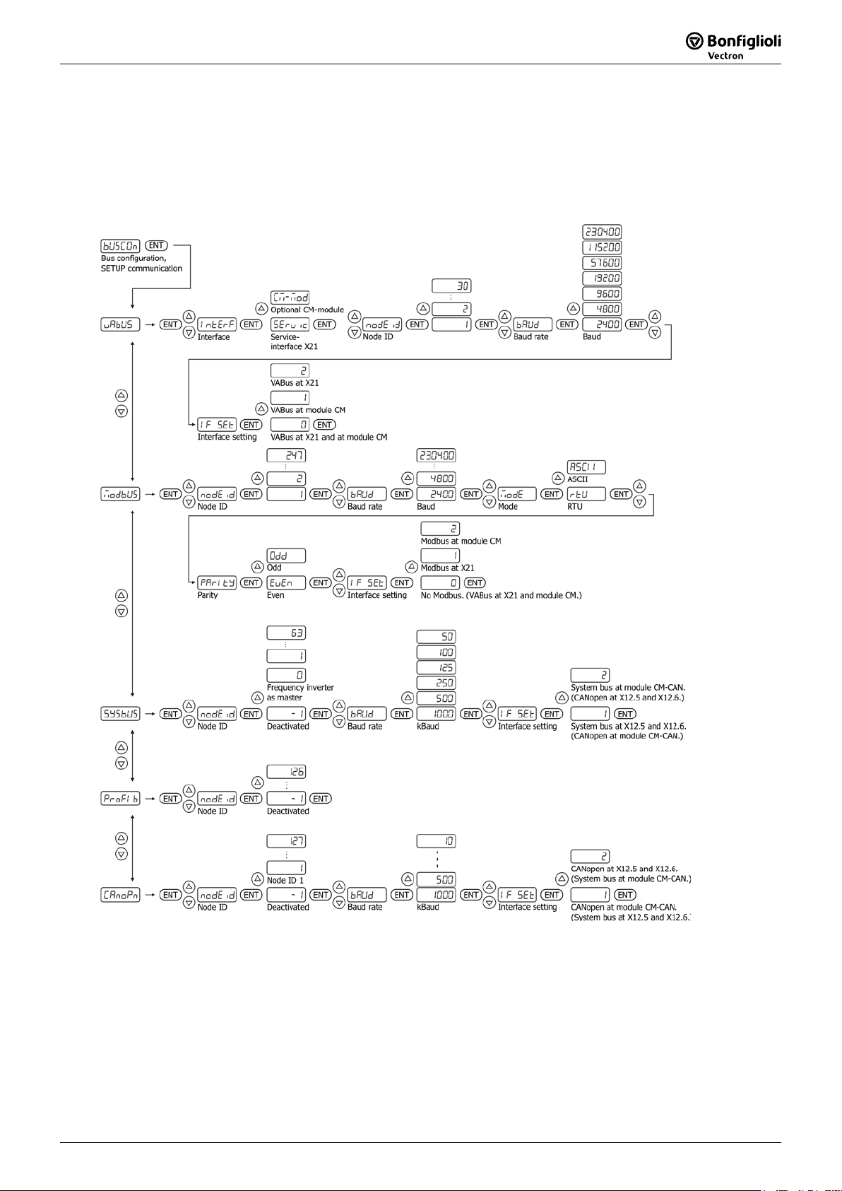
6.1 Menu for setting up the Communication
The communication interface can be set up quickly and simple via the Operator Panel.
Probus DP V1 Agile 1306/2010

6.2 Select the Protocol
4
• Select Profibus.
Select the "Setup" menu using the arrow keys.
Using the arrow keys select:
Setting up a Communication Interface (Bus Configuration)
Select a protocol using the arrow keys:
CANopen
Profibus
Systembus
Modbus
VABus
Commissioning via the Operator Panel
Display
EN T
EN T
EN T
6.3 Set the Communication Parameters
Parameter Display
391 Node Number
4
The selection is only possible if an optional CM-PDPV1 Communication Module is installed.
Probus DP V1 Agile 06/201014

Profibus
This document describes the possibilities and characteristics of the Profibus DP communication module
DP
PDPV1 is enclosed with the inverter
DP.
tively to the
PDPV1 is only possible
(hexadecimal). The device's
. The identification number and designation of the
PDPV1 it is possible to
e frequency inverter from the external control unit. Control
rameter 28) as with the Operator Panel or the
oftware does not exist. A change of parameters with an unknown meaning to
7 Profibus
CM-PDPV1 for the device series Agile.
For the Profibus-DP connection, the frequency inverter must be equipped with the Profibuscommunication module CM-PDPV1. The Profibus component CMas a separate part and must be fitted by the user.
Note: These instructions are not to be understood as fundamental information on Profibus-
They presuppose underlying knowledge of the methods and modes of effect of ProfibusDP on the part of the user.
In some sections, setting and display possibilities are described, alterna
Operator Panel, via the VPlus PC-Software. Operation of a PC with the VPlus PC-Software
on the frequency inverter with use of the Profibus component CMvia an optional interface adapter.
The Profibus component CM-PDPV1 has the ident number 0x0B2C
data set file has the designation BV__0B2C.GSD
GSD file were assigned by the Profibus User Organization in Karlsruhe, Germany.
Attention! With the help of the Profibus-DP communication module CM-
access ALL parameters of th
of the access via the Control Level (Pa
VPlus PC-S
user can lead to the inoperability of the frequency inverter.
Probus DP V1 Agile 1506/2010

Baud Rate Setting / Line Length
function and
9,6
19,2
45,45
93,75
187,5
DP. Each frequency inverter
ntification; this ID may only exist once in the system. The
No.
Description
Min.
Max.
Factory Setting
Profibus Node-ID
8 Baud Rate Setting / Line Length
The baud rate is not set explicitly. The Profibus component supports the Auto_Baud
independently determines the baud rate set on the bus.
The maximum line length recommended by the PNO correlates to the baud rate.
Profibus-DP Interface
Baud Rate/kBaud Max. Line Length/m
1200
1200
1200
1200
1000
500 400
1500 200
3000 100
6000 100
12000 100
9 Setting the Station Address
391 Profibus Node-ID
A maximum of 125 slave frequency inverters can be operated on the Profibusis assigned a node ID for its unambiguous ide
setting of the node ID is carried out via Parameter Profibus Node-ID 391.
Parameter Setting
391 Profibus Node-ID -1 126 -1
Note:
391 = -1 means Profibus function switched off.
Probus DP V1 Agile 06/201016

LED Indicators
The communication module has two bicolor LEDs which display the module status and the (Profibus)
When the inverter enters the error state a diagnostic event is sent from the inverter controller to the
a diagnostic message to the Profibus master. The Profibus
master device is then able to display the inverter error. The LED stops flashing after the
f these objects are NOT
PDPV1
10 LED Indicators
operation mode.
Operation Mode
State Indication
Off not online/no power
Green online, data exchange
Flashing Green online clear
Flashing Red (1 flash) parameterization error
Flashing Red (2 flashes) configuration error (*)
* Configuration Error
The configuration error indicates an incorrect configuration of the data exchange object.
See Chapter 13.1"Configuration Process on the DP Master".
Status
State Indication
Off not initialized/no power
Green initialized
Flashing Green initialized, diagnostic event present (*)
Red exception error (**)
* Diagnostic Event
CM-PDPV1. The CM-PDPV1 then sends
acknowledgement of the inverter error.
Note: Diagnostic events are handled by a S7-CPU with OB82/OB86. I
loaded the CPU enters the STOP state in the case of a diagnostic event.
** Exception Error
An exception error indicates a fatal error on the CM-PDPV1 or communication loss between CMand inverter controller. Check the inverter error message with the Operator Panel or VPlus.
Probus DP V1 Agile 1706/2010

11 Status Parameters
PDPV1 has two actual value parameters which display the current status of
Status Control
Status Fieldbus Module
Status Control
Status Fieldbus Module
WAIT_PROCESS
Waiting for connection to Profibus master
lly not of interest. These messages are of
the inverter can be set with
Profibus Error Reaction
0 -
No Reaction
Inverter remains in the current state.
Quick Stop” are only available when
Local/Remote
The Profibus module CMthe module itself as well as that of the controlling software in the inverter.
365 displays the software state of the controlling software in the inverter.
366 displays the module state.
Status Parameters
365
Wait_Process_PDP Waiting for connection to Profibus master
Wait_Process2_PDP Waiting for reconnection to Profibus master after
connection loss
Process_Active_PDP Connection to Profibus master established, Data-
Exchange with Profibus master running
366
PROCESS_ACTIVE Connection to Profibus master established,
Data-Exchange with Profibus master running
These parameters can show other messages that are usua
interest for BONFIGLIOLI VECTRON support in the case of problems and trouble shooting.
Description
Description
12 Error Behavior
393 Profibus Error Reaction
In the event of Profibus errors (e.g. Profibus OFF), the behavior of
393.
Parameter Setting
No. Description Min. Max. Factory
Setting
393 Profibus Error Reaction 0 5 1
Operation Mode 393 Function
1 - Error Inverter enters the error state.
2 - Coast to Stop Inverter power stages are switched off and drive stops in free run.
3 - Quick-Stop The drive is decelerated with the quick stop ramps.
4 - Ramp-Stop + Error The drive is decelerated with the ramp. An error is generated after
reaching standstill.
5 - Quick-Stop + Error The drive is decelerated with the emergency stop ramp. An error is
generated after reaching standstill.
Note: The operation modes “2 - Coast to Stop” and “3 -
412 is set to “1 - Control via Statemachine”.
Probus DP V1 Agile 06/201018

Setting PPO Type
As a function of the application in question, various process peripheral objects (PPOs) with differing
PDPV1 offers a wide range of PPO settings.
With the help of a hardware configuration tool the user is able to construct PPO settings as needed for
O4 and two additional objects (communication
The required object is to be set on the DP master in the hardware configuration. There is no setting for
e of the frequency inverter; it sets itself automatically to the projected
Handling of
verter. This object
causes additional busload because it sends its contents with every data exchange cycle,
tive function without the necessity of the PKW
s function is explained in
Each PZD object has two words of input/output data. The handling of this object is
13 Setting PPO Type
lengths and contents are used for data exchange. The CM-
his application.
Four predefined objects PPO1, PPO2, PPO3 and PP
object PKW, process data object PZD) are available for free configuration.
the required object on the sid
object.
Profibus - Objects
Object Object Length Object Length
Bytes Words
PPO 1 12 6
PPO 2 20 10
PPO 3 4 2
PPO 4 12 6
PKW 8 4
PZD 4 2
Note:
Further information on the contents of the objects is described in Chapter 16 "
the Objects".
The PKW object is used for accessing parameters (read/write) in the in
whether it is used or not. As an alterna
object, the CM-PDPV1 module supports the DP-V1 channel. Thi
Chapter 16.2 "Parameter Access via the DP-V1 Channel".
explained in chapter 16.3.1 "Data Types of OUT/IN-Objects".
Probus DP V1 Agile 1906/2010

Setting PPO Type
the example of a Siemens STEP7 hardware configurator. The process is
First of all the BV__0B2C.GSD is created in the Hardware Configurator (if not already present). This is
menu. Here you enter the path and
can be created on the Profibus line using
13.1 Configuration Process on the DP Master
The configuration process of the frequency inverter with the Profibus communication module CMPDPV1 is shown here using
principally valid for other configurations in an equivalent form.
carried out with by selecting the Extras\Neue GSD installieren
the name of the GSD-file (BV__0B2C.GSD).
If the GSD file is installed then the frequency inverter appears in the menu:
If the GSD file is installed then the frequency inverter appears in the menu:
PROFIBUS-DP\Weitere FELDGERÄTE\Antriebe\ACU/AGL-DPV1
From this position a ACU/AGL-DPV1 frequency inverter
drag & drop.
Probus DP V1 Agile 06/201020

Setting PPO Type
.
cy inverter with Station
1 PKW Object
8 bytes or 4 words, communication objects (input/output)
PDPV1 offers four predefined objects (PPO1…4) to be compatible to the former
A restriction violation results in a configuration error message from the PLC on the Profibus
The six possible objects PPO1 to PPO4, PKW and PZD are available in the ACU/AGL-DPV1 menu
The desired object can be assigned to the frequency inverter using drag and drop.
The screen copy from the STEP7 Hardware Configurator shows a frequen
Address 3 and a customer-specific configuration.
The above configuration setting is:
4 PZD Objects 16 bytes or 8 words, process data objects (input/output)
Note: − The data direction IN/input and OUT/output is from the master's point of view.
− Every single configured PZD object results in two word (4 byte) objects PZDn PZDn+1
for both input and output.
− The CMCM-PDP and two additional objects PKW (communication channel) and PZD (process
data) for application specific configurations.
Restrictions for user defined configuration settings:
− The PKW object is allowed only once as the first object.
− As a minimum one PZD object must be configured.
− The resulting number of all objects must be less than or equal to 36 bytes (18 words).
Note:
start up cycle. Also the Operation Mode Led on the CM-PDPV1 flashes red (2 flashes).
Probus DP V1 Agile 2106/2010

Commands SYNC / FREEZE
The Profibus component supports the Profibus commands SYNC/UNSYNC and FREEZE/UNFREEZE. These
their input data. They are then read out in sequence by the
bus master. As all the slaves keep their inputs simultaneously with the FREEZE command, the bus master is
is state is
With the SYNC command, all the slaves retain their current outputs. Subsequently arriving data are not put
slaves and activate
all the slaves simultaneously with the UNSYNC command. They immediately transfer the buffer data to
d configured by its master on the bus, there is a
service, in which the output data are
.
called bus
rotation time, is a function of the transmission rate, the number of subscribers and the size of the objects
h transmission rate and short objects being exchanged, bus
It is therefore sensible to configure the objects to suit the application. Depending on the application the
The configured data exchange objects have principally two components, which are either completely, partly
or not at all existent with the differing object configurations. These components are the communication
rameters in the
frequency inverter. An exception is formed by the string parameters, to which there is NO access. The
shake process and lasts for a number of
(PZD objects) is processed in every cycle. The reference values are accepted
14 Commands SYNC / FREEZE
commands are used to synchronize a number of slaves.
With the FREEZE command, all the slaves keep
given a process pattern of all the slaves at a defined time. With the UNFREEZE command, th
cancelled and the slaves update their inputs again.
through to the outputs, but buffered. The bus master can give new commands to the
their outputs with the UNSYNC command.
15 Available Objects / Scanning Times
If a Profibus slave has been recognized, parameterized an
cyclic exchange of data with the Profibus DATA_EXCHANGE
transmitted from the master to the slave and the input data from the slave to the master in one cycle
The repetition rate with which the slaves carry out the exchange of data with the master, the so-
transmitted. If there are few subscribers, a hig
rotation times of 1 to 2 ms are possible.
focus can be transmission speed, number of objects or a combination of both.
channel and the process data channel.
The communication channel (PKW object) is used for accessing (write/read) pa
communication proceeds according to a firmly defined handDATA_EXCHANGE cycles.
The process data channel
and the actual values forwarded. Therefore a data update takes place with every DATA_EXCHANGE.
Direction of transmission Master
Communication Channel Process Data Channel
PKW area PZD area
PKE IND PWE PWE PZD 1 PZD 2 PZD x PZD x PZD x PZD x
PWEh PWEl STW HSW Outx Outx Outx Outx
PKW Parameter identification value
PZD Process data channel STW = Control word HSW = Main reference value
Outx = user defined
Slave (OUT)
Probus DP V1 Agile 06/201022

Available Objects / Scanning Times
The consistency area describes the parts of the object which must have consistent contents. The
the configuration data of the GSD file and have effects on the
possible access mechanisms on the part of the DP master. In this way, the 8 bytes of the
communication channel in a PLC of type Siemens S7 can only be reached via the special functions
. The words of the process data channel are directly
objects you are able
defined configurations
munication channel
is presupposed for the position of
f the DP master
supports the Intel format, Low/High byte are to be swapped on the master side before
Direction of transmission Slave
Master (IN)
Communication Channel Process Data Channel
PKW area PZD area
PKE IND PWE PWE PZD 1 PZD 2 PZD x PZD x PZD x PZD x
PWEh PWEl ZSW HIW Inx Inx Inx Inx
PKW Parameter identification value
PZD Process data channel ZSW = State word HIW = Main actual value
Inx = user defined
Consistency area
Communication Channel Process Data Channel
PKW area PZD area
PKE IND PWE PWE PZD 1 PZD 2 PZD x PZD x PZD x PZD x
full length word word word word word word
consistency states are encrypted in
SFC14 (DPRD_DAT) and SFC15 (DPWR_DAT)
addressable as periphery input/output words (PEW, PAW).
Communication Channel Process Data Channel
PKE IND PWEh PWEl PZD1 PZD2 PZD3 PZD4 PZD5 PZD6
PPO1
PPO2
PPO3
PPO4
PPO1 … PPO4 are predefined configurations. With the help of the PZD- and PKWto build your own application specific configuration.
The communication channel is always treated identically. This is valid for the pre
PPO1/PPO2 and custom specific configuration with communication object PKW.
The process data channel objects PZD1/PZD2 are firmly defined and its contents cannot be altered.
The contents of process data channels PZD3 to PZD 18 (maximum, without com
PKW !) is user defined.
Note: In the data transmission, the Motorola format
Low/High byte first, as is also supported by a PLC of the type Siemens S7. I
transmission and after receipt.
Probus DP V1 Agile 2306/2010

Available Objects / Scanning Times
PDPV1 and the inverter's
verter is a function
Scan Time
Scan time defines the data update cycle between the Profibus module CMcontroller which processes the Profibus data. This scan time is independent of the bus rotation time.
Regardless of the transmission speed on the Profibus, the scanning time of the in
of the configured objects and the resultant object length (number of bytes).
Scan Time
No. of configured
Controller/CM-PDPV1
bytes words [ms]
Frequency Inverter
4 2 2
8 4 2
12 6 2
16 8 2
20 10 2
24 12 2
28 14 2
32 16 2
36 18 4
The scan time is dependent on the number of configured objects.
Probus DP V1 Agile 06/201024

Handling of the Objects
as, for example, supported by the S7 PLC from
Siemens. Thus, the high byte is on the lower byte of the telegram and the low byte on the higher
module with Systembus) a Systembus address
is set on the low byte of “Index” (SB/Byte No. 3). With the help of this parameter the
The request and reply identifications are stored in the AK area. If no parameter processing is to be
(SPM), the readiness for spontaneous report processing can be switched on and off (0 =
ous report processing is not supported, so SPM
Parameter values (= data) of the type Integer/Unsigned Integer (16 Bit) and Long (32 Bit) can be
over
mation on the
16 Handling of the Objects
This chapter describes the handling of the communication channels like i.e. Process data channel and
Parameter data channel.
16.1 Parameter Access via Communication Channel PKW
The communication channel (PKW area) has the following structure:
Designation
Content
Byte No. 0 Byte
The data is transmitted in the Motorola format
byte.
Note: The data set is always on the high byte of "Index“ (data set/Byte No. 2).
If the Systembus function is available (EM-
access to a Systembus subscriber is possible. For details see the Systembus manual.
PKE High-Byte Low-Byte
Bit 15 14 13 12 11 10 9 8 7 6 5 4 3 2 1 0
AK: Request or reply identification (value range 0 ..15)
SPM: Toggle bit for spontaneous result processing
PNU: Parameter number (value range 1 to 1599)
PKE PKE
Parameter
identification
High
Byte
No.
Structure of the Parameter Identification (PKE):
AK SPM PNU
Content
High
Byte
0 Byte
PKW Area
No.
Parameter
identification
High
Byte
0 Byte
No.
Content
High
Byte
0 Byte
No.
carried out, the “no request” type of function is to be set.
With bit 11
OFF, 1 = ON, in the present application, the spontane
is always 0).
The PNU area transmits the number of the parameter to be processed.
written and read. The data type is specified in the request identification. In data set changecapable parameters (array), the required data set is stated in the Index Byte (Byte 2).
Note: An Excel file, which is available on request, exists for the necessary infor
parameters with regards to the data type and data set change-over capability.
Note: To obtain access to the PKW object on a S7 PLC the functions SFC14/15 must be used.
Probus DP V1 Agile 2506/2010

16.1.1 Request Identification
Structure of the request identification AK (output data set, Master Slave)
over capable parameters; the required data must be specified in
Structure of the reply identification AK (input data set, Slave Master)
If the reply identification = 7 (request cannot be implemented), an error code is inserted in PWE low
Parameter cannot be read
Fault occurred in reading the EEPROM
Fault occurred in writing the EPROM
Check sum fault in EEPROM occurred
Parameter may not be written in operation
Handling of the Objects
Request
Identification AK
0 - no request
1 int/uint , long read parameter value
2 int/uint write parameter value int/uint
3 long write parameter value long
6 int/uint , long Array read parameter value Array
7 int/uint Array write parameter value int/uint Array
8 long Array write parameter value long Array
Array: Applies to data set change-
data set/INDEX. Otherwise, data set/INDEX = 0.
Data type Function
16.1.2 Response Identification
Reply
Identification AK
0 - no request
1 int/uint transmit parameter value int/uint
2 long transmit parameter value long
4 int/uint Array transmit parameter value int/uint Array
5 long Array transmit parameter value long Array
7 - request cannot be implemented
8 - no control sovereignty for PKW interface
Data type Function
(Byte 6/7).
If the reply identification = 8 (no control sovereignty), the master has no writing right to the slave.
16.1.3 Fault Messages
Coding of the fault messages in the reply data set PWE-Low/Low-Byte in Byte 7 (Slave Master):
Fault No. (dec.)
acc. to
PROFIDRIVE
0 Inadmissible parameter number PNU
1 Parameter value cannot be altered
2 Lower or upper parameter value limit exceeded
3 Faulty data set
4 No data set change-over capable parameter
5 Wrong data type
18 Other fault
20 Systembus not responding
Extension Meaning
101
103
104
105
106
107 Values of the data sets differ
108 Unknown request
Meaning
Probus DP V1 Agile 06/201026

Handling of the Objects
ger than zero will
SYS module), the requested device doesn’t respond.
Check, that the requested device is supplied with power and that the Systembus Node ID in the Index
tion of the
The parameter list also provides information on the display format of a parameter and its type
The values transmitted are always integer values. For values with decimal places, the decimal point is
cation, the data
over
n the PWE area; as a 16 Bit value (int/uint) it occupies
If parameters with four data values are set via data set = 0, all four data sets are set to the same
ansmitted value. A read access with data set = 0 to such parameters is only successful if all four
cally into the EEPROM on the controller.
If values are to be written cyclically with a high repetition rate, there must
be no entry into the EEPROM, as it only has a limited number of
ble writing cycles (about 1 million cycles). If the number of
without a writing cycle
ritten
cification of the
ters is to be considered as a further special
over capable parameter are to be set to the same value in all
Note:
The fault number „20“ can be caused by different reasons.
If you do not use the Systembus: Check, that the Low-Byte is “0” (Zero). Values big
try to communicate with a Systembus connected device instead of the Profibus device.
If you use Systembus (in example via an EM-
Low Byte and the parameterization of the requested device match.
16.1.4 Parameters, Data Set Selection and Cyclic Writing
Parameters to be set can be taken from the parameter list referring to the configura
standard operating instructions. In the parameter list, state whether a parameter is data set changeover capable (data set/INDEX = 1 to 4) or only exists once (data set/INDEX = 0).
(int/uint/long). String parameters cannot be transmitted due to the possible number of bytes.
not transmitted.
The word IND passes on the required data set of the parameter. In the present appli
set number 0 is assigned to existing parameters; a selection from multiple (data set changecapable) existing parameters is carried out by inserting a number from 1 to 4.
The actual parameter value is transmitted i
PWEl, as a 32 Bit value (long) PWE high and PWE low, with the high word located in PWE high.
tr
data sets are set to the same value. If this is not the case an error is reported.
Caution! The values are entered automati
admissi
admissible writing cycles is exceeded, the EEPROM is destroyed.
To avoid this, cyclically written data should be transmitted into the RAM (only
onto the EEPROM). Then the data are not stored secure against zero voltage and must be w
again after a Power off/on.
This mechanism is activated by the target data set being increased by five in the spe
data set (IND).
Entry only into the RAM:
EEPROM RAM
Entry into data set 0 Data set (IND) = 5
Entry into data set 1 Data set (IND) = 6
Entry into data set 2 Data set (IND) = 7
Entry into data set 3 Data set (IND) = 8
Entry into data set 4 Data set (IND) = 9
Writing access to data set change-over capable parame
point. If the values of a data set changedata sets, the parameter can be written via the data set (IND) 0.
Probus DP V1 Agile 2706/2010

Handling of the Objects
answered with a reply from the slave. Each PPO can only accept
shake procedure between master and
reply identification must = 0. The master sets its request
0. Now, the reply
est identification
identification = 0
16.1.5 Sequence of Communication
A request from the master is always
one request or one reply at a time. In this way, a defined handslave must be complied with.
In the initial situation, the request and
identification and waits for the slave to change the reply identification from 0 to ≠
from the slave is available and can be evaluated. Thereupon, the master sets its requ
= 0 and waits for the slave to change the reply identification from ≠ 0 to 0. With this, the
communication cycle is completed and a new one can start.
Attention! The slave only replies to new requests if it has reacted to the request
with the reply identification = 0.
Probus DP V1 Agile 06/201028

Handling of the Objects
16.1.6 Communication Examples
Parameter Setting
No. Description Type Write /
Read
400 Switching frequency P-W S/L x 1 8 2
480 Fixed frequency 1 P[I]-D S/L xxxx.xx Hz -999.00 999.00 5.00
Example 1:
Parameter 400 is one word (P-W), int, not data set switch-over capable and is to be read.
Request from Master:
AK = 1 (Request Identification = read parameter value
PNU = 400 (= 0x190)
IND = 0
PWEh = 0
PWEl = 0
PKW area
Designation PKE IND PWE high PWE low
Content Parameter
Identification
High
Byte
0x11 0x90 0 0 0 0 0 0
Byte No. 0 1 2 3 4 5 6 7
Low
Byte
Index Parameter value
High
Byte
Format Min. Max. Fact. Sett.
Parameter value
Low
Byte
High Word
High
Byte
Low
Byte
Low Word
High
Byte
Low
Byte
Reply from Slave:
AK = 1 (reply identification = transmit parameter value int/uint)
PNU = 400 (= 0x190)
IND = 0
PWEh = 0
PWEl = value
PKW area
Designation PKE IND PWE high PWE low
Content Parameter
Identification
High
Byte
0x11 0x90 0 0 0 0 0 value
Byte No. 0 1 2 3 4 5 6 7
Low
Byte
Index Parameter value
High Word
High
Byte
Low
Byte
High
Byte
Low
Byte
Parameter value
Low Word
High
Byte
Low
Byte
Probus DP V1 Agile 2906/2010

Handling of the Objects
Example 2
over capable, and is to be written.
Byte No.
0123456
7
Parameter 480 is a double word (P[I]-D), long, data set changeThe target data set is data set 3.
Reference value = -300.00 Hz (-30000 is transmitted)
The negative value is portrayed as follows in accordance with integer arithmetic: 0xFFFF8AD0
Request from Master:
AK = 8 (request identification = write parameter value long Array)
PNU = 480 (= 0x1E0)
IND = 3
PWEh = 0xFFFF
PWEl = 0x8AD0
PKW area
Designation PKE IND PWE high PWE low
Content Parameter
Identification
High
Byte
Low
Byte
Index Parameter value
High Word
High
Byte
Low
Byte
High
Byte
Low
Byte
Parameter value
Low Word
High
Byte
Low
Byte
0x81 0xE0 3 0 0xFF 0xFF 0x8A 0xD0
Byte No. 0 1 2 3 4 5 6 7
Reply from Slave:
AK = 5 (reply identification = transmit parameter value long Array)
PNU = 480 (= 0x1E0)
IND = 3
PWEh = 0xFFFF
PWEl = 0x8AD0
PKW area
Designation PKE IND PWE high PWE low
Content Parameter
Identification
High
Byte
Low
Byte
Index Parameter value
High Word
High
Byte
Low
Byte
High
Byte
Low
Byte
Parameter value
Low Word
High
Byte
0x51 0xE0 3 0 0xFF 0xFF 0x8A 0xD0
Low
Byte
Probus DP V1 Agile 06/201030

16.2 Parameter Access via the DP-V1 Channel
channel.
This is an alternative to the usage of the communication object PKW in the data exchange object. The
eter access are special Profibus telegrams that are sent only when a
ject, the V1 telegrams can access all
ent methods included
V1
The two different modes are necessary because V1 telegrams are handled differently on the various
The standard telegram addresses a device by its Profibus node ID and selects the parameters by two 8 bit
. If the Profibus master device supports the direct setting of the Profibus
Standard” and the handling described for
channel. These functions do not offer an
. The addressing is accomplished by the diagnostic address
d variable object for the PLC
(8 bit). If the Profibus master device does not support the setting of Profibus node ID,
S7 compatible” and the handling described for this
V1 Mode the parameter data to be read or written uses the Motorola format. The
The Profibus communication module CM-PDPV1 provides the possibility to use the Profibus V1-
PKW object is always sent on the bus, whether it is used or not, and therefore causes needless busload.
The V1 telegrams for param
parameter access is necessary. Contrary to the usage of the PKW ob
types of parameters including string parameters.
To be compatible to different types of Profibus master devices there are two differ
for the V1-channel. The behavior of the CM-PDPV1 concerning the different methods is set with DP-
Mode 329.
329 DP-V1 Mode
Parameter Setting
No. Description Min. Max. Factory Setting
329 DP-V1 Mode 1 2 2
Operation Mode Function
1 - Standard Standard usage of V1 channel
2 - S7 compatible S7 PLC usage of V1 channel
Note: To get access to the V1-channel on a S7 PLC the functions SFC52/53 must be used.
Profibus master implementations.
objects named
node ID,
slot
slot
and
and
index
index
DP-V1 Mode 329 must be set to “1 –
this setting must be used.
A S7 PLC uses two special functions SFC52/53 for the V1independent setting for node ID,
(with
slot
always set to 0) of the device to be accessed. The only available an
application is
slot
and
index
index
DP-V1 Mode 329 must be set to “2 –
slot
and
index
setting is to be used.
For both types of DPnumber of bytes depends on the parameter data type.
Parameter data types and byte order
Byte 0 1 2 3 4 5 … …. max. 98
Data Type
Content High Byte, Low Byte
Data Type
Content High Byte, Low Byte
Data Type
Content first char
uint/int
long
string
uint/int = 2 Bytes
long = 4 Bytes
string = 1 … 99 Bytes
Probus DP V1 Agile 3106/2010

Handling of the Objects
A parameter is accessed by its parameter number and data set number. The valid range for parameter
Parameters, Data Set Selection
. With the setting of the
the selection of parameter number and data set number for
read/write is done. The number of bytes to be transferred (read/write) depends on the parameter's
ol reacts
The Standard Mode also offers a special functionality to obtain access to additional inverters via the
PDPV1 and several additional inverters
= 0 all parameter
16.2.1 Operation Mode "Standard"
number is 0 … 1599, the range of data set number is 0 … 9.
Note: For the handling of data set selection see chapter 16.1.4 "
and Cyclic Writing".
slot
and
The standard mode uses the direct setting of Profibus node ID,
two 8 bit objects
data type. In the case of a write cycle and an invalid number of bytes the CM-PDPV1 protoc
with an error message.
Calculation of slot and index:
Calculate an "application data index" ADI as a 16 bit unsigned integer with
ADI = (Parameter number + 1) + (2000 * (Data Set number + 1))
Calculate the value of
slot
slot
and
and
index
index
with
index
slot = (ADI – 1) / 255
index = (ADI – 1) modulo 255
Example:
Parameter number = 480
Data Set number = 3
ADI = (480 + 1) + (2000 * (3 + 1)) = 8481
slot = (8481 - 1) / 255 = 33
index = (8481 - 1) modulo 255 = 65
The parameter data structure is explained above.
Access to Systembus:
Systembus. For example, there exists one inverter with CMcoupled to the first one via the Systembus.
This function can be implemented with CM-PDPV1 via the virtual parameter 1600.
After power on/reset this virtual parameter 1600 is set to zero. With 1600
accesses by V1 channel are allocated to the inverter with CM-PDPV1 itself.
Probus DP V1 Agile 06/201032

Handling of the Objects
is written to the
A parameter is accessed by its parameter number and data set number. The valid range for parameter
Parameters, Data Set Selection
. There are two steps necessary
ferred (read/write) depends on
DPV1
In the first step the desired parameter number, data set number and Systembus node ID are written.
. The object to be sent has 4 bytes with the following
The desired parameter data can now be read or written by sending a read or write request with
i
To obtain access to parameters of inverters via the Systembus, parameter 1600
desired Systembus node ID.
The data type of parameter 1600 is unsigned integer with a valid data range = 0 … 63.
Parameter 1600 can be read and written.
16.2.2 Operation Mode "S7 Compatible"
number is 0 … 1599, the range of data set number is 0 … 9.
Note: For the handling of data set selection see chapter 16.1.4 "
and Cyclic Writing".
The S7-compatible Mode only allows the setting of the object
index
for reading/writing one parameter. The number of bytes to be trans
the parameter's data type. In the case of a write cycle and an invalid number of bytes the CM-P
protocol reacts with an error message.
Step 1:
This message is sent with
index
set to 1
structure:
Data Structure for Index = 1:
Byte 0 1 2 3
Content Parameter Number
High Byte Low Byte
Data Set Number Systembus
Address
Parameter number = 0 …. 1599
Data Set = 0 …. 9
Systembus Address = 0 …. 63
Step 2:
ndex
set to 2.
The parameter data structure is explained above.
Probus DP V1 Agile 3306/2010

16.3 Process Data Channel
is described. The mandatory process data objects PZD1/2 are
PZD2, Reference Value
The PZD 3 … 18 objects can be used in an application specific way. Inside the inverter these objects
t objects (data received from Profibus master) and input
The "Word" data type can be used for percentage, current and torque variables. Current and torque
PZDn are
13
In this chapter the handling of the PZDs
described in chapters 16.4.1 "PZD1, Control Word / Status Word" and 16.4.5 "
/ Actual Value".
are represented as sources for PZD Ou
parameters for sources (data to be sent to the Profibus master).
Note: Input/output are defined from the Profibus master point of view.
16.3.1 Data Types of OUT/IN-Objects
Data Type "Boolean"
The valid values for boolean are FALSE/0x0000 and TRUE/0xFFFF.
Data Type – Boolean
Boolean
value
OUT/IN-PZDn Boolean FALSE 0x0000
OUT/IN-PZDn Boolean TRUE 0xFFFF
Data Content
hexadecimal
Handling of the Objects
n = 3 … 18
Data Type "Word"
are possible in applications with field-orientation. The scalings in question are described below.
Word Data Type "Percentage"
The value range for percentage values is -300.00 to +300.00%. The values in OUT/INdisplayed with a multiplication factor of 100.
Word Data Type – Percentage
Data Content
hexadecimal
Data Content
decimal
Logical
Interpretation
OUT/IN-PZDn Word 0x8AD0 - 30000 - 300,00%
OUT/IN-PZDn Word 0x0000 0 0,00%
OUT/IN-PZDn Word 0x7530 + 30000 + 300,00%
n = 3 … 18
Word Data Type "Current"
For the current, calculation must be done in the device-internal scaling.
The scaling is:
Reference value = (Reference current [A] / Scaling current [A]) · 2
213= 8192 (decimal) = 0x2000 (hexadecimal)
Probus DP V1 Agile 06/201034

Handling of the Objects
ing. The scaling
for a torque value is identical to the specification of the reference current (see Current). If the
specific
31
31
Word Data Type "Torque"
For the torque specification, the calculation must be done in the device-internal scal
machine is operated with nominal flux, a reference torque corresponds to a reference current.
Note: The equation stated for current (torque) applies for operation with nominal flux. If a
machine is operated in the field weakening area, this is to be considered in the
specification values.
If the current or torque variables are used, please take into account the devicescaling.
Data Type "Long"
The "Long" data type can be used for the frequency and position variables.
Frequencies use the internal notation of the inverter
(xxx Hz / 4000 Hz) * 2
31
.
Examples:
50,00 Hz (50,00 / 4000,00) * 2
-80,00 Hz (-80,00 / 4000,00) * 2
= 0x01999999
= 0xFD70A3D8
Data Type – Long
Data Content
hexadecimal
Data Content
decimal
OUT/IN-PZDx/y Long 0xnnnnmmmm Application-
specific
x/y = 3/4, 5/6, … 17/18
Logical
Interpretation
Application-
specific
Probus DP V1 Agile 3506/2010

Handling of the Objects
The table below lists the available output sources of the PZD Out objects. The content of the sources
data types the equivalent sources must be connected to
One PZD out object can be used for one data type only (depending on the application
16.3.2 Profibus Output Sources (OUT-PZD x)
depends on the application. For the different
the inverter input parameters.
Note: − The availability of Out sources depends on the number of configured PZD objects.
− Every configured PZD object consists of either two Boolean, two word or one long
output object.
−
requirements).
− The first configured PZD object (mandatory) represents the PZD1/2 with fixed
contents and functions.
No. of
configured
PZD Objects
Boolean Sources Word Sources Long Sources
Name Source
No.
Name Source
No.
Name Source
2 Out-PZD3 Boolean 640 Out-PZD3 Word 656 Out-PZD3/4 Long 672
Out-PZD4 Boolean 641 Out-PZD4 Word 657
3 Out-PZD5 Boolean 642 Out-PZD5 Word 658 Out-PZD5/6 Long 673
Out-PZD6 Boolean 643 Out-PZD6 Word 659
4 Out-PZD7 Boolean 644 Out-PZD7 Word 660 Out-PZD7/8 Long 674
Out-PZD8 Boolean 645 Out-PZD8 Word 661
5 Out-PZD9 Boolean 646 Out-PZD9 Word 662 Out-PZD9/10 Long 675
Out-PZD10 Boolean 647 Out-PZD10 Word 663
6 Out-PZD11 Boolean 648 Out-PZD11 Word 664 Out-PZD11/12 Long 676
Out-PZD12 Boolean 649 Out-PZD12 Word 665
7 Out-PZD13 Boolean 650 Out-PZD13 Word 666 Out-PZD13/14 Long 677
Out-PZD14 Boolean 651 Out-PZD14 Word 667
8 Out-PZD15 Boolean 652 Out-PZD15 Word 668 Out-PZD15/16 Long 678
Out-PZD16 Boolean 653 Out-PZD16 Word 669
9 Out-PZD17 Boolean 654 Out-PZD17 Word 670 Out-PZD17/18 Long 679
Out-PZD18 Boolean 655 Out-PZD18 Word 671
Note: − Every source can be connected to an inverter input parameter with the same data
type. This method is the same as used with Systembus receive objects.
− Boolean sources are representatives for Boolean objects.
− Word sources are representatives for current or torque objects.
− Long sources are representatives for frequency or position objects.
No.
Probus DP V1 Agile 06/201036

Handling of the Objects
tent of the sources
types the equivalent input parameters must be
2/1303/1307/1308) is FALSE or
device series ACT with
sponding objects for
16.3.3 Profibus Input Parameters (IN-PZD x)
The table below lists the available input parameters of the PZD In objects. The con
depends on the application. For the different data
connected to the inverter sources.
Note: − The availability of In parameters depends on the number of configured PZD objects.
− Every configured PZD object consists of either two Boolean, two word or one long
input parameter.
− One PZD In object can be used for one data type only (depending on the application
requirements).
− The first configured PZD object (mandatory) represents the PZD1/2 with fixed
contents and functions.
1300 … 1339 IN-PZD x
No, of
configured
PZD Objects
Boolean Parameter Word Parameter Long Parameter
Name Parameter
No.
Name Parameter
No.
Name Parameter
2 In-PZD 3 Boolean 1300 In-PZD 3 Word 1302 In-PZD 3/4 Long 1304
In-PZD 4 Boolean 1301 In-PZD 4 Word 1303
3 In-PZD 5 Boolean 1305 In-PZD 5 Word 1307 In-PZD 5/6 Long 1309
In-PZD 6 Boolean 1306 In-PZD 6 Word 1308
4 In-PZD 7 Boolean 1310 In-PZD 7 Word 1312 In-PZD 7/8 Long 1314
In-PZD 8 Boolean 1311 In-PZD 8 Word 1313
5 In-PZD 9 Boolean 1315 In-PZD 9 Word 1317 In-PZD 9/10 Long 1319
In-PZD 10 Boolean 1316 In-PZD 10 Word 1318
6 In-PZD 11 Boolean 1320 In-PZD 11 Word 1322 In-PZD 11/12 Long 1324
In-PZD 12 Boolean 1321 In-PZD 12 Word 1323
7 In-PZD 13 Boolean 1325 In-PZD 13 Word 1327 In-PZD 13/14 Long 1329
In-PZD 14 Boolean 1326 In-PZD 14 Word 1328
8 In-PZD 15 Boolean 1330 In-PZD 15 Word 1332 In-PZD 15/16 Long 1334
In-PZD 16 Boolean 1331 In-PZD 16 Word 1333
9 In-PZD 17 Boolean 1335 In-PZD 17 Word 1337 In-PZD 17/18 Long 1339
In-PZD 18 Boolean 1336 In-PZD 18 Word 1338
The default setting for all input parameters (except parameters 130
zero.
The default setting for input parameters 1302/1303/1307/1308 is compatible to
CM-PDP module:
No.
In-PZD 3 Word 1302 = 770 PDP absolute current
In-PZD 4 Word 1303 = 771 PDP active current
In-PZD 5 Word 1307 = 772 warning status
In-PZD 6 Word 1308 = 773 error status
Note: − If one object is set to a specific source no., be sure that the corre
the same location are set to their default values. This method is the same as used
with Systembus transmit objects.
− Boolean inputs are representatives for boolean objects.
− Word inputs are representatives for current or torque objects.
− Long inputs are representatives for frequency or position objects.
Probus DP V1 Agile 3706/2010

Handling of the Objects
orientation,
forming current is displayed, in applications with a v/f characteristic control,
14
Rated current
is used as a
FUN
FUNIFUN
Note: The displayed "PDP active current" depends on the control system. In field-
the torquethe active current, which is also a measure for the torque.
The “PDP absolute current” (r.m.s. current) is always positive. Active current and torqueforming current have a sign prefixed.
Positive currents = motor
Negative currents = generator operation.
Current Scaling
Standardization
Reference value Binary Decimal Hexadecimal
+ 100% + 2
16384 0x4000
The possible range = ±200% = +32768 to -32768 = 0x8000 to 0x7FFF
For the internal scaling, the data set change-over capable parameter
reference.
Parameter Setting
No. Description Min. Max. Factory Setting
371 Rated Current 0,01 · I
10 · I
371
Probus DP V1 Agile 06/201038

Handling of the Objects
notation to frequency values in
14
14
sion. The benefit
PZD objects is shown in the
16.4 Frequency Conversion PDP Word to/from Inverter Internal Notation
1370 In-F-PDP-word 1
1371 In-F-PDP-word 2
1372 In-F-intern-long 1
1373 In-F-intern-long 2
1374 In-F-Convert Reference
The function
Convert PDP/intern
converts frequency values in Profibus
device-internal notation and vice versa. See Chapter 16.4.5 "PZD2, Reference Value / Actual Value".
The scaling for In_F_PDP_word1/2 and Out_F_PDPconv_word1/2 is:
Standardization
Reference Value Binary Decimal Hexadecimal
+ 100% + 2
- 100% - 2
16384 0x4000
49152 0xC000
The possible range = ±200% = +32768 to -32768 = 0x7FFF to 0x8000
This function uses its own reference value
Convert-Reference
1374 for data conver
of this function is the usage of the word data type for frequency values, instead of long.
Note: The usage of this function and the usage of In-PZD/Out-
sample project documented with:
− CM_PDPV1_conf.pdf Cluster with one inverter and CM-PDPV1 and three additional
inverters coupled by Systembus
− CM_PDPV1_S7.pdf Functional description
− CC_0B2C.zip Complete STEP7 project including samples for In/Out-PZD usage
and parameter access via PKW object and V1 channel
− S7-SoftwareOB1.pdf Listing of OB1 from STEP7 project
Probus DP V1 Agile 3906/2010
Handling of the Objects
verter in the output
The control of the frequency inverter can be carried out with three different operation modes. These
Local/Remote
Parameter
Setting
For operation on the Profibus, only the settings 0, 1 and 2 are relevant. The remaining settings relate
The Start and Stop command as well as the statement of the direction
The Start and Stop command as well as the statement of the direction
f rotation are set via the DRIVECOM State machine of the
The Start and Stop command as well as the statement of the direction
Control word STW and state word ZSW have different contents depending on the operation mode. In
each case, all or only some of the bits in the control word are relevant and also only certain feedbacks
ater in the descriptions of the three possible
Local/Remote
over capable. Thus, switching over
between various operation modes via the data set selection is possible. For example, it is
to control a frequency inverter via the bus and to activate a local emergency
over is also visible via the state
Control word
PZD1.
Status word
ally on the frequency inverter via contact inputs, or via the
Data Set Selection
Data Set Selection
Data Set
has been set to 1, 2, 3, or 4, then the corresponding data set has been activated. Data
over only occurs if the frequency
Active data set
Active data set
states the activated data set with the value 1, 2, 3 or 4. This is independent of whether the data
Data Set Selection
16.4.1 PZD1, Control Word / Status Word
In PZD1, the master gives its control commands (control word) to the frequency in
data set and receives the information on its state (status word) in the input data set.
412 Local/Remote
are set via the data set change-over capable parameter
No. Description Min. Max. Factory Setting
412 Local/Remote 0 44 44
to the possibilities of control via the KP500 control unit.
Operation Mode Function
0 - Control via contacts
Control via
1 -
state machine
Control via
2 -
remote contacts
are possible via the status word. These are explained l
operation modes.
Note:
Parameter
of rotation are set via digital signals.
o
communication interface.
of rotation are set via logic signals by the communication protocol.
412 is data set change-
412.
possible
operation if the bus master breaks down. This switchword (Bit Remote).
Note:
414 Data Set Selection
Data set change-over can be carried out loc
bus. For data set change-over via the bus, Parameter
No. Description Min. Max. Factory Setting
414 Data Set Selection 0 5 0
With
Parameter
Avoid, changing Control word 410 via parameter access.
Parameter
Parameter Setting
414 = 0, data set switch-over via contact inputs is active. If
410 is linked internally to the Control word STW of Out-
411 is linked internally to the Status word ZSW of In-PZD1.
414 is used.
Selection 414
set switch-over via the contact inputs is then deactivated.
Data Set Selection 414 is set to 5, then the data set switch-
If
inverter is not released.
Via Parameter
249
set change-over was carried out via control inputs or via
249, the currently selected data set can be read out.
414.
Probus DP V1 Agile 06/201040

Handling of the Objects
Local/Remote
= 0), the frequency inverter is
controlled via the contact inputs S2IND to S6IND. The meaning of these inputs can be taken from the
The values displayed in the states are reflected in the status word (Bit 0 to Bit 6) in
16.4.2 Control via Contacts
In operation mode "Control via Contacts" (
412
operating instructions. The control word in PZD1 is not relevant for this operation mode.
State machine:
PZD1.
Power on
Initialisation
Ready
Quitt fault
0x23
Enable
on
Enable
off
Operation
enabled
0x27
Control Word
14 13 12 11 10 9 8 7 6 5 4 3 2 1 0 Bit
15
Fault
0x08
from any state
-
Status Word
14 13 12 11 10 9 8 7 6 5 4 3 2 1 0 Bit
15
0
Ready to Switch On
1
Switched On
2
Operation enabled
3
Fault
4
Voltage disabled
5
Quick Stop
6
Switch On disabled
7
Warning
8
-
9
Remote
10
Reference value reached
11
Limit value reached
12 – 14
-
15
Warning 2
Probus DP V1 Agile 4106/2010

Handling of the Objects
Operation enabled
0x27010111
internal warning message. The
evaluation of the present warning is carried out by reading out the warning status with Parameter
Warnings
ence value has been reached.
In the special case of power failure regulation, the bit is also set if the power failure regulation has
z (see operating instructions). For "Reference value reached“ there is a
indicates that an internal limit is active. This can, for example, be the
voltage limit. All the functions lead to the reference
off of the frequency inverter
ing for motor temperature, heat
The Status Word reflects the operation state.
Status Word
State HEX (*) Bit 6 Bit 5 Bit 3 Bit 2 Bit 1 Bit 0
Switched On 0x23 0 1 0 0 1 1
Fault 0x08 0 x 1 0 0 0
(*) without considering bits 7 to bit 15
Note: The occurrence of a fault leads to a switch-over to the "Fault" state.
Bit 7 "Warning" can be set at any time. It indicates a device-
270.
Bit 9 "Remote" is always = 0.
Bit 10 "Reference value reached" is set whenever the specified refer
reached the frequency 0 H
hysteresis (tolerance range), which can be set via parameter Reference Value Reached: Hysteresis
549 (see operating instructions).
Bit 11 "Limit value reached"
present current limit, the torque limit or the overvalue being quit or not reached.
Bit 15 "Warning 2" indicates a warning which leads to a fault switchwithin a short period of time. This bit is set if there is a warn
sink/inside temperature, Ixt monitoring or mains phase failure.
Probus DP V1 Agile 06/201042

Handling of the Objects
Local/Remote
quency inverter is
nd
16.4.3 Control via State Machine
In the operation mode control via state machine (
412 = 1), the fre
controlled via the control word in PZD1. The diagram shows the possible states.
State transition 4 to state “Operation enabled” is only possible if the controller release via STOA a
STOB and a digital input for Start Clockwise or Start Anticlockwise are set.
Control Word
15
14 13 12 11 10 9 8 7 6 5 4 3 2 1 0 Bit
0
Switch On
1
Enable Voltage
2
Quick Stop
3
Enable Operation
4
no function
5
no function
6
no function
7
Reset Fault
8
no function
9
no function
10
no function
11
no function
12
no function
13
no function
14
no function
15
no function
Probus DP V1 Agile 4306/2010

Status Word
Even if
the mains are not switched on, communication between the PLC and the inverter can still be
15
14 13 12 11 10 9 8 7 6 5 4 3 2 1 0 Bit
Handling of the Objects
0
Ready to Switch On
1
Switched On
2
Operation enabled
3
Error
4
Voltage enabled
5
Quick Stop
6
Switch On disabled
7
Warning
8
no function
9
Remote
10
Reference value reached
11
Limit value reached
12
no function
13
no function
14
no function
Manufacturer dependent
15
Warning 2
Bit 4 "Voltage enabled" of the Status Word indicates the current state of the mains supply.
Bit 4 "Voltage enabled" = 0 signals "no mains supply" and that starting the drive is not possible.
Bit 4 "Voltage enabled" = 0 signals "mains supply switched on" and drive ready for starting.
Note:
The frequency inverter supports an external 24V supply for the control logic of the inverter.
established.
Probus DP V1 Agile 06/201044

Handling of the Objects
16.4.3.1 State machine diagram
The device control commands are triggered by the following bit pattern in the Control Word:
Control Word
Bit 7 Bit 3 Bit 2 Bit 1 Bit 0
Command
Reset Fault Enable
Operation
Quick
Stop
Enable
Voltage
Switch
On
Transitions
Shutdown X X 1 1 0 2, 6, 8
Switch On X 0 1 1 1 3
Switch On X 1 1 1 1 3
Disable Voltage X X X 0 X 7, 9, 10, 12
Probus DP V1 Agile 4506/2010

Handling of the Objects
abled" of the Status
Quick Stop X X 0 1 X 7, 10, 11
Disable Operation X 0 1 1 1 5
Enable Operation X 1 1 1 1 4
Reset Fault
0 1
x x x x 15
"X" means any value.
Note:
State transition 3 (command "Switch On") is only processed if Bit 4 "Voltage en
Word is set.
State transition 4 is only processed if Bit 4 "Voltage enabled" of the Status Word is set.
Probus DP V1 Agile 06/201046

Handling of the Objects
The Status Word displays the current operation state.
rameter
Warnings
Local/Remote
= 1) has
The logic inputs for Start
clockwise
Start-anticlockwise
In the special case of power failure regulation, the bit is also set if the power failure regulation has
Reference
ve. This can, for example, be the
voltage limit. All of these limit functions lead to the
quency inverter
within a short period of time. This bit is set if there is a warning for motor temperature, heat
Status Word
Bit 6 Bit 5 Bit 3 Bit 2 Bit 1 Bit 0
State
Switch On
disabled
Quick
Stop
Fault Operation
enabled
Switched OnReady to
Switch On
Switch On disabled 1 X 0 0 0 0
Ready to Switch On 0 1 0 0 0 1
Switched On 0 1 0 0 1 1
Operation enabled 0 1 0 1 1 1
Quick Stop active 0 0 0 1 1 1
Fault Reaction active 0 X 1 1 1 1
Fault 0 X 1 0 0 0
"X" means any value.
Bit 7 "Warning" can be set at any time. It indicates a device-internal warning message.
The evaluation of the warning reason is carried out by reading out the warning status with Pa
270.
Bit 9 "Remote" is set if the operation mode "control via state machine" (
412
been set and the hardware release is available.
Logic linking of the digital control signals:
(STOA AND STOB) AND (Start clockwise OR Start anticlockwise)
The frequency inverter can only be controlled if the logic linking is true.
clockwise and Start anticlockwise can be connected directly to "ON" or "OFF" (Parameter Start-
68 and
69).
Bit 10 "Target reached" is set whenever the specified reference value has been reached.
reached the frequency 0 Hz (see operating instructions).
For "Target reached" there is a hysteresis (tolerance range), which can be set via parameter
Value Reached: Hysteresis 549 (see operating instructions).
Bit 11 "Internal limit active" indicates that an internal limit is acti
present current limit, the torque limit or the overreference value being quit or not reached.
Bit 15 "Warning 2" indicates a warning which leads to a fault switch-off of the fre
sink/inside temperature, Ixt monitoring or mains phase failure.
Probus DP V1 Agile 4706/2010

16.4.3.2 Behavior in Quick Stop
Switch-off Threshold Stop Function
Holding Time
Emergency Stop Antclockwise
ues to be
off time has expired. With this measure, there is an
Handling of the Objects
In this, the parameters
637 (percent of fmax) and
Stop Function 638 (holding time after falling short of the switch-off threshold) are relevant. In a quick
stop, the drive is shut down via the emergency stop ramps (
425).
f
s
Emergency Stop Clockwise 424 or
Start Quick Stop
Emergency Stop Clockwise 424
Switch-off Threshold Stop Fct.
Emergency Stop A nticlockwise
Holdig Time Stop Function
637
425
638
t
OFF
change of state
If the frequency/speed zero has been reached during the holding time, the drive contin
supplied with direct current until the switchassurance that the drive is stationary in a change of state.
Probus DP V1 Agile 06/201048

Handling of the Objects
State transition 5
only possible in applications with v/f characteristic
If the frequency inverter is operated with a configuration which does not know the DC
orientation speed controlled"),
fered in the selection menus of the Operator
State transition 5
is also
State transition 5
DC brake“, a new control word
State transition 5
Ramp“ has been set, the control word can be set back to
in a
16.4.3.3 Behavior in Transition 5
392 State transition 5
The behavior in transition 5 from "Operation enabled" to "Switched on" can be parameterized.
The behavior is set via Parameter
Parameter Setting
No. Description Min. Max. Factory
392 State transition 5 0 2 2
Operation Mode Function
0 - Coast to stop
1 - DC brake
2 - Ramp
Note: Operation Mode "1 - DC brake“ is
(e.g. configuration 110), as other applications do not know such an operation mode.
immediate transition from "Operation enabled" to "Ready", free stoppage
of the drive
activation of DC brake, with the end of DC braking there is the change
from "Operation enabled" to "Ready"
transmission with normal stop ramp, after reaching standstill, there is a
change from "Operation enabled" to "Ready"
392.
Setting
braking operation mode (e.g. configuration 210, "fieldvalue "1" cannot be set. It is also not of
Panel or the VPlus PC-Software.
Note:
If transition 5 has been triggered with
is only accepted after the completion of the transition process. The change of state from "Operation
enabled“ to "Ready“ is carried out after the expiry of the time
the DC brake.
If parameter
0x0F during the stoppage of the drive. In this method, the drive runs back up to its set reference
value and remains in the state "Operation enabled“.
The change of state from "Operation enabled“ to "Ready“ is carried out after the set switch-off
threshold has been reached and the set holding time has expired (equivalent to the behavior
quick stop). In this, the parameters Switch-off Threshold Stop Function 637 (percent of fmax) and
The default value for parameter
For configurations with torque control, the default value is operation mode "0 – Coast to
stop". If the configuration is changed, the value set for
altered, if necessary.
392 = "2 -
392 is operation mode "2 – Ramp".
State transition 5 392
392 = "1 -
Braking time 632 parameterized for
Holding Time Stop Function 638 (holding time after switch-off threshold reached) are relevant.
Probus DP V1 Agile 4906/2010

16.4.4 Control via Remote Contacts
Local/Remote
Control via remote contacts", the frequency inverter
responding to the contact inputs
on
In the use of the remote contacts, the frequency inverter behaves in the same way as in control via
the hardware contact inputs. The meaning of these inputs can be taken from the operating
hardware release is available via the digital inputs STOA and
Digital
played as being set if the hardware
is
Handling of the Objects
In the operation mode
412 = "2 is controlled via the control word in PZD1, with the bits 0 to 9 cor
S1IND to S6IND, multifunctional input MFI1D and the inputs EM-S1IND to EM-S3IND of an expansi
module.
instructions.
Note: Release is only possible if the
STOB.
State machine:
The values displayed in the states are reflected in the status word (Bit 0 to 6) in PZD1.
Power-On
Initialization
Switch ed O n
0x23
Fault ack.
Faul t
0x08
Note:
Enable
Off
Operation
enabled
0x27
Enable
On
from any state
The inputs set via the control word can be observed with the help of parameter
Inputs 250. Digital input “Inverter Release” is only dis
release is available and the control word/Bit 0 has been set.
If the data set switch-over is used, please make sure that parameter
set to operation mode "2 – Control via remote contacts" in all the data sets used.
Local/Remote 412
Probus DP V1 Agile 06/201050

Handling of the Objects
14 13 12 11 10 9 8 7 6 5 4 3 2 1 0 Bit
15
Control Word
0
STOA + STOB
1
IN1D
2
IN2D
3
IN3D
4
IN4D
5
IN5D
6
MFI1D
7
MFI2D
8
-
9
-
Status Word
15
14 13 12 11 10 9 8 7 6 5 4 3 2 1 0 Bit
10
-
11
-
12 – 15
-
0
Read to Switch On
1
Switched On
2
Operation enabled
3
Fault
4
Voltage disabled
5
Quick Stop
6
Switch On disabled
7
Warning
8
-
9
Remote
10
Reference value reached
11
Limit value reached
12 – 14
-
15
Warning 2
Probus DP V1 Agile 5106/2010

Handling of the Objects
A fault can only be acknowledged 15 seconds after its occurrence, as a blocking time is
internal warning message. The
evaluation of the present warning is carried out by reading out the warning status with parameter
Warnings
Local/Remote
= 2)
the hardware release is available. Only then can the frequency inverter be
en reached.
In the special case of power failure regulation, the bit is also set if the power failure regulation has
reached the frequency 0 Hz (see operating instructions). For "Reference value reached“ there is a
indicates that an internal limit is active. This can, for example, be the
imit. All the functions lead to the reference
off of the frequency inverter
tor temperature, heat
Control
he
able. They are
nal X210A.3) and
Status Word
State HEX (*) Bit 6 Bit 5 Bit 3 Bit 2 Bit 1 Bit 0
Switch On 0x23 0 1 0 0 1 1
Operation enabled 0x27 0 1 0 1 1 1
Fault 0x08 0 x 1 0 0 0
(*) without considering bits 7 to bit 15
Note: The occurrence of a fault leads to a switch-over to the "Fault" state.
active internally.
Bit 7 "Warning" can be set at any time. It indicates a device-
270.
Bit 9 "Remote" is set if the operation mode control via remote contacts (
has been set and
controlled via the control word.
Bit 10 "Reference value reached" is set whenever the specified reference value has be
hysteresis (tolerance range), which can be set via parameter Reference Value Reached: Hysteresis
549 (see operating instructions).
Bit 11 "Limit value active"
present current limit, the torque limit or the over-voltage l
value being quit or not reached.
Bit 15 "Warning 2" indicates a warning which leads to a fault switch-
within a short period of time. This bit is set if there is a warning for mo
sink/inside temperature, Ixt monitoring or mains phase failure.
Note:
With the use of remote contacts the signal sources* are taken over from the
412
Word 410. Signals at the hardware contacts (terminals) are not evaluated by t
standard operation modes (e.g. 71 for S2IND).
For the evaluation of terminal signals special operation modes are avail
denoted with the additional term “(Hardware)” and numbered from 526 to 546.
Exception: The controller release via the hardware contacts STOA (termi
STOB (terminal X210B.2) must be set and Bit 0 “Inverter Release” of the Control Word
must be set.
It is not possible to release the controller only via software.
* Signal sources are:
IN1D ... IN5D,
MFI1D, MFI2D
Probus DP V1 Agile 06/201052

Handling of the Objects
put data set and gets
annel depends on the configuration setting (control system). The
Rated frequency
the Parameter
Profibus Reference
Profibus Reference
Profibus Reference
=
390
tion is carried out
14
14
Profibus Reference
The
Hz. This means 50% of the reference value, thus
Profibus Reference
a machine can also be operated in the field
Rated frequency
Hz. With the setting of
Profibus Reference
Reference
eldbus Reference Value" can be selected via
Reference Frequency Value Source 1
Reference Frequency Value Source
Internal reference
frequency
Reference Frequency Value Source 1
Reference Frequency Value Source 2
Reference bus frequency
Reference ramp
frequency
16.4.5 PZD2, Reference Value / Actual Value
In the PZD2, the master gives its reference value to the frequency inverter in the out
information back on its actual value in the input data set.
The use of the reference/actual value ch
actual value is generated from one of the sources according to the control system.
390 Profibus Reference
The reference value and actual value are related to the Parameter
390.
375 OR
The distinction is made via the setting of parameter
0, Rated frequency 375 is the reference variable. If Profibus Reference 390 ≠ 0, Profibus Reference
is used as the reference variable. Both parameters are capable of data set change-over.
Parameter Setting
No. Description Min. Max. Factory Setting
375 Rated Frequency 10,00 Hz 1000,00 Hz 50,00 Hz
390 Profibus Reference 0,00 Hz 999,99 Hz 0,00 Hz
Reference and actual values are transmitted in a standardized form. The standardiza
by the variables being related to the reference value (Rated frequency 375 OR Profibus reference
390).
Standardization
Reference Value Binary Decimal Hexadecimal
+ 100% + 2
- 100% - 2
The possible range = ±200 % = +32768 to -32768 = 0x7FFF to 0x8000
Example:
The setting of parameter
required reference frequency is 30.00
the set point 8192 (0x2000) has to be transmitted.
16384 0x4000
49152 0xC000
390 is the reference value 60.00 Hz.
390. If
390
With the reference value
weakening area above its reference frequency.
Example:
The reference value for the frequency inverter from PZD2 is provided by the Fieldbus
Value.
In the Reference Frequency Channel, setting "20 – Fi
282
The parameter
parameter
475 or
Actual Values
Parameter Content Format
Sum of
228
283
and
Fieldbus reference value from Profibus. xxx,xx Hz
Actual Ramp Reference Frequency. xxx,xx Hz
390
375 is set to a frequency of 50.00
390 to 100.00 Hz the value range of ± 200 Hz is possible.
492.
475
492.
xxx,xx Hz
Probus DP V1 Agile 5306/2010

16.5 Actual Value Display of Profibus Data
DP-Master OUT
DP-Master IN
are displayed in the data
menu of
essed and
reference value
nel has the contents zero in idling and
transmission is very fast, the contents of the communication channel are stored on the device side
rent state, but the
Handling of the Objects
For analysis purposes,
transmitted via the Profibus under the actual value parameters.
The parameters are situated in the "Actual values\Actual values frequency inverter"
the VPlus PC-Software.
In these parameters, the data transmitted via the Profibus are displayed in a proc
comprehensible form. The contents of the process data channel with control word,
etc. are permanently updated. As the communication chan
and displayed in the actual value parameters with every transmission.
The displayed content of the communication channel does not correspond to the cur
last transmission.
281 and
284
Probus DP V1 Agile 06/201054

Handling of the Objects
PZD
DP-Master OUT
= request identification
hexadecimal
hexadecimal
hexadecimal
hexadecimal
DP-Master IN
= reply identification
hexadecimal
The following diagrams show the display for a configuration setting with PPO2. The PPO2 includes the
communication PKW channel for parameter access and 6 PZD objects with default settings for Inobjects.
Actual Value
Parameter
= C: a nnnn I: iiii 00 V: wwwwww cccc rrrr xxxx xxxx xxxx xxxx
C: a a
C: nnnn nnnn = parameter number decimal
I: iiii iiii = index hexadecimal
V: ww..w ww..w = parameter value decimal (with sign in front)
cccc PZD1 = control word hexadecimal
rrrr PZD2 = reference value hexadecimal, relative to
xxxx PZD3 user defined
xxxx PZD4 user defined
xxxx PZD5 user defined
xxxx PZD6 user defined
281
Meaning
0x4000 = 100% of the reference value
hexadecimal
Actual Value
Parameter
= C: a nnnn I: iiii 00 V: wwwwww cccc ssss xxxx xxxx xxxx xxxx
C: a a
C: nnnn nnnn = parameter number decimal
I: iiii iiii = index hexadecimal
V: ww..w ww..w = parameter value decimal (with sign in front)
cccc PZD1 = state word hexadecimal
ssss PZD2 = actual value hexadecimal, relative to
xxxx PZD3 = abs. current hexadecimal, relative to 0x4000 =
xxxx PZD4 = active current hexadecimal, relative to 0x4000 =
xxxx PZD5 = Warning hexadecimal (bit-coded)
xxxx PZD6 = Fault hexadecimal
284
Meaning
0x4000 = 100% of the reference value
100% of the rated motor current
100% of the rated motor current
Probus DP V1 Agile 5506/2010

Handling of the Objects
DP-Master OUT
DP-Master IN
Example:
Actual Value
Parameter
= C: 6 480 I: 0300 V: -005500 000F 2000 0000 0000 0000 0000
C: 6 Request identification = 6 (Read parameter value Array)
C: 480 Parameter number = 480 (Fixed frequency 1)
I: 0300 Data set = 3
V: -005500 Parameter value = -5500 = -55.00 Hz (0xFFFEA84 hexadecimal)
000F Release command (transition 4)
2000 Set point = 0x2000 = 50% of the reference value
0000 not used
0000 not used
0000 not used
0000 not used
Parameter
= C: 5 480 I: 03 00 V: -005500 06A7 2000 1147 0CCC 0800 0000
281
Meaning
Actual Value
284
Meaning
C: 5 Reply identification = 5 (Transmit parameter value long Array)
C: 480 Parameter number = 480 (Fixed frequency 1)
I: 03 00 Data set = 3
V: -005500 Parameter value = -5500 = -55.00 Hz (0xFFFEA84 hexadecimal)
06A7 State = 0x27 "Operation enabled“ (Bit 0 ... 6),
Warning 2 present (Bit 15 = 1 threat of fault switch-off),
reference value reached (Bit 10 = 1),
remote operation (Bit 9 = 1),
Warning present (Bit 7 = 1)
2000 Actual value = 0x2000 = 50% of the reference value
1147 Abs. current = 0x1147 = 27% of the rated motor current
0CCC Active current = 0x0CCC = 20% of the rated motor current
0800 Warning, Warning motor temperature available
0000 Fault, no fault pending
Probus DP V1 Agile 06/201056

Parameter List
anel. For better
DP Master OUT
DP Master IN
can only be displayed via
Actual Error
Warnings
Application Warnings
17 Parameter List
The parameter list is structured according to the menu branches of the Operator P
clarity, the parameters have been marked with pictograms:
The parameter is available in the four data sets
The parameter value is set by the SET-UP routine
This parameter cannot be written when the frequency inverter is in operation
17.1 Actual Values
Actual Values of the Frequency Inverter
No. Description Units Display Range Chapter
228 Internal Reference Frequency Hz -1000,00 ... 1000,00 16.4.5
249 Active Data Set - 1 ... 4 16.4.1
250 Digital Inputs - 0 ... 255 16.4.4
260 Actual Error - 0 ... 0xFFFF 18.2
270 Warnings - 0 ... 0xFFFF 18.1
274 Application Warnings - 0 ... 0xFFFF 18.2
281 DP-Master OUT - String 16.5
282 Reference bus frequency Hz -1000,00 ... 1000,00 16.4.5
283 Reference ramp frequency Hz -1000,00 ... 1000,00 16.4.5
284 DP-Master IN - String 16.5
365 Status Control - 0 … 7 11
366 Status Fieldbus Module - 1 … 15 11
411 Status Word - 0 ... 0xFFFF 16.4.1
Note:
The Parameters
the VPlus PC-Software.
The Parameters
only accessible via the communication channel of objects PPO1, PPO2 and DP-V1. They
cannot be accessed via the VPlus PC-Software or the Operator Panel.
281 and
270,
270 and
284
274 are
Probus DP V1 Agile 5706/2010

17.2 Parameters
390
Profibus Reference
Hz
0,00 ... 999,99
16.4.5
Data Set Selection
cation
No. Description Units Value Range Chapter
329 DP-V1 Mode - 1 … 2 16.2
375 Rated Frequency Hz 10,00 ... 1000,00 16.4.5
391 Profibus Node-ID - -1 ... 126 9
392 State Transition 5 - 0 ... 2 16.4.3.2
393 Profibus Error Reaction - 0 … 3 12
410 Steuerwort - 0 … 0xFFFF 16.4.1
412 Local/Remote - 0 ... 44 16.4.1
414 Data Set selection - 0 ... 4 16.4.1
424 Emergency stop clockwise Hz/s 0,01 ... 9999,99 16.4.3.1
425 Emergency stop anticlockwise Hz/s 0,01 ... 9999,99 16.4.3.1
549 Reference Value Reached:Hysteresis % 0,01 ... 20,00 16.4.2
637 Switch-off Threshold % 0,0 ... 100,0 16.4.3.1
638 Holding Time Stop Function s 0,0 ... 200,0 16.4.3.1
1300 In-PZD 3 Boolean - 16.3.3
.
. all In-PZD Parameter
.
1339 In-PZD 17/18 Long -
1370 In-F-PDP-word 1 - Selection 16.4
1371 In-F-PDP-word 2 - Selection 16.4
1372 In-F-intern-long 1 - Selection 16.4
1373 In-F-intern-long 2 - Selection 16.4
1374 In-F-Convert-Reference Hz 0.01…999.99 Hz 16.4
Parameter List
Profibus
Rated Motor Parameters
Profibus
Bus Control
Profibus
Bus Control
Data Set change-over
Frequency Ramps
Digital Outputs
Stopping Behavior
Profibus
Profibus
Note:
Parameter
channel of objects PPO1 and PPO2. It cannot be accessed via the Vplus PCSoftware or the Operator Panel.
Probus DP V1 Agile 06/201058
414 is only accessible via the communi

Annex
The various control functions and methods and the hardware of the frequency inverter contain
DP communication module
and the PC
Warnings
18 Annex
18.1 Warning Messages
functions that continuously monitor the application. In addition to the messages documented in the
manual, the following warning messages are activated by the ProfibusCM-PDPV1.
The warning messages are given via parameter
scheme.
Parameter
software tool VPlus.
Use Parameter
Bit-No. Warning
0 0x0001 Warning Ixt
1 0x0002 Warning Short Term - Ixt
2 0x0004 Warning Long Term - Ixt
3 0x0008 Warning Heat Sink Temperature Tk
4 0x0010 Warning Inside Temperature
5 0x0020 Warning Limit
6 0x0040 Warning Init
7 0x0080 Warning Motor Temperature
8 0x0100 Warning Mains Failure
9 0x0200 Warning Motor Protective Switch
10 0x0400 Warning Fmax
11 0x0800 Warning Analog Input MFI1A
12 0x1000 Warning Analog Input MFI2A
13 0x2000 Warning Systembus
14 0x4000 Warning Udc
15 0x8000 Warning Application
Warnings 269 shows the warnings in clear text on the operator panel
270 to access the warning codes via Profibus.
Warning Messages
Code
Warnings 270, bit-coded according to the following
Description
Note: The meaning of the individual warnings are described in detail in the operating
instructions.
Probus DP V1 Agile 5906/2010

Annex
When the highest bit in the Warning messages is set, a “Warning Message Application” is present.
the warnings in clear text on the operator panel and
Application Warnings
code that is stored after a fault occurs is made up of the fault group FXX (high Byte,
Profibus Error Reaction
Actual Fault
sages which are not listed, please
18.2 Warning Messages Application
The Application warning messages are given via parameter Application Warnings 274, bit-coded
according to the following scheme.
Parameter
the PC software tool VPlus.
Use Parameter
Bit-No. Warning
0 0x0001 BELT
1 0x0002 (reserved)
2 0x0004 (reserved)
3 0x0008 (reserved)
4 0x0010 (reserved)
5 0x0020 (reserved)
6 0x0040 SERVICE
7 0x0080 User 1
8 0x0100 User 2
9 0x0200 (reserved)
10 0x0400 (reserved)
11 0x0800 (reserved)
12 0x1000 (reserved)
13 0x2000 (reserved)
14 0x4000 (reserved)
15 0x8000 (reserved)
Application Warnings 273 shows
274 to access the Application warning codes via Profibus.
Warning Messages
Description
Code
Note: The meaning of the individual warnings are described in detail in the operating
instructions.
18.3 Error Messages
The error
hexadecimal) followed by the code number XX (low Byte, hexadecimal).
Communication Fault
Code Meaning
F20 62 Profibus OFF (communication connection to DP Master lost)*
F26 02 Communication watchdog CM-PDPV1 / inverter controller
*
This message only appears whenever
The Actual error message can also be read out by parameter access via parameter
260.
Parameter
software tool VPlus.
In addition to the fault messages stated, there are further fault messages used for internal purposes
only and which are not listed here. If you receive any fault mes
contact us by phone.
Actual Error 259 shows the actual error in clear text on the operator panel and the PC
393 = 1 – Error.
Probus DP V1 Agile 06/201060

Index
Index
A
Actual Values .......................................55, 58
Application Warnings ................................. 61
Assembly
Communication Module .......................... 11
B
Baud rate ................................................. 16
C
Commissioning.......................................... 13
Communication Channel ............................ 25
Configuration ............................................ 20
Connection ............................................... 12
Control
Contacts................................................ 42
Remote Contacts.................................... 50
Statemachine......................................... 44
Control Word ............................................ 41
Convert PDP/internal ................................. 40
D
Data set Selection ..................................... 41
Data Type
Current ................................................. 34
Daten Type
Boolean................................................. 34
Prozent ................................................. 34
Wort ..................................................... 34
Digital Inputs ............................................ 50
DP-Master IN ............................................ 55
DP-Master OUT ......................................... 55
DP-V1 Channel.......................................... 31
DP-V1 Mode.............................................. 31
E
EEPROM Access ........................................ 27
Electrical Installation
Safety ..................................................... 8
Emergency Stop Anticlockwise.................... 48
Emergency Stop Clockwise......................... 48
Error Messages ......................................... 61
F
Fault Messages ......................................... 26
H
Holding Time Stop Fct. .............................. 48
I
Input Parameters ...................................... 37
IN-PZD..................................................... 37
Internal Reference Frequency..................... 53
L
O
Operation Mode S7 Compatible................... 33
Operation Mode Standard .......................... 32
Output Sources ......................................... 36
OUT-PZD.................................................. 36
P
Parameters ............................................... 59
PKW......................................................... 25
PPO ......................................................... 19
Profibus Error Reaction.............................. 18
Profibus Node-ID....................................... 16
Profibus Reference .................................... 53
Prozess Data Channel ................................ 34
PZD.......................................................... 34
Q
Quick Stop................................................ 48
R
RAM Access .............................................. 27
Rated Frequency ....................................... 53
Reference Bus Frequency........................... 53
Reference Ramp Frequency........................ 54
Reference Value Reached
Hysterisis .............................................. 43
Request Identification................................ 26
Response Identification.............................. 26
S
Safety ........................................................ 7
Scaling ..................................................... 39
State machine diagram .............................. 46
Station Address......................................... 16
Status Control........................................... 18
Status Fieldbus Module .............................. 18
Status Word.............................................. 41
Storage ...................................................... 7
Switch-off Threshold Stop Fct..................... 48
T
Transition 5 .............................................. 49
Transport ................................................... 7
U
USB ......................................................... 10
V
VPlus........................................................ 10
W
Warning Messages .................................... 60
Warning Messages Application.................... 61
Warnings.................................................. 60
Local/Remote............................................ 41
Probus DP V1 Agile 6106/2010


Bonfiglioli has been designing and developing innovative
and reliable power transmission and control solutions
for industry, mobile machinery and renewable energy
applications since 1956.
www.bonfiglioli.com
Bonfiglioli Riduttori S.p.A.
Via Giovanni XXIII, 7/A
40012 Lippo di Calderara di Reno
Bologna, Italy
tel: +39 051 647 3111
fax: +39 051 647 3126
bonfiglioli@bonfiglioli.com
www.bonfiglioli.com
VEC 681 R0
 Loading...