


INDUSTRY PROCESS
AND AUTOMATION SOLUTIONS
Expansion
Module EM-ABS-01
Frequency Inverter 230 V / 400 V
ACTIVE Cube
GB


TABLE OF CONTENTS
1 General Information about the Documentation ........................................................................ 7
1.1 Instructions ............................................................................................................. 7
1.2 Pictograms and signal words used .......................................................................... 8
1.3 Copyright ................................................................................................................. 8
2 General Safety Instructions and Information on Use ................................................................ 9
2.1 General Information ................................................................................................ 9
2.2 Designated use ........................................................................................................ 9
2.3 Transport and Storage ........................................................................................... 10
2.4 Handling and installation ....................................................................................... 10
2.5 Electrical Installation ............................................................................................. 10
2.6 Information on Use ................................................................................................ 11
2.6.1 Operation with products from other manufacturers ................................................... 11
2.7 Maintenance and service ....................................................................................... 11
2.8 Disposal ................................................................................................................. 11
3 Introduction ....................................................................................................................... 12
3.1 Restrictions for operation of standard functions .................................................. 13
3.2 Range of applications of encoders ......................................................................... 14
3.2.1 Asynchronous motor .............................................................................................. 14
3.2.2 Synchronous motor ................................................................................................ 14
4 Technical data .................................................................................................................... 15
5 Installation ......................................................................................................................... 17
5.1 General .................................................................................................................. 17
5.2 Mechanical Installation ......................................................................................... 17
5.3 Electrical Installation ............................................................................................. 19
5.3.1 Block diagram ....................................................................................................... 19
5.3.2 Control terminals ................................................................................................... 21
5.3.2.1 Cable assembly SinCos .................................................................................... 23
5.3.2.2 Cable assembly EnDat 2.1 ................................................................................ 24
5.3.2.3 Cable assembly Hiperface ................................................................................ 25
5.3.3 Power supply ......................................................................................................... 26
5.3.3.1 Internal power supply ...................................................................................... 26
5.3.3.2 Looping via terminals X410A ............................................................................ 27
5.3.3.3 Direct connection of external power supply to the encoder ................................. 28
6 Commissioning the encoder ................................................................................................ 29
6.1 General Information .............................................................................................. 29
6.1.1 Information on use ................................................................................................ 30
6.2 SinCos encoders ..................................................................................................... 31
6.3 Hiperface encoders ................................................................................................ 32
6.4 EnDat 2.1 encoders ................................................................................................ 33
6.5 SSI encoders .......................................................................................................... 34
6.6 Commissioning of linear encoders ......................................................................... 36
6.6.1 Checking the settings ............................................................................................. 41
6.6.2 Initialize counting direction ..................................................................................... 43
6.6.3 Initializing home position ........................................................................................ 43
03/12 EM-ABS-01 for ACU 3

7 System bus interface ........................................................................................................... 44
7.1 Bus termination ..................................................................................................... 44
7.2 Cables .................................................................................................................... 45
7.3 Control terminal X410B ......................................................................................... 45
7.4 Baud rate setting/line lengths .............................................................................. 46
7.5 Setting the node address ....................................................................................... 46
7.6 Functional overview .............................................................................................. 47
7.7 Network management ........................................................................................... 47
7.7.1 SDO channels (parameter data) .............................................................................. 48
7.7.2 PDO channels (process data) .................................................................................. 48
7.8 Master functionality ............................................................................................... 49
7.8.1 Control boot-up sequence, network management ..................................................... 49
7.8.2 SYNC telegram, generation ..................................................................................... 51
7.8.3 Emergency message, reaction ................................................................................. 52
7.8.4 Client SDO (system bus master) .............................................................................. 53
7.9 Slave functionality ................................................................................................. 54
7.9.1 Implement boot-up sequence, network management ................................................ 54
7.9.1.1 Boot-up message ............................................................................................ 54
7.9.1.2 Position control ............................................................................................... 54
7.9.2 Process SYNC telegram .......................................................................................... 55
7.9.3 Selecting the synchronization source ....................................................................... 55
7.9.3.1 Settings for electronic gear in configuration x40 ................................................. 57
7.9.3.2 Scope sources ................................................................................................. 57
7.9.4 Emergency-Message, fault shutdown ....................................................................... 58
7.9.5 Server-SDO1/SDO2 ................................................................................................ 59
7.10 Communication channels, SDO1/SDO2 .............................................................. 61
7.10.1 SDO telegram (SDO1/SDO2) ................................................................................... 61
7.10.2 Communication via field bus actuation (SDO1) ......................................................... 63
7.10.2.1 Profibus-DP .................................................................................................... 63
7.10.2.2 RS232/RS485 with VECTRON bus protocol ........................................................ 63
7.11 Process data channels, PDO ............................................................................... 65
7.11.1 Identifier assignment process data channel .............................................................. 65
7.11.2 Operation modes process data channel .................................................................... 66
7.11.3 Timeout monitoring process data channel ................................................................ 67
7.11.4 Communication relationships of the process data channels ........................................ 68
7.11.5 Virtual links ........................................................................................................... 69
7.11.5.1 Input parameters of the TxPDOs for data to be transmitted ................................ 72
7.11.5.2 Source numbers of the RxPDOs for received data .............................................. 74
7.11.5.3 Examples of virtual links .................................................................................. 75
7.12 Control parameters............................................................................................. 76
7.13 Handling of the parameters of the system bus .................................................. 77
7.14 Ancillaries ........................................................................................................... 79
7.14.1 Definition of the communication relationships ........................................................... 80
7.14.2 Production of the virtual links .................................................................................. 81
7.14.3 Capacity planning of the system bus........................................................................ 82
8 Control inputs and outputs .................................................................................................. 84
8.1 Analog input EM S1INA ......................................................................................... 84
8.1.1 General ................................................................................................................. 84
8.1.2 Characteristic ........................................................................................................ 84
8.1.3 Operation modes ................................................................................................... 85
8.1.3.1 Examples ........................................................................................................ 85
4 EM-ABS-01 for ACU 03/12

Scaling .................................................................................................................. 88
8.1.4
8.1.5 Tolerance Band and Hysteresis ............................................................................... 89
8.1.6 Error and warning behavior .................................................................................... 90
8.1.7 Adjustment ........................................................................................................... 91
8.1.8 Filter time constant ................................................................................................ 91
8.2 Digital outputs EM-S1OUTD and EM-S2OUTD ....................................................... 92
8.2.1 General ................................................................................................................. 92
8.2.2 Operation modes ................................................................................................... 92
8.2.3 Repetition frequency output via EM-S1OUTD and EM-S2OUTD................................... 92
8.3 Digital inputs EM-SxIND ........................................................................................ 93
8.3.1 Fixed reference value and fixed value change-over ................................................... 93
8.4 Encoder input EM-ABS-01 ...................................................................................... 94
8.4.1 Division marks ....................................................................................................... 94
8.4.2 Tracks/Protocol ..................................................................................................... 95
8.4.3 Power supply ......................................................................................................... 98
8.4.4 Supply voltage ..................................................................................................... 101
8.4.5 Speed filter ......................................................................................................... 102
8.4.6 Offset ................................................................................................................. 102
8.4.7 Bits/Turn ............................................................................................................. 104
8.4.8 Bits Multiturn ....................................................................................................... 105
8.4.9 SSI: error/additional bits ...................................................................................... 106
8.4.9.1 Example 1 .................................................................................................... 107
8.4.9.2 Example 2 .................................................................................................... 107
8.4.9.3 Example 3 .................................................................................................... 107
8.4.9.4 Example 4 .................................................................................................... 107
8.4.10 SSI: Sampling interval .......................................................................................... 108
8.4.11 Gear factor speed sensor 2 ................................................................................... 108
8.4.11.1 Example ....................................................................................................... 109
8.4.12 Instructions on speed-controlled configurations (“Not x40”) .................................... 109
8.4.13 Instructions on positioning (configuration x40) ....................................................... 110
8.4.13.1 Example ....................................................................................................... 111
8.4.13.2 Homing ........................................................................................................ 112
8.4.14 Warning Dig. Encoder .......................................................................................... 112
8.4.15 Act. speed source ................................................................................................ 113
8.4.16 Actual position source .......................................................................................... 113
8.5 Reference frequency and percentage value channel .......................................... 114
8.6 Actual value display ............................................................................................. 114
8.6.1 Absolute value encoder - raw data ........................................................................ 115
8.6.2 Actual position ..................................................................................................... 115
8.7 Status of digital signals ....................................................................................... 116
8.8 Motor temperature .............................................................................................. 117
9 List of parameters ............................................................................................................. 118
9.1 Actual value menu (VAL) ..................................................................................... 118
9.2 Parameter menu (PARA) ..................................................................................... 118
10 Annex .............................................................................................................................. 121
10.1 Recommended encoder settings ...................................................................... 121
10.1.1 SinCos encoders: ................................................................................................. 121
10.1.2 Hiperface encoders: ............................................................................................. 122
10.1.3 EnDat2.1 encoders: ............................................................................................. 122
10.1.4 SSI encoders, rotary: ........................................................................................... 123
10.1.5 SSI encoders, linear encoders: .............................................................................. 123
10.2 Compatibility list .............................................................................................. 124
03/12 EM-ABS-01 for ACU 5

Module Firmware 1.0.1.0 ...................................................................................... 124
10.2.1
10.2.2 Module-Firmware 2.0.1.0 ...................................................................................... 124
10.3 Error messages ................................................................................................. 125
Index ..................................................................................................................................... 128
6 EM-ABS-01 for ACU 03/12

1 General Information about the Documentation
The present supplement to the operating instructions is valid for the frequency inverters of the ACU
series of devices. The information necessary for the assembly and application of the EM-ABS-01 extension module is documented in this guidance.
For better clarity, the documentation is structured according to the customer-specific requirements
made on the frequency inverter.
1.1 Instructions
For better clarity, the documentation is structured according to the customer-specific requirements
made on the frequency inverter.
Quick Start Guide
The Quick Start Guide describes the basic steps required for mechanical and electrical installation of
the frequency inverter. The guided commissioning supports you in the selection of necessary parameters and the configuration of the frequency inverter by the software.
User manual
The Operating Instructions describe and document all functions of the frequency inverter. The parameters required for adapting the frequency inverter to specific applications as well as the wide range
of additional functions are described in detail.
Application Manual
The application manual supplements the documentation for purposeful installation and commissioning
of the frequency inverter. Information on various subjects connected with the use of the frequency
inverter are described specific to the application.
If you need a copy of the documentation or additional information, contact your local representative
of BONFIGLIOLI.
The present documentation was prepared with great care and it was subjected to extensive and repeated reviews. For reasons of clarity, it was not possible to include all details of all types of the product in the documentation. Neither was it possible to consider all conceivable installation, operation or
maintenance situations. If you require further information or if you meet with specific problems which
are not dealt with in sufficient detail in the documentation, contact your local BONFIGLIOLI agent.
We would also like to point out that the contents of this documentation do not form part of any previous or existing agreement, assurance or legal relationship. Neither are they intended to supplement
or replace such agreements, assurances or legal relationships. Any obligations of the manufacturer
shall solely be based on the relevant purchase agreement which also includes the complete and solely
valid warranty stipulations. These contractual warranty provisions are neither extended nor limited by
the specifications contained in this documentation.
The manufacturer reserves the right to correct or amend the specifications, product information and
omissions in these operating instructions without notice. The manufacturer shall not be liable for any
damage, injuries or costs which may be caused by the aforementioned reasons.
The present instructions were issued in German language. Other language versions are translations of
the German document.
03/12 EM-ABS-01 for ACU 7

1.2 Pictograms and signal words used
The following pictograms and signal words are used in the documentation:
Danger!
Danger refers to an immediate threat. Non-compliance with the precaution described may
result in death, serious injury or material damage.
Warning!
Warning refers to a possible threat. Non-compliance with the warning may result in death,
serious injury or material damage.
Caution!
Caution refers to an indirect threat. Non-compliance may result in personal or material
damage.
Attention!
Attention refers to a possible operational behavior or an undesired condition that can occur in accordance with the reference text.
Note
Note marks information that facilitates handling for you and supplements the corresponding part of
the documentation.
1.3 Copyright
This user manual is protected by copyright. It is solely intended for use by operating staff and must
not be copied nor disclosed to third parties.
8 EM-ABS-01 for ACU 03/12

2 General Safety Instructions and Information on Use
Warning!
The specifications and instructions contained in the documentation must be complied with
strictly during installation and commissioning. Before starting the relevant activity, read the
documentation carefully and comply with the safety instructions. The term “Qualified Staff”
refers to anybody who is familiar with the installation, assembly, commissioning and operation of the frequency inverter and has the proper qualification for the job.
2.1 General Information
Warning!
The DC-link circuit of the frequency inverter is charged during operation, i.e. there is always the risk of contact with high voltage. Frequency inverters are used for driving moving
parts and they may become hot at the surface during operation.
Any unauthorized removal of the necessary covers, improper use, wrong installation or operation may result in serious injuries or material damage.
In order to avoid such injuries or damage, only qualified technical staff may carry out the
transport, installation, commissioning, setup or maintenance work required. The standards
DIN EN 50178, IEC 60364 (Cenelec HD 384 or DIN VDE 0100), IEC 60664-1 (Cenelec HD
625 or VDE 0110-1), BGV A2 (VBG 4) as well as the applicable national regulations must
be complied with. The term „Qualified Staff“ refers to anybody who is familiar with the installation, assembly, commissioning and operation of the frequency inverter as well as the
possible hazards and has the proper qualification for the job.
Persons not familiar with the operation of the frequency inverter or children must not have
access to the device.
2.2 Designated use
Warning!
The frequency inverters are electrical drive components intended for installation in industrial plants or machines. Commissioning and start of operation is not allowed until it has
been verified that the machine meets the requirements of the EC Machinery Directive
2006/42/EEC and DIN EN 60204. In accordance with the CE marking requirements, the
frequency inverters comply with the Low Voltage Directive 2006/95/EEC as well as DIN
EN 61800-5-1. The user shall be responsible for making sure that the requirements of the
EMC Directive 2004/108/EEC are met. Frequency inverters are only available at specialized
dealers and are exclusively intended for professional use as per DIN EN 61000-3-2.
Any use other than the use described above, will be considered as not in accordance with
the specified purpose and may result in the warranty becoming null and void.
The frequency inverters are also marked with the UL label according to UL508c, which
proves that they also meet the requirements of the CSA Standard C22.2-No. 14-95.
The technical data, connection specifications and information on ambient conditions are
indicated on the rating plate and in the documentation and must be complied with in any
case. Anyone involved in any kind of work at the device must have read the instructions
carefully and understood them before starting the work.
03/12 EM-ABS-01 for ACU 9

2.3 Transport and Storage
The frequency inverters must be transported and stored in an appropriate way. During transport and
storage the devices must remain in their original packaging.
The units may only be stored in dry rooms which are protected against dust and moisture and are
exposed to little temperature deviations only. Observe the conditions as per DIN EN 60721-3-1 for
storage, DIN EN 60721-3-2 for transport and the labeling on the packaging.
The duration of storage without connection to the permissible nominal voltage may not exceed one
year.
2.4 Handling and installation
Warning!
Damaged or destroyed components must not be put into operation because they may be a
health hazard.
The frequency inverters are to be used in accordance with the documentation as well as the applicable directives and standards.
It must be handled carefully and protected against mechanical stress.
Do not bend any components or change the isolating distances.
Do not touch electronic components or contacts. The devices are equipped with components which
are sensitive to electrostatic energy and can be damaged if handled improperly. Any use of damaged
or destroyed components shall be considered as a non-compliance with the applicable standards.
Removal of seals from the housing can result in invalidation of warranty.
Do not remove any warning signs from the device.
2.5 Electrical Installation
Warning!
Before any assembly or connection work, discharge the frequency inverter. Verify safe isolation from power supply.
Do not touch the terminals because the capacitors may still be charged.
Comply with the information given in the operating instructions and on the frequency in-
verter label.
Follow the safety rules applying to work on electrical equipment.
Follow the safety rules applying to work on electrical equipment:
• Isolate: Isolate the installation from all possible sources of electrical power.
• Secure against reconnection. Only the persons working on the installation may re-commission the
relevant part of the installation.
• Verify there is no electrical power: Using a measuring instrument or voltage tester, ensure there is
no voltage against ground on the relevant plant component.
• Ground and short-circuit: Starting from the ground terminal, connect all conductors to one anoth-
1)
er.
• Cover und shield neighboring live parts: By covering, shielding or isolation of energized plant com-
ponents contact with such parts is to be prevented.
1)
Deviations from this are possible in certain circumstances.
When working at the frequency inverters, comply with the relevant accident prevention regulations,
the applicable standards BGV A2 (VBG 4), VDE 0100, standards governing work on systems with dangerous voltages (e.g. DIN EN 50178) and other national directives.
10 EM-ABS-01 for ACU 03/12

Comply with the electrical installation instructions given in the documentation as well as the relevant
directives.
Responsibility for compliance with and examination of the limit values of the EMC product norm DIN
EN 61800-3 for variable-speed electrical drive mechanisms is with the manufacturer of the industrial
plant or machine. The documentation contains information on EMC-conforming installation.
The cables connected to the frequency inverters may not be subjected to high-voltage insulation tests
unless appropriate circuitry measures are taken before.
Do not connect any capacitive loads.
2.6 Information on Use
Warning!
The frequency inverter may be connected to power supply every 60 s. This must be considered when operating a mains contactor in jog operation mode. For commissioning or after
an emergency stop, a non-recurrent, direct restart is permissible.
After a failure and restoration of the power supply, the motor may start unexpectedly if the
AutoStart function is activated.
If staff is endangered, a restart of the motor must be prevented by means of external circuitry.
Before commissioning and the start of the operation, make sure to fix all covers and check
the terminals. Check the additional monitoring and protective devices according to DIN EN
60204 and applicable the safety directives (e.g. Working Machines Act, Accident Prevention
Directives etc.).
No connection work may be performed, while the system is in operation.
2.6.1 Operation with products from other manufacturers
Please note that Bonfiglioli Vectron will not accept responsibility for compatibility with products from
other manufacturers (e.g. motors, cables, filters, etc.).
In order to achieve optimum system compatibility, Bonfiglioli Vectron offers components which ensure
easy commissioning and are perfectly adjusted to one another in operation.
Use of the device with products from other manufacturers will be at your own risk.
2.7 Maintenance and service
Warning!
Unauthorized opening and improper interventions can lead to personal injury or material
damage. Repairs on the frequency inverters may only be carried out by the manufacturer
or persons authorized by the manufacturer.
Check protective equipment regularly.
Any repair work must be carried out by qualified electricians.
2.8 Disposal
The components of the frequency inverter must be disposed of in accordance with the applicable local
and national laws, regulations and standards.
03/12 EM-ABS-01 for ACU 11

T
A
g
g
g
y
3 Introduction
This document describes the possibilities and the properties of the EM-ABS-01 exten-
sion module for the frequency inverters of the ACU series of devices.
Note:
The EM-ABS-01 extension module is an optional hardware component to extend the
functionality of the frequency inverter. It enables the data exchange within the network and between the components which have been directly connected, for example
control and regulation elements.
n absolute value encoder or a SinCos encoder and an external DC 24 V power source
can be connected to the extension module EM-ABS-01. The connected volta
can power the encoder. To that end, the encoder power supply must be set to “Via
X410A” via a parameter (Parameter
supply). The voltage level for encoder power supply can be set via a parameter (Parameter
can be controlled via a measuring cable (often referred to as “sense” cable).
The EM-ABS-01 extension module extends the functionality of the frequency inverters
of the ACU series of devices by the following functions:
− System bus CAN
(Can interface ISO -DIS 11898, CAN High Speed, max. 1 MBaud).
See chapter 7 “System bus”.
− Analog input
See chapter 8.1 “Analog input EM S1INA”.
− Encoder interface including
Supported encoder types:
See chapter 8.4 “Encoder input EM”.
− Three digital inputs.
See chapt
− Two digital outputs, can
See chapter 8.2 “Digital outputs EM-S1OUTD and EM-S2OUTD”.
− Adjustable voltage ou
See chapter 8.4.3 “Power supply” and 8.4.4 “Supply voltage”.
− DC 24 V voltage input for connecti
connected encoder can be powered.
See chapter 5.3.3 “Power supply” 8.4.3 “Power supply”.
Note: Dependin
Note: The EM-ABS-01 extension module has been enclosed with the frequenc
his document exclusively describes the
EM-ABS-01 extension module. It is not to be understood as fundamental
information for the operation of the frequency inverters of the ACU series
of devices.
e source
Power Supply 1186, see chapter 8.4.3 Power
Supply voltage 1187, see Chapter 8.4.4 “Supply voltage”). The volta
DC -10…+10 V or DC 0…+
PTC evaluation via HD-Sub-D female connector.
o SinCos (optionally with commutation tracks for synchronous motors)
o EnDat 2.1 (encoder type with SinCos track required)
o Hiperface
o Being prepared: SSI encoder (optionally with TTL [RS-422]- or SinCos
track)
er 8.3 “Digital inputs EM-SxIND
also be used as repetition fre
tput for encoder supply.
on the motor and encoder type used there are restrictions as
to usability in applications. See chapter 3.2 “Range of applications of en-
coders”.
inverter as a separate component and must be fitted by the user. This is
described in the chapter 5.2 “Mechanical Installation”.
10 V.
”.
quency output.
on of external power supply. Via this input a
e value
12 EM-ABS-01 for ACU 03/12

T
g
he extension module is assembled simply by plugging on without tools being needed
thanks to the modular set-up of the frequency inverters of the ACU series of devices.
Caution! Carry out the assembly of the extension module before the frequency
inverter is put into operation, and only in a voltage-free state.
The plug-type terminals of the extension module enable economical overall fitting with
a safe function.
Note:
Chapter 10.2 contains a compatibility list of the EM-ABS-01 modules in
combination
with the ACU inverter firmware versions.
3.1 Restrictions for operation of standard functions
Note: If an EM-ABS-01 module is used with an ACU device, the following func-
tions of the basic device can no longer be used:
• Repetition frequency mode via MFO1 of base device.
Instead, repetition frequency mode can be realized via digital outputs of the EM-ABS-01 module.
• Repetition frequency mode (also PWM frequency input) via di
inputs of basic device
Instead, the speed sensor 1 input of the basic device can be used.
ital
03/12 EM-ABS-01 for ACU 13

g
3.2 Range of applications of encoders
Depending on the motor and encoder type used there are restrictions as to usability in
applications. The following sections describe the range of applications.
Note: The EM-ABS-01 module supports, in the case of EnDat 2.1 encoders, a
baud rate of 100 kBit/s. Other baud rates will not be supported.
3.2.1 Asynchronous motor
SinCos,
Hiperface,
EnDat 2.1 with SinCos track,
SSI with incremental track (TTL [RS-422] or SinCos)
can be used on asynchronous motors as:
• Motor encoders for speed feedback (e.g. Configuration 210)
• Motor encoders for speed feedback and parallel position feedback in non-slip
systems (e.g. Configuration 240)
• Application encoder for position feedback with parallel speed feedback either
via motor model (sensorless e.
terminals on ACU basic device e.g. Configuration 240).
SSI encoders without incremental track
can be used on asynchronous motors as:
• Application encoder for position feedback with speed feedback either via mo-
tor model (sensorless e.g. Configuration 440) or via HTL encoder (via terminals on ACU basic device e.g. Configuration 240).
EnDat 2.1 without SinCos track
cannot be used.
. Configuration 440) or via HTL encoder (via
3.2.2 Synchronous motor
SinCos with commutation tracks,
Hiperface,
EnDat 2.1 with SinCos track,
SSI with incremental track (TTL [RS-422] or SinCos)
can be used on synchronous motors as:
• Motor encoders for speed feedback (e.g. Configuration 510).
• Motor encoders for speed feedback and parallel position feedback in non-slip
systems (e.g. Configuration 540).
• Application encoder for position feedback with parallel speed feedback via mo-
tor model (sensorless e.g. Configuration 640) .
SinCos without commutation track,
SSI encoders without incremental track
can be used on synchronous motors as:
• Application encoder for position feedback with parallel speed feedback via mo-
tor model (sensorless e.g. Configuration 640) .
EnDat 2.1 without SinCos track
cannot be used.
14 EM-ABS-01 for ACU 03/12

4 Technical data
When using the EM-ABS-01 extension module, the technical data of the frequency
inverter must be considered.
Control terminal X410A Control terminal X410B
X410A.1 Voltage input DC 24 V X410B.1 Ground
X410A.2 Ground DC 24 V X410B.2 Digital input EM-S1IND1)
X410A.3 Digital output EM-S1OUTD
X410A.4 Digital output EM-S2OUTD
X410A.5 Voltage output DC 5…12 V3) X410B.5 System bus, CAN low
X410A.6 Analog input EM-S1INA1) X410B.6 System bus, CAN high
X410A.7 Ground DC 10 V X410B.7 Ground
1)
The control electronics parameters can be configured as required.
2)
Can be used as repetition frequency output. The repetition frequency output can
withstand external voltage in a range from -5 V to +10 V.
3)
The max. power available is reduced by the other control outputs of the frequency
inverter and extension module.
Caution! The input for external DC 24 V voltage supply can withstand external vol-
tage up to DC 30 V. Avoid higher voltage levels. Higher voltages may destroy the module.
Caution! The power output on terminal X410A.1 may be loaded with a maximum
power of 2 W. Higher power levels can damage components of the module.
Encoder and PTC input X412 (HD-Sub-D)
Encoder input: PTC input
Internal resistance <100 Ω Trigger resistance = 2.4 kΩ according
A/B and C/D track:
sine-shaped differential signal 0.6…1.2 Vss
1), 2)
X410B.3 Digital input EM-S2IND1)
1), 2)
X410B.4 Digital input EM-S3IND1)
to
DIN 44081
Hysteresis = 1.3 kΩ
PTC or bimetal temperature sensor
R-track:
(NC)
Differential signal 0.2…1.7 Vss
Clock and data (alternative to C/D track)
Signal: V =DC 2.5 V ±0.5 V
Power supply encoder:
track: Supply DC 5…12 V
V
ENC
V
ENC,Sense
track: encoder sensor cable
Warning! The PTC input is not insulated. Only PTCs which feature a safe isolation
from the motor winding as per EN61800-5-1 may be connected.
Note: BONFIGLIOLI servo motors of types BCR and BTD are provided with
safe isolation to the motor winding.
Note: BONFIGLIOLI VECTRON recommends connecting an external power
supply to the voltage input of the control terminal. This auxiliary voltage
enables powering an encoder via the voltage output of the control terminal. Note the manufacturer's input power specifications of the encoder.
03/12 EM-ABS-01 for ACU 15

Digital inputs (X410B.2) … (X210B.4):
Technical data of control terminals
Low Signal: DC 0 V …3 V, High Signal: DC 12 V … 30 V, input resistance: 2.3 kΩ, PLC
compatible
Sample Times: 1 ms in configurations x40 (“Positioning”)
4 ms in all other configurations
Frequency signal: DC 0 to 30 V, 10 mA at DC 24 V, f
Digital outputs (X410A.3), (X410A.4):
Low signal: DC 0 V to 3 V,
High signal: DC 12 V to 30 V, output current: 40 mA, PLC compatible,
Repetition frequency output: frequency signal , F
circuit proof, I
= ±60 mA at min. permissible line termination 150 Ω, according to
max
specification EIA485
Analog input (X410A.6):
Analog signal: Input voltage: DC -10 V to 10 V / DC 0 V to 10 V (R
Resolution 13 Bit
Voltage output DC 5 to 12 V for encoder supply (X410A.5):
= 2 W. Depending on the load on the digital outputs of the frequency inverter
P
max
and extension module, this value may be lower.
Voltage input DC 24 V for external power supply (X410A.1)
Input voltage range DC 24 V ±10%, U
= DC 30 V,
max
Rated input current: max. DC 1.0 A (typical DC 0.45 A),
Peak inrush current: typical: < DC 20 A,
External fuse: standard fuse elements for rated current, characteristic: slow,
Safety: Safety extra low voltage (SELV) according to EN 61800-5-1
Conductor cross-section:
The control terminals are suitable for the following cable sizes:
with ferrule: 0.25 … 1.0 mm²
without ferrule: 0.14 … 1.5 mm²
= 150 kHz
max
= 150 kHz, overload and short-
max
= 100 kΩ),
i
16 EM-ABS-01 for ACU 03/12

g
g
T
g
A
g
j
g
5 Installation
5.1 General
The mechanical and electrical installation of the EM-ABS-01 extension module must be
carried out by qualified personnel accordin
installation directives. For a safe operation of the frequency inverter it is necessary
that the documentation and the device specifications be complied with during installation and commissionin
. In the case of special applications, you may also have to
comply with further guidelines and instructions.
he frequency inverters are designed according to the requirements and limit values
of product norm EN 61800-3 with an interference immunity factor (EMI) for operation
in industrial applications. The electroma
installation and observation of the specific product information.
For further information, refer to the chapter "Electrical Installation" of the frequency
inverter operating instructions.
Warning!
ll connection terminals where dangerous voltage levels may be present
(e.g. motor connection terminals, mains terminals, fuse connection terminals, etc.), must be protected against direct contact.
to the general and regional safety and
netic interference is to be avoided by expert
5.2 Mechanical Installation
Danger! If the followin
with the possible consequences of death or severe in
• Before assembly or disassembly of the EM-ABS-01 extension module, the frequen-
cy inverter must be de-energized. Take appropriate measures to make sure it is
not energized unintentionally.
• Make sure that the frequency inverter is discharged.
Danger! When the frequency inverter is disconnected from power supply, the
current. Further, failure to comply can lead to destruction of the frequency
inverter and/or of the extension module.
mains, DC-link volta
time. Wait for at least three minutes until the DC link capacitors have
discharged before starting to work at the unit.
instructions are not complied with, there is direct danger
ury by electrical
e and motor terminals may still be live for some
03/12 EM-ABS-01 for ACU 17

g
g
2
The EM-ABS-01 extension module is supplied in a housing for assembly on the lower
slot of the frequency inverter.
• Remove the lower cover (1) of the frequency inverter.
The slot for the EM-ABS-01 extension module becomes accessible.
1
Caution! The EM-ABS-01 (2) extension module is pre-fitted in a housin
visible on the back may not be touched, as modules can be dama
this.
• Plug the EM-ABS-01 (2) extension module onto the slot (3).
. The PCB
ed by
3
• Re-install the lower cover (1).
Assembly is complete.
When the supply voltage of the frequency inverter is switched on, the EM-ABS-01
ex-tension module is ready for operation.
1
18 EM-ABS-01 for ACU 03/12

g
r
y
g
T
g
5.3 Electrical Installation
Danger! If the followin
with the possible consequences of death or severe injury by electrical
current. Further, failure to comply can lead to destruction of the frequenc
inverter and/or of the extension module.
• Before electrical installation of the EM-ABS-01 extension module, the frequency
inverter must be de-energized. Take appropriate measures to make sure it is not
energized unintentionally.
• Make sure that the frequency inverter is discharged.
Danger! When the frequency inverter is disconnected from power supply, the
mains, DC-link volta
time. Wait for at least three minutes until the DC link capacitors have
discharged before starting to work at the unit.
5.3.1 Block diagram
instructions are not complied with, there is direct dange
e and motor terminals may still be live for some
Caution!
he digital inputs and the DC 24 V terminal of the electronic control
equipment can withstand external volta
e up to DC 30 V. Avoid higher
voltage levels. Higher voltages may destroy the module.
03/12 EM-ABS-01 for ACU 19

V
V
A
k
A
j
g
A
oltage input, connection for external power supply of encoder
Input voltage range DC 24 V ±10%, U
Rated input current: max. DC 1.0 A (typical DC 0.45 A),
Peak inrush current: typical: < DC 20 A,
External fuse: standard fuse elements for rated current, characteristic: slow,
Safety: Safety extra low voltage (SELV) according to EN 61800-5-1
B
Digital outputs EM-S1OUTD, EM-S2OUTD
Digital signal, DC 24 V, I
C
oltage output for encoder supply
DC 5 V … 12 V, according to configuration of parameter Supply voltage 1187 (factory
setting DC 5.0 V), P
Caution! The power output on terminal X410A.1 may be loaded with a maximum
power of 2 W. Higher power levels can damage components of the mod-
D
nalog signal, resolution 13 bit, U
E
Digital signal, response time 1 ms in configurations x40 (“Positioning”), 4 ms in all
ule.
Analog input EM-S1INA
Digital inputs EM-S1IND … EM-S3IND
other configurations, U
PLC-compatible,
frequency signal, DC 0 ... 30 V, 10 mA at DC 24 V
F
Communication interface system bus
CAN-connection of system bus according to ISO-DIS 11898 (CAN High Speed), bus
termination can be activated via switch
G
Inputs for SinCos encoders and PTC (15-pin female connector HD-SubD)
The encoder interface is designed for connection of standard commercial SinCos (optionally with commutation tracks for synchronous motors), EnDat 2.1 (SinCoS trac
required), Hiperface and SSI encoders (optionally with TTL [RS-422] or SinCos track).
Depending on the encoder type, different signals are evaluated. The following signals
can be evaluated:
- A/B tracks and/or Sin/Cos tracks
- C/D tracks (commutation tracks) or Data/Clock tracks (absolute value encoders)
- R tracks (reference track)
- Measuring line for monitoring and control of encoder supply voltage
Input: sinusoidal incremental signals, internal resistance of source <100 Ω,
/B and C/D tracks: Direct portion V =DC 2.5 V ±0.5 V, peak value: 0.6 V,
R-track: Direct portion V
The encoder supply voltage at contacts X412.6 (V
usted throu
h parameter Supply voltage 1187 in between DC 5.0 … 12 V. See chap-
ter 8.4.4 “Supply voltage”. Max. load: 2 W.
PTC input:
Trigger resistance = 2.4 kΩ (PTC) as per DIN 44081,
PTC or bimetal temperature sensor (NC)
Use PTC resistors with safe isolation from motor winding according to EN 61800-5-1.
= DC 30 V,
max
= 40 mA, PLC compatible, overload and short-circuit proof
max
= 2 W
max
= DC ±10 V (Ri = 100 kΩ)
max
= DC 30 V, 10 mA at DC 24 V,
max
=DC 2.5 V ±0.5 V, differential voltage: 1.8 V.
) and X412.15 (0VL) can be ad-
Enc
20 EM-ABS-01 for ACU 03/12

g
g
g
5.3.2 Control terminals
The control and software functionality can be configured as required to ensure a reli-
able and economical operation.
Extension module EM-ABS-01
0.2 … 0.3 Nm
1.8 … 2.7 lb-in
Caution! Switch off power supply before connectin
inputs and outputs.
Atten-
tion!
In order to minimize electroma
nal quality, the shield of the cable is to be connected to ground on a
si
netic interference and to obtain a good
plane at both ends.
Control terminal X410A
Terminal Description
1 DC 24 V voltage input
2 Ground (GND) DC 24 V
3 Digital output EM-S1OUTD1)
4 Digital output EM-S21OUTD1)
5 DC 5 … 12 V voltage output2)
6 Analog input EM-S1INA1)
7 Ground DC 10 V
Wieland DST85 / RM3,5
0.14 … 1.5 mm
AWG 30 … 16
0.14 … 1.5 mm
AWG 30 … 16
0.25 … 1.0 mm
AWG 22 … 18
0.25 … 0.75 mm
AWG 22 … 20
or disconnecting the control
2
2
2
2
Control terminal X410B
Terminal Description
1 Ground (GND)
2 Digital input EM-S1IND1)
3 Digital input EM-S2IND1)
4 Digital input EM-S3IND1)
5 System bus, CAN low
6 System bus, CAN high
7 Ground (GND)
1)
The control electronics parameters can be configured as required.
2)
The max. power available is reduced by the other used control outputs of the frequency
inverter and extension module. For sufficient power, connect an external power source to
the DC 24 V voltage input.
The voltage value can be adjusted via parameter
Supply voltage 1187.
Caution! The input for external DC 24 V voltage supply can withstand external vol-
tage up to DC 30 V. Avoid higher voltage levels. Higher voltages may destroy the module.
Caution! The power output on terminal X410A.1 may be loaded with a maximum
power of 2 W. Higher power levels can damage components of the module.
03/12 EM-ABS-01 for ACU 21

A
V
V
“
V
P
Female connector X412
Encoder and PTC input X412 (female connector HD-Sub-D)
Sin/Cos Hiperface EnDat 2.1 SSI
Contact
Function
Housing PE PE PE PE
1 D- Clock- Clock 2 D+ Clock+ Clock+
3 Cos- Cos- B- / Cos- (optionally B- / Cos-)
4 Cos+ Cos+ B+ / Cos+ (optionally B- / Cos-)
5 TM
6 V
– TM
PTC
V
Enc
Enc
– TM
PTC
V
– TM
PTC
V
Enc
Enc
PTC
–
7 R-
8 C- Data- Data- Data 9 Sin- Sin- A- / Sin- (optionally A- / Sin-)
10 TM
11 V
+ TM
PTC
V
Enc,Sense
PTC
+ TM
+ TM
PTC
Enc,Sense
PTC
V
Enc,Sense
+
12 R+
13 C+ Data+ Data+ Data+
14
Sin+ Sin+ A+ / Sin+ (optionally A+ /
Sin+)
15 GND GND GND GND
Function and signal
Function Signal
Housing Shield connected with PE
+/A- Sin+/SinB+/B- Cos+/CosC+/CD+/D-
0.6 V … 1.2 Vss incremental signal
In the case of SSI encoders, the A+/A- and B+/B- tracks can be
used, as an option, for TTL [RS-422] or SinCos signals.
R+/R- DC 0.2 … 1.7 V analog signal
Clock+/Clock- Clock signal
Data+/Data- Data signal
TM
+
PTC
–
TM
PTC
Enc
GND
Measuring line for monitoring of V
EncS
1)
The voltage value can be adjusted via parameter Supply voltage 1187. See chapter 8.4.4
Supply voltage”.
2)
oltage control via the measuring line can be activated, as an option, through parameter
Motor PTC
Encoder supply (DC 5 … 12 V)
1)
, max. load capacity 2 W
2)
Enc
Vss: peak-peak voltage
ower Supply 1186. See chapter 8.4.3 “Power supply”.
15
11
10
5
1
6
22 EM-ABS-01 for ACU 03/12

g
5.3.2.1 Cable assembly SinCos
Contact assignment BONFIGLIOLI VECTRON assembled cable for connection of SinCos encoders
BONFIGLIOLI VECTRON assembled cable
Encoder cable 8 twisted two-wire lines
Cable size 0.14 mm2
Length 3 m, 5 m or 10 m
Note: The assembled cables for EnDat 2.1 and SinCos encoders are identical. For
better readability of the individual connections, the specific designations for SinCos
and EnDat 2.1 are used.
• Use PTC resistors with safe isolation from motor windin
according to EN 61800-
5-1.
• Use shielded and twisted cables.
• Install encoder cable separate from motor cable.
• Connect the shield of the encoder line properly on both sides.
• BONFIGLIOLI VECTRON recommends using the pre-assembled cables for syn-
chronous motors types BCR and BTD.
03/12 EM-ABS-01 for ACU 23

g
5.3.2.2 Cable assembly EnDat 2.1
Contact assignment BONFIGLIOLI VECTRON assembled cable for connection of EnDat 2.1 encoders
BONFIGLIOLI VECTRON assembled cable
Encoder cable 8 twisted two-wire lines
Cable size 0.14 mm2
Length 3 m, 5 m or 10 m
Note: The assembled cables for EnDat 2.1 and SinCos encoders are identical. For
better readability of the individual connections, the specific designations for SinCos
and EnDat 2.1 are used.
• Use PTC resistors with safe isolation from motor windin
according to EN 61800-
5-1.
• Use shielded and twisted cables.
• Install encoder cable separate from motor cable.
• Connect the shield of the encoder line properly on both sides.
• BONFIGLIOLI VECTRON recommends using the pre-assembled cables for syn-
chronous motors types BCR and BTD.
24 EM-ABS-01 for ACU 03/12

g
5.3.2.3 Cable assembly Hiperface
Contact assignment BONFIGLIOLI VECTRON assembled cable for connection of Hiperface encoders
• Use PTC resistors with safe isolation from motor windin
according to EN 61800-
5-1.
• Use shielded and twisted cables.
• Install encoder cable separate from motor cable.
• Connect the shield of the encoder line properly on both sides.
• BONFIGLIOLI VECTRON recommends using the pre-assembled cables for syn-
chronous motors types BCR and BTD.
03/12 EM-ABS-01 for ACU 25

5.3.3 Power supply
Encoder power supply can be effected in different ways. Depending on the consumers
connected, there are different encoder power supply possibilities or requirements.
Generally, there are three different application types:
• Low power demand (< 0.5 W) and power supply ≤ 12 V:
Î Internal power supply.
• Medium power demand (0.5... 2 W) and power supply ≤ 12 V:
Î Power supply to be looped via X410.
• High power demand (> 2 W) or power supply > 12 V:
Î Connect encoder directly to external power supply.
Encoders with high power demand (> 2 W) or voltage higher than DC 12 V must be
connected to an external power supply directly.
External power supply can be connected via terminals X410A for encoder supply. In
this case, a DC 24 V supply can be controlled down, by the EM-ABS-01 module, to the
frequently needed voltage levels DC 5…12 V.
5.3.3.1 Internal power supply
Encoders with a low power consumption (< 0.5 W) can be supplied, in most cases, by
the internal power supply unit.
Set parameter Power supply 1186 to either “1 - internal” or “5- internal, sense”. See
chapter 8.4.3 “Power supply”.
The voltage level can be
set up via parameter
8.4.4 “Supply voltage”.
The encoder can be powered as follows:
− via control terminals X410A.5 (DC 5 … 12 V) and X410A.7 (GND) or
− via contacts X412.6 (VEnc) and X412.15 (GND) of the female HD-Sub-D connec-
tor.
See chapter 5.3.2 "Control terminals".
Caution! If power supply is done via the internal power supply of the encoders, a
total power of 2 W is available for all consumers connected to digital, analog and encoder interfaces. This includes all interfaces of the ACU basic
device and the EM-ABS-01 module together.
Supply voltage 1187. See chapter
26 EM-ABS-01 for ACU 03/12

A
g
g
g
g
5.3.3.2 Looping via terminals X410A
In some cases, encoder power supply must be supported or effected by an external
power supply. This is a good idea especially in the case of encoders with medium
power demand (0.5…2 W) or when many consumers are connected to the signal terminals.
n external DC 24 V power supply can be connected to terminals X410A.1 (DC 24 V)
and X410A.2 (ground). Via this power supply, a connected encoder can be powered.
BONFIGLIOLI VECTRON recommends connecting an external power supply.
Requirements to be met by external power supply
Input voltage range DC 24 V ±10%
Rated input current Max. DC 1.0 A (typical DC 0.45 A),
Peak inrush current Typically: < DC 20 A
External fuse Standard fuse elements for rated current, characteristic:
slow
Safety Safety extra low voltage (SELV) according to EN 61800-
5-1
Note: Connect the power supply for the encoder to terminals X410A.1 and
X410A.2. Connection via the terminals of the basic device ACU (X210A.1
and X210A.2) is not sufficient for powering the EM-ABS-01 module and the
encoder.
Caution! If the encoder is powered via X410A, 2 W power are available to the en-
coder interface. Another 2 W are available to the interfaces (di
inputs/outputs) of the basic device.
ital/analo
Caution! The inputs for the external power supply can withstand external volta
to DC 30 V. Avoid hi
module.
her voltage levels. Higher voltages may destroy the
Caution! Some encoders (e.g. laser distance meters) need more power than possi-
ble with the power supply described here. If the encoder requires a power
level higher than 2 W or more than DC 12 V, it must be connected to an
external power supply directly
. Non-fulfillment of this requirement may
result in dangerous plant states.
Set parameter Power supply 1186 to either “2 - via X410A” or “6 via X410A, sense”.
See chapter 8.4.3 “Power supply”.
The voltage level can be
set up via parameter
Supply voltage 1187. See chapter
8.4.4 “Supply voltage”.
The encoder can be powered as follows:
− via control terminals X410A.5 (DC 5 … 12 V) and X410A.7 (GND) or
−
via contacts X412.6 (V
) and X412.15 (GND) of the female HD-Sub-D connector.
Enc
See chapter 5.3.2 "Control terminals".
e up
03/12 EM-ABS-01 for ACU 27

V
oltage input and voltage outputs for encoder power supply
Terminal X410A.1: DC 24 V input
Terminal X410A.2: DC 24 V ground
Terminal X410A.5 and X412.6: DC 5…12 V output
Terminal X410A.5 and X412.15: DC 5…12 V ground
Connect a maximum load of 2 W !
5.3.3.3 Direct connection of external power supply to the encoder
Encoders with high power demand (> 2 W) or voltage higher than DC 12 V must be
connected to an external power supply directly.
Set parameter Power supply 1186 to “1-internal”. See chapter 8.4.3 “Power supply”.
This setting must be used for proper function of the evaluation. However the power
supply terminals do not have to be connected but should remain open.
The voltage level set in
Supply voltage 1187 is irrelevant when the terminal is open.
See chapter 8.4.4 “Supply voltage”.
Note:
In this case, do not set
Power supply 1186 to modes with “sense” line.
This will result in faults and system shutdown
28 EM-ABS-01 for ACU 03/12

T
g
g
g
T
g
g
r
V
g
g
6 Commissioning the encoder
This chapter describes how the different encoder types are commissioned.
6.1 General Information
The EM-ABS-01 supports both Singleturn and Multiturn encoders. Multiturn encoders
must be configured as such in order to avoid unwanted effects.
he internal resolution of encoder information is 32 bits, 16 bits for the position in one
turn and 16 bits for the number of turns. Encoders with other properties will be converted to this format internally.
Note: In the case of motor encoders with a multiturn portion of more than 16
bits, clear identification of the position in the frequency inverter is not
guaranteed.
Note: In the case of motor encoders with a multiturn portion of less than 16 bits,
the free bits are filled up to 16 bits and managed in a fail-safe manner.
Example: An encoder has a multiturn portion of 13 bits. 3 bits are ma-
ed additionally in the inverter, thus 8 (=2³) overflows of the multiturn
na
portion are recognized.
This information may be lost in some situations if the DC link is dischar
ed
very quickly due to external conditions.
In the case of usage in positioning applications (configuration x40), the absolute position of the encoder can be used for the reference system directly in user units [u].
Using gear factors, a
ear transmission between the encoder and the travel distance
can be considered.
Note:
he input data of the encoder is evaluated via the reference systems. The
evaluated parameters (e.
in rev.) are available for dia
. motor frequency, drive speed in rev/s, position
nosis via actual value parameters, see chapte
8.6 “Actual value display”.
Check the power demand of the encoder to be connected. The internal power supply
unit can only supply a maximum total of 2 W for all consumers connected. In the case
of a higher power demand, connect an external DC 24 V supply to X410A.1 (DC 24
e input) and X410A.2 (GND). BONFIGLIOLI VECTRON recommends connecting
volta
an external power supply. Refer to chapter 5.3.3 “Power supply”.
Note: For supply of the encoder via an external power supply unit, always con-
nect it to X410A.1 (DC 24 V volta
e input) and X410A.2 (GND). Connection
at X210A.1 (DC 24 V voltage input of ACU basic device) and X210A.2
(GND) will not be sufficient for external power supply of the encoder.
Install encoder cables separate from motor cables to minimize interference.
Upon first commissioning and during operation, make sure that the encoder and other
electrical components can acclimatize in order to prevent condensation and resulting
malfunction.
03/12 EM-ABS-01 for ACU 29

A
g
g
g
g
g
A
V
6.1.1 Information on use
fter mains on, an initialization may have to be performed depending on the encoder
type. This may take up to 5 seconds, dependin
be eliminated by powerin
DC 24 V supply.
When the encoder or motor (including motor encoder) are replaced, re-calibration will
typically be required for the absolute position. This applies typically to the encoderinternal value (dependin
position angle
rencing
Offset 1188 and carry out a referencin
angle
Offset 1188 and, in positioning applications (configuration x40), refe-
Home-Offset 1131. After encoder replacement, always check the position
applications (configuration x40).
Note: When an absolute value encoder is used, referencing is not required after
encoder or motor replacement to ensure correct function of the ACU
device. Adjustments of
fter encoder or motor replacement, correct function of the system is
achieved by performing a referencing operation or offset adjustment.
The signals provided by the encoder are used in the EM-ABS-01 for various plausibility
checks. This makes the system more fail-safe and less prone to unwanted interference.
During operation, the encoders and communication with the encoder are monitored.
Critical conditions are reported via device errors. Most error evaluations will only be
performed when the power output stage is activated.
Danger! Some absolute value encoder types enable to “zero” or change the posi-
tion transmitted by the encoder. Do not use this function, as this will
change the commutation angle in synchronous motors for
and correct speed control is not guaranteed.
Changing the value while the system is in operation can result in significant failures of the system.
Attention!
ia parameter Change Sense of Rotation 1199, you can change the di-
rection of rotation of the motor system. In the case of absolute value
encoders, a change of
actual value jump. Upon the time of changeover, slave drives in an electronic gear must be switched off.
on the encoder type. This time can
the basic device and the encoder using an external
on the encoder type used, this value cannot be changed),
operation in the case of positionin
Home-Offset 1131 are applied directly.
Offset 1188
Change Sense of Rotation 1199 will result in an
30 EM-ABS-01 for ACU 03/12

g
A
g
g
6.2 SinCos encoders
This chapter describes how SinCos encoders are commissioned.
Note: If a SinCos encoder is used as a motor encoder on a synchronous servo-
motor, the SinCos encoder must also feature, in addition to si
nal tracks
/B, commutation tracks C/D (e.g. Heidenhain ERN 1185).
Step 1: Install the EM-ABS-01 as described in chapter 5.2. Do not connect the encod-
er cable yet.
Step 2: Turn the frequency inverter on for parameter configuration (mains voltage or
DC 24 V).
Step 3: Configure the frequency inverter according to the following parameters.
• Adjust the Division marks 1183 accordin
to the encoder data sheet (see
Chapter 8.4.1), in the case of SinCos encoders, the value is typically 1024
pulses/turn.
• Set
Tracks/Protocol 1184 to value 100, 300, 500 or 700 (please see chapter
8.4.2).
• Adjust the
Supply voltage 1187 accordin
to the encoder data sheet (see
Chapter 8.4.4), in the case of SinCos encoders, the value is typically 5.0V.
• Adjust
Power supply 1186 according to the connections (see chapter 8.4.3).
Bonfiglioli Vectron recommends evaluating the sense line (settings: “5-intern,
Sense” or “6-Via X410A, Sense”), if available and connected.
Attention: Always set the
supply
1186.
Supply voltage 1187 first and then set Power
• If the encoder is used as a motor encoder for a synchronous servomotor, set
Offset 1188 according to chapter 8.4.6. This step is not required in the case
of asynchronous motors or if the encoder is used as an application encoder.
Step 4: Turn the frequency inverter off.
Step 5: Connect the SinCos Geber to the EM-ABS-01. Bonfiglioli Vectron recommends
the use of pre-assembled cables (see chapter 5.3.2.1).
Step 6: Turn the frequency inverter on.
Step 7: Check the encoder for proper function.
Note: SinCos encoders are no absolute value encoders. In configurations “Posi-
tioning” x40 you will have to carry out a referencing operation with SinCos
encoders after mains on.
03/12 EM-ABS-01 for ACU 31

g
g
”
g
g
g
g
6.3 Hiperface encoders
This chapter describes how Hiperface encoders are commissioned.
Step 1: Install the EM-ABS-01 as described in chapter 5.2. Do not connect the encod-
er cable yet.
Step 2: Turn the frequency inverter on for parameter configuration (mains voltage or
DC 24 V).
Step 3: Configure the frequency inverter according to the following parameters.
• Adjust the Division marks 1183 accordin
Chapter 8.4.1), in the case of Hiperface encoders, the value is typically 1024
amplitudes/turn (in example SRS50/SRM50).
• Set
Tracks/Protocol 1184 according to the encoder data sheet to value 3109,
3119, 3138 or 700 (please see chapter 8.4.2).
Typical values:
Sick SEK37/S
Sick SKS36/SKM36: 9.6 kBaud Æ = value 3109
Sick SRS50/SRM50: 9.6 kBaud Æ = value 3109
• Adjust the
Chapter 8.4.4), in the case of Hiperface encoders, the value is typically 8.0 V.
• Adjust
Power supply 1186 according to the connections to “1-internal” or “2-
Via X410A” (see chapter 8.4.3).
In the case of Hiperface encoders, the sens
or “6-Via X410A, Sense“) is typically not used, as it is not defined in the Hiperface standard Specification. Thus, usin
case of Hiperface encoders.
Attention: Always set the
supply
1186.
• Set the number of Bits/Turn 1271 accordin
chapter 8.4.7).
Typical values:
Sick SEK37/S
Sick SKS36/SKM36: 12 bits/t
Sick SRS50/SRM50: 15 bits/t
• Set the
Bits Multiturn 1272 accordin
8.4.8),
Typical values:
Sick SEL37, S
Note: In the case of sin
will have to set
• If the encoder is used as a motor encoder for a synchronous servomotor, set
Offset 1188 according to chapter 8.4.6. This step is not required in the case
of asynchronous motors or if the encoder is used as an application encoder.
Step 4: Turn the frequency inverter off.
Step 5: Connect the Hiperface Geber to the EM-ABS-01. Bonfiglioli Vectron recommends the use of pre-assembled cables (see chapter 5.3.2.3).
Step 6: Turn the frequency inverter on.
Step 7: Check the encoder for proper function.
Step 8: In configurations “Positioning” x40: Carry out referencing operation once.
to the encoder data sheet (see
EL37 & SEK52/SEL52: 9.6 kBaud Æ value 3109
Supply voltage 1187 accordin
to the encoder data sheet (see
e line (settings “5-intern, Sense
the sense line is not required in the
Supply voltage 1187 first and then set Power
to the encoder data sheet (see
EL37 & SEK52/SEL52: 9 bits/t
to the encoder data sheet (see chapter
EL52, SKM36, SRM50: 12 bits/t
leturn encoders (e.g. Sick SEK37, SKS36, SRS50), you
Bits Multiturn 1272 = 0.
32 EM-ABS-01 for ACU 03/12

g
g
g
g
Note: If the data track cannot be evaluated, error “F1719 Di
error” will be triggered. In this case, check
Tracks/Protocol 1184 setting.
. encoder: Protocol
Note: When the frequency inverter is turned on, the absolute position is read via
the data tracks. Via the incremental tracks, the position is counted up internally and compared to the updated absolute position at regular intervals. This
uarantees a very high positioning and speed accuracy at all
supported transmission rates.
6.4 EnDat 2.1 encoders
This chapter describes how EnDat 2.1 encoders are commissioned.
Note: Only EnDat 2.1 encoders with SinCos tracks can be connected.
Note: The EM-ABS-01 module supports, in the case of EnDat 2.1 encoders, a
baud rate of 100 kBit/s. Other baud rates will not be supported.
Step 1: Install the EM-ABS-01 as described in chapter 5.2. Do not connect the encod-
er cable yet.
Step 2: Turn the frequency inverter on for parameter configuration (mains voltage or
DC 24 V).
Step 3: Configure the frequency inverter according to the following parameters.
• Adjust the Division marks 1183 accordin
to the encoder data sheet (see
Chapter 8.4.1), in the case of EnDat 2.1 encoders, the value is typically 512
amplitudes/turn, (e.g. Heidenhain ECN 1
113, EQN 1125).
• Set
Tracks/Protocol 1184 to value 1101 (please see chapter 8.4.2).
• Adjust the
Supply voltage 1187 accordin
Chapter 8.4.4), in the case of EnDat 2.1 encoders, th
to the encoder data sheet (see
e value is typically 5.0V.
• Adjust
Power supply 1186 according to the connections (see chapter 8.4.3).
Bonfiglioli Vectron recommends evaluating the sense line (settings: “5-intern,
Sense” or “6-Via X410A, Sense”).
Attention: Always set the
supply
1186.
Supply voltage 1187 first and then set Power
• If the encoder is used as a motor encoder for a synchronous servomotor, set
Offset 1188 according to chapter 8.4.6. This step is not required in the case
of asynchronous motors or if the encoder is used as an application encoder.
Note:
Parameters
the case of EnDat 2.1 encoders. The required data is exchanged directly
between the encoder and inverter.
Bits/Turn 1271 and Bits Multiturn 1272 have no function in
03/12 EM-ABS-01 for ACU 33

g
g
T
g
k
g
Step 4: Turn the frequency inverter off.
Step 5: Connect the EnDat 2.1 Geber to the EM-ABS-01. Bonfiglioli Vectron recommends the use of pre-assembled cables (see chapter 5.3.2.1).
Step 6: Turn the frequency inverter on.
Step 7: Check the encoder for proper function.
Step 8: In configurations “Positioning” x40: Carry out referencing operation once.
Note: If the data track cannot be evaluated, error “F1719 Di
Note: When the frequency inverter is turned on, the absolute position is read via
6.5 SSI encoders
This chapter describes how SSI encoders are commissioned. You can connect SSI
encoders with binary evaluation and SSI encoders with Gray code evaluation.
function is being prepared and is currently not supported!
Note: For a correct function of the speed control, an SSI encoder with incremen-
Step 1: Install the EM-ABS-01 as described in chapter 5.2. Do not connect the encod-
er cable yet.
Step 2: Turn the frequency inverter on for parameter configuration (mains voltage or
DC 24 V).
Step 3: Configure the frequency inverter according to the following parameters.
• Set Tracks/Protocol 1184 according to the encoder data sheet (please see
chapter 8.4.2).
SSI operation modes key:
. encoder: Protocol
error” will be triggered. In this case, check
Tracks/Protocol 1184 setting.
the data tracks. Via the incremental tracks, the position is counted up internally and compared to the updated absolute position at regular intervals. This
uarantees a very high positioning and speed accuracy at all
supported transmission rates.
his
tal tracks (TTL [RS-422] level or SinCos tracks) must be used.
If the SSI encoder is used for positionin
(and not for speed feedback),
you can also use a SSI encoder without incremental tracks.
HTL tracks cannot be used as incremental tracks.
Note: If a SSI encoder without incremental trac
(Tracks/Protocol 1184 = 50xx or 60xx) is used for positionin
, the speed
of the data track must be as high as possible for optimum control quality.
The usable transmission rate depends on the length of the encoder cable.
34 EM-ABS-01 for ACU 03/12

g
g
g
g
g
g
g
• Adjust the Division marks 1183 accordin
to the encoder data sheet (see
Chapter 8.4.1), in the case of SSI encoders, the value is typically 512 ampli-
tudes/turn. If
an encoder without incremental tracks is used (settin
Tracks/Protocol 1184), this information is not needed and the settin
via
of this
parameter will be ignored.
• Adjust the Supply voltage 1187 accordin
to the encoder data sheet (see
Chapter 8.4.4), in the case of SSI encoders with TTL [RS-422] or SinCos
track, the valu
e is typically 5.0V.
• Adjust
Power supply 1186 according to the connections (see chapter 8.4.3).
Bonfiglioli Vectron recommends evaluating the sense line (settings: “5-intern,
Sense” or “6-Via X410A, Sense”), if available and connected.
• Set the number of Bits/Turn 1271 accordin
to the encoder data sheet (see
chapter 8.4.7).
• Set the
Bits Multiturn 1272 accordin
to the encoder data sheet (see chapter
8.4.8).
• Set
SSI: Error-/Extra-Bits (Low) 1269 and SSI: Error-/Extra-Bits (High)
1270 , if additional information from the encoder is supported (see chapter
8.4.9).
• Adjust
SSI: Sample time1268 according to the encoder data (see chapter
8.4.10).
r is used as a motor encoder for a synchronous servomotor, set
• If the enc
ode
Offset 1188 according to chapter 8.4.6. This step is not required in the case
of asynchronous motors or if the encoder is used as an application encoder.
Note:
In the case of singleturn encoders, you will have to set
Bits Multiturn
1272 = 0.
Step 4: Turn the frequency inverter off.
Step 5: Connect the SSI Geber to the EM-ABS-01.
Step 6: Turn the frequency inverter on.
Step 7: Check the encoder for proper function.
Step 8: In configurations “Positioning” x40: Carry out referencing operation once.
Note: If the data track cannot be evaluated, error F1719 Dig. encoder: Protocol
error” will be triggered. In this case, check
Tracks/Protocol 1184 setting.
Note: When the frequency inverter is turned on, the absolute position is read via
the data tracks. Via the incremental tracks, the position is counted up internally and compared to the updated absolute position at regular intervals. This
uarantees a very high positioning and speed accuracy at all
supported transmission rates.
Encoders without incremental track can only be used as application encoders (for example for positioning applications).
03/12 EM-ABS-01 for ACU 35

g
g
g
g
g
g
g
B
T
g. g
t
E
N
r
6.6 Commissioning of linear encoders
In addition to the settings described in the previous chapters, the conversion from the
rotary to the translatory system must be considered when it comes to commissionin
a linear encoder. This conversion is influenced
wheel.
The following applies:
Circumference = π * diameter
Note: Linear encoders are normally not suitable for speed control, as the sam-
time is too long to enable good speed control. For this reason, the
plin
following descriptions are based on the use as a position encoder in configuration x40.
Note: For the calculations described in this chapter, an Excel worksheet was pre-
pared by Bonfiglioli. Please contact your local sales agent. This Excel worksheet will help you to carry out the calculations required for commissionin
linear encoders with ACTIVE CUBE frequency inverters.
Linear encoders typically have a fixed resolution (e.g. 1 mm). In some linear encoders, the resolution can be confi
ured. First check the resolution of the linear encoder
using the data sheet or the parameter configuration.
The resolution of the linear encoder must be assigned in the frequency at the resolution of the selected user units. This is done usin
its/Turn 1271, Bits Multiturn 1272, EC2 Gear Factor Numerator 513 and EC2
Gear Factor Denominator
he positioning reference system is always referred to the output side, in user units,
through parameters
Gear Box: Motor Shaft Revolutions 1117. Thus, these parameters must also be
and
considered when configuring the linear encoder.
Note:
Parameters
in the case of a linear encoder and are determined by the mechanical
properties of the system. Different properties of the mechanical system
(e.
ear transmission or turning wheel diameter) will lead to differen
parameter settings.
Note:
Shifting of a bit in parameters
has the same effect as doubling or halving in parameters
umerato
Reduction of
--> has the same effect as doubling of 513 / 514
Increase of
--> has the same effect as halving of 513 / 514
514.
Feed constant 1115, Gear Box: Driving Shaft Revolutions 1116
Bits/Turn 1271 and Bits Multiturn 1272 are virtual quantities
513/ EC2 Gear Factor Denominator 514.
Bits/Turn 1271 or increase of Bits Multiturn 1272 by 1 Bit
Bits/Turn 1271 or reduction of Bits Multiturn 1272 by 1 Bit
reatly by the diameter of the turnin
the four parameters
Bits/Turn 1271 and Bits Multiturn 1272
C2 Gear Factor
36 EM-ABS-01 for ACU 03/12

R
[
F
Required data:
The following data is needed for commissioning of the linear encoder:
Gear transmission [] or input speed / output speed [rpm/rpm]
Encoder resolution [bits]
Running wheel diameter [m]
Required accuracy [m] or resolution [increments/m]
1st step: Identify gear values reference system:
The input speed (motor speed) will determine the setting for parameter
Motor Shaft Revolutions
Gear Box: Driving Shaft Revolutions 1116.
meter
1117, the output speed will determine the setting for para-
Gear Box:
The value should be entered as exactly as possible. Shifting of decimal places or multiplication with appropriate factors can increase accuracy.
Example:
Input speed: 1401 rpm
Output speed: 77.3 rpm i = 18.12
Encoder resolution: 24 Bit
Diameter: 160 mm = 0.16 m
Required accuracy: 0.01 mm = 0.00001 m
Gear Box: Motor Shaft Revolutions 1117 = 14010
Î
Gear Box: Driving Shaft Revolutions 1116 = 773
Î
2nd step: Identify feed constant reference system:
The feed constant is calculated by multiplying the diameter and π by the resolution.
The resolution is the reciprocal of the accuracy.
constant Feed
Example:
=
[m]Accuracy
1115
1
u
[]
=
=
u
⎤
⎡
Resolution
⎥
⎢
m
⎦
⎣
π
⋅
π
[m]Diameter
m
]
[Accuracy
u
⋅⋅
Resolution [m]Diameter
u
⎤
⎡
⎥
⎢
m
⎦
⎣
Diameter: 0.16 m = 160 mm
Required resolution: 0.00001 m = 0.01 mm
Feed constant 1115 = 50265 rev
Î
3rd step: Calculate auxiliary quantity reference system
In the following step, the ratio of the
Feed constant 1115 to Gear Box: Driving Shaft
evolutions 1116 and Gear Box: Motor Shaft Revolutions 1117 is used in the calcu-
lations frequently. For better clarity, auxiliary quantity “R” (=reference system) is
calculated now:
R
=
Example:
constant Feed ⋅
u
]
volutionsReftDrivingShaearBoxG
11161115
:
U
1117
volutionsReMotorShaftearBoxG
:
eed constant 1115 = 50265 rev
Gear Box: Driving Shaft Revolutions 1116 = 773
Gear Box: Motor Shaft Revolutions 1117 = 14010
Î R = 2773.365 rev
= 50265 x 773 / 14010 rev
03/12 EM-ABS-01 for ACU 37

[
B
[
4th step: Determine the encoder resolution:
First determine the number of user units per encoder increment. If, for example, the
encoder features a resolution of 1 mm and 0.01 is to be used as the “user unit”, β =
100.
β = Number of user units per encoder increment
5th step: Calculate Bits/Turn 1271 :
The reference system and the number of user units per encoder increment β determine parameter
lutionRevoBits
Bits/Turn 1271.
=
Log/
2
]
u
⋅
onsftRevolutiDrivingSha:arBoxeGConstant Feed
11161115
U
⋅β
1117
:
sRevolutionMotorShaftearBoxG
⋅
or
Round the value up to the next natural number.
=
R
Log/RolutionRevBits
2
β
1
⋅=
Ln
2Ln
β
With the values above,
Note: Conversion of logarithm base 2 and other bases:
Log
a ==
2
6th step: Calculate Bits Multiturn 1272 :
Bits/Turn 1271=5.
Ln
Log
Log
10
10
a
2
a
2Ln
its Multiturn 1272 is calculated from the subtraction of the total number of position
bits of the encoder with the
With the values above, Bits Multiturn 1272=19.
7th step: Calculation of speed sensor 2 gear factors
For calculation of speed sensor 2 gear factors, the
lated first as follows:
Preliminary Numerator
Then, the preliminary denominator is calculated:
or
oryDenominatPreliminar
=
oryDenominatPreliminar
Bits/Turn 1271 calculated above.
UmdrehungBitsGeberBitsMultiturn /−=
= 2 ^ Bits/Turn 1271
u
]
⋅
U
⋅β
R
=
β
preliminary numerator
1117
:
sRevolutionMotorShaftearBoxG
is calcu-
onsftRevolutiDrivingSha:arBoxeGConstant Feed
⋅
11161115
38 EM-ABS-01 for ACU 03/12

E
r
E
r
T
g
E
V
E
r
E
r
g
g
With the example values, the following results are obtained:
Preliminary Numerator
Preliminary Denominator
= 32.
= 27.7336.
The values calculated in this way can be used directly for parameters
tor Numerator
513 and EC2 Gear Factor Denominator 514. To increase accuracy,
EC2 Gear Fac-
the following intermediate “Optimization” step is recommended. This intermediate
step is not necessary if accuracy is already sufficient.
C2 Gear Factor Numerato
C2 Gear Factor Denominato
8the step: Optional: Optimization of gear factors
he steps carried out above will result (provided that calculation was made correctly)
in a denominator which is smaller than the numerator. This advanta
optimization.
The following is set:
513 = 32.00.
514 = 27.73
e is used for
C2 Gear Factor Numerator 513 = 300.00.
alue 300.00 is always used to achieve maximum accuracy.
rDenominatoConclusive ⋅= 00,300
yNumeratorPreliminar
With the example values, the following results are obtained:
C2 Gear Factor Numerato
C2 Gear Factor Denominato
513 = 300.00.
514 = 260.00
Note:
Parameter
EC2 Gear Factor Numerator 513 is limited to value ran
-300.00...300.00. To maximize the value range of the factors, the maximum value 300.00 is used for optimization.
9th step: Optional: Check of accuracy:
This section describes the calculations required for determinin
check is not required for proper function, it is solely for determining the accuracy limits.
Due to rounding operations in the parameters described above, there will be an error
across the total travel distance. This error is calculated in the following steps:
mrefDistance
urefDistance
=
][_ )1(
Accuracy
][_
m
⎤
⎡
⎥
⎢
u
⎦
⎣
oryDenominatPreliminar
e
the accuracy. The
Distance
⎛
RoundDownnal]_act[inter )2(
⎜
⎜
⎝
⎛
⎜
⎜
[intern]RoundDown][_ )3(
ctDistance_auactDistance
⎝
513
ortorNumeratEC2GearFac
atortorDenominEC2GearFac
⎞
R
⎟
⋅=
⎟
16
2
⎠
urefDistance
⋅⋅=
2
16
2][_
utionBits/Revolß
⎞
⎟
⎟
1271514
⎠
03/12 EM-ABS-01 for ACU 39

F
r
A
g
g
g
][_][][ )4( urefDistanceuctDistance_auError−=
u
⎡
⎢
⎣
m
⎤
−⋅=
⎥
u
⎦
The error can be reduced by increasing the accuracy of the gear factors. By using the
2 decimal places of parameters
actor Denominato
514 and the optimization described in the previous step (“8
EC2 Gear Factor Numerator 513 and EC2 Gear
Optimization of gear factors”), accuracy can be increased.
t a maximum travel distance of 10 m, the following is obtained:
Non-optimized gear factors
Distance_nominal [rev] = 1 000 000 rev
Distance_actual [internal] = 23 633 609
Distance_actual [rev] = 1 000 131 rev
Error [rev] = 131 rev
Error [m] = 0.00131 m
Error [mm] = 1.3 mm
Optimized gear factors
Distance_nominal [rev] = 1 000 000 rev
Distance_actual [internal] = 23 630 769
Distance_actual [rev] = 1 000 011 rev
Error [rev] = 11 rev
Error [m] = 0.00011 m
Error [mm] = 0.11 mm
Note:
Parameter
-300.00...300.00,
e 0.01 to 300.00. In many situations, choosing a modifier is useful
ran
EC2 Gear Factor Numerator 513 is limited in value ran
EC2 Gear Factor Denominator 514 is limited in value
which sets the greater of the two parameters to a value sli
300.00.
][_][ )5( ][ mrefDistanceAccuracyctDistance_amError
e
htly below
40 EM-ABS-01 for ACU 03/12

g
V
V
Adj
A
g
A
r
V
g
g
g
6.6.1 Checking the settings
Upon completion of the setup, check the system for proper function.
Danger! Wrong setup of the linear encoder can result in incorrect movements or
direction of movement.
The following requirements must be met when it comes to testing the
linear encoder:
• Before the start of the test, make sure the hardware limit switch-
es work properly.
• Before the start of the test, make sure the emer
ency stop works
properly.
• Use
o slow speeds
o slow ramps
o Deactivate the position controller by setting 1118 = 0.
Note: To reduce the speeds, you can use the so-called "Speed Override" mode.
ia actual value parameter Abs. encoder raw data 1267, you can monitor the encod-
er value transmitted. Carry out a travel operation across a distance which can be
measured easily (e.g. 10 cm). Check if the actual value parameter
data
1267 changes and the Act. Position 1108 changes across the distance in accor-
Abs. encoder raw
dance with your settings.
ia the scope function of VPlus, you can check the commissioning of the linear encod-
er.
ust the following scope sources:
1003 Act. Position * 1000
1007 Ref. Position * 1000
1013 Contouring Error *10 or 1012 Contouring Error *1
442 Hz: Act. Speed
s the time base, choose the observation period for some seconds.
When startin
a motion block or a travel command via field bus, Ref. Position is set to
ct. Position. The two curves of sources 1003 and 1007 must be identical as from the
start time of the travel command. If the two curves are not identical, the paramete
factors have not been set correctly.
If the ramp Act. Position is steeper than the ramp of Ref. Position, the ratio 513/514
must be reduced.
If the ramp Act. Position is less steep than the ramp of Ref. Position, the ratio
513/514 must be increased.
ia the source of the contouring error, the quality of the settings can be checked additionally. The contourin
characteristics, a small constant contourin
nificant) increasing of the contouring error (also in negative direction) indicates
(si
error must not increase continuously. Due to the mechanical
error is typical to the system, continuous
that linear encoder parameters have be set up incorrectly.
03/12 EM-ABS-01 for ACU 41

g
A
g
g
A
g
A
g
Note: When the position controlled is deactivated, roundin
a minor continuous increase in the contouring error. In most cases however, this is small enough to be distinguishable.
s soon as the settings have been checked for correctness, repeat the tests usin
sources 1002/ 1006 (resolution 10 times higher than sources 1007/1011), then usin
1001 / 1005 and then using 1000 and 1004. In this way, the settings are checked
again at a higher accuracy. Note that, with a higher accuracy, overflows may be displayed in Scope more frequently. This does not affect the function.
Note:
Depending on the reference system chosen (Parameter
stant
1115, Gear Box: Driving Shaft Revolutions 1116 and Gear Box:
Motor Shaft Revolutions
1117), some sources may not have the required
significance in Scope. Then, switch to the next smaller couple as shown
above. Always start with the highest setting.
ctivate the position controller a
ain. Position controller Limitation 1118 settings
must always match the reference system and the mechanical system.
contouring error will typically build up during acceleration or deceleration. Durin
constant travel operations, the contouring error should become smaller again. Note
that the
Ensure that the total of
tion
Maximum frequency 419 is exceeded by the output of the position controller.
Maximum frequency 419 and position controller Limita-
1118 can be reached by the mechanical equipment. A reduction of the maximum
frequency may be a good idea in certain applications in order to limit the total to the
mechanically possible maximum.
In most application, limitation of position controller
of the maximum frequency makes sense.
With the position controller activated, check the function again.
errors may result in
Feed con-
Limitation 1118 to approx. 10 %
42 EM-ABS-01 for ACU 03/12

r
g
g
A
g
g
g
g
A
g
6.6.2 Initialize counting direction
First check if the counting direction of the user units meets the requirements. You can
change the counting direction by inverting the parameter
tor
513 (e.g. by inverting parameter EC2 Gear Factor Numerator 513 from 200.00
EC2 Gear Factor Numera-
to -200.00).
Danger!
By changing parameter EC2 Gear Factor Numerator 513, the encode
values will be re-calculated in the internal user unit format. As a result,
the value of
Act. Position 1108 may chan
e. Especially when software
limit switches are used or in the case of feedback to a PLC, this can result
in warnin
s or application errors. For this reasons, after changing the
parameters of the reference system and the encoder, always check the
ct. Position 1108, considering the permissible travel distance (e.g. Pos.
SW Limit Switch
1145).
6.6.3 Initializing home position
For positionin
home position. After checking the correct reference system of the positionin
application, a certain point of the system is typically defined as the
and
linear encoder (see Chapter 6.6.1) and setting the counting direction, the home posi-
tion can be initialized.
(e.g. in JOG mode) to the required system home position. At this position, stop
Move
the drive. Set parameter
Home Offset 1131 = 0.
Note:
By default,
you do not have to chan
Home Offset 1131 is set to zero. Upon first commissionin
e the value, but this step is required in the case
of commissioning following a change.
Now, read the value in parameter
inverted
value in Home Offset 1131.
Act. Position 1108. Invert this value. Enter the
Example:
ct. Position 1108 = 7654 u Æ Home Offset 1131 = - 7654
Once you have set up the home position offset, check the system for correct function
again (see chapter 6.6.1).
set up the software limit switches now.
If required for the applicati
Note: Referencing using an absolute value encoder is not necessary after com-
pletion of first commissioning. The referencing setting
mode
1220 with setting “10 – No referencin
initialization.
on,
Operation
required” can be used after
,
03/12 EM-ABS-01 for ACU 43

p
7 System bus interface
The CAN connection of the system bus is physically designed according to ISO-DIS
11898 (CAN High Speed). The bus topology is the line structure.
In the default version, the ACU series of frequency inverters supports a CAN protocol
controller. This controller can be used in the CM-CAN communication module with
CANopen interface as well as in an extension module for the system bus, such as the
EM-ABS-01 extension module.
7.1 Bus termination
The bus necessary on the phase in the physically first and last subscriber can be acti-
vated via the DIP switches on the EM-ABS-01 extension module.
• Set to ON (right position) for passive termination.
Atten-
By default, the bus termination is set to “1” (OFF, switch in left position).
tion!
Data line
Data line
CAN high (X410B.6)
120
Ω
CAN low (X410B.5)
assive
44 EM-ABS-01 for ACU 03/12

5
7.2 Cables
For the bus line, use twisted a cable with harness shield (no foil shield).
Atten-
tion:
Control and communication cables must be kept physically separate from
the power cables. The braided shield of the communication cable is to be
connected to ground (PE) on both sides on a large area and with good
conductivity.
7.3 Control terminal X410B
The system bus is connected via three sockets of the plug X410B on the EM-ABS-01
extension module.
X410A
X410B
Control terminal X410B
Terminal Input/output Description
X410B.5 CAN-Low CAN-Low (System bus)
X410B.6 CAN-High CAN-High (System bus)
X410B.7 GND CAN-GND (System bus)
6
7
03/12 EM-ABS-01 for ACU 45

7.4 Baud rate setting/line lengths
The Baud rate settings must be the same in all subscribers. The maximum Baud rate
depends on the necessary total cable length of the system bus. The Baud rate is set
up via parameter
Operation mode Function max. line length
3 - 50 kBaud Transmission rate 50 kBaud 1000 meters
4 - 100 kBaud Transmission rate 100 kBaud 800 meters
5 - 125 kBaud Transmission rate 125 kBaud 500 meters
6 - 250 kBaud Transmission rate 250 kBaud 250 meters
7 - 500 kBaud Transmission rate 500 kBaud 100 meters
8 - 1000 kBaud Transmission rate 1000 kBaud 25 meters
A baud rate under 50 kBaud, as defined according to CANopen, is not sensible for the
system bus as the data throughput is too low.
The maximum line lengths stated are guidelines.
Depending on the number of subscribers, the baud rate is limited. There are the following restrictions:
Up to and including
500 kBit/s: not more than 28 subscribers
1000 kBit/s: not more than 10 subscribers
The bus load must be considered in the projecting phase.
Baud-Rate 903 and defines the available cable length.
250 kBit/s: not more than 64 subscribers
7.5 Setting the node address
A maximum of 63 slaves or frequency inverters with system bus can be operated on
the system bus. Each frequency inverter is given a node ID, which may only exist
once in the system, for its unambiguous identification. The setting of the system bus
node ID is done via the parameter
Parameters Settings
No. Description Min. Max. Factory setting
900 Node-ID -1 63 -1
Thus, the system bus possesses a maximum number of 63 subscribers (Network
nodes), plus one frequency inverter as a master.
Note:
With the factory setting of parameter
is deactivated for this frequency inverter.
Node-ID 900 = 0 is set, the frequency inverter is defined as the mas-
If
ter. Only one frequency inverter on the system bus may be defined as
the master.
Node-ID 900.
Node-ID 900 = -1, the system bus
46 EM-ABS-01 for ACU 03/12

7.6 Functional overview
The system bus produces the physical connection between the frequency inverters.
Logical communication channels are produced via this physical medium. These channels are defined via the identifiers. As CAN does not possess a subscriber-oriented,
but a message-oriented addressing via the identifiers, the logical channels can be
displayed via it.
In the basic state (factory setting) the identifiers are set according to the Predefined
Connection Set of CANopen. These settings are aimed at one master serving all the
channels. In order to be able to build up process data movement via the PDO channels between individual or a number of inverters (transverse movement), the setting
of the identifiers in the subscribers has to be adapted.
Note: The exchange of data is done message-oriented. A frequency inverter
can transmit and receive a number of messages, identified via various
identifiers.
As a special feature, the properties of the CAN bus mean that the messages transmit-
ted by one subscriber can be received by a number of subscribers simultaneously.
The error monitoring methods of the CAN bus result in the message being rejected
by all recipients and automatically transmitted again if there is a faulty reception in
one receiver.
7.7 Network management
The network management controls the start of all subscribers to the system bus.
Subscribers can be started or stopped individually or jointly. For subscriber recognition in a CAL or CAN open system, the slaves on the system bus generate a starting
telegram (boot-up report).
In the event of a fault, the slaves automatically transmit a fault report (emergency
For the functions of the network management, the methods and NMT telegrams
message).
(network management telegrams) defined according to CAN open (CiA DS 301) are
used.
PLC
Field bus
System bus Master
Parame te r Function
Parameter Function
System bus Slave
SDO 2 SDO 1
System bus
Controller / PC
PDO
SDO 2 SDO 1
PDO
System bus
System bus
03/12 EM-ABS-01 for ACU 47

7.7.1 SDO channels (parameter data)
Each frequency inverter possesses two SDO channels for the exchange of parameter
data. In a slave device, these are two server SDOs, in a device defined as a master a
client SDO and a server SDO. Attention must be paid to the fact that only one master
for each SDO channel may exist in a system.
Note: Only one master can initiate by the system bus an exchange of data via
its client SDO.
The identifier assignment for the SDO channels (Rx/Tx) is done according to the Pre-
defined Connection Set.
This assignment can be amended by parameterization, in order to solve identifier
conflicts in a larger system in which further devices are on the CAN bus alongside the
frequency inverters.
Atten-
tion:
Parameters are read/written via the SDO channels. With the limitation to the SDO
Segment Protocol Expedited, which minimizes the requirements of the parameter
exchange, the transmittable data are limited to the uint / int / long types. This permits complete parameterization of the frequency inverters via the system bus, as all
the settings and practically all the actual values are displayed via these data types.
If a system in which a frequency inverter works as a master is produced,
the identifier allocations for the SDO channel may not be altered.
In this way, an addressing of individual subscribers via the field
bus/system bus path of the master frequency inverter is possible.
7.7.2 PDO channels (process data)
Each frequency inverter possesses three PDO channels (Rx/Tx) for the exchange of
process data.
The identifier assignment for the PDO channel (Rx/Tx) is done by default according
to the Predefined Connection Set. This assignment corresponds to an alignment to a
central master control.
In order to produce the logical channels between the devices (transverse movement)
on the system bus, the amendment of the PDO identifiers for Rx/Tx is necessary.
Each PDO channel can be operated with time or SYNC control. In this way, the oper-
ation behavior can be set for each PDO channel:
0 - disabled no exchange of data via the PDO channel
1 - time-controlled Tx-PDOs cyclically transmit according to the time specification
2 - SYNC controlled Tx-PDOs transmit the data from the application that are then
The setting of the operation mode is done via the following parameters:
TxPDO1 Function 930, TxPDO2 Function 932 and TxPDO3 Function 934
RxPDO1 Function 936, RxPDO2 Function 937 and RxPDO3 Function 938
Operation mode Function
(Rx and/or Tx)
Rx-PDOs are read in with Ta = 1 ms and forward the data
received to the application
current after the arrival of the SYNC telegram.
Rx-PDOs forward the last data received to the application after
the arrival of the SYNC telegram.
48 EM-ABS-01 for ACU 03/12

For synchronous PDOs, the master (PC, PLC or frequency inverter) generates the
SYNC telegram. The identifier assignment for the SYNC telegram is done by default
according to the Predefined Connection Set. This assignment can be altered by parameterization.
7.8 Master functionality
An external control or a frequency inverter defined as a master (node ID = 0) can be
used as a master. The fundamental tasks of the master are controlling the start of
the network (boot-up sequence), generating the SYNC telegram and evaluating the
emergency messages of the slaves.
Further, there can be access to the parameterization of all the frequency inverters on
the system bus by means of a field bus connection via the client SDO of the master
frequency inverter.
7.8.1 Control boot-up sequence, network management
The Minimum Capability Boot-Up method defined according to CANopen is used for
the state control of the nodes.
This method knows the pre-operational, operational and stopped states.
After the initialization phase, all the subscribers are in the pre-operational state. The
system bus master transmits the NMT command Start-Remote-Node. With this
command, individual nodes or all the nodes can be started together. A frequency
inverter defined as a master starts all the nodes with one command. After receipt of
the Start Remote Node command, the subscribers change into the Operational state.
From this time on, process data exchange via the PDO channels is activated.
A master in the form of a PLC/PC can start the subscribers on the system bus indivi-
As the slaves on the system bus need different lengths of time to conclude their in-
Parameters Settings
No. Description Min. Max. Factory setting
904 Boot-up delay 3500 ms 50000 ms 3500 ms
Properties of the states:
State Properties
Note: Start-Remote-Node is cyclically transmitted with the set delay time by a
dually and also stop them again.
itialization phases (especially if external components exist alongside the frequency
inverters), an adjustable delay for the change to Operational is necessary. The setting is done in a frequency inverter defined as a system bus master via
lay
904.
Boot-Up De-
Pre-Operational Parameterization via SDO channel possible
Exchange of process data via PDO channel not possible
Operational Parameterization via SDO channel possible
Exchange of process data via PDO channel possible
Stopped Parameterization via SDO channel not possible
Exchange of process data via PDO channel not possible
frequency inverter defined as a system bus master, in order to put slaves
added with a delay or temporarily separated from the network back into
the Operational state.
03/12 EM-ABS-01 for ACU 49

Power on
(1)
(2)
(4)
(7)
(5)
Initialization
any state
Pre-Operational
Stopped
(3)
(6)
(8)
Operational
After Power On and the initialization, the slaves are in the Pre-Operational state.
The transition (2) is automatic. The system bus master (frequency inverter or
PLC/PC) triggers the transition (3) to Operational state.
The transitions are controlled via NMT telegrams.
The identifier used for the NMT telegrams is "0" and may only be used by the system
bus master for NMT telegrams. The telegram contains two data bytes.
Identifier = 0
Note: A frequency inverter defined as a system bus master only transmits the
Byte 0 Byte 1
CS (Command Specifier) Node-ID
With the statement of the node ID ≠ 0, the NMT command acts on the subscriber
selected via the node ID. If node ID = 0, all the subscribers are addressed. If NodeID = 0, all nodes are addressed.
Transition Command Command Specifier
(3) , (6) Start Remote Node 1
(4) , (7) Enter Pre-Operational 128
(5) , (8) Stop Remote Node 2
- Reset Node 129
- Reset Communication 130
command “Start Remote Node” with node ID = 0 (for all subscribers).
Transmission of the command is done after completion of the initialization phase and the time delay
Boot-Up Delay 904 following it.
50 EM-ABS-01 for ACU 03/12

7.8.2 SYNC telegram, generation
If synchronous PDO’s have been created on the system bus, the master must send
the SYNC telegram cyclically. If a frequency inverter has been defined as a system
bus master, the latter must generate the SYNC telegram. The interval for the SYNC
telegram of a frequency inverter defined as the system bus master is adjustable. The
SYNC telegram is a telegram without data.
The default identifier = 128 according to the Predefined Connection Set.
If a PC or PLC is used as a master, the identifier of the SYNC telegrams can be
adapted by parameterization on the frequency inverter.
The identifier of the SYNC telegram must be set identically in all clients on the system
bus.
The setting of the identifier of the SYNC telegram is done via parameter
Identifier
918.
Parameters Settings
No. Description Min. Max. Factory
918 SYNC identifier 0 2047 0
The setting "0” results in identifier assignment according to the Predefined Connec-
tion Set.
Atten-
tion:
The identifier range 129...191 may not be used as the emergency telegrams can be found there.
The temporal cycle for the SYNCH telegram is set on a frequency inverter defined as
the system bus master via parameter
Note:
A setting of 0 ms for the parameter
SYNC-Time 919.
SYNC-Time 919 means "no SYNC
telegram”.
SYNC-
setting
03/12 EM-ABS-01 for ACU 51

7.8.3 Emergency message, reaction
If a slave on the system bus suffers a fault, it transmits the emergency telegram. The
emergency telegram marks the node ID for the identification of the failed node via its
identifier and the existing fault message via its data contents
(8 bytes).
After a fault has been acknowledged on the slave, the latter again transmits an
emergency telegram with the data content zero.
The emergency telegram has the identifier 128 + node ID ( = 129 ... 191)
The system bus master evaluates the emergency telegrams of the slaves. Its reaction
to an emergency telegram can be set with
Operation mode Function
0 - Error The system bus master receives the emergency tele-
gram and switches-off.
1 - No Error The Emergency Telegram is displayed as a warning.
2 - Ignore The Emergency Telegram is ignored.
Operation mode - parameter 989 = 0 – Error
Behavior of the system bus master in the case of
Error:
As soon as the system bus master receives an emergency telegram, it also switches
to failure mode and reports the failed subscriber on the basis of its ID via the kind of
error. Only the subscriber is reported, not the cause of the error.
The fault message on the system bus master via
= node ID (hexadecimal) of the slave where a fault shutdown has occurred.
In addition, the system bus master reports the warning Sysbus (0x2000) via
Status
270 Bit 13.
If a fault shutdown occurs on a number of slaves, the first slave to transmit its emer-
gency telegram is displayed on the system bus master.
Operation mode - parameter 989 = 1 – No Error
Behavior of system bus master in the case of
As soon as the system bus master receives an emergency telegram, it reports the
warning Sysbus (0x2000) via
Warning status 270 Bit 13.
Note: In both cases, the Boolean variable SysbusEmergency with source num-
ber 730 is set to TRUE in the system bus master. It can be used in the
system bus master and (in transmission via a TxPDO) in the slaves for a
defined shutdown.
SysbusEmergency is also set if the system bus master breaks down.
Resetting of SysbusEmergency is done with the fault acknowledgment.
Emergency Reaction 989.
Emergency Reaction 989 = 0 -
Type of error 260 is 21nn with nn
Warning
Emergency Reaction 989 = 1 / No Error:
52 EM-ABS-01 for ACU 03/12

7.8.4 Client SDO (system bus master)
Each subscriber on the system bus can be addressed via the SDO channels. In this
way, each subscriber can be addressed and parameterized by one master via its
client SDO1. All the parameters of the data types uint/int/long are accessible. String
parameters cannot be processed. If a frequency inverter has been defined as a system bus master, each subscriber on the system bus in this frequency inverter can be
addressed by means of a field bus connection (RS232, RS485, Profibus-DP) via its
Note: The second SDO channel SDO2 of the frequency inverters is planned for
The service used is SDO Segment Protocol Expedited according to CANopen. A fre-
client SDO1.
the parameterization of the frequency inverters via a visualization tool on
the system bus.
quency inverter defined as a system bus master automatically generates the correct
telegrams. If the SDO channel is operated via a PLC/PC on the system bus, the telegrams must be generated according to the specification.
PLC
Field bus
Field bus
Client-SDO 1
Inverter 1
Server-SDO 2
Inv.1 Inverter 2 Inverter 2
Server-SDO 1
Server-SDO 1
System bus
Inverter 2 Inverter 2
Server-SDO 2
Server-SDO 2
System bus
Client-SDO 2
Visualizationtool
03/12 EM-ABS-01 for ACU 53

7.9 Slave functionality
7.9.1 Implement boot-up sequence, network management
7.9.1.1 Boot-up message
After the initialization, each slave on the system bus transmits its boot-up message
(heartbeat message).
Note: The boot-up telegram has the identifier 1792 + node ID and a data byte
with contents = 0x00.
This telegram is irrelevant if a PLC/PC with CANopen functionality is used as a mas-
ter. A frequency inverter defined as a system bus master does not evaluate the
boot-up message.
7.9.1.2 Position control
The identifier used for the NMT telegrams is "0" and may only be used by the system
bus master for NMT telegrams. The telegram contains two data bytes.
Identifier = 0
Atten-
After a slave has received the command "Start Remote Node”, it activates the PDO
Byte 0 Byte 1
CS (Command Specifier) Node-ID
With the statement of the node ID ≠ 0, the NMT command acts on the subscriber
selected via the node ID. If node ID = 0, all the subscribers are addressed. If NodeID = 0, all subscribers are addressed.
Transition Command Command Specifier
(3),(6) Start Remote Node 1
(4),(7) Enter Pre-Operational 128
(5),(8) Stop Remote Node 2
- Reset Node 129
- Reset Communication 130
The reset node and reset communication command specified according
tion:
to DS 301 lead to a change to Pre-Operational via Initialization in the
frequency inverters. There is a new boot-up message.
channels and is ready for the exchange of process data.
54 EM-ABS-01 for ACU 03/12

7.9.2 Process SYNC telegram
If synchronous PDO’s have been created in a frequency inverter, their processing is
synchronized with the SYNC telegram. The Sync event can either by a SYNC telegram
or a RxPDO telegram and is set up via 1180
The SYNC telegram is generated by the system bus master and is a telegram without
data or 1 byte data. The data byte is ignored.
The identifier is 128 according to the Predefined Connection Set.
If a PC or PLC is used as a master, the identifier of the SYNC telegrams can be
adapted by parameterization on the frequency inverter. The
identifier of the SYNC telegram must be set identically in all clients on the system
bus.
Atten-
tion:
The setting of the identifier of the SYNC telegram is done via parameter
Identifier
The identifier range 129..191 may not be used as this range is used for
the emergency telegrams.
918.
Parameters Settings
No. Description Min. Max. Factory setting
918 SYNC identifier 0 2047 0
The setting "0” results in identifier assignment according to the Predefined Connec-
tion Set.
The data of the Rx-PDO’s are forwarded to the application after the arrival of the
SYNC telegram. At the same time, the Tx-PDO’s with the currently available data
from the application are sent.
SYNC
Operation mode synchronization.
SYNC-
SYNC
RxPDO's RxPDO'sTxPDO's TxPDO's
Zeit
This method enables pre-occupancy of set points in the system bus subscribers and a
synchronous / parallel take-over of the data.
7.9.3 Selecting the synchronization source
03/12 EM-ABS-01 for ACU 55
The operating system (OS) of the frequency inverter can be synchronized with a PLC
or another device. Synchronizing the operating system will improve the operating
behavior of the machine.
Synchronization via CANopen:
If CANopen is used without system bus, synchronization can be turned on or off.
Synchronization is done via CANopen SYNC telegrams.
Synchronization via system bus:
If CANopen is used simultaneously with system bus, synchronization can be done
either on CANopen, system bus or turned off. Synchronization is effected through
system bus SYNC telegrams or system bus RxPDO telegrams.
Note: If the operating system is synchronized via CANopen, the CANopen master
must support the CANopen synchronization mechanisms.

A
Y
Y
Y
Y
OS_SyncSource 1452
Operation mode Function
0 -
uto The synchronization source is selected automatically by the
frequency inverter.
1 - CANopen The operating system is synchronized via CANopen. Factory
setting.
2 - System bus The operating system is synchronized via system bus.
3 - Off The operating system is not synchronized.
No
Operation mode Auto: Selection is made via a decision table:
CANopen active System bus active Synchronization
es
es No
es
Î Synchronization via CANopen
es Î Synchronization via system bus
No No Î No synchronization activated.
Status “Synchronization via CANopen active” is identified via parameter setting 387
CAN Node Number >1 and a running synchronous PDO.
Status “Synchronization via system bus active” is identified via parameter setting 900
System bus node ID >1. In addition, parameter 1180 Synchronization must be set to
Operation mode Function
0 - Off Synchronization via system bus is deactivated. Factory set-
1 - RxPDO1 Synchronization via system bus is activated via RxPDO1.
2 - RxPDO2 Synchronization via system bus is activated via RxPDO2.
3 - RxPDO3 Synchronization via system bus is activated via RxPDO3.
10 - SYNC Synchronization via system bus is activated via SYNC.
SYNC or RxPDO.
The source of the operating system (OS) synchronization is set via 1180 Operation
mode
. This defines the Sync event (RxPDO or SYNC telegram), which will be used for
synchronization of PDOs:
930 TxPDO1 Function
932 TxPDO2 Function
934 TxPDO3 Function
936
RxPDO1 Function
937 RxPDO2 Function
938 RxPDO3 Function
Synchronization Operation mode 1180
ting.
56 EM-ABS-01 for ACU 03/12

A
d
7.9.3.1 Settings for electronic gear in configuration x40
If the function “electronic gear” of the positioning in ACU (configuration x40) is used
in a slave, synchronization via SYNC or RxPDO1 must be set via system bus. Please
check the following settings:
Use of RxPDO
Master Identifier must correspond to the Slave Identifier.
Master Slave
925 TxPDO1 Identifier
924 RxPDO1 Identifier
926 TxPDO2 Identifier
927 TxPDO3 Identifier
930 TxPDO1 Function
932 TxPDO2 Function
934 TxPDO3 Function
936 RxPDO1 Function = 1 – controlle
by SYNC
(recommended)
1180 Operation mode = 1- RxPDO
Use of SYNC
The Master Sync Identifier must correspond to the Slave Sync Identifier (e.g. 0 Æ
Predefined Set 0x80 = 128).
Master Slave
918 Sync Identifier
919 Sync Time
936 RxPDO1 Function = 1 – controlled by
SYNC (recommended)
918 Sync Identifier
1180 Operation mode= 10-SYNC
Note:
Operation mode ensures synchronization of the operating systems of different
1180
devices and must be set up in configuration x40 in one of the two ways described.
RxPDO1 Function should be set to “1 – controlled by SYNC” in order to syn-
936
chronize the master position with the OS in the slave. Although this setting is optional, BONFIGLIOLI VECTRON recommends setting this parameter accordingly.
7.9.3.2 Scope sources
For the VPlus Scope function, the following sources are available for diagnosis:
Operation mode Function
B: Sync. OS <-> Sysbus Ok 1 = Synchronization OS to system bus OK,
731 -
SysBus SYNC time [us] Represents the synchronization time cycles.
852-
SysBus SYNC position 1ms Task
853
[us]
B: Sync. OS <-> CANopen Ok 1 = Synchronization OS to CANopen OK,
854-
SYNC time [us] Represents the synchronization time cycles.
848-
CANopen SYNC position 1ms
849-
Task [us]
Please also refer to the manual of the CM-CAN module if synchronization via CM-CAN
is used.
0 = Synchronization OS to system bus not OK
Should show the set SYNC time or TxPDO of
the transmitting master.
Represents the synchronization time within 1
ms. Should be constant with minor deviations.
0 = Synchronization OS to CANopen not OK
Should show the SYNC time of object 0x1006.
Represents the synchronization time within 1
ms. Should be constant with minor deviations.
03/12 EM-ABS-01 for ACU 57

7.9.4 Emergency-Message, fault shutdown
As soon as a fault shutdown occurs in a slave frequency inverter, the emergency
telegram is transmitted. The emergency telegram marks the node ID for the identification of the failed node via its identifier and the existing fault message via its data
contents (8 bytes).
The emergency telegram has the identifier 128 + node ID.
After a fault acknowledgment, another emergency telegram is transmitted, with the
data content (Byte 0 ...7) being set to "0" this time. This identifies the subscriber's
repeated readiness for operation. If a further fault occurs subsequently, it is transmitted in a new emergency telegram.
The acknowledgment sequence is based on the definitions according to CANopen.
Data contents of the emergency telegram:
Emergency telegram
Byte Value Meaning
0 0x00 low-byte error code
1 0x10 high-byte error code
2 0x80 Error register
3 0x00 -
4 0x00 -
5 0x00 -
6 0xnn internal error code, low-byte
7 0xmm internal error code, high-byte
Bytes 0, 1 and 2 are firmly defined and compatible with CANopen.
Bytes 6/7 contain the product specific VECTRON error code.
Error code = 0x1000 = general error
Error register = 0x80 = manufacturer-dependent error
The explanation and description of the product-specific VECTRON error code can be
found in the annex "Error messages".
58 EM-ABS-01 for ACU 03/12

7.9.5 Server-SDO1/SDO2
The communication channel for the exchange of parameter data is the SDO channel.
Communication works according to the client/server model. The server is the subscriber holding the data (here the frequency inverter), the client the subscriber requesting or wanting to alter the data (PLC, PC or frequency inverter as system bus
master).
For the frequency inverter, two server SDO channels have been implemented.
The first SDO channel SDO1 is used for the parameterization of the PLC/PC as a
master or frequency inverter with field bus connection as a system bus master.
The second SDO channel SDO2 is reserved for a visualization tool for parameterization. An exchange of data can only be implemented by the master via a client SDO.
The SDO channels are stipulated for the server SDO’s via identifiers according to the
Predefined Connection Set to CANopen. As CANopen only provides for and defines
one SDO channel in the Predefined Connection Set, the second SDO channel can be
deactivated.
In addition, the number of system bus subscribers and the adjustable node ID are
limited to 63.
Identifier assignment according to the Predefined Connection Set:
Identifier Rx-SDO = 1536 + Node-ID (Node ID = 1 ... 127, Identifier = 1537 ...
1663)
Identifier Tx-SDO = 1408 + Node ID (Node ID = 1 ... 127, Identifier = 1409 ...
1535)
Identifier assignment for SDO1/SDO2 compatible with the Predefined
Connection Set:
Identifier Rx-SDO1 = 1536 + Node
ID
Identifier Tx-SDO1 = 1408 + Node
ID
Identifier Rx-SDO2 = 1600 + Node
ID
Identifier Tx-SDO2 = 1472 + Node
ID
(Node ID = 1 ... 63, Identifier = 1537 ...
1599)
(Node ID = 1 ... 63, Identifier = 1409 ...
1471)
(Node ID = 0 ... 63, Identifier = 1600 ...
1663)
(Node ID = 0 ... 63, Identifier = 1472 ...
1535)
This corresponds to the factory settings of the frequency inverters for the SDO‘s.
The node ID = 0 for SDO2 is the system bus master.
Atten-
tion:
The SDO2 must be deactivated in a CANopen system in order not to
generate any compatibility problems.
If a frequency inverter has been defined as the system bus master, the above set-
tings for the SDO1 must be maintained in all the frequency inverters. In this way,
access to the parameterization of the frequency inverters via a field bus connection
on the master frequency inverter is possible.
The client SDO1 in the master frequency inverter addresses the server SDO1 of the
slaves via the above identifiers.
Atten-
tion:
The identifiers for a visualization tool on the second SDO channel SDO2
cannot be changed.
03/12 EM-ABS-01 for ACU 59

If a PC or a PLC is used as a master, the identifiers of the Rx/Tx-SDO1 can be
adapted by parameterization on the frequency inverter.
Atten-
tion:
Identifiers may only be assigned once, i.e. no double assignments.
The identifier range 129...191 may not be used as the emergency telegrams can be found there.
The setting of the identifiers of the RxSDO1 is done via the parameter
Identifier
921.
RxSDO1-
Parameters Settings
No. Description Min. Max. Factory set-
ting
921 RxSDO1 identifier 0 2047 0
The setting of the identifiers of the TxSDO1 is done via parameter number 922.
Parameters Settings
No. Description Min. Max. Factory set-
ting
922 TxSDO1 identifier 0 2047 0
The setting "0” results in identifier assignment according to the Predefined Connec-
tion Set.
The second SDO channel can be deactivated via the
SDO2 Set Active 923.
Operation mode Function
0 - SDO2 deactivated Communication channel deactivated
1 - SDO2 activated Communication channel activated for the visuali-
zation tool
The identifier assignment for the second SDO channel is always to the spe-
cification:
Identifier Rx-SDO2 = 1600 + Node ID
Identifier Tx-SDO2 = 1472 + Node ID
Note: In this way, firm identifiers via which communication takes place are
available for the visualization tool.
60 EM-ABS-01 for ACU 03/12

g
g
7.10 Communication channels, SDO1/SDO2
7.10.1 SDO telegram (SDO1/SDO2)
The service used for the exchange of parameter data is SDO Segment Protocol
Expedited. The data (type uint, int, long) are exchanged in a telegram.
Access to the parameters in the frequency inverters with a statement of parameter
number and data set is displayed via the addressing defined for object access pursuant to the specifications of CANopen via Index/Sub-Index.
Index = parameter number / Sub index = data set.
The data to be transmitted have a length of 2 bytes for uint/int and 4 Bytes for long.
For simplification and standardization, 4 bytes are always transmitted.
The data are on bytes 4...7 of the SDO telegram.
- uint/int variables are transmitted in bytes 4 and 5
with bytes 6 und 7 = 0.
- long variables are transmitted in bytes 4...7.
Writing parameters:
0 1 2 3 4 5 6 7
Control
0x22 LSB MSB 0xnn LSB MSB
uint/int LSB MSB 0x00 0x00
long LSB ... ... MSB
0 1 2 3 4 5 6 7
Control
0x60 LSB MSB 0xnn 0
0 1 2 3 4 5 6 7
Control
0x80 LSB MSB 0xnn Code 0 0 0
The error code is stated in byte 4 in a faulty reading process.
Atten-
Client Î Server
SDO Download (expedited)
Parameter number Data Set Data
byte
Server Î Client Download Response Î writin
Parameter number Data Set Data
byte
Server Î Client Abort SDO Transfer Î writin
Parameter number Data Set Data
byte
(See table, failure codes).
Control byte 0x22 for the identification "SDO Download expedited” does
tion:
not consider the bits "s” (data size indicated) and "n” (number of bytes
not containing data). If set, they are ignored. The user is responsible for
the number of bytes matching the type of data.
process free of errors
process with error
03/12 EM-ABS-01 for ACU 61

g
g
Reading parameters:
Client Î Server
SDO Upload (expedited)
0 1 2 3 4 5 6 7
Control
Parameter number Data Set Data
byte
0x40 LSB MSB 0xnn 0
Server Î Client Upload Response Î readin
process without errors
0 1 2 3 4 5 6 7
Control
Parameter number Data Set Data
byte
0x42 LSB MSB 0xnn LSB MSB
uint/int LSB MSB 0x00 0x00
long LSB ... ... MSB
Server Î Client Abort SDO Transfer Î readin
process faulty
0 1 2 3 4 5 6 7
Control
Parameter number Data Set Data
byte
0x80 LSB MSB 0xnn Code 0 0 0
The error code is stated in byte 4 in a faulty reading process.
(See table, failure codes).
Error codes
Code Description
1 inadmissible parameter value
2 inadmissible data set
3 Parameter not readable
4 Parameter not writeable
5 read error EEPROM
6 write error EEPROM
7 checksum error EEPROM
8 parameter cannot be written while the drive is running
9 values of the data sets differ from one another
10 wrong parameter type
11 unknown parameter
12 BCC error in VECTRON bus protocol
15 unknown error
20 system bus subscriber not available only in access via
field bus connection
21 string parameter not admissible only in access via VEC-
TRON bus protocol
Errors marked in the table are generated by the field bus side, not in the Abort SDO
Transfer of the system bus.
62 EM-ABS-01 for ACU 03/12

7.10.2 Communication via field bus actuation (SDO1)
If a frequency inverter has been defined as the system bus master and equipped with
a field bus interface, access to the parameterization of all the subscribers in existence
on the system bus is possible by means of this field bus interface via the first SDO
channel (SDO1). An extension has been created in the protocol frame of the field
Atten-
buses for this purpose.
The prerequisite for this mechanism is that the identifier setting for the
tion:
first SDO channel (SDO1) corresponds to the Predefined Connection Set.
The parameter addressed must also be existent in the system bus master.
7.10.2.1 Profibus-DP
If an object with communication channel (motor car area) is used in Profibus-DP,
access to all the other subscribers on the system bus can be done via it. The structure of the motor car area permits an additional addressing of a system bus subscriber. This is done by the use of an unused byte in the motor car area.
PKW area
0 1 2 3 4 5 6 7
PKE Index - Data
AK/SPM Parameter
number
Byte 3 is used to transmit the node ID of the required subscriber on the system bus.
If byte 3 = 0, the master inverter of the system bus is addressed. The display is binary (0...63).
Data Set Node ID
System
bus
7.10.2.2 RS232/RS485 with VECTRON bus protocol
In the VECTRON bus protocol, there is a byte in the telegram header that is always
transmitted with 0 as a standard feature.
ENQUIRY
0 1 2 3 4 5 6
Address 0 p n n n ENQ
Node ID
system bus
SELECT
0 1 2 3 4
Address STX 0 p n n n ...
Node-ID
Byte 1 in the enquiry and byte 2 in the select telegram are not defined and are used
to transmit the node ID of the required subscriber on the system bus. If this byte =
0, the master inverter of the system bus is addressed. The display is ASCII corresponding to the conventions for the display of the address in the VECTRON bus protocol.
Note: If there is an NAK fault message, the error is to be read out from the
system bus master with node ID = 0 via parameter 11.
Data Set Parameter number
Data Set Parameter number
System bus
03/12 EM-ABS-01 for ACU 63

Display of node ID system bus in the BONFIGLIOLI VECTRON bus protocol:
System bus Node-ID
System bus
address
(ASCII)
charac-
HEX value System bus
address
(ASCII) cha-
racter
HEX value
ter
1 A 41 31 _ 5F
2 W 42 32 ` 60
3 C 43 33 a 61
4 D 44 34 b 62
5 E 45 35 c 63
6 F 46 36 d 64
7 G 47 37 e 65
8 H 48 38 f 66
9 I 49 39 g 67
10 J 4A 40 h 68
11 K 4B 41 i 69
12 L 4C 42 j 6A
13 M 4D 43 k 6B
14 N 4E 44 l 6C
15 O 4F 45 m 6D
16 P 50 46 n 6E
17 Q 51 47 o 6F
18 R 52 48 p 70
19 S 53 49 q 71
20 D 54 50 r 72
21 U 55 51 s 73
22 V 56 52 t 74
23 W 57 53 u 75
24 X 58 54 v 76
25 Y 59 55 w 77
26 Z 5A 56 x 78
27 [ 5B 57 y 79
28 \ 5C 58 z 7A
29 ] 5D 59 { 7B
30 ^ 5E 60 | 7C
61 } 7D
62 ~ 7E
63
7F
64 EM-ABS-01 for ACU 03/12

7.11 Process data channels, PDO
7.11.1 Identifier assignment process data channel
The process channel for the exchange of process data under CANopen is the PDO
channel. Up to three PDO channels with differing properties can be used in one device.
The PDO channels are defined via identifiers according to the Predefined Connection
Set to CANopen:
Identifier 1. Rx-PDO = 512 + Node ID
Identifier 1. Tx-PDO = 384 + Node ID
Identifier 2. Rx-PDO = 768 + Node ID
Identifier 2. Tx-PDO = 640 + Node ID
Identifier 3. Rx-PDO = 1024 + Node ID
Identifier 3. Tx-PDO = 896 + Node ID
This corresponds to the factory settings of the frequency inverters for the Rx/Tx-
PDO‘s. This occupancy is aligned to an external master (PLC/PC) serving all the
channels.
If the PDO channels are used for a connection of the frequency inverters amongst
one another, the identifiers are to be set accordingly by parameterization.
Atten-
tion:
Setting of the identifiers of the Rx/TxPDOs:
Parameters Settings
No. Description Min. Max. Factory set-
924 RxPDO1 Identifier 0 2047 0
925 TxPDO1 Identifier 0 2047 0
926 RxPDO2 Identifier 0 2047 0
927 TxPDO2 Identifier 0 2047 0
928 RxPDO3 Identifier 0 2047 0
929 TxPDO3 Identifier 0 2047 0
The setting "0” results in identifier assignment according to the Predefined Connec-
tion Set.
Identifiers may only be assigned once, i.e. no double assignments.
The identifier range 129...191 may not be used as the emergency telegrams can be found there.
ting
03/12 EM-ABS-01 for ACU 65

7.11.2 Operation modes process data channel
The sending/receiving behavior can be time-controlled or controlled via a SYNC tele-
gram. The behavior can be parameterized for each PDO channel.
Tx-PDOs can work time-controlled or SYNC-controlled. Time-controlled TxPDO sends
its data at the set time intervals. A SYNC-controlled TxPDO will send its data once a
SYNC-telegram is received.
RxPDOs in the time controlled setting forward the received data to the application
immediately. If an RxPDO has been defined as SYNC controlled, it forwards its received data to the application after the arrival of a SYNC telegram.
Settings TxPDO1/2/3
Parameters Settings
No. Description Min. Max. Factory set-
ting
931 TxPDO1 Time 1 ms 50000 ms 8 ms
933 TxPDO2 Time 1 ms 50000 ms 8 ms
935 TxPDO3 Time 1 ms 50000 ms 8 ms
Operation mode Function
0 - Not Active No data are sent.
1 - Controlled by time In the cycle of the adjusted time interval the data are
2 - Controlled by SYNC To arrival of a SYNC telegram the data are sent.
Settings RxPDO1/2/3
Operation mode Function
0 - Controlled by time The received data are passed on immediately.
1 - Controlled by SYNC After arrival of a SYNC telegram the received data are
Note: In the "controlled by time” operation mode, there is a polling of the re-
The setting of the operation mode is done via the following parameters:
TxPDO1 Function 930, TxPDO2 Function 932 and TxPDO3 Function 934
sent.
The setting of the operation mode is done via the following parameters:
RxPDO1 Function 936, RxPDO2 Function 937 and RxPDO3 Function 938
passed on
ceived data with the trigger cycle of Ta = 1 ms.
66 EM-ABS-01 for ACU 03/12

7.11.3 Timeout monitoring process data channel
Each frequency inverter monitors its received data for whether they are updated
within a defined time window.
The monitoring is done onto the SYNC telegram and the RxPDO channels.
Monitoring SYNC / RxPDOs
Parameters Settings
No. Description Min. Max. Factory
setting
939 SYNC timeout 0 ms 60000 ms 0 ms
941 RxPDO1 Timeout 0 ms 60000 ms 0 ms
942 RxPDO2 Timeout 0 ms 60000 ms 0 ms
945 RxPDO3 Timeout 0 ms 60000 ms 0 ms
Setting "0" means no timeout monitoring.
Atten-
tion:
If a timeout period is exceeded, the frequency inverter switches to failure mode and
reports one of the faults:
F2200 System bus Timeout SYNC
F2201 System bus Timeout RxPDO1
F2202 System bus Timeout RxPDO2
F2203 System bus Timeout RxPDO3
There is only monitoring for the SYNC telegram if at least one RxPDO or
one TxPDO channel is defined as SYNC controlled.
03/12 EM-ABS-01 for ACU 67

7.11.4 Communication relationships of the process data channels
Regardless of the process data to be transmitted, the communication relationships of
the process data channels must be defined. The connection of PDO channels is done
via the assignment of the identifiers. The identifiers of Rx-/Tx-PDO must match in
each case.
Generally, there are two possibilities:
- one Rx-PDO to one Tx-PDO (one to one)
This process is documented in a tabular form via a communication relationship
Example:
Frequency inverter 1 Frequency inverter 2 Frequency inverter 3
PDO Identifier PDO Identifier PDO Identifier
TxPDO1 385 TxPDO1 TxPDO1
RxPDO1 RxPDO1 385 RxPDO1 385
TxPDO2 641 TxPDO2 TxPDO2 642
RxPDO2 RxPDO2 641 RxPDO2
TxPDO3 TxPDO3 TxPDO3
RxPDO3 RxPDO3 642 RxPDO3
Atten-
- connect several Rx-PDO’s to one TxPDO (one to many)
list.
All the TxPDOs used must have different identifiers !!!
tion:
Frequency inverter 1
The Identifier must be clear in the system bus network.
Frequency inverter 2
Frequency inverter 3
PDO1
Rx
Tx
385
PDO2
Rx
641
Tx
PDO3
Rx
Tx
PDO1
Rx
Tx
PDO2
Rx Tx
385 641
PDO3
Rx Tx
PDO1
Rx
385642
Tx
PDO2
Rx Tx
642
PDO3
Rx Tx
68 EM-ABS-01 for ACU 03/12

7.11.5 Virtual links
A PDO telegram contains 0 ...8 data bytes according to CANopen. A mapping for any
kind of objects can be done in these data bytes.
For the system bus, the PDO telegrams are firmly defined with 8 data bytes. The
mapping is not done via mapping parameters as with CANopen, but via the method
of sources and links.
Each function provides its output data via a source. These sources are defined via
source numbers. The input data of functions are defined via parameters. The link of a
data input to a data output is done via the assignment of parameters to source numbers.
Example 1:
Function A
Source
No. 27
Function C
Parameter 125
Function B
Parameter 187
Source--
In example 1, the two inputs of function C are linked to the outputs of the functions
A and B. The parameterization for this connection is thus:
Function C
Parameter 125 = Source-No. 27
Parameter 187 = Source-No. 5
Example of a virtual connection in VPlus:
No. 5
(Softwarefunction)
Parameter
Source-No.
(Operation mode)
e.g.
Start-clockwise
The assignment of the operation modes to the software functions available can be
adapted to the application in question.
03/12 EM-ABS-01 for ACU 69
068
e.g. 71-S2IND
Digital input

For the system bus, the input data of the TxPDOs are also displayed as input para-
meters and the output data of the RxPDOs as sources.
Example 2:
Function A
Inverter 1
TxPDO
Inverter 1
Source-No. 27
Parameter 977
system bus
Function B
Inverter 1
Source -No. 5
RxPDO
Inverter 2
Source-No. 727
Parameter 972
Function C
Inverter 2
Parameter 125
system bus
Source-No. 724
Parameter 187
Example 2 displays the same situation as Example 1. But now, the functions A and B
are in frequency inverter 1 and function C in frequency inverter 2. The connection is
done via a TxPDO in frequency inverter 1 and a RxPDO in frequency inverter 2. Thus,
the parameterization for this connection is:
Frequency inverter 1
Parameter 977 = Source-No. 27
Parameter 972 = Source-No. 5
Frequency inverter 2
Parameter 125 = Source-No. 727
Parameter 187 = Source-No. 724
As the links with the system used exceed the device limits, they are termed "virtual
links".
70 EM-ABS-01 for ACU 03/12

The virtual links with the possible sources are related to the Rx/TxPDO channels. For
this purpose, the eight bytes of the Rx-/TxPDOs are defined structured as inputs and
sources. This exists for each of the three PDO channels.
Each transmit PDO and receive PDO can be occupied as follows:
4 Boolean variables
or
4 uint/int variables
or
2 long variables
or
a mixture paying attention to the eight bytes available
Assignment data type / number of bytes:
Assignment
Data type Length
Boolean 2 Bytes
uint/int 2 Bytes
long 4 Bytes
03/12 EM-ABS-01 for ACU 71

7.11.5.1 Input parameters of the TxPDOs for data to be transmitted
The listed parameters can be used for determining the data that are to be trans-
ported there for each position in the TxPDO telegrams. The setting is done in such a
way that a source number is entered for the required data in the parameters.
0 946
2 947
4 948
5 5 5
6 949
7 7 7
0 956
2 957
4 958
5 5 5
6 959
7 7 7
0 966
2 967
4 968
5 5 5
6 969
7 7 7
Note: Depending on the selected data information the percentages values are
TxPDO1
Byte
1 1 1
3 3 3
TxPDO2
Byte
1 1 1
3 3 3
TxPDO3
Byte
1 1 1
3 3 3
P. No.
Boolean
input
Boolean1
Boolean2
Boolean3
Boolean4
P. No.
Boolean
input
Boolean1
Boolean2
Boolean3
Boolean4
P. No.
Boolean
input
Boolean1
Boolean2
Boolean3
Boolean4
TxPDO1
Byte
0 950
2 951
4 952
6 953
TxPDO2
Byte
0 960
2 961
4 962
6 963
TxPDO3
Byte
0 972
2 973
4 974
6 975
P. No.
uint/int
input
Word1
Word2
Word3
Word4
P. No.
uint/int
input
Word1
Word2
Word3
Word4
P. No.
uint/int
input
Word1
Word2
Word3
Word4
TxPDO1
Byte
0
2
4
6
TxPDO2
Byte
0
2
4
6
TxPDO3
Byte
0
2
4
6
P. No.
long input
954
Long1
955
Long2
P. No.
long input
964
Long1
965
Long2
P. No.
long input
976
Long1
977
Long2
displayed via the uint/int inputs.
72 EM-ABS-01 for ACU 03/12

With this method, there are up to three possibilities for a meaning of the contents of
the individual bytes. Each byte may only be used for one possibility.
To ensure this, the processing of the input links is derived from the setting.
If an input link has been set to the fixed value of zero, it is not processed.
The settings for the fixed value zero are:
Source = 7 (FALSE) for Boolean variables
Source = 9 (0) for uint, int, long variables
This is, at the same time, the factory setting.
Examples Boolean source
Boolean source
Source Data
6 TRUE
7 FALSE
70 Contact input 1
71 Contact input 2
72 Contact input 3
161 Run signal
163 Reference value reached
164 Set frequency reached (P. 510)
Examples uint/int source
unit/int source
Source Data
9 0
63 Reference Percentage 1
64 Reference Percentage 2
52 Percentage MFE1
133 Output percentage ramp
137 Output reference percentage
channel
138 Output actual percentage chan-
nel
740 Control word
741 Status word
Examples long source
long source
Source Data
9 0
0 Output frequency ramp
1 Fixed frequency 1
5 Reference line value
62 Output Frequency reference
value channel
50 Reference Frequency MFE1
03/12 EM-ABS-01 for ACU 73

7.11.5.2 Source numbers of the RxPDOs for received data
Equivalent to the input links of the TxPDOs, the received data of the RxPDOs are
displayed via sources or source numbers. The sources existing in this way can be
used in the frequency inverter via the local input links for the data targets.
0 700
2 701
4 702
5 5 5
6 703
7 7 7
0 710
2 711
4 712
5 5 5
6 713
7 7 7
0 720
2 721
4 722
5 5 5
6 723
7 7 7
With this method, there are up to three possibilities for a meaning of the contents of
Note: Depending on the selected data information the percentages values are
RxPDO1
Byte
1 1 1
3 3 3
RxPDO2
Byte
1 1 1
3 3 3
RxPDO3
Byte
1 1 1
3 3 3
Source no.
Boolean
value
Boolean1
Boolean2
Boolean3
Boolean4
Source no.
Boolean
value
Boolean1
Boolean2
Boolean3
Boolean4
Source no.
Boolean
value
Boolean1
Boolean2
Boolean3
Boolean4
RxPDO1
Byte
0 704
2 705
4 706
6 707
RxPDO2
Byte
0 714
2 715
4 716
6 717
RxPDO3
Byte
0 724
2 725
4 726
6 727
Source no.
uint/int
value
Word1
Word2
Word3
Word4
Source no.
uint/int
value
Word1
Word2
Word3
Word4
Source no.
uint/int
value
Word1
Word2
Word3
Word4
RxPDO1
Byte
Source no.
long
Value
0
708
2
Long1
4
709
6
Long2
RxPDO2
Source no.
long value
Byte
0
718
2
Long1
4
719
6
Long2
RxPDO3
Source no.
long value
Byte
0
728
2
Long1
4
729
6
Long2
the individual bytes. Each byte may only be used for one possibility.
displayed via the uint/int inputs.
74 EM-ABS-01 for ACU 03/12
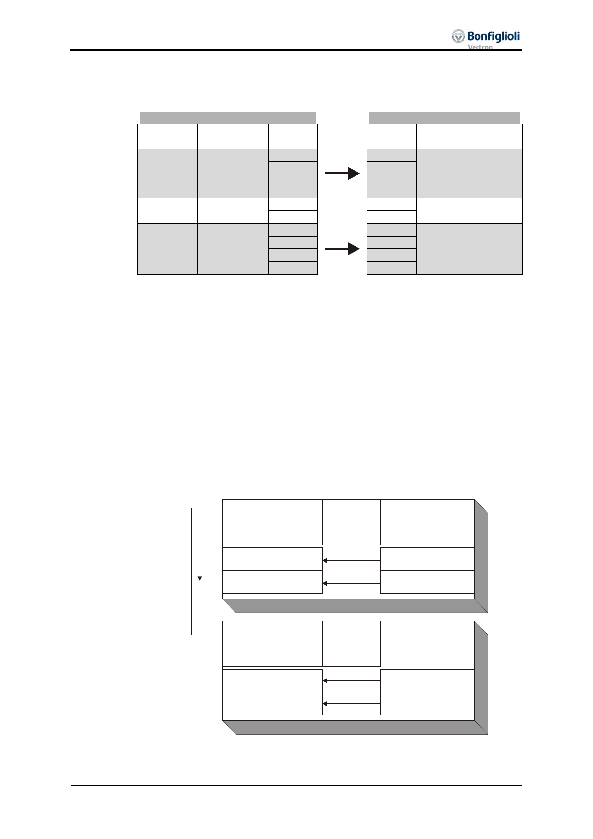
7.11.5.3 Examples of virtual links
Frequency inverter 1 Frequency inverter 2
Source
Control
2 2
3 3
Output
5 5
6 6
7 7
Parameter 950 = Source-No. 740 Parameter 99 = Source-No. 704
Parameter 955 = Source-No. 62 Parameter 137 = Source-No. 709
The control word of frequency inverter 1 is linked with the control word of frequency
As an extension, a number of frequency inverters can also exist on the receive side
The input link not used in the TxPDO1 of frequency inverter 1 is on ZERO and is thus
Example 1:
word
740
no.
Input link TxPDO1
Byte
950 0
1 1
RxPDO1
Byte
0 704 Control in-
Source
- No.
Target
put,
Control word
99
955 4
reference
frequency
4 709 Ramp input,
Line set
value 137
channel 62
inverter 2. In this way, both frequency inverters can be operated synchronously via
the remote control. The output of the reference value channel of frequency inverter 1
is laid onto the output of the ramp of frequency inverter 2. In this way, both frequency inverters have a joint source of reference values and are given reference values in
the internal notation.
(Rx), these then being supplied with data parallel and simultaneously.
not served.
Example 2:
Example of a virtual link with transmission via the system bus:
TxPDO1 Identifier
925
385
Inverter 1
Parameter
Identifier
system bus
TxPDO1 Boolean1
Parameter
RxPDO1 Identifier
Parameter
Sta rt-cloc kw ise
Parameter
924
068
946
385
Identifier
71-S2IND
Source-No.
Inverter 2
700-RxPDO1 Boolean
Source-No.
03/12 EM-ABS-01 for ACU 75

7.12 Control parameters
For the monitoring of the system bus and the display of the internal states, two con-
trol parameters are provided. There is a report of the system bus state and a report
of the CAN state via two actual value parameters.
Note: If the BUS-OFF state occurs, the frequency inverter breaks down with
After Bus-OFF, the system bus in the frequency inverter is completely reinitialized.
Actual values of the system bus
No. Description Display
978 Node state 1 - Pre-Operational
979 CAN state 1 - OKAY
Node State 978 parameter gives information about the Pre-Operational, Opera-
The
tional, Stopped state. A PDO transfer is only possible in the Operational state. The
state is controlled by the system bus master (PLC / PC / frequency inverter) via NMT
telegrams.
CAN-State 979 parameter gives information about the state of the physical
The
layer. If there are transmission errors, the state changes from OKAY to WARNING
until the cancellation of the communication with BUS-OFF. After BUS-OFF, the CAN
controller is automatically re-initialized and the system bus started again.
“F2210 BUS-OFF”.
There is a new boot-up message from the subscriber and an emergency telegram
with the Bus-OFF message is transmitted. The change of state of the subscriber to
Operational is done by the Start-Remote-Node telegram cyclically sent by the system
bus master.
2 - Operational
3 - Stopped
2 - WARNING
3 - BUS-OFF
76 EM-ABS-01 for ACU 03/12

7.13 Handling of the parameters of the system bus
As soon as the system bus extension module EM-SYS exists in a frequency inverter,
the actual value parameters for system state and bus state are activated and can be
observed in the actual value menu VAL of the control unit KP500 or with the VPlus
PC program in the menu Actual values \ System bus.
Note: The actual value parameters are on operation level 3 and are thus avail-
able for the user at any time.
All the setting parameters for the configuration of the system bus are not directly
accessible for the user. For defined customer applications, pre-defined XPI files can
be generated by VECTRON for the VPlus PC program, with which the necessary parameters are visible for the user. The application-relevant variables are then available
in these XPI files.
Note: XPI files can be read in addition to the loaded parameter information of
the frequency inverter into the VPlus PC program.
In the menu of the software under the point "Edit" you find the command "Read in XPI file".
The method of working via an XPI file has its reasoning in the fact that deep inter-
ventions in the system are possible via the system bus and can lead to serious problems in the application with an untrained user. Via the XPI files, a user is given a
selection list pre-defined by VECTRON.
Atten-
tion:
Experienced users have complete access to all the existing sources and possible input
links with the XPI file of the active functions. The selection depends on the selected
configuration and control procedure.
The configuration of the necessary parameters for the system bus is
accessible by a XPI file with the help of the VPlus PC program.
The control unit KP500 does not support this functionality.
If the extension module system bus EM-SYS is installed additionally to a
communication module for the field bus connection (CM-232, CM-485 or
CM-PDP) in the frequency inverter, the parameterization can be made
with the interface adapter KP232.
03/12 EM-ABS-01 for ACU 77

The display of the parameters when using the XPI file is according to the following
System bus
Basic Settings 900 Node-ID
903 Baud rate
Master Functions 904 Boot-up delay
919 SYNC-Time
SYNC identifier 918 SYNC identifier
SDO1-Identifier 921 RxSDO1 identifier
922 TxSDO1 identifier
SDO2 Set Active 923 SDO2 Set Active
PDO Identifier 924 RxPDO1 identifier
925 TxPDO1 identifier
926 RxPDO2 identifier
927 TxPDO2 identifier
928 RxPDO3 identifier
929 TxPDO3 identifier
TxPDO Function 930 TxPDO1 Function
931 TxPDO1 Time
932 TxPDO2 Function
933 TxPDO2 Tome
934 TxPDO3 Function
935 TxPDO3 Time
RxPDO Function 936 RxPDO1 Function
937 RxPDO2 Function
938 RxPDO3 Function
Timeout 939 SYNC timeout
941 RxPDO1 Timeout
942 RxPDO2 Timeout
945 RxPDO3 Timeout
TxPDO1 Objects 946 TxPDO1 Boolean1
947 TxPDO1 Boolean2
948 TxPDO1 Boolean3
949 TxPDO1 Boolean4
950 TxPDO1 Word1
951 TxPDO1 Word2
952 TxPDO1 Word3
953 TxPDO1 Word4
954 TxPDO1 Long1
955 TxPDO1 Long2
TxPDO2 Objects 956 TxPDO2 Boolean1
957 TxPDO2 Boolean2
958 TxPDO2 Boolean3
959 TxPDO2 Boolean4
960 TxPDO2 Word1
961 TxPDO2 Word2
962 TxPDO2 Word3
963 TxPDO2 Word4
964 TxPDO2 Long1
965 TxPDO2 Long2
TxPDO3 Objects 966 TxPDO3 Boolean1
967 TxPDO3 Boolean2
968 TxPDO3 Boolean3
969 TxPDO3 Boolean4
972 TxPDO3 Word1
973 TxPDO3 Word2
974 TxPDO3 Word3
975 TxPDO3 Word4
976 TxPDO3 Long1
977 TxPDO3 Long2
Actual values
System bus 978 Node state
979 CAN state
structure:
78 EM-ABS-01 for ACU 03/12

7.14 Ancillaries
For the planning of the system bus according to the drive tasks in question, there are
ancillaries in the form of tables.
The planning of the system bus is done in three steps:
1. Definition of the communication relationships
2. Production of the virtual links
3. Capacity planning of the system bus
The priority assignment of the identifiers is relevant for the definition of the commu-
nication relationships. Data that are to be transmitted with a higher priority must be
given low identifiers. This results in the message with the higher priority being
transmitted first with a simultaneous access of two subscribers to the bus.
Note: The recommended identifier range for the communication relationships
via the PDO channels is 385 ...
The identifiers below 385 are used for the NMT telegrams (boot-up se-
quence, SYNC telegram) and emergency message.
The identifiers above 1407 are used for the SDO channel for parameteri-
zation.
03/12 EM-ABS-01 for ACU 79

7.14.1 Definition of the communication relationships
The communication relationships are planned and documented with the help of the
table. The table is available as a Microsoft Word document "kbl.doc" on the VECTRON
product CD or upon request.
________
________
________
________
Node-ID:
________
Node-ID:
________
PDO Identifier
PDO Identifier
TxPDO1
RxPDO1
TxPDO2
RxPDO2
TxPDO3
RxPDO3
TxPDO1
RxPDO1
TxPDO2
RxPDO2
TxPDO3
RxPDO3
________
________
Inverter: Inverter: Inverter:Inverter:Inverter:
Node-ID:
________
Node-ID:
________
Node-ID:
PDO Identifier
PDO Identifier
PDO Identifier
TxPDO1
RxPDO1
TxPDO1
RxPDO1
TxPDO1
RxPDO1
TxPDO2
RxPDO2
TxPDO2
RxPDO2
TxPDO2
RxPDO2
TxPDO3
RxPDO3
TxPDO3
RxPDO3
TxPDO3
RxPDO3
80 EM-ABS-01 for ACU 03/12

7.14.2 Production of the virtual links
The virtual links are planned and documented with the help of the table. The table is
available as a Microsoft Word document "vvk.doc" on the VECTRON product CD or
upon request.
No.
Source-
________
: ___________________________
Inverter
Node-ID: ________
Identifier: ___________
RxPDO-No.:
(Tx/RxPDO)
Boolean uint/int long
Input Link/Parameter-No.
________
: ___________________________
Inverter
03/12 EM-ABS-01 for ACU 81
Node-ID: ________
TxPDO -No.:
Input Link/Pa rameter-No.
Source-
Boolean uint/int long
No.

7.14.3 Capacity planning of the system bus
Each PDO telegram possesses a constant useful data content of 8 Bytes. According to
worst case, this results in a maximum telegram length of 140 bits. The maximum
telegram run time of the PDOs is thus stipulated via the set baud rate.
Capacity planning
Baud rate
kBaud
1000 140
500 280
250 560
125 1120
100 1400
50 2800
As a function of the set baud rate and the transmission interval of the TxPDOs se-
lected, the following bus loads results:
Capacity of the system bus
Baud
1ms 2ms 3ms 4ms 5ms 6ms 7ms 8ms 9ms 10ms
rate /
Bus load as a function of the transmission for one TxPDO in %
kBaud
1.000 14 7 4,7 3,5 2,8 2,3 2 1,8 1,6 1,4
500 28 14 9,3 7 5,6 4,7 4 3,5 3,1 2,8
250 56 28 18,7 14 11,2 9,3 8 7 6,2 5,6
125 112 56 37,3 28 22,4 18,7 16 14 12,4 11,2
100 140 70 46,7 35 28 23,3 20 17,5 15,6 14
50 280 140 93,3 70 56 46,7 40 35 31,1 28
Atten-
tion:
A bus load >100% means that a telegram cannot be dispatched completely between two transmission times.
This observation must be done for each TxPDO. The sum of all the TxPDOs decides
on the entire bus load. The bus load must be designed in such a way that any telegram repetitions for transmission errors are possible without exceeding the bus capacity.
Note: To facilitate capacity planning, a Microsoft Excel file with the name
"Load_Systembus.xls” is available.
Telegram runtime
μs
Such a setting is not admissible!
82 EM-ABS-01 for ACU 03/12

The capacity planning are planned and documented with the help of the table. The
work sheet is available as a Microsoft Excel document "Load_Systembus.xls" on the
VECTRON product CD or by request.
Load system bus
Baud rate [kBaud]:
50, 100, 125, 250, 500, 1000
1000
Frequency
inverter
TxPDO
Number
Ta
[ms]
Workload
[%]
1 1 0 0
2 0 0
3 0 0
2 1 0 0
2 0 0
3 0 0
3 1 0 0
2 0 0
3 0 0
4 1 0 0
2 0 0
3 0 0
5 1 0 0
2 0 0
3 0 0
6 1 0 0
2 0 0
3 0 0
7 1 0 0
2 0 0
3 0 0
8 1 1 14
2 1 14
3 1 14
9 1 1 14
2 1 14
3 0 0
10 1 0 0
2 0 0
3 0 0
Total workload [%] 70
In the table, the set baud rate is entered from the parameter
kBaud. For each frequency inverter, the set time for the transmission interval (e. g.
TxPDO1 Time 931) in ms is entered for the TxPDO being used at the time. In the
column Load the bus load caused by the individual TxPDO appears, under Total
Load the entire bus load.
For the bus load (Total load) the following limits have been defined:
≤ 80 %
80 ... 90
%
> 90 %
03/12 EM-ABS-01 for ACU 83
Î OKAY
Î CRITICAL
Î NOT POSSIBLE
Baud Rate 903in

T
t
g
T
P
g
8 Control inputs and outputs
8.1 Analog input EM S1INA
8.1.1 General
The analog input of the EM-ABS-01 extension module can be used as a voltage input.
Parameterization of the input signal is done via the definition of a linear characteristic
and assignment as
− Reference value source
(selectable via parameter
− Reference percentage source
(selectable via parameter
− Actual percentage source
(selectable via parameter
or
− limit value sources
(can be selected via the parameters 734 … 737).
Reference frequency source 475),
Reference percentage source 476),
Actual percentage source 478, in configuration x11)
8.1.2 Characteristic
Mapping of the analog input signal onto a reference frequency value or a reference
percentage value is possible for various requirements. Parameterization is to be done
via two points of the linear characteristic of the reference value channel.
he characteristic point 1, with the coordinates X1 and Y1, and the characteristic poin
2, with the coordinates X2 and Y2, can be set in four parameters.
Points X1 and X2 are stated in per cent, as the analo
current or voltage input via switch S3.
Parameters Settings
No. Description Min. Max. Factory set-
564 Point X1 -100,00 % 100,00 % -98,00 %
565 Point Y1 -100,00 % 100,00 % -100,00 %
566 Point X2 -100,00 % 100,00 % 98,00 %
567 Point Y2 -100,00 % 100,00 % 100,00 %
he coordinates of the points relate, as a percentage, to the analog signal with 10 V
or 20 mA and parameter
Maximum Frequency 419 or parameter Maximum Reference
ercentage 519. The direction of rotation can be chan
frequency inverter and/or by selection of the points.
The definition of the analog input characteristic can be calculated via the two-point
form of the line equation. The speed Y of the drive is controlled ac-cording to the analog control signal X.
Y1-Y2
Y +−⋅=
()
X1-X2
Attention!
The monitoring of the analog input signal via parameter
behavior
Sensible use is only possible if
563 demands examination of the characteristic parameters.
Point X1 564 is in the positive range.
input can be switched as a
ting
ed via the digital inputs of the
Y1X1X
Error/Warning
84 EM-ABS-01 for ACU 03/12

g
r
f
T
g
g
T
Y
Y
T
V
8.1.3 Operation modes
The operation modes of the analog input characteristic enable application-related scal-
as a supplement to the characteristic points mentioned above. One of the fou
in
linear types of characteristic is selected for the signal adaptation for the analog input
signal via parameter
Operation mode 562. If the points are not suited for the type o
characteristic selected, they are corrected internally.
Operation mode 562
1 - bipolar
he analog input signal is mapped onto the reference
Function
value according to the points (X1/Y1) and (X2/Y2).
11 - unipolar With a negative parameter value of the points X1 or
X2, the latter are mapped to the reference value zero.
21 - unipolar 2-10V/4-20mA If the points X1 or X2 have been set with a negative
parameter value or less than 0%, the input characteristic is mapped to the reference value 20%.
101 - bipolar abs. Negative parameter values of the points Y1 or Y2 are
mapped as a positive reference value in the characteristic.
Further information on the operation modes stated in the table can be found in the
following chapter "Examples“.
8.1.3.1 Examples
The analog input signal is mapped onto a reference value as a function of the charac-
teristic selected. The followin
voltage signal. The parameter Minimum Frequency 418 has been set to the value
0.00 Hz. The characteristic point 100% for the Y axis corresponds to the parameter
Maximum Frequency 419 of 50.00 Hz in the examples.
Attention!
Operation mode "1 – bipolar"
In operation mode "1 – bipolar“, the characteristic of the analog input can be freely
set by stating two characteristic points.
(X1=-70% / Y1=-50%)
he various operation modes change the input characteristic as a
func-tion of the characteristic points parameterized. In the following examples, the areas of the system of coordinates from which a characteristic
point is displaced are marked.
Y
42.50Hz
-7V
(X2=80% / Y2=85%)
-25Hz
examples show the operation modes for an analo
Point 1:
X1 = -70.00% · 10 V = -7.00 V
1 = -50.00% · 50.00 Hz = -25.00 Hz
Point 2:
X2 = 80.00% · 10 V = 8.00 V
2 = 85.00% · 50.00 Hz = 42.50 Hz
X
8V
Tolerance band:
ΔX = 2.00% · 10 V = 0.20 V
he direction of rotation is changed in this
example at an analog input signal of -1.44
, with a tolerance band of ±0.20 V.
03/12 EM-ABS-01 for ACU 85

Y
Y
t
g
Y
Y
g
V
Operation mode "11 – unipolar"
In operation mode "11 – unipolar“, the characteristic points are displaced to the origin
of the characteristics with a negative value for the X axis.
42.50Hz
Y
(X2=8 0 % / Y2 = 8 5% )
Point 1:
X1 = -70.00% · 10 V = -7.00 V
1 = -50.00% · 50.00 Hz = -25.00 Hz
Point 2:
X2 = 80.00% · 10 V = 8.00 V
2 = 85.00% · 50.00 Hz = 42.50 Hz
8V
X
Tolerance band:
-7V
ΔX = 2.00% · 10 V = 0.20 V
-25Hz
(X1=-70% / Y1=-50%)
Point 1 has been shifted into the origin.
The parameter
Tolerance band 560 is no
taken into account in this example, as no
e of sign of the reference frequency
chan
value takes place.
42.50Hz
Y
(X2=80% / Y2=85%)
Point 1:
X1 = 30.00 % · 10 V = 3.00 V
1 = -50.00 % · 50.00 Hz = -25.00 Hz
-25.00Hz
3.00V
8.00V
(X1=30% / Y1=-50%)
X
Point 2:
X2 = 80.00 % · 10 V = 8.00 V
2 = 85.00 % · 50.00 Hz = 42.50 Hz
Tolerance band:
ΔX = 2.00 % · 10 V = 0.20 V
The direction of rotation is chan
ed in this
example at an analog input signal of 4.85
, with a tolerance band of ±0.20 V.
86 EM-ABS-01 for ACU 03/12

T
X
X
⋅
=
Y
Y
Y
Y
T
V
his operation mode limits the input characteristic to the area between 20% and
Operation mode “21 – unipolar 2-10V/4-20mA”
100% of the analog signal. If the value for a characteristic point of the X axis is outside 0%, it is mapped to the characteristic point (2 V / 0 Hz).
The characteristic point on the X axis is calculated according to the following formula:
Kennlinien +
42.50Hz
Parameterwpunkt
Y
(X2=8 0 % / Y2 = 8 5% )
Point 1:
X1 = [-70.00% · (100.00% - 20.00%)
+ 20.00% ] · 10 V = -7.60 V
20,00%20,00%)-(100,00%ert
1 = -50.00% · 50.00 Hz = -25.00 Hz
Point 2:
X2 = [80.00% · (100.00% - 20.00%)
-7.60V
8.40V
X
+ 20.00% ] · 10 V = 8.40 V
2 = 85.00% · 50.00 Hz = 42.50 Hz
Tolerance band:
-25.00Hz
(X1=-70% / Y1=-50%)
ΔX = [2.00% · (100.00% - 20.00%)
· 10 V] = 0.16 V
42.50Hz
-25.00Hz
Y
(X2=80% / Y2=85%)
4.40V
(X1=30% / Y1=-50%)
8.40V
The characteristic point 1 has been displaced to the point (2.00V / 0.00 Hz). The
parameter
Tolerance band 560 is not
taken into account in this example, as no
change of sign of the reference frequency
value takes place.
Point 1:
X1 = [30.00% · (100.00% - 20.00%)
+ 20.00% ] · 10 V = 4.40 V
1 = -50.00% · 50.00 Hz = -25.00 Hz
Point 2:
X2 = [80.00% · (100.00% - 20.00%)
X
+ 20.00% ] · 10 V = 8.40 V
2 = 85.00% · 50.00 Hz = 42.50 Hz
Tolerance band:
ΔX = [2.00% · (100.00% - 20.00%)
· 10 V] = 0.16 V
he direction of rotation is changed in this
example at an analog input signal of 5.88
, with a tolerance band of ±0.16 V.
03/12 EM-ABS-01 for ACU 87

Y
Y
f
g
t
T
g
g
f
g
g
Operation mode "101 – bipolar Amount"
The operation mode "101 – bipolar Amount“ maps the bipolar analog signal onto a
unipolar input characteristic. The formation of the absolute amount takes the characteristic into account comparable to the "bipolar" operation mode, but the characteristic
points are reflected on the X axis with a negative value for the Y axis.
-7V
42.50Hz
25.00Hz
Y
(X2=80% / Y2=85%)
8V
Point 1:
X1 = -70.00% · 10 V = -7.00 V
1 = -50.00% · 50.00 Hz = -25.00 Hz
Point 2:
X2 = 80.00% · 10 V = 8.00 V
2 = 85.00% · 50.00 Hz = 42.50 Hz
X
Tolerance band:
ΔX = 2.00% · 10 V = 0.20 V
-25.00Hz
(X1=-70% / Y1=-50%)
In this example, the reference value is
again increased from an analog input signal of -1.44 V with a tolerance band o
±0.20 V. The theoretical chan
e of sign of
the reference value is taken into accoun
and leads to the tolerance band stated.
here is no change of the direction of
rotation.
8.1.4 Scaling
The analog input signal is mapped to the freely configurable characteristic. The maxi-
mum admissible settin
limits or percenta
of a bipolar characteristic, the minimum and maximum limits for both directions o
rotation are taken on. The percentage values of the points relate to the maximum
limits selected.
Parameters Settings
No. Description Min. Max. Factory set-
418 Minimum frequency 0.00 Hz 999.99 Hz 3.50 Hz
419 Maximum frequency 0.00 Hz 999.99 Hz 50.00 Hz
The control system uses the maximum value of the output frequency, which is calcu-
lated from the
Maximum Frequency 419 and the compensated slip of the drive me-
chanism. The frequency limits define the speed ran
values supplement the scalin
the functions configured.
Parameters Settings
No. Description Min. Max. Factory set-
518 Minimum percentage 0,00% 300,00% 0,00%
519 Maximum percentage 0,00% 300,00% 100,00%
range of the drive mechanism is to be set via the frequency
e limits according to the configuration selected. In parameterization
ting
e of the drive, and the percentage
of the analog input characteristic in accordance with
ting
88 EM-ABS-01 for ACU 03/12

T
g
g
g
t
8.1.5 Tolerance Band and Hysteresis
Parameters Settings
No. Description Min. Max. Factory set-
560 Tolerance band 0,00% 25,00% 2,00%
he analog input characteristic with change of sign of the reference value can be
adapted by the parameter
to be defined extends the zero crossin
Tolerance band 560 of the application. The tolerance band
of the speed relative to the analog control
signal. The parameter value (percent) is relative to the maximum current or volta
signal.
ting
pos. max. value
(X2/Y2)
pos. max. value
(X2 / Y2)
e
-10V
(-20mA)
(X1 / Y1)
Without tolerance band
The default
Minimum Frequency 418 or Minimum Percentage 518 extends the pa-
neg. max. value
+10V
(+20mA)
-10V
(-20mA)
(X1/Y1)
With tolerance band
+10V
Tolerance band
neg. max. value
rameterized tolerance band to the hysteresis.
pos. max. value
pos. min. value
neg. min. value
(X1 / Y1)
(X2/Y2)
Tolerance band
neg. max. value
With tolerance band and minimum value
For example, the output variable coming from positive input signals is kept on the
positive minimum value until the input si
nal becomes lower than the value for the
tolerance band in the negative direction. Then, the output variable follows the se
characteristic.
03/12 EM-ABS-01 for ACU 89

T
g
g
g
E
8.1.6 Error and warning behavior
0 - Off The input signal is not monitored.
Monitoring of the analog input signal is active regardless of the release of the
In operation mode 2, the drive mechanism is decelerated according to stopping beha-
Operation mode 3 defines free coasting of the drive, regardless of the stopping beha-
Attention!
he monitoring of the analog input signal necessary according to the application is
configured via the parameter
Error/warning behavior 563
1 - Warning < 1V/2mA
Error/Warning Behavior 563 .
Function
If the input signal is lower than 1 V, a warning
message is issued.
If the input signal is lower than 1 V, a warning
2 - Shut Down < 1V/2mA
message is issued; the drive is decelerated according to stopping behavior 1.
Error switch-off
3 -
< 1V/2mA
If the input signal is smaller than 1 V, there is a
warning and fault message and the drive mechanism stops freely.
fre-quency inverter according to the operation mode selected.
vior 1 (stop and shutdown) regardless of the stoppin
Operation mode 630). If the set holdin
Repeat startin
of the drive mechanism is possible by switching the start signal on and
time has expired, an error message is issued.
behavior selected (Parameter
off if the error has already been corrected.
vior selected defined in parameter
The monitoring of the analog input signal via parameter
behavior
563 demands examination of the characteristic parameters.
Stopping behavior 630.
rror/Warning
90 EM-ABS-01 for ACU 03/12

j
g
j
T
8.1.7 Adjustment
Due to component tolerance, it can be necessary to adjust the analog input. This is
done via parameter
Adjustment 568
0 - No adjustment Standard operation
1 - Adjustment 0 V
2 - Adjustment 10 V
Example of the adjustment of an analog input with a voltage signal:
Note: The measurements for the ad
measuring instrument and the correct polarity.
If not, faulty measurements can result.
• Apply 0 V to the analog input; e.g. with a bridge from the terminal of the ana-
• Select operation mode “1 - Adjustment 0 V”.
log input X410A.6 to terminal X210B.7 (earth/GND) of the frequency inverter.
• Apply 10 V to the analo
analog input to terminal X210B.5 (reference output 10 V) of the frequency inverter.
• Select operation mode “2 - Ad
of the analog input.
Adjustment 568.
Function
Adjustment of the measurement with an analog signal
of 0 V.
Adjustment of the measurement with an analog signal
of 10 V.
ustment are to be done with a suitable
input, e.g. with a bridge from the terminal of the
ustment 10 V”. This completes the adjustment
8.1.8 Filter time constant
The time constant of the filter for the reference analog value can be set via the para-
meter
Filter time constant 561.
he time constant indicates the time during which the input signal is averaged by
means of a low pass filter, e.g. in order to eliminate fault effects.
The setting range is between 0 ms and 5000 ms in 15 steps.
Filter time constant 561
0 - Time constant 0 ms
Filter deactivated – analog reference value is for-
warded unfiltered
2 - Time constant 2 ms Filter activated – averaging of the input signal via
4 - Time constant 4 ms
8 - Time constant 8 ms
the set value of the filter time constants Factory
setting: 8 ms.
16 - Time constant 16 ms
32 - Time constant 32 ms
64 - Time constant 64 ms
128 - Time constant 128 ms
256 - Time constant 256 ms
512 - Time constant 512 ms
1000 - Time constant 1000 ms
2000 - Time constant 2000 ms
3000 - Time constant 3000 ms
4000 - Time constant 4000 ms
5000 - Time constant 5000 ms
Function
03/12 EM-ABS-01 for ACU 91

T
g
8.2 Digital outputs EM-S1OUTD and EM-S2OUTD
8.2.1 General
Parameterization of the digital outputs permits a linking to a variety of functions. The
selection of the functions depends on the parameterized configuration.
8.2.2 Operation modes
The operation mode of digital output EM-S1OUTD (Terminal X410A.3) is done via pa-
rameter
Open brake”.
The operation mode of digital output EM-S1OUTD (Terminal X410A.4) is done via parameter
Off”.
he operation modes to be selected correspond to the table shown in the operatin
instructions of the frequency inverter in the chapter "Digital outputs“.
Operation mode EM-S1OUTD 533. By default, this parameter is set to “41 -
Operation mode EM-S2OUTD 534. By default, this parameter is set to “0 -
8.2.3 Repetition frequency output via EM-S1OUTD and EM-S2OUTD
0 - Off Reference frequency output is turned off.
1 - On The repetition frequency output via digital
Digital outputs EM-S1OUTD and EM-S2OUTD can be used as repetition frequency outputs. The output value of the repetition frequency output corresponds to the mechanical frequency of the connected encoder.
Digital outputs EM-S1OUTD and EM-S2OUTD can be set up as a repetition frequency
output via parameter
Repetition frequency EM-S1/2OUTD
Repetition frequency EM-S1/2OUTD 509.
Function
509
Factory setting.
outputs EM-S1OUTD and EM-S2OUTD is
turned on. The number of division marks of
the repetition frequency output corresponds
to the number of encoder division marks (set
via
Division marks 1183, see chapter 8.4.1).
92 EM-ABS-01 for ACU 03/12

g
g
A
F
F
F
F
F
F
F
F
F
F
8.3 Digital inputs EM-SxIND
The EM-ABS-01 extension module has three digital inputs. The assignment of the con-
trol si
question. Depending on the
selection of the operation mode differ. In addition to the available digital control inputs, further internal logic signals are available as sources.
The individual software functions are assigned to the various signal sources via para-
meterizable inputs. This enables a flexible use of the digital control signals.
Operation mode Function
320 - EM-S1IND Signal on digital input 1 (X410B.2)
321 - EM-S2IND Signal on digital input 2 (X410B.3)
322 - EM-S3IND Signal on digital input 3 (X410B.4)
520 - EM-S1IND inverted Inverted signal on digital input 1 (X410B.2)
521 - EM-S2IND inverted Inverted signal on digital input 2 (X410B.3)
522 - EM-S3IND inverted Inverted signal on digital input 3 (X410B.4)
frequency inverter in the chapter "Digital inputs" also apply.
nals to the available software functions can be adapted to the application in
Configuration 30 selected, the default assi
longside the operation modes listed, those stated in the operating instructions of the
nment or the
8.3.1 Fixed reference value and fixed value change-over
Depending on the
used as reference values. The module extends the functionality described in the frequency inverter user manual (Parameters
ixed frequency change-over 2 67) by parameter Fixed frequency change-over 3 131
and the corresponding parameters Fixed frequency 5 485, Fixed frequency 6 486,
ixed frequency 7 487, Fixed frequency 8 488.
ixed frequency 1 480
ixed frequency 2 481
ixed frequency 3 482
ixed frequency 4 483
ixed frequency 5 485
ixed frequency 6 486
ixed frequency 7 487
ixed frequency 8 488
Reference Frequency Source 475 selected, fixed frequencies can be
Fixed frequency change-over 1 66 and
Fixed frequency
change-over 1
66
0 0 0
1 0 0
1 1 0
0 1 0
0 1 1
1 1 1
1 0 1
0 0 1
Fixed frequency
change-over 2
Fixed frequency
change-over 3
67
131
03/12 EM-ABS-01 for ACU 93

g
g
E
D
r
g
8.4 Encoder input EM-ABS-01
The encoder input is used for evaluating the position information from the encoder.
Dependin
following table describes the use of the individual parameters for the encoder systems.
Parameters Encoder system
No. Description SinCos Hiperface EnDat 2.1 SSI
513 EC2 Gear Factor Numerator X X X X
514 EC2 Gear Factor Denominator X X X X
1183 Division marks X X X (X)
1184 Encoder signals/log X X X X
1186 Power supply X X X X
1187 Supply voltage X X X X
1188 Offset 1)
1268 SSI: Sampling interval --- --- --- X
1269 SSI: Error-/Extra-Bits (Low) --- --- --- X
1270 SSI: Error-/Extra-Bits (High) --- --- --- X
1271 Bits/Turn --- X --- X
1272 Bits Multiturn --- X --- X
X: Parameter must be configured according to the encoder data sheet.
--- Parameter has no function for this encoder type.
(X): In the case of SSI encoders the evaluation of the division marks depends on the
1): Setting the offset is required in the case of synchronous motors.
In addition, the following actual value parameters are available:
Parameters Encoder system
No. Description SinCos Hiperface EnDat 2.1 SSI
1267 Abs. encoder raw data --- X X X
1274 Warning Dig. Encoder --- --- X ---
Note: If positionin
Note:
on the encoder system used, certain parameters need to be set up. The
setting of
Tracks/Protocol 1184.
(configurations x40) is used, please note to the instructions
in chapter
Gear factors EC2 Gear Factor Numerator 513 and
enominato
8.4.11.1.
C2 Gear Factor
514 are not available in configurations 5xx.
8.4.1 Division marks
Parameters Settings
1183 Division marks 0 8192 1024
94 EM-ABS-01 for ACU 03/12
In parameter Division marks 1183, you can set the type-specific number of division
marks of the encoder. The number of division marks is typically described in amplitudes/revolution in the case of encoders with SinCos tracks. Enter the division marks or
amplitudes/revolution in parameter
Division marks 1183.
No. Description Min. Max. Factory set-
ting
Note:
In the case of SSI absolute value encoders, evaluation of Division marks
1183 is active only if Tracks/Protocol 1184 is described in an operation
mode for evaluation of TTL [RS-422] or SinCos tracks (settin
s 51xx,
59xx, 61xx and 69xx).

V
f
T
8.4.2 Tracks/Protocol
Key of Tracks/Protocol:
ia parameter Tracks/Protocol 1184, you can specify the type-specific number o
analog Tracks/Protocol of the encoder and evaluation of a reference track.
Note:
he identifiers of track A/B and Sin/Cos are typically ambivalent and can
be set to A = Sin and B = Cos.
Tracks/Protocol 1184
Function
0 - off Evaluation is turned off. Factory setting.
SinCos 100 - A/B Evaluation of analog Tracks/Protocol A and B.
300 - A/B, C/D
500 - A/B, R
700 - A/B, C/D, R
Evaluation of analog Tracks/Protocol A and B and commutation Tracks/Protocol C and D.
Evaluation of analog Tracks/Protocol A and B as well as reference track R. Monitoring and comparison of Tracks/Protocol.
Evaluation of analog Tracks/Protocol A and B and commutation Tracks/Protocol C/E as well as reference track R. Monitoring and comparison of Tracks/Protocol.
EnDat 2.1
1101 EnDat 2.1
Evaluation of analog Tracks/Protocol A/B and the data and
clock track with the EnDat 2.1 protocol. Monitoring and comparison of Tracks/Protocol.
Hiperface
Hiperface,
3109
9.6 kBit/s
Hiperface,
3119
19.2 kBit/s
Hiperface,
3138
38.4 kBit/s
Evaluation of analog Tracks/Protocol A/B and the data tracks
with the Hiperface protocol. Monitoring and comparison of
Tracks/Protocol. The data track is transmitted at 9.6 kBaud.
Like 3109. The data track is transmitted at 19.2 kBaud.
Like 3109. The data track is transmitted at 38.4 kBaud.
03/12 EM-ABS-01 for ACU 95

SSI
Gray code
SSI
Binary code
Tracks/Protocol 1184
SSI, Gray code,
5001
141 kBit/s
SSI, Gray code,
5002
281 kBit/s
SSI, Gray code,
5005
563 kBit/s
SSI, Gray code,
5011
1125 kBit/s
SSI+SINCOS, Gray
5101
code, 141 kBit/s
SSI+SINCOS, Gray
5102
code, 281 kBit/s
SSI+SINCOS, Gray
5105
code, 563 kBit/s
SSI+SINCOS, Gray
5111
code, 1125 kBit/s
SSI+TTL, Gray
5901
code, 141 kBit/s
SSI+TTL, Gray
5902
code, 281 kBit/s
SSI+TTL, Gray
5905
code, 563 kBit/s
SSI+TTL, Gray
5911
code, 1125 kBit/s
SSI, binary code,
6001
141 kBit/s
SSI, binary code,
6002
281 kBit/s
SSI, binary code,
6005
563 kBit/s
SSI, binary code,
6011
1125 kBit/s
SSI+SINCOS,
6101
binary code, 141
kBit/s
SSI+SINCOS,
6102
binary code, 281
kBit/s
SSI+SINCOS,
6105
binary code, 563
kBit/s
SSI+SINCOS,
6111
binary code, 1125
kBit/s
SSI+TTL, binary
6901
code, 141 kBit/s
SSI+TTL, binary
6902
code, 281 kBit/s
Function
Evaluation of data and clock tracks with the SSI protocol
(without TTL or SinCos track). The data track is transmitted at
140.625 kBaud in Gray code.
ing prepared
Like 5001. The data track is transmitted at 281.25 kBaud in
Gray code.
Like 5001. The data track is transmitted at 562.5 kBaud in
Gray code.
Like 5001. The data track is transmitted at 1125 kBaud in Gray
code.
Evaluation of Tracks/Protocol A/B as SINCOS track and the
data and clock tracks with the SSI protocol. The data track is
transmitted at 140.625 kBaud in Gray code.
Like 5101. The data track is transmitted at 281.25 kBaud in
Gray code.
Like 5101. The data track is transmitted at 562.5 kBaud in
Gray code.
Like 5101. The data track is transmitted at 1125 kBaud in Gray
code.
Evaluation of Tracks/Protocol A/B as TTL [RS-422] track and
the data and clock tracks with the SSI protocol. The data track
is transmitted at 140.625 kBaud in Gray code.
Like 5901. The data track is transmitted at 281.25 kBaud in
Gray code.
Like 5901. The data track is transmitted at 562.5 kBaud in
Gray code.
Like 5901. The data track is transmitted at 1125 kBaud in Gray
code.
Evaluation of data and clock tracks with the SSI protocol
(without TTL or SinCos track). The data track is transmitted at
140.625 kBaud in binary code.
being prepared
Like 6001. The data track is transmitted at 281.25 kBaud in
binary code.
Like 6001. The data track is transmitted at 562.25 kBaud in
binary code.
Like 6001. The data track is transmitted at 1125 kBaud in binary code.
Evaluation of Tracks/Protocol A/B as SINCOS track and the
data and clock tracks with the SSI protocol. The data track is
transmitted at 140.625 kBaud in binary code.
Like 6101. The data track is transmitted at 281.25 kBaud in
binary code.
Like 6101. The data track is transmitted at 562.25 kBaud in
binary code.
Like 6101. The data track is transmitted at 1125 kBaud in binary code.
Evaluation of Tracks/Protocol A/B as TTL [RS-422] track and
the data and clock tracks with the SSI protocol. The data track
is transmitted at 140.625 kBaud in binary code.
Like 6901. The data track is transmitted at 281.25 kBaud in
binary code.
!
!
This function is currently be-
This function is currently
96 EM-ABS-01 for ACU 03/12

g
f
g
g
A
Tracks/Protocol 1184
SSI+TTL, binary
6905
code, 563 kBit/s
SSI+TTL, binary
6911
code, 1125 kBit/s
Note: For synchronous servomotors, an encoder with commutation track or
Note:
Note for SSI
encoders:
Function
Like 6901. The data track is transmitted at 562.25 kBaud in
binary code.
Like 6901. The data track is transmitted at 1125 kBaud in binary code.
absolute value will be required. Settin
s 100 and 500 are only intended
for operation with asynchronous motors for this reason. In the case o
synchronous servomotors, set the
Offset 1188 accordin
to chapter
8.4.6.
Changeover of parameter Tracks/Protocol 1184 can only be done with
the output stage disabled. After the parameter chan
e, the new encoder
type will have to be initialized. This may take up to 5 seconds.
fter mains on, an initialization may have to be performed depending on
the encoder type. This may take up to 5 seconds.
The usable transmission rate depends on the length of the encoder cable. In case there are any transmission errors, reduce the transmission
rate.
03/12 EM-ABS-01 for ACU 97

V
g
g
g
r
8.4.3 Power supply
ia parameter Power supply 1186, you can choose the encoder power supply source.
Dependin
on the power demand of the encoder, you can connect an external power
supply to terminals X410A.1 and X410A.2 (see Chapter
case, parameter
Sense”.
The operation modes with meas. line “sense” (
Sense” or “6 – Via X410A, Sense”) enable monitoring of the supply voltage of the encoder. In these settin
encoder deviates from the set volta
end of the supply line (at encoder).
In operation modes 1 and 2, the voltage is controlled at the EM-ABS-01 module, powe
losses during energy transmission via the supply line will not be compensated.
The encoder can be powered as follows:
− via control terminals X410A.5 (5 … 12 VDC) and X410A.7 (GND) or
− via contacts X412.6 (V
See chapters 5.3.2 “Control terminals” and 5.3.3 “Power supply”.
Caution!
0 - off
1 - Intern
Via
2 -
X410A
intern,
5 -
Sense
Via
6 -
X410A,
Sense
Note:
Even if the encoder features a measuring line “sense”, you can chose operation
mode 1 or 2.
5.3.3 “Power supply”). In this
Power supply 1186 must be set to “2 – Via X410A” or “6 – Via X410A,
Power supply 1186 = “5 – intern,
s, deviations will be compensated when the supply voltage of the
e level. To that end, the voltage is measured at the
) and X412.15 (0VL) of the female HD-Sub-D connector.
Enc
Always set the Supply voltage 1187 first, then set Power supply 1186.
Otherwise, the encoder might be destroyed by high voltage levels.
Power supply 1186
No power supply selected for the encoder. This setting is also used if the
encoder is connected directly to an external power supply.
.
ting
power supply to encoder
− at terminals X410A.5 (5 … 12 VDC) and X410A.7 (GND)
− at contacts X412.6 (V
: 5 … 12 VDC) and X412.15 (0VL).
Enc
Voltage source is provided internally by the frequency inverter, max. 2 W.
power supply to encoder
− at terminals X410A.5 (5 … 12 VDC) and X410A.7 (GND)
− at contacts X412.6 (V
: 5 … 12 VDC) and X412.15 (0VL).
Enc
Power supply is effected through an external power source which must be
connected to terminals X410A.1 (24 VDC) and X410A.2 (ground).
power supply to encoder
− at terminals X410A.5 (5 … 12 VDC) and X410A.7 (GND)
− at contacts X412.6 (V
: 5 … 12 VDC) and X412.15 (0VL).
Enc
Voltage source is provided internally by the frequency inverter, max. 2 W.
A measuring line “sense” of the encoder must be connected in order to
monitor the supply voltage.
power supply to encoder
− at terminals X410A.5 (5 … 12 VDC) and X410A.7 (GND)
− at contacts X412.6 (V
: 5 … 12 VDC) and X412.15 (0VL).
Enc
Power supply is effected through an external power source which must be
connected to terminals X410A.1 (24 VDC) and X410A.2 (ground). A measuring line “sense” of the encoder must be connected in order to monitor
the supply voltage.
Factory set-
98 EM-ABS-01 for ACU 03/12

T
“
Note:
In the case of Hiperface encoders, the sense line (settings “5-intern, Sense” or “6-Via
X410A, sense“) is typically not used, as it is not defined in the Hiperface standard Specification. Thus, using the sense line is not required in the case of Hiperface encoders.
Note:
he maximum voltage of the power supply is DC 12 V. Via a sense line, the voltage can
be monitored at the encoder, but the voltage output is limited to DC 12 V.
The voltage level can be set up via parameter Supply voltage 1187. See chapter 8.4.4
Supply voltage”.
03/12 EM-ABS-01 for ACU 99

t
Note:
BONFIGLIOLI VECTRON recommends connecting an external power supply to the voltage
input of the control terminal. This auxiliary voltage enables powering an encoder via the
voltage output of the control terminal. Refer to the encoder manufacturer's power specifications.
Choosing the source for encoder power supply and setting the voltage level
Measuring line “sense”: constant voltage level at encoder
M
G
0VL
Sense
15
11
6
5 ... 12 VDC
Measured voltage
G: encoder
The encoder supply voltage is measured at the SinCos encoder and kept constant a
the adjusted value of Supply voltage 1187 (DC 5 … 12 V).
100 EM-ABS-01 for ACU 03/12
 Loading...