

BONFIGLIOLI ACTIVE CUBE 201, ACTIVE CUBE 501, ACTIVE CUBE 401, ACTIVE CUBE 601 Operating Instructions Manual

ACTIVE CUBE
Operating Instructions
Frequency inverter 230 V / 400 V
0.25 kW ... 132 kW


12/16
Operating Instructions ACU
3
TABLE OF CONTENTS
1 General Information about the Documentation .......................................................... 11
1.1 Instruction Manuals ......................................................................................... 11
1.2 This document .................................................................................................. 12
1.3 Warranty and liability ....................................................................................... 13
1.4 Obligation ......................................................................................................... 13
1.5 Copyright .......................................................................................................... 14
1.6 Storage ............................................................................................................. 14
2 General safety instructions and information on use .................................................... 15
2.1 Terminology ...................................................................................................... 15
2.2 Designated use ................................................................................................. 15
2.3 Misuse ............................................................................................................... 16
2.3.1 Explosion protection ................................................................................................. 16
2.4 Residual risks ................................................................................................... 16
2.5 Safety and warning signs on frequency inverter ............................................. 16
2.6 Warning information and symbols used in the Operating Instructions ........... 17
2.6.1 Hazard classes ......................................................................................................... 17
2.6.2 Hazard symbols ........................................................................................................ 17
2.6.3 Prohibition signs ....................................................................................................... 17
2.6.4 Personal safety equipment ........................................................................................ 18
2.6.5 Recycling ................................................................................................................. 18
2.6.6 Grounding symbol .................................................................................................... 18
2.6.7 ESD symbol .............................................................................................................. 18
2.6.8 Information signs ..................................................................................................... 18
2.6.9 Font style in documentation ...................................................................................... 18
2.7 Directives and guidelines to be adhered to by the operator ............................ 19
2.8 Operator's general plant documentation ......................................................... 19
2.9 Operator's/operating staff's responsibilities ................................................... 19
2.9.1 Selection and qualification of staff ............................................................................. 19
2.9.2 General work safety .................................................................................................. 19
2.9.3 Ear protectors .......................................................................................................... 19
2.10 Organizational measures .................................................................................. 20
2.10.1 General .................................................................................................................... 20
2.10.2 Use in combination with third-party products ............................................................. 20
2.10.3 Handling and installation ........................................................................................... 20
2.10.4 Electrical connections ................................................................................................ 20
2.10.4.1 The five safety rules ..........................................................................................20
2.10.5 Safe operation .......................................................................................................... 21
2.10.6 Maintenance and service/troubleshooting ................................................................... 22
2.10.7 Final decommissioning .............................................................................................. 22
2.11 Safety Instructions on Function “Safe Torque Off” (STO) ............................... 23
3 Storage and transport .................................................................................................. 24
3.1 Storage ............................................................................................................. 24
3.2 Special safety instructions on transport of heavy frequency inverters ........... 24
3.3 Dimensions/weight .......................................................................................... 25

4
Operating Instructions ACU
12/16
3.4 Transfer to place of installation ....................................................................... 25
3.5 Unpacking the device ....................................................................................... 25
3.6 Bringing the device into installation position .................................................. 25
3.6.1 Sizes 1 through 6 ..................................................................................................... 25
3.6.2 Sizes 7 and 8 ........................................................................................................... 25
4 Scope of supply ............................................................................................................ 27
4.1 Sizes 1 and 2: ACU 201 (up to 3.0 kW) and 401 (up to 4.0 kW) ...................... 27
4.2 Sizes 3 and 4: ACU 201 (4.0 to 9.2 kW) and 401 (5.5 to 15.0 kW) .................. 28
4.3 Size 5 ACU 401 (18.5 to 30.0 kW) .................................................................... 29
4.4 Size 6 ACU 401 (37.0 to 65.0 kW) .................................................................... 30
4.5 Size 7 ACU 401 (75.0 to 132.0 kW) .................................................................. 31
5 Technical data .............................................................................................................. 32
5.1 General technical data...................................................................................... 32
5.2 Technical Data – Control Electronic Equipment ............................................... 33
5.3 ACU 201 Size 1 (0.25 to 1.1 kw, 230 V) ........................................................... 35
5.4 ACU 201 Size 2 (1.5 to 3.0 kW, 230 V) ............................................................. 36
5.5 ACU 201 sizes 3 and 4 (4.0 to 9.2 kW, 230 V) .................................................. 37
5.6 ACU 401 Size 1 (0.25 to 1.5 kW, 400 V) ........................................................... 38
5.7 ACU 401 Size 2 (1.85 to 4.0 kW, 400 V) ........................................................... 39
5.8 ACU 401 sizes 3 and 4 (5.5 to 15.0 kW, 400 V) ................................................ 40
5.9 ACU 401 Size 5 (18.5 to 30.0 kW, 400 V) ......................................................... 41
5.10 ACU 401 Size 6 (37.0 to 65.0 kW, 400 V) ......................................................... 42
5.11 ACU 401 Size 7 (75.0 to 132.0 kW, 400 V) ....................................................... 43
5.12 Operation diagrams .......................................................................................... 44
6 Mechanical installation ................................................................................................ 46
6.1 Air circulation ................................................................................................... 46
6.2 Sizes 1 and 2: ACU 201 (up to 3.0 kW) and 401 (up to 4.0 KW) ...................... 46
6.3 Sizes 3 and 4: ACU 201 (4.0 to 9.2 kW) and 401 (5.5 to 15.0 kW) .................. 48
6.4 Size 5: ACU 401 (18.5 to 30.0 kW) ................................................................... 49
6.5 Size 6: ACU 401 (37.0 to 65.0 kW) (air-cooled) ............................................... 50
6.6 Size 7: ACU 401 (75.0 to 132.0 kW) ................................................................. 51
7 Electrical installation .................................................................................................... 52
7.1 EMC information ............................................................................................... 54
7.2 Block diagram ................................................................................................... 56
7.3 Optional components ....................................................................................... 57
7.4 Connection of Unit ............................................................................................ 58
7.4.1 Dimensioning of conductor cross-section .................................................................... 58
7.4.1.1 Typical cross-sections Size 1 through 7 (0.25 kW … 132 kW) ...............................58
7.4.2 Mains connection ...................................................................................................... 60
7.4.3 Motor connection ...................................................................................................... 60

12/16
Operating Instructions ACU
5
7.4.3.1 Length of motor cables, without filter..................................................................61
7.4.3.2 Motor cable length, with output filter dU/dt .........................................................61
7.4.3.3 Motor cable length, with sinus filter ....................................................................61
7.4.3.4 Group drive .......................................................................................................61
7.4.3.5 Speed sensor connection ....................................................................................61
7.4.4 Connection of a braking resistor ................................................................................ 62
7.5 Connection by size ............................................................................................ 63
7.5.1 Sizes 1 and 2: ACU 201 (up to 3.0 kW) and 401 (up to 4.0 kW) .................................. 63
7.5.2 Sizes 3 and 4: ACU 201 (4.0 to 9.2 kW) and 401 (5.5 to 15.0 kW) ............................... 65
7.5.3 Size 5 ACU 401 (18.5 to 30.0 kW) ............................................................................. 67
7.5.4 Size 6 ACU 401 (37.0 to 65.0 kW) ............................................................................. 69
7.5.5 Size 7 ACU 401 (75.0 to 132.0 kW)............................................................................ 71
7.6 Control terminals .............................................................................................. 73
7.6.1 External DC 24 V power supply ................................................................................. 75
7.6.2 Relay output ............................................................................................................ 75
7.7 X13 connection in ACU 501 and ACU 601 ........................................................ 76
7.7.1 Motor Thermo-Contact .............................................................................................. 76
7.7.2 Control terminals – Wiring diagrams of configurations ................................................ 76
7.8 Configurations overview .................................................................................. 77
7.8.1 Configuration 110 – Sensorless Control ...................................................................... 78
7.8.2 Configuration 111 – Sensorless Control with Technology Controller ............................. 78
7.8.3 Configuration 410 – Sensorless Field-Oriented Control ................................................ 79
7.8.4 Configuration 411 –Sensorless Field-Oriented Control with Technology Controller ......... 79
7.8.5 Configuration 430 – Sensorless Field-Oriented Control, speed and torque controlled ..... 80
7.8.6 Configuration 210 – Field-Oriented Control, Speed Controlled ...................................... 81
7.8.7 Configuration 211 – Field-Oriented Control with Technology Controller ........................ 82
7.8.8 Configuration 230 – Field-Oriented Control,Speed and Torque Controlled ..................... 82
7.8.9 Configuration 510 – Field-Oriented Control of Synchronous Machine, Speed Controlled . 83
7.8.10 Configuration 511 –Field-Oriented Control of Synchronous Machine with Technology
Controller ................................................................................................................. 84
7.8.11 Configuration 530 – Field-Oriented Control of a Synchronous Machine Speed and Torque
Controlled ................................................................................................................ 84
7.8.12 Configuration 610 – Sensorless Field-Oriented Control of Synchronous Machine, Speed
Controlled ................................................................................................................ 85
7.8.13 Configuration 611 – Sensorless Field-Oriented Control of Synchronous Machine with
Technology Controller ............................................................................................... 85
7.8.14 Configuration 630 – Sensorless Field-Oriented Control of a Synchronous Machine Speed
and Torque Controlled .............................................................................................. 86
7.9 Notes on installation as per UL508c ................................................................. 86
8 Control unit KP500 ....................................................................................................... 87
8.1 Menu structure ................................................................................................. 88
8.2 Main Menu ........................................................................................................ 88
8.3 Actual Value Menu (VAL) .................................................................................. 89
8.4 Parameter Menu (PARA) .................................................................................. 90
8.5 Copy Menu (CPY) .............................................................................................. 91
8.5.1 Reading the Stored Information ................................................................................ 91
8.5.2 Menu structure ......................................................................................................... 91
8.5.3 Selecting the Source ................................................................................................. 92
8.5.4 Selecting the Destination .......................................................................................... 92
8.5.5 Copy Operation ........................................................................................................ 93
8.5.6 Error messages ........................................................................................................ 93
8.6 Reading Data From Control Unit ...................................................................... 94

6
Operating Instructions ACU
12/16
8.6.1 Activation ................................................................................................................. 94
8.6.2 Data transfer ............................................................................................................ 95
8.6.3 Resetting to Normal Operation .................................................................................. 96
8.7 Control Menu (CTRL) ........................................................................................ 96
8.8 Controlling the Motor via the Control Unit ...................................................... 97
9 Commissioning of frequency inverter .......................................................................... 99
9.1 Turn mains voltage on ...................................................................................... 99
9.2 Setup Using the Control Unit ............................................................................ 99
9.2.1 Configuration .......................................................................................................... 100
9.2.2 Data Set ................................................................................................................. 102
9.2.3 Motor Type ............................................................................................................. 103
9.2.4 Machine data .......................................................................................................... 103
9.2.5 Plausibility check ..................................................................................................... 104
9.2.6 Parameter identification ........................................................................................... 105
9.2.7 Status messages during commissioning (SS…) .......................................................... 106
9.2.8 Warnings during commissioning (SA…) ..................................................................... 106
9.2.9 Error messages during commissioning (SF…) ............................................................ 108
9.2.10 Application data ...................................................................................................... 108
9.2.10.1 Acceleration and deceleration ........................................................................... 109
9.2.10.2 Set points at multifunction input ....................................................................... 109
9.2.11 Quitting commissioning ............................................................................................ 109
9.2.12 Selection of an actual value for display ..................................................................... 110
9.3 Check direction of rotation ............................................................................. 110
9.4 Speed sensor .................................................................................................. 111
9.4.1 Speed Sensor 1 ....................................................................................................... 111
9.4.2 Speed Sensor 2 ....................................................................................................... 112
9.5 Set-up via the Communication Interface ....................................................... 112
10 Inverter data .............................................................................................................. 115
10.1 Serial Number ................................................................................................. 115
10.2 Optional Modules ............................................................................................ 115
10.3 Inverter Software Version .............................................................................. 115
10.4 Set Password .................................................................................................. 115
10.5 Control Level .................................................................................................. 115
10.6 User Name ...................................................................................................... 115
10.7 Configuration .................................................................................................. 116
10.8 Language ........................................................................................................ 120
10.9 Programming .................................................................................................. 120
11 Machine data .............................................................................................................. 121
11.1 Rated motor parameters ................................................................................ 121
11.2 Further motor parameters .............................................................................. 122
11.2.1 Stator resistance ..................................................................................................... 122
11.2.2 Leakage coefficient .................................................................................................. 122
11.2.3 Magnetizing Current ................................................................................................ 123
11.2.4 Rated slip correction factor ...................................................................................... 123
11.2.5 Voltage Constant ..................................................................................................... 124
11.2.6 Stator inductance .................................................................................................... 124

12/16
Operating Instructions ACU
7
11.2.7 Peak current ........................................................................................................... 125
11.2.8 Reverse sense of rotation ......................................................................................... 125
11.3 Internal values ............................................................................................... 125
11.4 Speed Sensor 1 ............................................................................................... 126
11.4.1 Operation Mode Speed Sensor 1 ............................................................................... 126
11.4.2 Division Marks, Speed Sensor 1 ................................................................................ 128
11.4.3 Gear factor speed sensor 1 ...................................................................................... 128
11.4.4 Filter time constant, Speed Sensor 1 ......................................................................... 129
11.5 Sensor evaluation ........................................................................................... 130
12 System data ............................................................................................................... 131
12.1 Actual value system........................................................................................ 131
12.2 Volume Flow and Pressure ............................................................................. 131
13 Operating behavior .................................................................................................... 132
13.1 Starting behavior ............................................................................................ 132
13.1.1 Starting Behavior of Sensorless Control System ......................................................... 132
13.1.1.1 Starting current ............................................................................................... 133
13.1.1.2 Frequency Limit ............................................................................................... 134
13.1.1.3 Brake release time ........................................................................................... 134
13.1.2 Flux formation ......................................................................................................... 134
13.2 Stopping behavior .......................................................................................... 136
13.2.1 Switch-Off Threshold ............................................................................................... 138
13.2.2 Holding Time ........................................................................................................... 138
13.3 Direct current brake ....................................................................................... 138
13.4 Auto start ........................................................................................................ 139
13.5 Search run ...................................................................................................... 140
13.6 Positioning ...................................................................................................... 142
13.6.1 Reference Positioning .............................................................................................. 142
13.6.2 Axle Positioning ....................................................................................................... 145
14 Error behavior and warning behavior ........................................................................ 148
14.1 Overload Ixt ................................................................................................... 148
14.2 Temperature ................................................................................................... 148
14.3 Controller Status ............................................................................................ 149
14.4 IDC Compensation Limit ................................................................................ 149
14.5 Frequency Switch-off Limit ............................................................................ 150
14.6 Motor temperature ......................................................................................... 150
14.7 Phase failure ................................................................................................... 151
14.7.1 Settings for sizes 1 to 7 ........................................................................................... 151
14.8 Automatic acknowledgment of errors/faults ................................................. 151
15 Reference Values........................................................................................................ 152
15.1 Frequency Limits ............................................................................................ 152
15.2 Slip Frequency ................................................................................................ 152
15.3 Percentage Value Limits ................................................................................. 152
15.4 Frequency reference channel ......................................................................... 152

8
Operating Instructions ACU
12/16
15.4.1 Block diagram ......................................................................................................... 154
15.5 Reference percentage channel ....................................................................... 156
15.5.1 Block diagram ......................................................................................................... 157
15.6 Fixed reference values ................................................................................... 159
15.6.1 Fixed frequencies .................................................................................................... 159
15.6.2 JOG frequency ........................................................................................................ 159
15.6.3 Fixed percentages ................................................................................................... 160
15.7 Frequency ramps ............................................................................................ 160
15.8 Percentage Value Ramps ................................................................................ 162
15.9 Blocking frequencies ...................................................................................... 163
15.10 Motor potentiometer ...................................................................................... 164
15.10.1 Motorpoti (MP) ........................................................................................................ 165
15.10.2 Motorpoti (KP) ......................................................................................................... 165
15.10.3 Controlling the Motor via the Control Unit ................................................................. 166
15.11 PWM-/repetition frequency input .................................................................. 166
16 Control inputs and outputs ........................................................................................ 168
16.1 Multifunction input MFI1................................................................................ 168
16.1.1 Analog Input MFI1A ................................................................................................. 168
16.1.1.1 Characteristic .................................................................................................. 168
16.1.1.2 Scaling ............................................................................................................ 170
16.1.1.3 Tolerance Band and Hysteresis ......................................................................... 170
16.1.1.4 Filter time constant .......................................................................................... 171
16.1.1.5 Error and warning behavior .............................................................................. 172
16.2 Multifunction Output MFO1 ............................................................................ 173
16.2.1 Analog Output MFO1A ............................................................................................. 173
16.2.1.1 Output Characteristic ....................................................................................... 174
16.2.2 Frequency Output MFO1F ........................................................................................ 174
16.2.2.1 Scaling ............................................................................................................ 175
16.3 Digital Outputs ............................................................................................... 175
16.3.1 Digital message ....................................................................................................... 178
16.3.2 Setting Frequency ................................................................................................... 179
16.3.3 Reference value reached .......................................................................................... 180
16.3.4 Flux forming finished ............................................................................................... 182
16.3.5 Brake release .......................................................................................................... 182
16.3.6 Current limitation..................................................................................................... 182
16.3.7 External fan ............................................................................................................ 182
16.3.8 Warning mask ......................................................................................................... 183
16.3.9 Warning mask, application ....................................................................................... 186
16.4 Digital Inputs ................................................................................................. 187
16.4.1 Start command ........................................................................................................ 192
16.4.2 3-wire control .......................................................................................................... 192
16.4.3 Error Acknowledgment ............................................................................................. 193
16.4.4 Timer ...................................................................................................................... 193
16.4.5 Thermocontact ........................................................................................................ 193
16.4.6 n-/M control change-over ......................................................................................... 193
16.4.7 Switch data set........................................................................................................ 193
16.4.8 Fixed Value Change-Over ......................................................................................... 194
16.4.9 Motor potentiometer ................................................................................................ 194
16.4.10 Handshake Traverse Function .................................................................................. 195
16.4.11 User Warning .......................................................................................................... 195
16.4.12 External Error .......................................................................................................... 195

12/16
Operating Instructions ACU
9
16.5 Function Modules ........................................................................................... 195
16.5.1 Timer ...................................................................................................................... 195
16.5.1.1 Timer – Time Constant ..................................................................................... 196
16.5.2 Comparator ............................................................................................................. 198
16.5.3 Table of functions .................................................................................................... 200
16.5.4 Multiplexer/demultiplexer ......................................................................................... 200
17 V/f characteristic ....................................................................................................... 202
17.1 Dynamic voltage pre-control .......................................................................... 203
18 Control functions ........................................................................................................ 204
18.1 Intelligent current limits ................................................................................ 204
18.2 Voltage controller ........................................................................................... 206
18.3 Technology controller ..................................................................................... 212
18.4 Functions of sensorless control ...................................................................... 221
18.4.1 Slip compensation ................................................................................................... 221
18.4.2 Current limit value controller .................................................................................... 222
18.5 Functions of field-oriented control ................................................................. 223
18.5.1 Current controller .................................................................................................... 223
18.5.2 Advanced current controller ..................................................................................... 224
18.5.3 Torque controller ..................................................................................................... 224
18.5.3.1 Torque preset .................................................................................................. 225
18.5.3.2 Upper and lower frequency limit in torque control .............................................. 225
18.5.3.3 Limit value sources .......................................................................................... 226
18.5.3.4 Switching over between speed control and torque control .................................. 226
18.5.4 Speed controller ...................................................................................................... 226
18.5.4.1 Limitation of speed controller ........................................................................... 228
18.5.4.2 Limit value sources .......................................................................................... 229
18.5.4.3 Integral time speed compensation .................................................................... 230
18.5.5 Acceleration pre-control ........................................................................................... 230
18.5.6 Field controller ........................................................................................................ 231
18.5.6.1 Limitation of field controller .............................................................................. 232
18.5.7 Modulation controller ............................................................................................... 232
18.5.7.1 Limitation of modulation controller .................................................................... 233
19 Special functions ........................................................................................................ 234
19.1 Pulse width modulation .................................................................................. 234
19.2 Fan 235
19.3 Bus controller ................................................................................................. 235
19.4 Brake chopper and brake resistance .............................................................. 236
19.4.1 Dimensioning of brake resistor ................................................................................. 237
19.5 Motor circuit breaker ...................................................................................... 238
19.5.1 Motor circuit breaker................................................................................................ 238
19.5.2 Motor protection by I2t monitoring ............................................................................ 242
19.6 V-belt monitoring ........................................................................................... 244
19.7 Functions of field-oriented control ................................................................. 245
19.7.1 Motor chopper ......................................................................................................... 245
19.7.2 Temperature Adjustment ......................................................................................... 246
19.7.3 Speed sensor monitoring ......................................................................................... 247
19.8 Traverse function ........................................................................................... 247
19.9 Profibus/Internal Notation converter ............................................................ 249

10
Operating Instructions ACU
12/16
20 Actual values .............................................................................................................. 251
20.1 Actual values of frequency inverter ............................................................... 251
20.1.1 STO Status .............................................................................................................. 253
20.2 Actual values of machine................................................................................ 253
20.3 Actual value memory ...................................................................................... 254
20.4 Actual values of the system ........................................................................... 255
20.4.1 Actual value system ................................................................................................. 255
20.4.2 Volumetric Flow and Pressure................................................................................... 256
21 Error protocol ............................................................................................................. 257
21.1 List of errors ................................................................................................... 257
21.1.1 Error messages ....................................................................................................... 257
21.2 Error environment .......................................................................................... 261
22 Operational and error diagnosis ................................................................................ 263
22.1 Status display ................................................................................................. 263
22.2 Status of digital signals .................................................................................. 263
22.3 Controller Status ............................................................................................ 264
22.4 Warning Status and Warning Status Application ........................................... 265
23 List of parameters ...................................................................................................... 267
23.1 Actual Value Menu (VAL) ................................................................................ 267
23.2 Parameter Menu (PARA) ................................................................................ 270
Index ................................................................................................................................ 280
Functions of control terminals (table) .............................................................................. 282

12/16
Operating Instructions ACU
11
If you need a copy of the documentation or additional information, contact your
local representative of BONFIGLIOLI.
ACTIVE CUBE
Operating
Instructions
Function of frequency inverter.
Quick Start Guide
ACTIVE CUBE
Installation and commissioning Supplied with the device.
Manuals
Communication interfaces
CM-CAN: CANopen manual
CM-PDP-V1: Profibus DP-V1 manual
CM-232/CM-485: VABus manual (serial protocol)
CM-232/CM-485 Modbus: Modus ASCII and RTU manual
CM-VABus/TCP: Ethernet Module CM-VABus/TCP
CM-ModbusTCP: Ethernet Module CM-Modbus/TCP
CM-EtherCAT®: Ethernet Module CM-EtherCAT®
CM-ProfiNet: Ethernet Module CM-ProfiNet
CM-EtherNet-I/P: Ethernet Module CM-EtherNet-I/P (i.V.)
Manuals
Extension modules
EM-ABS-01: Absolute encoder module
EM-ENC-01: Speed sensor (encoder) module
EM-ENC-02: Speed sensor (encoder) module
EM-ENC-03: Speed sensor (encoder) module
EM-ENC-04: Speed sensor (encoder) module
EM-ENC-05: Speed sensor (encoder) module
EM-IO-01: Extension module for digital inputs/outputs
EM-IO-02: Extension module for digital inputs/outputs
EM-IO-03: Extension module for digital inputs/outputs
EM-IO-04: Extension module for digital inputs/outputs
EM-RES-01: Resolver module
EM-RES-02: Resolver module
EM-RES-03: Resolver module
EM-SYS: System Bus module
Safe Torque Off (STO) manual
Safety function STO
Operating Instructions Liquid
Cooling Supplemental
Properties specific to liquid cooled frequency inverters
PLC application manual
Logic linking of digital signals. Functions for analog signals such
as comparisons and mathematical functions. Graphical support
for programming with function blocks.
1 General Information about the Documentation
1.1 Instruction Manuals
For better clarity, the documentation is structured according to the customer-specific requirements
made on the frequency inverter.
Quick start guide
The Quick Start Guide describes the basic steps required for mechanical and electrical installation of
the frequency inverter. The guided commissioning supports you in the selection of necessary
parameters and the configuration of the frequency inverter by the software.
Operating instructions
The Operating Instructions describe all functions of the frequency inverter. The parameters required
for adapting the frequency inverter to specific applications and the numerous additional functions are
described in detail.
Application manual
The application manual supplements the documentation for purposeful installation and commissioning
of the frequency inverter. Information on various subjects connected with the use of the frequency
inverter is described specific to the application.
The following instructions are available for the
ACTIVE CUBE
series:

12
Operating Instructions ACU
12/16
Application manual
Positioning
Positioning functions of Configurations x40.
Application manual
Electronic gear
Linking of at least 2 drives as electronic gear with Slave drive in
Configuration x15 or x16.
Application manual
Hoist unit drives
Advanced brake control for hoist unit drives.
The products for CANopen® communication comply with the specifications of the
user organization CiA® (CAN in Automation).
The products for EtherCAT® communication comply with the specifications of the
user organization ETG (EtherCAT Technology Group).
In case any problems occur which are not covered by the documentation
sufficiently, please contact the manufacturer.
For safe commissioning and operation of the ACU series, the following documentation
must be complied with:
This Operating Instructions Document
Application manual “Safe Torque Off ACU”
The present documentation was prepared with great care and was subjected to extensive and
repeated reviews. For reasons of clarity, it was not possible to include all details of all types of the
product in the documentation. Neither was it possible to consider all conceivable installation, operation
or maintenance situations. If you require further information or if you encounter specific problems
which are not dealt with in sufficient detail in the documentation, contact your local BONFIGLIOLI
agent.
The present document was created in German. Other language versions are translations.
1.2 This document
This document describes the frequency inverters of the
ACTIVE Cube
series. The modular hardware
and software structure enables customer-specific adaptation of the frequency inverter series.
Applications with high functionality and dynamism can be realized easily.
This documentation applies to the following frequency inverter series:
ACTIVE Cube 201
ACTIVE Cube 401
ACTIVE Cube 501
ACTIVE Cube 601
This document contains important information on the installation and use of the product in its
specified application range. Compliance with this document contributes to avoiding risks, minimizing
repair cost and downtimes and increasing the reliability and service live of the frequency inverter.
For this reason, make sure you read the Operating Instructions carefully.
IMPORTANT:
Compliance with the documentation is required to ensure safe operation of the frequency
inverter. BONFIGLIOLI VECTRON GmbH shall not be held liable for any damage caused by
any non-compliance with the documentation.
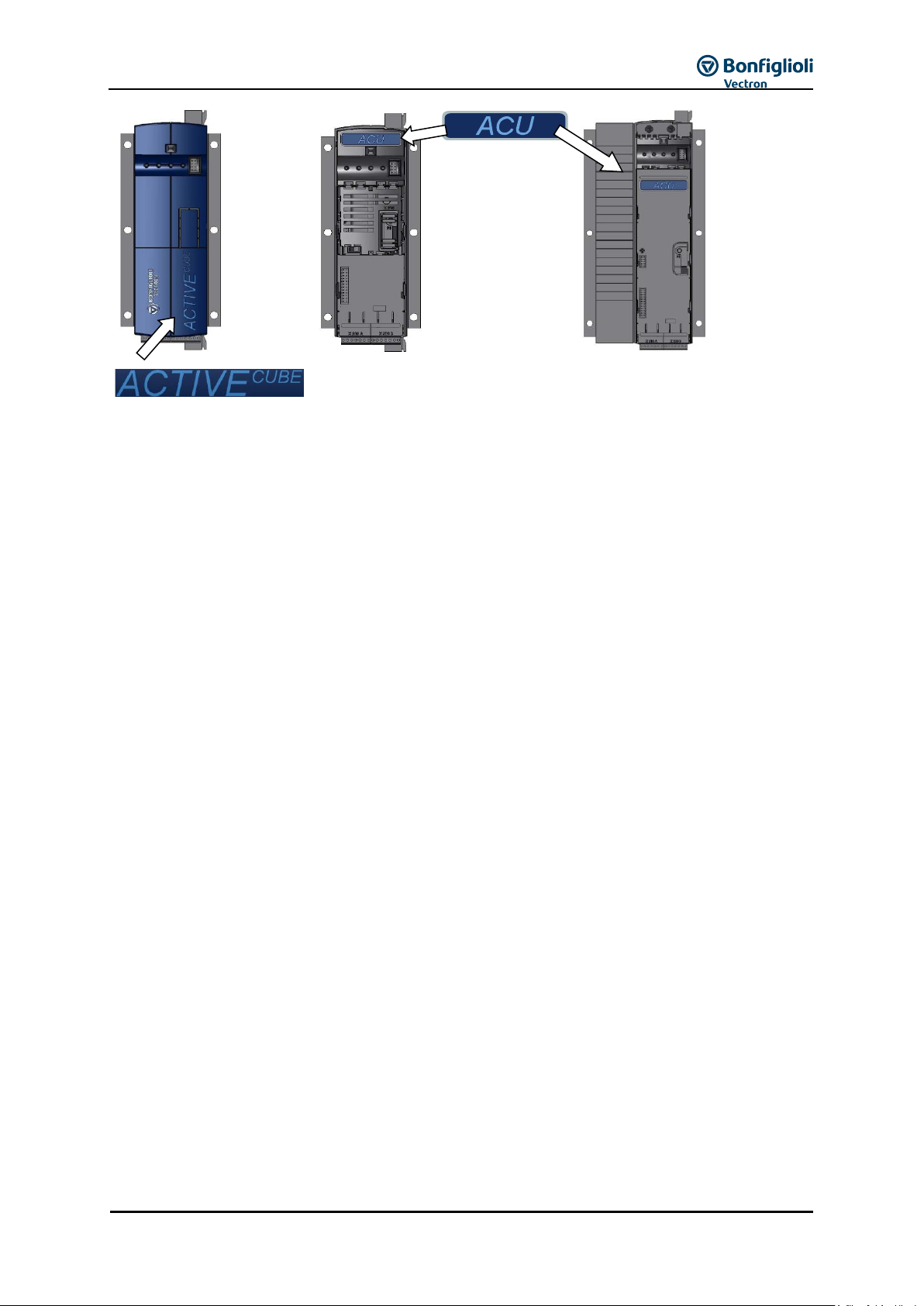
The ACU series can be identified by its label on the case and the identification below the top cover.
12/16
Operating Instructions ACU
13
(Position of ID
depends on size)
Figure 1-1: Device identification
1.3 Warranty and liability
BONFIGLIOLI VECTRON GmbH (hereinafter referred to as “manufacturer”) notes that the contents of
this Operating Instructions document do not form part of any previous or existing agreement,
assurance or legal relationship between the manufacturer and the user of these Operating
Instructions (hereinafter referred to as the “User”). Neither are they intended to supplement or
replace such agreements, assurances or legal relationships. Any obligations of the manufacturer shall
solely be based on the relevant purchase agreement which also includes the complete and solely valid
warranty stipulations. These contractual warranty provisions are neither extended nor limited by the
specifications contained in this documentation.
The manufacturer reserves the right to correct or amend the specifications, product information and
omissions in these operating instructions without prior notice. The manufacturer assumes no
responsibility to update these Operating Instructions. The manufacturer shall not be liable for any
damage, injuries or costs which may be caused by the aforementioned reasons.
In addition, the manufacturer excludes any warranty and disclaims all liability, including without
limitation direct, indirect, special, punitive, incidental, exemplary or consequential damages arising out
of or in connection with one or more of the following causes:
inappropriate use of the frequency inverter,
non-compliance with the instructions, warnings and prohibitions contained in the
documentation,
unauthorized modifications of the solar inverter,
insufficient monitoring of parts of the machine/plant which are subject to wear,
repair work at the machine/plant not carried out properly or in time,
catastrophes by external impact and Force Majeure.
1.4 Obligation
This Operating Instructions document must be read before commissioning. Anybody entrusted with
tasks in connection with the
- transport,
- assembly,
- installation of the frequency inverter and
- operation of the frequency inverter
must have read and understood the Operating Instructions and, in particular, the safety instructions in
order to prevent personal and material losses.

14
Operating Instructions ACU
12/16
1.5 Copyright
Any copyrights relating to this document shall remain with
BONFIGLIOLI VECTRON GmbH
Europark Fichtenhain B6
47807 Krefeld
Germany
This document is intended for the operator of the frequency inverter. Any disclosure or copying of this
document, exploitation and communication of its contents (as hardcopy or electronically) shall be
forbidden, unless permitted expressly.
Any non-compliance will constitute an offense against the copyright law, the law against unfair
competition and the German Civil Code and may result in claims for damages. All rights relating to
patent, utility model or design registration reserved.
1.6 Storage
The documentation forms an integral part of the frequency inverter. It must be stored such that it is
accessible to operating staff at all times. In case the frequency inverter is sold to other users, this
Operating Instructions document must also be handed over.

12/16
Operating Instructions ACU
15
2 General safety instructions and information on use
The chapter "General safety instructions and information on use" contains general safety instructions
for the Operator and the Operating Staff. At the beginning of certain main chapters, some safety
instructions are included which apply to all work described in the relevant chapter. Special workspecific safety instructions are provided before each safety-relevant work step.
2.1 Terminology
According to the documentation, different activities must be performed by certain persons with certain
qualifications.
The groups of persons with the required qualification are defined as follows:
Operator
This is the entrepreneur/company who/which operates the frequency inverter and uses it as per the
specifications or has it operated by qualified and instructed staff.
Operating staff
The term Operating Staff covers persons instructed by the Operator of the frequency inverter and
assigned the task of operating the frequency inverter.
Skilled Personnel
The term Skilled Personnel covers staff that are assigned special tasks by the Operator of the
frequency inverter, e.g. installation, maintenance and service/repair and troubleshooting. Based on
their qualification and/or know-how, Skilled Personnel must be capable of identifying defects and
assessing functions.
Qualified electrician
The term Qualified Electrician covers qualified and trained staff who has special technical know-how
and experience with electrical installations. In addition, Qualified Electricians must be familiar with the
applicable standards and regulations, they must be able to assess the assigned tasks properly and
identify and eliminate potential hazards.
Instructed person
The term Instructed Person covers staff who was instructed and trained about/in the assigned tasks
and the potential hazards that might result from inappropriate behavior. In addition, instructed
persons must have been instructed in the required protection provisions, protective measures, the
applicable directives, accident prevention regulations as well as the operating conditions and verified
their qualification.
Expert
The term Expert covers qualified and trained staff who has special technical know-how and experience
relating to frequency inverter. Experts must be familiar with the applicable government work safety
directives, accident prevention regulations, guidelines and generally accepted rules of technology in
order to assess the operationally safe condition of the frequency inverter.
2.2 Designated use
The product is a frequency inverter. It is designed for
installation in machines and electrical equipment
industrial environments
The frequency inverter is designed according to the state of the art and recognized safety regulations.
The frequency inverters are electrical drive components intended for installation in industrial plants or
machines. Commissioning and start of operation is not allowed until it has been verified that the
machine meets the requirements of the EC Machinery Directive 2006/42/EC and DIN EN 60204-1.
The frequency inverters meet the requirements of the low voltage directive 2006/95/EEC and DIN
EN 61800-5-1. CE-labeling is based on these standards. Responsibility for compliance with the EMC
Directive 2004/108/EC lies with the operator. Frequency inverters are only available at specialized
dealers and are exclusively intended for commercial use as per EN 61000-3-2.
No capacitive loads may be connected to the frequency inverter.

16
Operating Instructions ACU
12/16
The technical data, connection specifications and information on ambient conditions are indicated on
the rating plate and in the documentation and must be complied with in any case.
2.3 Misuse
Any use other than that described in "Designated use" shall not be permissible and shall be
considered as misuse.
For example, the machine/plant must not be operated
- by uninstructed staff,
- while it is not in perfect condition,
- without protection enclosure (e.g. covers),
- without safety equipment or with safety equipment deactivated.
The manufacturer shall not be held liable for any damage resulting from such misuse. The sole risk
shall be borne by the operator.
2.3.1 Explosion protection
The frequency inverter is an IP 20 ingress protection rating device. For this reason, use of the device
in explosive atmospheres is not permitted.
2.4 Residual risks
Residual risks are special hazards involved in handling of the frequency inverter which cannot be
eliminated despite the safety-compliant design of the device. Residual risks are not obviously
identifiable and can be a potential source of injury or a health hazard.
Typical residual hazards include:
Electrical hazard
Danger of contact with energized components due to a defect, opened covers or enclosures or
improper working on electrical equipment.
Danger of contact with energized components in frequency inverter if no external disconnection
device was installed by the operator.
During operation, all covers must be installed correctly, and all electrical cabinet doors must be closed
to minimize electrical hazards.
When LEDs and other indicating elements on the frequency inverter go out, this does not necessarily
mean that the device is deenergized. Before carrying out any work on the device where contact with
energized parts might be possible, check in any case, i.e. irrespective of the status of any indicating
elements that may be installed, if the device is deenergized.
Charged capacitors in DC link
Sizes 1 through 7 (up to 132 kW): The DC-link may have dangerous voltage levels even up to 3
minutes after shutdown.
Electrostatic charging
Touching electronic components entails the risk of electrostatic discharges.
Thermal hazards
Risk of accidents by hot machine/plant surfaces, e.g. heat sink, transformer, fuse or sine filter.
Danger of equipment falling down/over, e.g. during transport
Center of gravity is not the middle of the electrical cabinet modules.
2.5 Safety and warning signs on frequency inverter
Comply with all safety instructions and danger information provided on the frequency inverter.
Safety information and warnings on the frequency inverter must not be removed.
12/16
Operating Instructions ACU
17
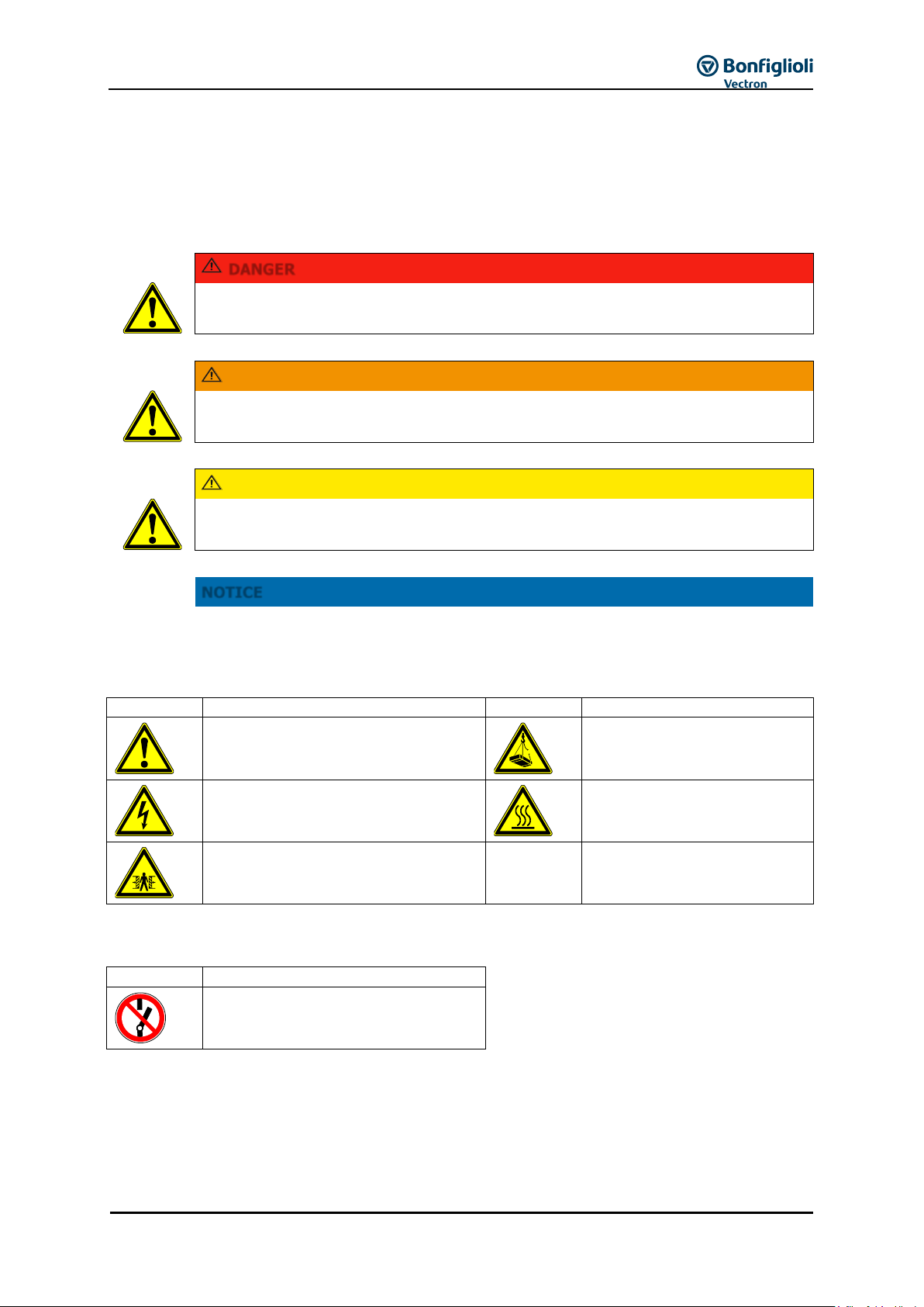
DANGER
Identification of immediate threat holding a high risk of death or serious injury if not
avoided.
WARNING
Identification of immediate threat holding a medium risk of death or serious injury if
not avoided.
CAUTION
Identification of immediate threat holding a low risk of minor or moderate physical
injury if not avoided.
NOTICE
Identification of a threat holding a risk of material damage if not avoided.
Symbol
Meaning
Symbol
Meaning
General hazard
Suspended load
Electrical voltage
Hot surfaces
Danger of crushing
Symbol
Meaning
No switching; it is forbidden to switch
the machine/plant, assembly on
2.6 Warning information and symbols used in the Operating
Instructions
2.6.1 Hazard classes
The following hazard identifications and symbols are used in the Operating Instructions to mark
particularly important information:
2.6.2 Hazard symbols
2.6.3 Prohibition signs
18
Operating Instructions ACU
12/16
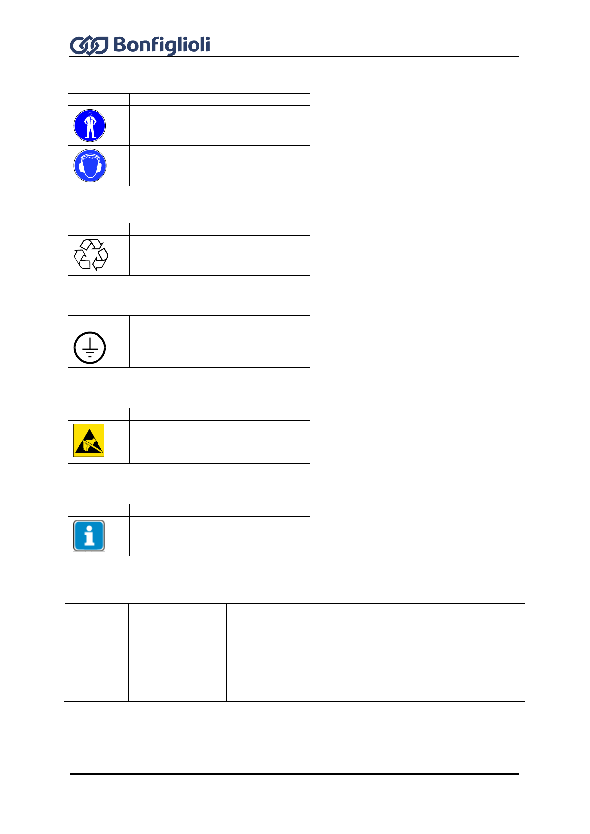
Symbol
Meaning
Wear body protection
Wear ear protectors
Symbol
Meaning
Recycling, to avoid waste, collect all
materials for reuse
Symbol
Meaning
Ground connection
Symbol
Meaning
ESD: Electrostatic Sensitive Devices,
i.e. components and assemblies
sensitive to electrostatic energy
Symbol
Meaning
Tips and information making using the
frequency inverter easier.
Example
Font style
Use
1234
bold
Representation of parameter numbers
Parameter
inclined,
font: Times New
Roman
Representation of parameter names
P.1234
bold
Representation of parameter numbers without name, e.g. in
formulas
Q.1234
bold
Representation of source numbers
2.6.4 Personal safety equipment
2.6.5 Recycling
2.6.6 Grounding symbol
2.6.7 ESD symbol
2.6.8 Information signs
2.6.9 Font style in documentation

12/16
Operating Instructions ACU
19
2.7 Directives and guidelines to be adhered to by the operator
The operator must follow the following directives and regulations:
Ensure that the applicable workplace-related accident prevention regulations as well as other
applicable national regulation are accessible to the staff.
An authorized person must ensure, before using the frequency inverter, that the device is used in
compliance with its designated use and that all safety requirements are met.
Additionally, comply with the applicable laws, regulations and directives of the country in which
the frequency inverter is used.
For liquid cooled frequency inverters, comply with the cooling water guideline VGB-R 455 P.
Any additional guidelines and directives that may be required additionally shall be defined by the
operator of the machine/plant considering the operating environment.
2.8 Operator's general plant documentation
In addition to the Operating Instructions, the operator should issue separate internal user
manuals for the frequency inverter. The Operating Instructions of the frequency inverter must be
included in the Operating Instructions of the whole plant.
2.9 Operator's/operating staff's responsibilities
2.9.1 Selection and qualification of staff
Any work on the frequency inverter may only be carried out by skilled personnel. The staff must
not be under the influence of any drugs. Note the minimum age required by law. Define the staff's
responsibility pertaining to all work on the frequency inverter clearly.
Work on the electrical components may only be performed by a qualified electrician according to
the applicable rules of electrical engineering.
The operating staff must be trained for the relevant work to be performed.
2.9.2 General work safety
In addition to the Operating Instructions of the machine/plant, any applicable legal or other
regulations relating to accident prevention and environmental protection must be complied with.
The staff must be instructed accordingly.
Such regulations and/or requirements may include, for example, handling of hazardous media and
materials or provision/use of personal protective equipment.
In addition to these Operating Instructions, issue any additional directives that may be required to
meet specific operating requirements, including supervision and reporting requirements, e.g.
directives relating to work organization, workflow and employed staff.
Unless approved of expressly by the manufacturer, do not modify the frequency inverter in any
way, including addition of attachments or retrofits.
Only use the frequency inverter if the rated connection and setup values specified by the
manufacturer are met.
Provide appropriate tools as may be required for performing all work on the frequency inverter
properly.
2.9.3 Ear protectors
The frequency inverter produces noise. Due to noise development, frequency inverters should
only be installed in normally unstaffed areas.
Noise emission in operation is < 85 dB(A) in the case of sizes 1 through 7.

20
Operating Instructions ACU
12/16
2.10 Organizational measures
2.10.1 General
Train your staff in the handling and use of the frequency inverter and the machine/plant as well
as the risks involved.
Use of any individual parts or components of the frequency inverter in other parts of the
operator's machine/plant is prohibited.
Optional components for the frequency inverter must be used in accordance with their designated
use and in compliance with the relevant documentation.
2.10.2 Use in combination with third-party products
Please note that Bonfiglioli Vectron MDS GmbH will not accept any responsibility for compatibility
with third-party products (e.g. motors, cables or filters)..
In order to enable optimum system compatibility Bonfiglioli Vectron MDS GmbH offers
components facilitating commissioning and providing optimum synchronization of the
machine/plant parts in operation.
If you use the frequency inverter in combination with third-party products, you do so at your own
risk.
2.10.3 Handling and installation
Do not commission any damaged or destroyed components.
Prevent any mechanical overloading of the frequency inverter. Do not bend any components and
never change the isolation distances.
Do not touch any electronic construction elements and contacts. The frequency inverter is
equipped with components which are sensitive to electrostatic energy and can be damaged if
handled improperly. Any use of damaged or destroyed components will endanger the
machine/plant safety and shall be considered as non-compliance with the applicable standards.
Only install the frequency inverter in a suitable operating environment. The frequency inverter is
exclusively designed for installation in industrial environments.
If seals are removed from the case, this can result in the warranty becoming null and void.
2.10.4 Electrical connections
The five safety rules must be complied with.
Never touch live terminals. In sizes 1 through 7, the DC-link may have dangerous voltage levels
up to 3 minutes after shutdown.
When performing any work on/with the frequency inverter, always comply with the applicable
national and international regulations/laws on work on electrical equipment/plants of the country
in which the frequency inverter is used.
The cables connected to the frequency inverters may not be subjected to high-voltage insulation
tests unless appropriate circuitry measures are taken before.
Only connect the frequency inverter to suitable supply mains. The frequency inverter may be
operated in TN, TT and IT grid types. Precautions must be taken for operation in IT grids, see
Chapter 7 "Electrical installation". Operation in a corner-grounded TN grid shall not be permissible.
2.10.4.1 The five safety rules
When working on/in electrical plants, always follow the five safety rules:
1 Isolate
2 Secure to prevent restarting
3 Check isolation
4 Earth and short-circuit
5 Cover or shield neighboring live parts

12/16
Operating Instructions ACU
21
2.10.5 Safe operation
During operation of the frequency inverter, always comply with the applicable national and
international regulations/laws on work on electrical equipment/plants.
Before commissioning and the start of the operation, make sure to fix all covers and check the
terminals. Check the additional monitoring and protective devices according to the applicable
national and international safety directives.
During operation, all covers must be installed correctly, and all electrical cabinet doors must be
closed. During operation, never open the machine/plant.
No connection work shall be carried out while power supply is on.
The machine/plant holds high voltage levels during operation, is equipped with rotating parts
(fan) and has hot surfaces. Any unauthorized removal of covers, improper use, wrong installation
or operation may result in serious injuries or material damage.
Some components, e.g. the heat sink or braking resistor, may be hot even some time after the
machine/plant was shut down. Don't touch any surfaces directly after shutdown. Wear safety
gloves where necessary.
The frequency inverter may hold dangerous voltage levels until the capacitor in the DC link is
discharged. After shutdown, wait for at least 3 minutes (sizes 1 through 7) before starting any
electrical or mechanical work on the frequency inverter. Even after this waiting time, make sure
that the equipment is deenergized in accordance with the safety rules before starting the work.
In order to avoid accidents or damage, only skilled personnel and electricians may carry out the
work such as installation, commissioning or setup.
In the case of a defect of terminals and/or cables, immediately disconnect the frequency inverter
from mains supply.
Persons not familiar with the operation of the frequency inverter and children must not have
access to the device.
Do not bypass nor decommission any protective devices.
The frequency inverter may be connected to power supply every 60 s. This must be considered
when operating a mains contactor in jog operation mode. For commissioning or after an
emergency stop, a non-recurrent, direct restart is permissible.
After a failure and restoration of the power supply, the motor may start unexpectedly if the
AutoStart function is activated.
If staff are endangered, a restart of the motor must be prevented by means of external circuitry.
Before commissioning and the start of the operation, make sure to fix all covers and check the
terminals. Check the additional monitoring and protective devices according to EN 60204 and
applicable the safety directives (e.g. Working Machines Act or Accident Prevention Directives).

22
Operating Instructions ACU
12/16
Electric scrap, electronic components, lubricants and other utility materials must be
treated as special waste and may only be disposed of by specialized companies.
In any case, comply with any applicable national disposal regulations as regards
environmentally compatible disposal of the frequency inverter. For more details,
contact the competent local authorities.
2.10.6 Maintenance and service/troubleshooting
Visually inspect the frequency inverter when carrying out the required maintenance work and
inspections at the machine/plant.
Perform the maintenance work and inspections prescribed for the machine carefully, including the
specifications on parts/equipment replacement.
Work on the electrical components may only be performed by a qualified electrician according to
the applicable rules of electrical engineering. Only use original spare parts.
Unauthorized opening and improper interventions in the machine/plant can lead to personal injury
or material damage. Any repair work may only be carried out by the manufacturer or persons
approved/licensed by the manufacturer. Any repair work must be carried out by qualified
electricians. Check protective equipment regularly.
Before performing any maintenance work, the machine/plant must be disconnected from mains
supply and secured against restarting. The five safety rules must be complied with.
2.10.7 Final decommissioning
Unless separate return or disposal agreements were made, recycle the disassembled frequency
inverter components:
Scrap metal materials
Recycle plastic elements
Sort and dispose of other component materials

12/16
Operating Instructions ACU
23
WARNING
Improper installation of the safety circuitry may result in uncontrolled starting of the
drive. This may cause death, serious injuries and significant material damage.
Safety functions may only be installed and commissioned by skilled personnel.
The STO function is not suitable for emergency stop as per EN 60204. An emergency
stop can be realized by installing a mains contactor.
An emergency stop according to EN 60204 must be functioning in all operation modes
of the frequency inverter. Resetting of an emergency stop must not result in
uncontrolled starting of the drive.
The drive is started again when the function STO is no longer required. In order to
comply with EN 60204, ensure by taking external measures that the drive does not
start without prior confirmation.
Without a mechanical brake, the drive will not stop immediately but coast to a
standstill. If this may result in personal or material damage, additional safety
measures must be taken.
If persons may be endangered after disconnection of the motor power supply by
STO, access to the hazard areas must be prevented until the drive has stopped.
Check the safety function at regular intervals according to the results of your risk
analysis. Bonfiglioli Vectron MDS GmbH recommends that the check be performed
after one year, at the latest.
The STO function is fail-safe. However, on rare occasions, the occurrence of
component defects may cause jerking of the motor shaft (max. 180°/pole pair, e. g.
jerk by 90° with 4-pole motor, 180°/2). Check if this causes a dangerous movement
of the machine.
If the STO function is used, the special safety, installation and instructions on use
instructions shall be complied with.
The application manual "Safe Torque Off STO" must be complied with, particularly if
the safety function described there is used.
Warning! Dangerous voltage!
The safety function “Safe Torque Off” may only be used if mechanical work is to be
performed on the driven machines, not for work on live components.
After disconnection of an external DC 24 V power supply, the DC link of the frequency
inverter is still connected to mains supply.
Even if power supply to the motor is disconnected, and the motor is coasting to a
standstill or has already stopped, high voltages may still be present on the motor
terminals.
Before working (e. g. maintenance) on live parts, the plant must always be
disconnected from mains supply (main switch). This must be documented on the
plant.
When the function “Safe Torque Off” is triggered, the motor is not isolated from the
DC link of the frequency inverter. High voltage levels may be present at the motor.
Do not touch live terminals.
2.11 Safety Instructions on Function “Safe Torque Off” (STO)
The function „Safe Torque Off“ (STO) is a functional safety feature, i.e. it protects staff from damage,
provided that projecting, installation and operation are performed properly. This function does not
disconnect the plant from power supply.
In order to disconnect the plant from power supply (e.g. for maintenance work), an "Emergency Stop"
provision as per EN 60204 must be installed.

24
Operating Instructions ACU
12/16
NOTICE
Draining the heat sink
Liquid cooled devices may be transported only with the heat sink completely
drained of the coolant. Use compressed air to drain the heat sink radiator.
NOTICE
Damage caused by incorrect storage
Wrong or inappropriate storage may result in damage, e.g. due to moisture and
dirt. Avoid major temperature variations and high air humidity.
During storage, protect the device against moisture and dirt.
WARNING
High weight and unusual center of gravity!
Tilting the frequency inverter may result in death or serious injuries. Due to the size and
weight of the frequency inverter, there is the risk of accidents during transport. Center
of gravity is not the middle of the frequency inverter. The underside of the frequency
inverter, due to its design, cannot support the frequency inverter.
Take utmost care during transport in order to prevent damage and deformation.
Transport, attachment and lifting of loads may only be carried out by specially
instructed staff who are familiar with the work.
Only use suitable transport and lifting equipment with sufficient carrying capacity.
The lifting cables/chains used must be able to carry the weight of the frequency
inverter. Check the ropes or chains for damage.
Wear appropriate safety clothing.
When lifting the frequency inverter up ensure that it does not fall over, is displaced,
swings out or falls down.
Before the frequency inverter is lifted up, everybody must have left the work area.
Before transport, make sure the transport path has sufficient carrying capacity.
Do not step under suspended loads.
Do not put the frequency inverter down in upright position without providing a
suitable supporting structure.
3 Storage and transport
3.1 Storage
The frequency inverters must be stored in an appropriate way. During storage, the devices must
remain in their original packaging.
The units may only be stored in dry rooms which are protected against dust and moisture and are
exposed to small temperature deviations only. The requirements of DIN EN 60721-3-1 for storage,
DIN EN 60721-3-2 for transport and labeling on the packaging must be met.
The duration of storage without connection to the permissible nominal voltage may not exceed
one year. After one year of storage, connect the device to mains voltage for 60 minutes.
3.2 Special safety instructions on transport of heavy frequency inverters

12/16
Operating Instructions ACU
25
For information on the weight and dimensions of the frequency inverter, refer to chapter 5
“Technical data”.
Ensure that all packaging materials are disposed of in an environmentally compatible
manner.
3.3 Dimensions/weight
3.4 Transfer to place of installation
Transfer to the place of installation is done with the product in its original packaging. Frequency
inverters as from size 7 must be transferred to the place of installation in horizontal position, rear-side
down. A fork lift truck or crane with crane fork can be used for transfer to the place of installation.
Apply the fork in the middle of the transport unit.
Secure the transport unit to prevent it from falling down and overturning.
Lift the transport unit up carefully.
At the place of installation, put the transport unit down on a level and bearing surface.
3.5 Unpacking the device
Carefully remove packaging.
Check if the delivered devices corresponds to the order.
Check the device for transport damage and completeness.
Any defects/damage must be reported to the supplier immediately.
3.6 Bringing the device into installation position
3.6.1 Sizes 1 through 6
Depending on the weight, one or two persons are required for lifting the device into the
installation position in the electrical cabinet. Installation, see Chapter 6 "Mechanical installation".
3.6.2 Sizes 7 and 8
Fix two crane eyes (M8) in the marked threaded holes on the top side of the device.
Use appropriate lifting means.

26
Operating Instructions ACU
12/16
NOTICE
The pull angle must not be smaller than 60°.
NOTICE
Do not leave the device standing in upright position.
Use appropriate lifting means and a crane to lift the frequency inverter up carefully. Bring the
device into vertical position by turning it up on the pallet via the rear lower edge of the case.
Move the frequency inverter to its installation position in the electrical cabinet and fix it there, see
Chapter 6 "Mechanical installation".
After mechanical installation, disconnect the device from the crane and remove the crane eyes.

12/16
Operating Instructions ACU
27
Scope of supply
Scope of supply
A
Frequency inverter
B
Terminal strip X1 (Phoenix ZEC 1,5/ST7,5)
Plug-in terminals for mains connection and DC linking
C
Terminal strip X10 (Phoenix ZEC 1.5/3ST5.0)
Plug-in terminals for the relay output
D
Standard fixtures for vertical assembly
E
Quick Start Guide and Operating Instructions
F
Terminal strip X2 (Phoenix ZEC 1,5/ST7,5)
Plug-in terminal for braking resistor and motor connection
G
Control terminals X210A / X210B (Wieland DST85 / RM3.5)
Plug-in terminal for connection of the control signals
Please check incoming goods for quality, quantity and nature without delay. Obvious
defects such as exterior damage of the packing and/or the unit must be notified to the
sender within seven days for insurance reasons.
4 Scope of supply
Due to modular hardware components, the frequency inverters can be integrated in the automation
concept easily. The scope of delivery described can be supplemented by optional components and
adapted to the customer-specific requirements. The plug-in type connection terminals enable a safe
function and quick and easy assembly.
4.1 Sizes 1 and 2: ACU 201 (up to 3.0 kW) and 401 (up to 4.0 kW)
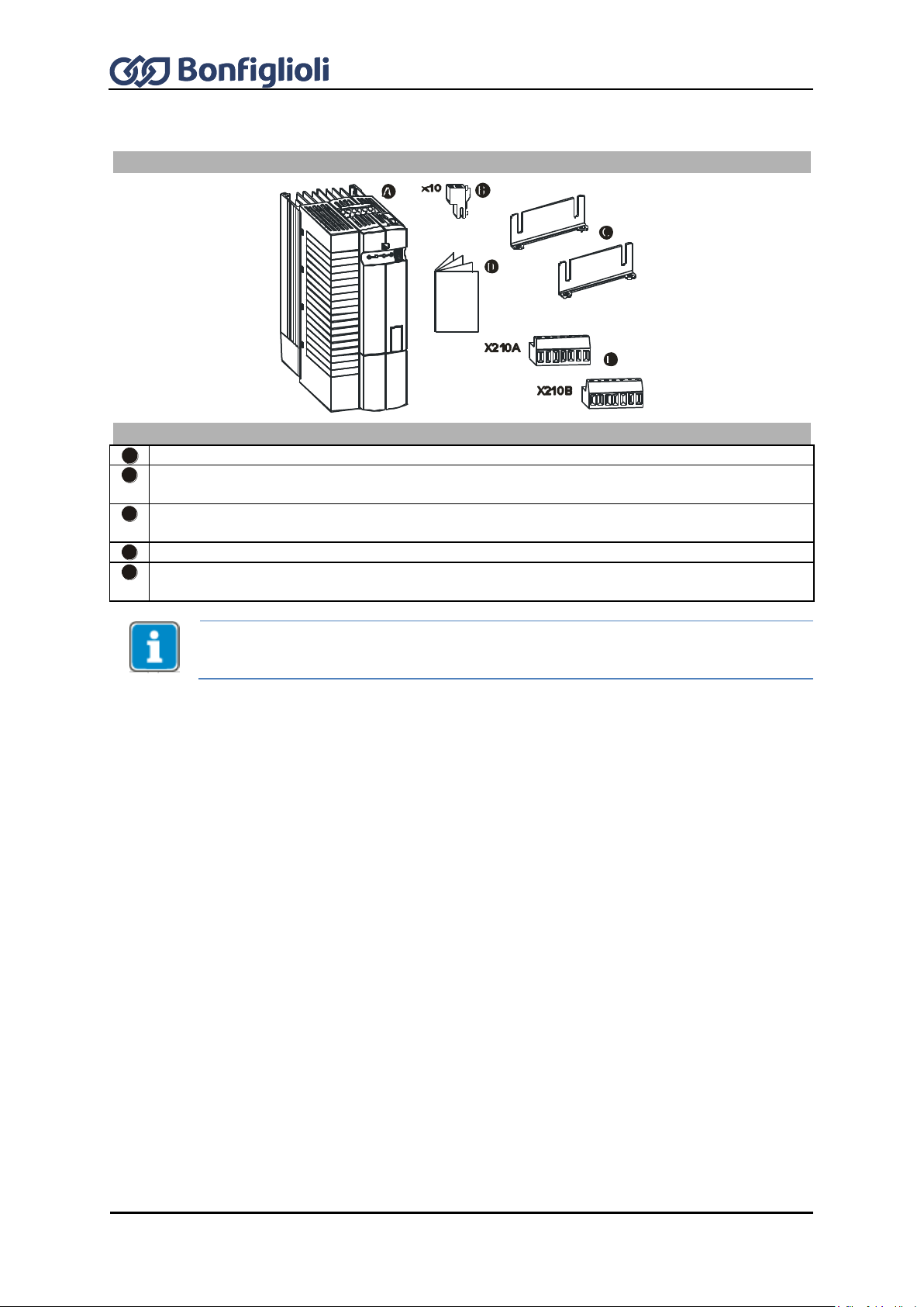
28
Operating Instructions ACU
12/16
Scope of supply
Scope of supply
A
Frequency inverter
B
Terminal strip X10 (Phoenix ZEC 1.5/3ST5.0)
Plug-in terminals for the relay output
C
Standard fittings with fitting screws (M4x20, M4x60)
for vertical assembly
D
Quick Start Guide and Operating Instructions
E
Control terminals X210A / X210B (Wieland DST85 / RM3.5)
Plug-in terminal for connection of the control signals
Please check incoming goods for quality, quantity and nature without delay. Obvious
defects such as exterior damage of the packing and/or the unit must be notified to the
sender within seven days for insurance reasons.
4.2 Sizes 3 and 4: ACU 201 (4.0 to 9.2 kW) and 401 (5.5 to 15.0 kW)

12/16
Operating Instructions ACU
29
Scope of supply
Scope of supply
A
Frequency inverter
B
Terminal strip X10 (Phoenix ZEC 1.5/3ST5.0)
Plug-in terminals for the relay output
C
Standard fittings with fitting screws (M4x20, M4x70)
for vertical assembly
D
Quick Start Guide and Operating Instructions
E
Control terminals X210A / X210B (Wieland DST85 / RM3.5)
Plug-in terminal for connection of the control signals
Please check incoming goods for quality, quantity and nature without delay. Obvious
defects such as exterior damage of the packing and/or the unit must be notified to the
sender within seven days for insurance reasons.
4.3 Size 5 ACU 401 (18.5 to 30.0 kW)

30
Operating Instructions ACU
12/16
Scope of supply
Scope of supply
A
Frequency inverter
The illustration shows an air-cooled frequency inverter as an example.
B
Terminal strip X10 (Phoenix ZEC 1.5/3ST5.0)
Plug-in terminals for the relay output
C
For air-cooled frequency inverters only: Standard fittings with fitting screws (M5x20) for
vertical assembly
D
Quick Start Guide and Operating Instructions
E
Control terminals X210A / X210B (Wieland DST85 / RM3.5)
Plug-in terminal for connection of the control signals
Please check incoming goods for quality, quantity and nature without delay. Obvious
defects such as exterior damage of the packing and/or the unit must be notified to the
sender within seven days for insurance reasons.
4.4 Size 6 ACU 401 (37.0 to 65.0 kW)

12/16
Operating Instructions ACU
31
Scope of supply
Scope of supply
A
Frequency inverter
The illustration shows an air-cooled frequency inverter as an example.
B
Terminal strip X10 (Phoenix ZEC 1.5/3ST5.0)
Plug-in terminals for the relay output
C
Control terminals X210A / X210B (Wieland DST85 / RM3.5)
Plug-in terminal for connection of the control signals
D
Quick Start Guide and Operating Instructions
Please check incoming goods for quality, quantity and nature without delay. Obvious
defects such as exterior damage of the packing and/or the unit must be notified to the
sender within seven days for insurance reasons.
4.5 Size 7 ACU 401 (75.0 to 132.0 kW)

32
Operating Instructions ACU
12/16
CE conformity
The ACU frequency inverters meet the requirements of the low voltage
directive 2006/95/EEC and DIN EN 61800-5-1.
EMC directive
For proper installation of the frequency inverter in order to meet the
requirements of EN 61800-3, please comply with the installation instructions in
these operating instructions.
Interference
immunity
The ACU frequency inverters meet the requirements of EN 61800-3 for use in
industrial environments.
UL Approval
The frequency inverters are also marked with the UL label according to UL508c,
which proves that they also meet the requirements of the CSA Standard C22.2No. 14.
ACU 401 device series are UL-approved in sizes 1 through 7, ACU 201 devices
are UL-approved in sizes 1 and 2.
Safety function
The function is described in application manual "Safe Torque Off STO".
Ambient
temperature
Storage: -25 ... 55°C (for liquid cooling: drain the heat sink completely!)
Transport: -25 ... 70°C (for liquid cooling: drain the heat sink completely!)
Operation: 0…55°C; as from 40 °C power reduction should be considered.
Ambient pressure
70 ... 106 kPa (to be checked)
Environmental
class
Operation: 3K3 (EN60721-3-3)
Relative humidity
Air cooling: 15…85%, no water condensation
Liquid cooling: 15…95%, non-condensing
For liquid cooling: Comply with the notes on “Heat sink condensation
protection” in the “Operating Instructions Liquid Cooling Supplemental”.
In addition, the following environmental conditions must be considered for
operation according to DIN EN 60721-3-3:
3Z1 (negligible thermal radiation)
3B1 (no biological impact)
3C1 (chemically active substances, limits as per standard)
3S1 (mechanically active substances, no sand in air, limits as per standard)
3M4 (mechanical vibration and shocks, limits as per standard)
Ingress protection
rating
IP20 if covers and connection terminals are used properly.
Altitude of
installation
Up to 1000 m at rated specifications.
Up to 4000 m at reduced power.
Storage
Storage according to EN 50178.
After one year of storage, connect the device to mains voltage for 60 minutes.
Permitted
grid types
The frequency inverter may be operated in TN, TT and IT grid types.
Precautions must be taken for operation in IT grids, see Chapter 7 "Electrical
installation". Operation in a corner-grounded TN grid shall not be permissible.
Overload
capacity
Continuous operation 100 % IN
Up to 150% IN for 60 s
Up to 200% IN for 1 s
Devices -01, 03
(0.25 & 0.37
kW):
Up to 200% IN for
60 s
Up to 200% IN for
1 s
Overload capacity can be used every 10 minutes. For the individual overload
capacity, refer to the technical data.
5 Technical data
5.1 General technical data

12/16
Operating Instructions ACU
33
Max. permissible
short-circuit
current to be
expected with
mains supply
Up to 132 kW device power (size 7): 5 kA
Contamination
level
The frequency inverters are designed for Pollution Degree 2.
Overvoltage
category
The frequency inverters are designed for Overvoltage Category III.
Functions
Control methods adjusted to motors and application (configuration).
Adjustable speed/torque control.
Various protection functions for motor and frequency inverter.
Positioning absolute or relative to a reference point.
Catching function.
Special brake control and load detection for lifting gear.
S-ramps for jerk limitation during acceleration and deceleration.
Technology (PI) controller.
Parameterizable Master-Slave operation via system bus.
Error memory.
Simplified and extended control via PC (commissioning,
parameterization, data set backup, diagnosis with Scope).
Parameterization
Freely programmable digital inputs and outputs.
Various logic modules for linking and processing of signals.
Four separate data sets incl. motor parameters.
Control terminal X210A
Control terminal X210B
X210A.1
DC 20 V output (I
max
=180 mA)
or DC 24 V ±10% input for
external power supply
X210B.1
Digital input 1)
X210A.2
GND 20 V/ GND 24 V (ext.)
X210B.2
Digital input STOB
(second shut-down path)
safety
relevant
X210A.3
Digital input STOA
(first shut-down path)
safety
relevant
X210B.3
Digital output 1)
X210A.4
Digital inputs
1)
X210B.4
Multifunction output 1) (voltage
signal, proportional act. frequency,
factory settings)
X210A.5
X210B.5
Supply voltage DC 10 V for
reference value potentiometer,
(I
max
=4 mA)
X210A.6
X210B.6
Multifunction input 1) (reference
speed 0 … +10 V, factory settings)
X210A.7
X210B.7
Ground 10 V
Relay output X10
X10
Inverter error message 1)
1)
Control terminals are freely configurable.
Control “Safe Torque Off”: Contacts on X210A.3 and X210B.2 open.
Release of frequency inverter: Contacts on X210A.3 and X210B.2 closed.
5.2 Technical Data – Control Electronic Equipment

34
Operating Instructions ACU
12/16
By default, the different configurations occupy the control terminals with certain
settings. These settings can be adjusted to the specific application, and various
functions can be assigned freely to the control terminals. For an overview of the
settings, see Page 282 of these Operating Instructions.
Technical data of control terminals
Digital inputs (X210A.3…X210B.2):
Low Signal: DC 0…3 V, High Signal: DC 12…30 V,
Input resistance: 2.3 kΩ, response time: 2 ms (STOA and STOB: 10 ms), PLC compatible,
X210A.6 and X210A.7 additionally: Frequency signal: DC 0 V...30 V, 10 mA at DC 24 V,
f
max
=150kHz
Digital output (X210B.3):
Low Signal: DC 0…3 V, High Signal: DC 12…30 V,
Maximum output current: 50 mA, PLC compatible
Relay output (X10):
Change-over contact, response time approx. 40 ms,
Make contact AC 5 A / 240 V, DC 5 A (ohmic) / 24 V
Break contact AC 3 A / 240 V, DC 1 A (ohmic) / 24 V
Multifunction output (X210B.4):
Analog signal: DC 19…28 V, maximum output current: 50 mA, pulse-width modulated (f
PWM
=
116 Hz),
Digital signal: Low Signal: DC 0…3 V, High Signal: DC 12…30 V, output current: 50 mA,
PLC compatible,
Frequency signal: Output voltage: DC 0…24 V, maximum output current: 40 mA,
maximum output frequency: 150 kHz
Multifunction input (X210B.6):
Analog signal: Input voltage: DC 0… 10 V (R
i
=70 kΩ), input current: DC 0…20 mA (Ri=500
Ω),
Digital signal: Low Signal: DC 0…3 V, High Signal: DC 12 V…30 V, response time: 4 ms, PLC
compatible
Conductor cross-section:
The signal terminals are suitable for the following cable sizes:
with ferrule: 0.25…1.0 mm²
without ferrule: 0.14…1.5 mm²
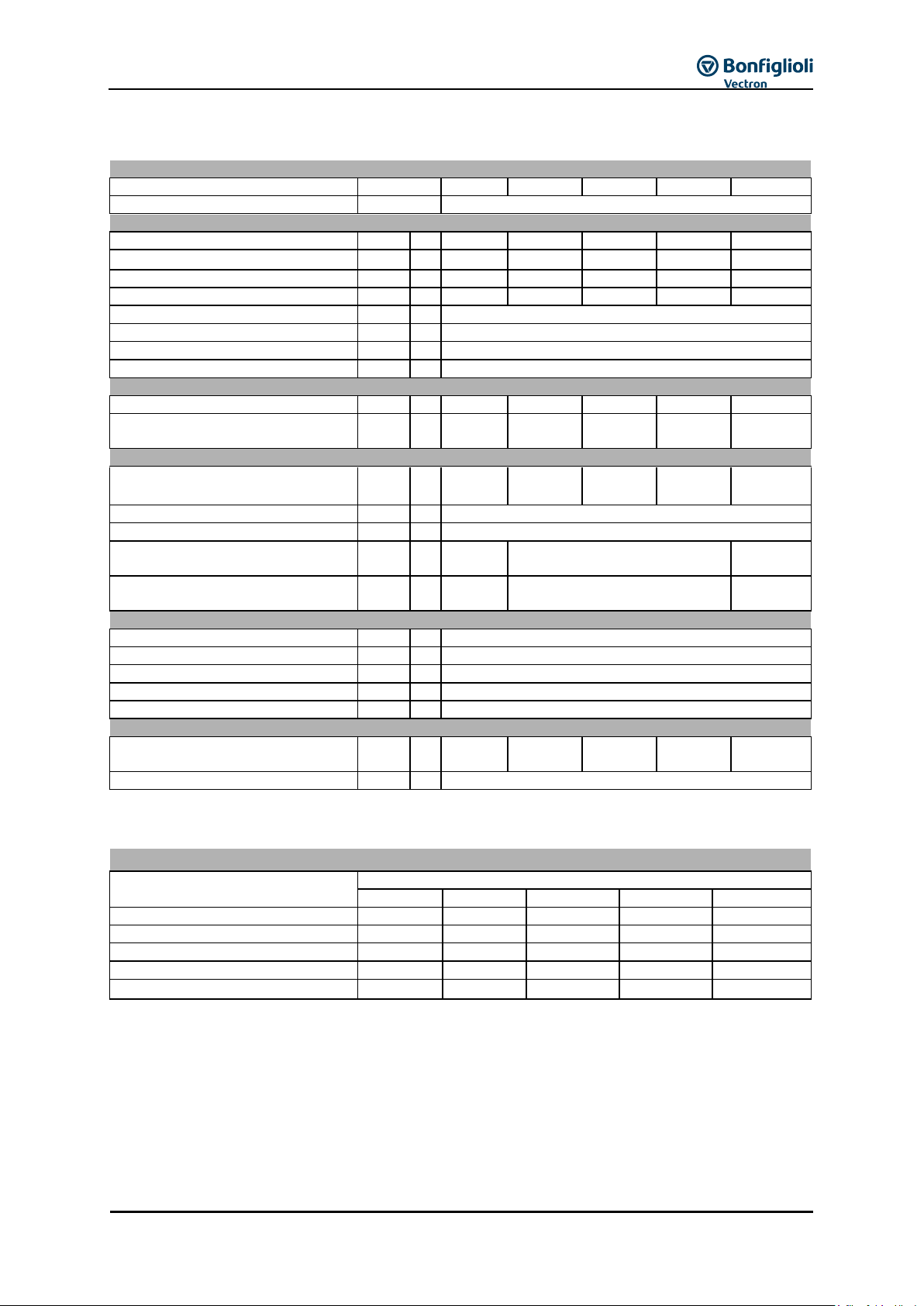
12/16
Operating Instructions ACU
35
Type
ACU 201
-01
-03
-05
-07
-09
Size
1
Output, motor side
Recommended motor shaft power
P
kW
0.25
0.37
0.55
0.75
1.1
Output current
I A 1.6
2.5
3.0
4.0
5,4 5)
Long-term overload current (60 s)
I A 3.2
5.0
4.5
6.0
7.3
Short-time overload current (1 s)
I A 3.2
5.0
6.0
8.0
8.0
Output voltage
U
V
Maximum input voltage, three-phase
Protection
-
-
Short circuit / earth fault proof
Rotary field frequency
f
Hz
0 ... 599, depending on switching frequency
Switching frequency
f
kHz
2, 4, 8, 12, 16
Output, braking resistor
Min. braking resistance
R Ω 100
100
100
100
100
Recommended braking resistor
(U
dBC
= 385 V)
R Ω 430
300
230
160
115
Input, mains side
Mains current3) 3ph
1ph/N/PE; 2ph
I
A
1,6
2.9
2,5
4.5 3 5.4 4 7.2
5.5
1)
9.5 2)
Mains voltage
U
V
184 ... 264
Mains frequency
f
Hz
45 ... 66
Fuse 3ph
1ph/N; 2ph
I
A
6
6
6
10
10
16
UL type 250 VAC RK5, 3ph
1ph/N; 2ph
I
A
6
6
6
10
10
15
Mechanical
Dimensions
HxWxD
mm
190 x 60 x 175
Weight approx.
m
kg
1.2
Ingress protection rating
-
-
IP20 (EN60529)
Connection terminals
A
mm
2
0.2 ... 1.5
Form of assembly
-
-
vertical
Ambient conditions
Energy dissipation (2 kHz switching
frequency)
P W 32
38
43
53
73
Coolant temperature
Tn
°C
0 ... 40 (3K3 DIN IEC 721-3-3)
If required by the customer, the switching frequency may be increased if the output current is reduced at the
same time. Comply with the applicable standards and regulations for this operating point.
Output current 6)
Frequency inverter nominal power
Switching frequency
2 kHz
4 kHz
8 kHz
12 kHz
16 kHz
0.25 kW
1.6 A
1.6 A
1.6 A
1.3 A
1.1 A
0.37 kW
2.5 A
2.5 A
2.5 A
2.1 A
1.7 A
0.55 kW
3.0 A
3.0 A
3.0 A
2.5 A
2.0 A
0.75 kW
4.0 A
4.0 A
4.0 A
3.4 A
2.7 A
1.1 kW
5.4 A 2)
5.4 A
2) 5)
5.4 A
2) 5)
4.5 A
2) 5)
3.7 A 5)
5.3 ACU 201 Size 1 (0.25 to 1.1 kw, 230 V)
1)
Three-phase connection requires a commutating choke.
2)
One- and two-phase connection requires a commutating choke.
3)
Mains current with relative mains impedance ≥ 1% (see Chapter 7 "Electrical installation")
4)
Maximum output current = 9.5 A with single-phase and two-phase connection
5)
Reduction of switching frequency in thermal limit range
6)
Maximum current in continuous operation

36
Operating Instructions ACU
12/16
Type
ACU 201 -11
-13
-15
Size
2
Output, motor side
Recommended motor shaft power
P
kW
1.5
2.2
3,0 4)
Output current
I A 7.0
9.5
12.5
4) 5)
Long-term overload current (60 s)
I A 10.5
14.3
16.2
Short-time overload current (1 s)
I A 14.0
19.0
19.0
Output voltage
U
V
Maximum input voltage, three-phase
Protection
-
-
Short circuit / earth fault proof
Rotary field frequency
f
Hz
0 ... 599, depending on switching frequency
Switching frequency
f
kHz
2, 4, 8, 12, 16
Output, braking resistor
Min. braking resistance
R Ω 37
37
37
Recommended braking resistor
(U
dBC
= 385 V)
R Ω 75
55
37
Input, mains side
Mains current3) 3ph
1ph/N; 2ph
I
A
7
13.2
9.5
16.5 2)
10.5
1)
16.5
2) 4)
Mains voltage
U
V
184 ... 264
Mains frequency
f
Hz
45 ... 66
Fuse 3ph
1ph/N; 2ph
I
A
10
16
16
20
16
20
UL type 250 VAC RK5, 3ph
1ph/N; 2ph
I
A
10
15
15
20
15
20
Mechanical
Dimensions
HxWxD
mm
250 x 60 x 175
Weight approx.
m
kg
1.6
Ingress protection rating
-
-
IP20 (EN60529)
Connection terminals
A
mm
2
0.2 ... 1.5
Form of assembly
-
-
vertical
Ambient conditions
Energy dissipation (2 kHz switching
frequency)
P W 84
115
170
Coolant temperature
Tn
°C
0 ... 40 (3K3 DIN IEC 721-3-3)
If required by the customer, the switching frequency may be increased if the output current is reduced at the
same time. Comply with the applicable standards and regulations for this operating point.
Output current
6)
Frequency inverter nominal power
Switching frequency
2 kHz
4 kHz
8 kHz
12 kHz
16 kHz
1.5 kW
7.0 A
7.0 A
7.0 A
5.9 A
4.8 A
2.2 kW
9.5 A
2)
9.5 A
2)
9.5 A
2)
8.0 A
2)
6.5 A
3.0 kW
2) 4)
12.5 A
1)
12.5 A
1) 5)
12.5 A
1) 5)
10.5 A
1) 5)
8.5 A
5)
5.4 ACU 201 Size 2 (1.5 to 3.0 kW, 230 V)
1)
Three-phase connection requires a commutating choke.
2)
One- and two-phase connection requires a commutating choke.
3)
Mains current with relative mains impedance ≥ 1% (see Chapter 7 "Electrical installation")
4)
Maximum output current = 9.5 A with single-phase and two-phase connection
5)
Reduction of switching frequency in thermal limit range
6)
Maximum current in continuous operation

12/16
Operating Instructions ACU
37
Type
ACU 201 -18
-19
-21
-22
Size
3
4
Output, motor side
Recommended motor shaft power
P
kW
4.0
5.5 4)
7.5
4)
9.2
4)
Output current
I A 18.0
22.0
32.0
35.0
Long-term overload current (60 s)
I A 26.3
30.3
44.5
51.5
Short-time overload current (1 s)
I A 33.0
33.0
64.0
64.0
Output voltage
U
V
Maximum input voltage, three-phase
Protection
-
-
Short circuit / earth fault proof
Rotary field frequency
f
Hz
0 ... 599, depending on switching frequency
Switching frequency
f
kHz
2, 4, 8, 12, 16
Output, braking resistor
Min. braking resistance
R Ω 24
24
12
12
Recommended braking resistor
(U
dBC
= 385 V)
R Ω 30
24
16
12
Input, mains side
Mains current3) 3ph
1ph/N; 2ph
I
A
18
28
2) 7)
20
1)
- 4)
28.2
1)
- 4)
35.6
1)
- 4)
Mains voltage
U
V
184 ... 264
Mains frequency
f
Hz
45 ... 66
Fuse 3ph
1ph/N; 2ph
I
A
25
35
25
- 4)
35
- 4)
50
- 4)
Mechanical
Dimensions
HxWx
D
mm
250 x 100 x 200
250 x 125 x 200
Weight approx.
m
kg
3.0
3.7
Ingress protection rating
-
-
IP20 (EN60529)
Connection terminals
A
mm2
0.2 … 6
0.2 … 16
Form of assembly
-
-
vertical
Ambient conditions
Energy dissipation (2 kHz switching
frequency)
P W 200
225
310
420
Coolant temperature
Tn
°C
0 ... 40 (3K3 DIN IEC 721-3-3)
If required by the customer, the switching frequency may be increased if the output current is reduced at the
same time. Comply with the applicable standards and regulations for this operating point.
Output current 6)
Frequency inverter nominal power
Switching frequency
2 kHz
4 kHz
8 kHz
12 kHz
16 kHz
4.0 kW
18.0 A 2)
18.0 A 2)
18.0 A 2)
15.1 A 2)
12.2 A
5.5 kW 4)
23.0 A 1)
22.7 A
1), 5)
22.0 A
1), 5)
18.5 A 5)
15.0 A 5)
7.5 kW 4)
32.0 A 1)
32.0 A 1)
32.0 A 1)
26.9 A 1)
21.8 A
9.2 kW 4)
40.0 A 1)
38.3 A
1), 5)
35.0 A
1), 5)
29.4 A
1), 5)
23.8 A 5)
5.5 ACU 201 sizes 3 and 4 (4.0 to 9.2 kW, 230 V)
1)
Three-phase connection requires a commutating choke.
2)
One- and two-phase connection requires a commutating choke.
3)
Mains current with relative mains impedance ≥ 1% (see Chapter 7 "Electrical installation")
4)
Three-phase connection permissible only.
5)
Reduction of switching frequency in thermal limit range
6)
Maximum current in continuous operation
7)
Device for single-phase mains connection is not included in the product catalog. However, it is available upon
request.
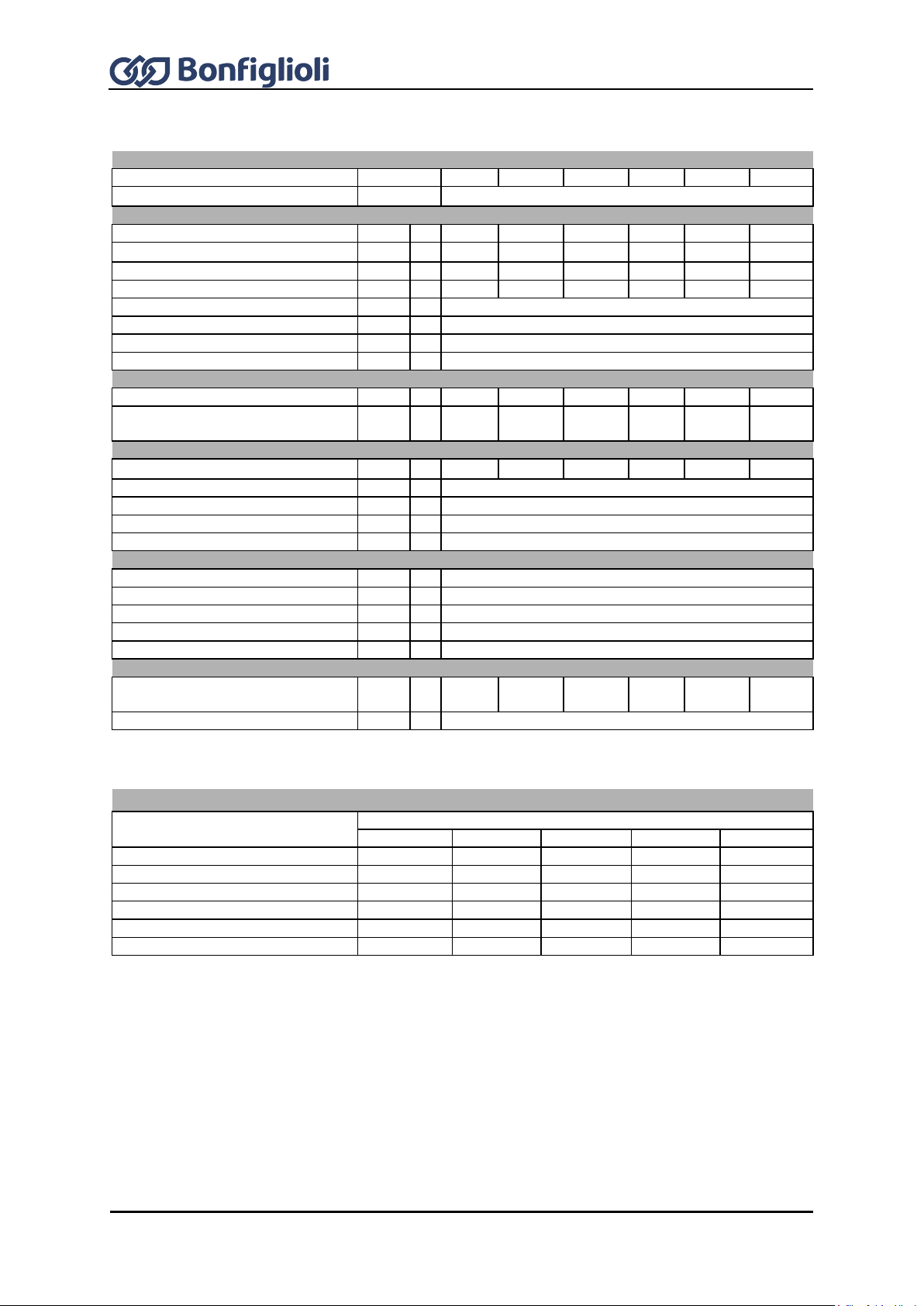
38
Operating Instructions ACU
12/16
Type
ACU 401
-01
-03
-05
-07
-09
-11
Size
1
Output, motor side
Recommended motor shaft power
P
kW
0.25
0.37
0.55
0.75
1.1
1.5
Output current
I A 1.0
1.6
1.8
2.4
3.2
3.8 3)
Long-term overload current (60 s)
I A 2.0
3.2
2.7
3.6
4.8
5.7
Short-time overload current (1 s)
I A 2.0
3.2
3.6
4.8
6.4
7.6
Output voltage
U
V
Maximum input voltage, three-phase
Protection
-
-
Short circuit / earth fault proof
Rotary field frequency
f
Hz
0 ... 599, depending on switching frequency
Switching frequency
f
kHz
2, 4, 8, 12, 16
Output, braking resistor
Min. braking resistance
R Ω 300
300
300
300
300
300
Recommended braking resistor
(U
dBC
= 770 V)
R Ω 930
930
930
634
462
300
Input, mains side
Power supply current
2)
I A 1.0
1.6
1.8
2.4
2.8 1)
3.3 1)
Mains voltage
U
V
320 ... 528
Mains frequency
f
Hz
45 ... 66
Fuses
I
A 6 UL type 600 VAC RK5
I
A
6
Mechanical
Dimensions
HxWxD
mm
190 x 60 x 175
Weight approx.
m
kg
1.2
Ingress protection rating
-
-
IP20 (EN60529)
Connection terminals
A
mm
2
0.2 ... 1.5
Form of assembly
-
-
vertical
Ambient conditions
Energy dissipation (2 kHz switching
frequency)
P W 30
35
40
46
58
68
Coolant temperature
T
n
°C
0 ... 40 (3K3 DIN IEC 721-3-3)
If required by the customer, the switching frequency may be increased if the output current is reduced at the
same time. Comply with the applicable standards and regulations for this operating point.
Output current 4)
Frequency inverter nominal power
Switching frequency
2 kHz
4 kHz
8 kHz
12 kHz
16 kHz
0.25 kW
1.0 A
1.0 A
1.0 A
0.8 A
0.7 A
0.37 kW
1.6 A
1.6 A
1.6 A
1.3 A
1.1 A
0.55 kW
1.8 A
1.8 A
1.8 A
1.5 A
1.2 A
0.75 kW
2.4 A
2.4 A
2.4 A
2.0 A
1.6 A
1.1 kW
3.2 A 1)
3.2 A 1)
3.2 A 1)
2.7 A 1)
2.2 A
1.5 kW 1)
3.8 A
3.8 A 3)
3.8 A 3)
3.2 A 3)
2.6 A 3)
5.6 ACU 401 Size 1 (0.25 to 1.5 kW, 400 V)
1)
Three-phase connection requires a commutating choke.
2)
Mains current with relative mains impedance ≥ 1% (see Chapter 7 "Electrical installation")
3)
Reduction of switching frequency in thermal limit range
4)
Maximum current in continuous operation
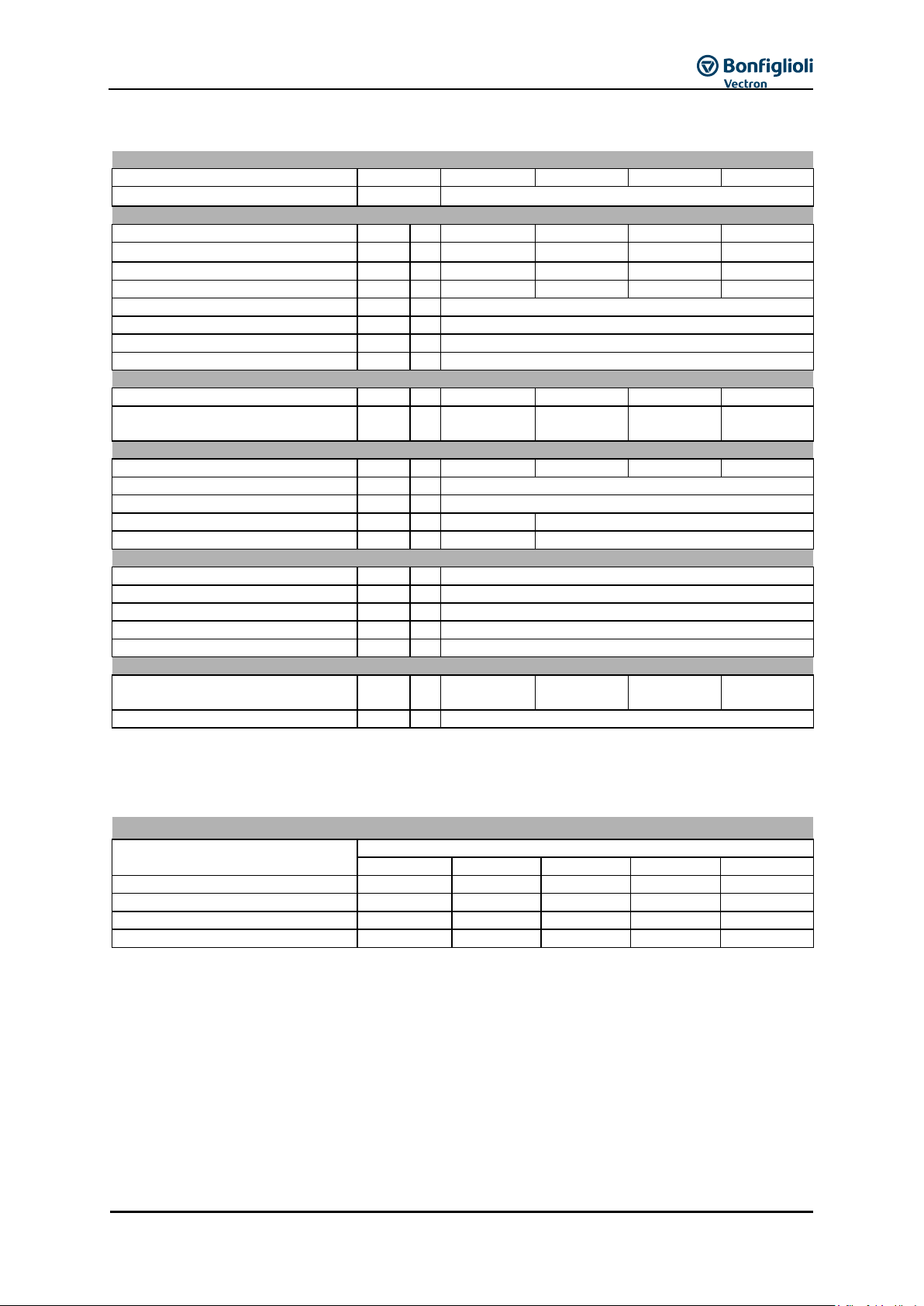
12/16
Operating Instructions ACU
39
Type
ACU 401 -12
-13
-15
-18
Size
2
Output, motor side
Recommended motor shaft power
P
kW
1.85
2.2
3.0
4.0
Output current
I A 4.2
5.8
7.8
9.0 3)
Long-term overload current (60 s)
I A 6.3
8.7
11.7
13.5
Short-time overload current (1 s)
I A 8.4
11.6
15.6
18.0
Output voltage
U
V
Maximum input voltage, three-phase
Protection
-
-
Short circuit / earth fault proof
Rotary field frequency
f
Hz
0 ... 599, depending on switching frequency
Switching frequency
f
kHz
2, 4, 8, 12, 16
Output, braking resistor
Min. braking resistance
R Ω 136
136
136
92
Recommended braking resistor
(U
dBC
= 770 V)
R Ω 300
220
148
106
Input, mains side
Power supply current 2)
I A 4.2
5.8
6.8 1)
7.8 1)
Mains voltage
U
V
320 ... 528
Mains frequency
f
Hz
45 ... 66
Fuses
I A 6
10
UL type 600 VAC RK5
I A 6
10
Mechanical
Dimensions
HxWxD
mm
250 x 60 x 175
Weight approx.
m
kg
1.6
Ingress protection rating
-
-
IP20 (EN60529)
Connection terminals
A
mm
2
0.2 ... 1.5
Form of assembly
-
-
vertical
Ambient conditions
Energy dissipation (2 kHz switching
frequency)
P W 68
87
115
130
Coolant temperature
T
n
°C
0 ... 40 (3K3 DIN IEC 721-3-3)
If required by the customer, the switching frequency may be increased if the output current is
reduced at the same time. Comply with the applicable standards and regulations for this operating
point.
Output current 4)
Frequency inverter nominal power
Switching frequency
2 kHz
4 kHz
8 kHz
12 kHz
16 kHz
1.85 kW
4.2 A
4.2 A
4.2 A
3.5 A
2.9 A
2.2 kW
5.8 A
5.8 A
5.8 A
4.9 A
3.9 A
3.0 kW
7.8 A
1)
7.8 A
1)
7.8 A
1)
6.6 A
1)
5.3 A
4.0 kW
9.0 A
1)
9.0 A
1) 3)
9.0 A
1) 3)
7.6 A
1) 3)
6.1 A
3)
5.7 ACU 401 Size 2 (1.85 to 4.0 kW, 400 V)
1)
Three-phase connection requires a commutating choke
2)
Mains current with relative mains impedance ≥ 1% (see Chapter 7 "Electrical installation")
3)
Reduction of switching frequency in thermal limit range
4)
Maximum current in continuous operation

40
Operating Instructions ACU
12/16
Type
ACU 401
-19
-21
-22
-23
-25
Size
3 4
Output, motor side
Recommended motor shaft power
P
kW
5.5
7.5
9.2
11.0
15.0
Output current
I A 14.0
18.0
22.0 3)
25.0
32.0
Long-term overload current (60 s)
I A 21.0
26.3
30.3
37.5
44.5
Short-time overload current (1 s)
I A 28.0
33.0
33.0
50.0
64.0
Output voltage
U
V
Maximum input voltage, three-phase
Protection
-
-
Short circuit / earth fault proof
Rotary field frequency
f
Hz
0 ... 599, depending on switching frequency
Switching frequency
f
kHz
2, 4, 8, 12, 16
Output, braking resistor
Min. braking resistance
R Ω 48
48
48
32
32
Recommended braking resistor
(U
dBC
= 770 V)
R Ω 80
58
48
48
32
Input, mains side
Power supply current 2)
I A 14.2
15.8 1)
20.0 1)
26.0
28.2 1)
Mains voltage
U
V
320 ... 528
Mains frequency
f
Hz
45 ... 66
Fuses I A
16
25
35
UL type 600 VAC RK5
I
A
20
30
40
Mechanical
Dimensions
HxWx
D
mm
250 x 100 x 200
250 x 125 x 200
Weight approx.
m
kg
3.0
3.7
Ingress protection rating
-
-
IP20 (EN60529)
Connection terminals
A
mm2
0.2 ... 6
0.2 ... 16
Form of assembly
-
-
vertical
Ambient conditions
Energy dissipation (2 kHz switching
frequency)
P W 145
200
225
240
310
Coolant temperature
Tn
°C
0 ... 40 (3K3 DIN IEC 721-3-3)
If required by the customer, the switching frequency may be increased if the output current is reduced at the
same time. Comply with the applicable standards and regulations for this operating point.
Output current 4)
Frequency inverter nominal power
Switching frequency
2 kHz
4 kHz
8 kHz
12 kHz
16 kHz
5.5 kW
14.0 A
14.0 A
14.0 A
11.8 A
9.5 A
7.5 kW
18.0 A 1)
18.0 A 1)
18.0 A 1)
15.1 A 1)
12.2 A
9.2 kW 1)
23.0 A
22.7 A
3)
22.0 A
3)
18.5 A 3)
15.0 A
3)
11 kW
25.0 A
25.0 A
25.0 A
21.0 A
17.0 A
15 kW
32.0 A 1)
32.0 A 1)
32.0 A 1)
26.9 A 1)
21.8 A
5.8 ACU 401 sizes 3 and 4 (5.5 to 15.0 kW, 400 V)
1)
Three-phase connection requires a commutating choke
2)
Mains current with relative mains impedance ≥ 1% (see Chapter 7 "Electrical installation")
3)
Reduction of switching frequency in thermal limit range
4)
Maximum current in continuous operation

12/16
Operating Instructions ACU
41
Type
ACU 401 -27
-29
-31
Size
5
Output, motor side
Recommended motor shaft power
P
kW
18.5
22.0
30.0
Output current
I A 40.0
45.0
60.0
Long-term overload current (60 s)
I A 60.0
67.5
90.0
Short-time overload current (1 s)
I A 80.0
90.0
120.0
Output voltage
U
V
Maximum input voltage, three-phase
Protection
-
-
Short circuit / earth fault proof
Rotary field frequency
f
Hz
0 ... 599, depending on switching frequency
Switching frequency
f
kHz
2, 4, 8
Output, braking resistor
Min. braking resistance
R
Ω
16
Recommended braking resistor
(U
dBC
= 770 V)
R Ω 26
22
16
Input, mains side
Power supply current 2)
I A 42.0
50.0
58.0 1)
Mains voltage
U
V
320 ... 528
Mains frequency
f
Hz
45 ... 66
Fuses I A
50
63
UL type 600 VAC RK5
I
A
50
60
Mechanical
Dimensions
HxWx
D
mm
250x200x260
Weight approx.
m
kg
8
Ingress protection rating
-
-
IP20 (EN60529)
Connection terminals
A
mm2
up to 25
Form of assembly
-
-
vertical
Ambient conditions
Energy dissipation (2 kHz switching
frequency)
P W 445
535
605
Coolant temperature
Tn
°C
0 ... 40 (3K3 DIN IEC 721-3-3)
If required by the customer, the switching frequency may be increased if the output current is reduced at the
same time. Comply with the applicable standards and regulations for this operating point.
Output current 3)
Frequency inverter nominal power
Switching frequency
2 kHz
4 kHz
8 kHz
18.5 kW
40.0 A
40.0 A
40.0 A
22 kW
45.0 A
45.0 A
45.0 A
30 kW
60.0 A 1)
60.0 A 1)
60.0 A 1)
5.9 ACU 401 Size 5 (18.5 to 30.0 kW, 400 V)
1)
Three-phase connection requires a commutating choke.
2)
Mains current with relative mains impedance ≥ 1% (see Chapter 7 "Electrical installation")
3)
Maximum current in continuous operation
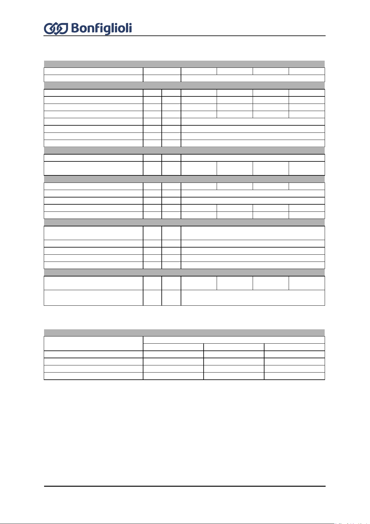
42
Operating Instructions ACU
12/16
Type
ACU 401 -33
-35
-37
-39
Size
6
Output, motor side
Recommended motor shaft power
P
kW
37.0
45.0
55.0
65.0
Output current
I A 75.0
90.0
110.0
125.0
Long-term overload current (60 s)
I A 112.5
135.0
165.0
187.5
Short-time overload current (1 s)
I A 150.0
180.0
220.0
250.0
Output voltage
U
V
Maximum input voltage, three-phase
Protection
-
-
Short circuit / earth fault proof
Rotary field frequency
f
Hz
0 ... 599, depending on switching frequency
Switching frequency
f
kHz
2, 4, 8
Output, braking resistor 5)
Min. braking resistance
R
Ω
7.5
Recommended braking resistor
(U
dBC
= 770 V)
R Ω 13
11 9 7.5
Input, mains side
Power supply current 2)
I A 87.0
104.0
105.0 1)
120.0 1)
Mains voltage
U
V
320 ... 528
Mains frequency
f
Hz
45 ... 66
Fuses I A
100
125
125
125
UL type 600 VAC RK5
I A 100
125
125
125
Mechanical
Dimensions
HxWx
D
mm
400x275x260
Weight approx.
m
kg
20
Ingress protection rating
-
-
IP20 (EN60529)
Connection terminals
A
mm2
up to 70
Form of assembly
-
-
vertical
Ambient conditions
Energy dissipation (2 kHz switching
frequency)
P W 665
830
1080
1255
Coolant temperature for air cooling
6)
Tn
°C
0 ... 40 (3K3 DIN IEC 721-3-3)
If required by the customer, the switching frequency may be increased if the output current is reduced at the
same time. Comply with the applicable standards and regulations for this operating point.
Output current 4)
Frequency inverter nominal power
Switching frequency
2 kHz
4 kHz
8 kHz
37 kW
75.0 A
75.0 A
75.0 A
45 kW
90.0 A
90.0 A
90.0 A
55 kW
110.0 A 1)
110.0 A 1)
110.0 A 1)
65 kW
125.0 A
1) 3)
125.0 A
1) 3)
125.0 A
1) 3)
5.10 ACU 401 Size 6 (37.0 to 65.0 kW, 400 V)
1)
Three-phase connection requires a commutating choke.
2)
Mains current with relative mains impedance ≥ 1% (see Chapter 7 "Electrical installation")
3)
Reduction of switching frequency in thermal limit range
4)
Maximum current in continuous operation
5)
As an option, the frequency inverter of this size is available without internal brake transistor.
6)
Coolant temperature for liquid cooling: see “Operating Instructions Liquid Cooling Supplemental“

12/16
Operating Instructions ACU
43
Type
ACU 401 -43
-45
-47
-49
Size
7
Output, motor side
Recommended motor shaft power
P
kW
75
90
110
132
Output current
I A 150
180
210
250
Long-term overload current (60 s)
I A 225
270
315
332
Short-time overload current (1 s)
I A 270
325
375
375
Output voltage
U
V
Maximum input voltage, three-phase
Protection
-
-
Short circuit / earth fault proof
Rotary field frequency
f
Hz
0 ... 599, depending on switching frequency
Switching frequency
f
kHz
2, 4, 8
Output, braking resistor
(external) 5)
Min. braking resistance
R
Ω
4.5
3.0
Recommended braking resistor
(U
dBC
= 770 V)
R Ω 6.1
5.1
4.1
3.8
Input, mains side
Power supply current 2)
I A 143 1)
172 1)
208 1)
249 1)
Mains voltage
U
V
320 ... 528
Mains frequency
f
Hz
45 ... 66
Fuses I A
160
200
250
315
Fuses as per UL6)
Cooper Bussmann
Type FWH-250A
FWH-300A
FWH-350A
FWH-400A
Mechanical
Dimensions
HxWx
D
mm
510 x 412 x 351
Weight approx.
m
kg
45
48
Ingress protection rating
-
-
IP20 (EN60529)
Connection terminals
A
mm2
up to 2 x 95
Form of assembly
-
-
vertical
Ambient conditions
Energy dissipation (2 kHz switching
frequency)
P W 1600
1900
2300
2800
Coolant temperature for air cooling
7)
Tn
°C
0 ... 40 (3K3 DIN IEC 721-3-3)
If required by the customer, the switching frequency may be increased if the output current is reduced at the
same time. Comply with the applicable standards and regulations for this operating point.
Output current 4)
Frequency inverter nominal power
Switching frequency
2 kHz
4 kHz
8 kHz
75 kW
150 A
150 A
150 A
90 kW
180 A
180 A
180 A
110 kW
210 A
210 A
210 A3)
132 kW
250 A
250 A
250 A3)
5.11 ACU 401 Size 7 (75.0 to 132.0 kW, 400 V)
1)
Three-phase connection requires a commutating choke.
2)
Mains current with relative mains impedance ≥ 1% (see Chapter 7 "Electrical installation")
3)
Reduction of switching frequency in thermal limit range
4)
Maximum current in continuous operation
5)
As an option, the frequency inverter of this size is available without internal brake transistor.
6)
For UL-compliant fusing, the specified Cooper Bussmann fuses must be used. Other fuses must not be used for
UL-conforming fusing.
7)
Coolant temperature for liquid cooling: see “Operating Instructions Liquid Cooling Supplemental“

44
Operating Instructions ACU
12/16
Installation height
100
85
60
40
20
55
45
3000
1000
2000 40003000
1000
2000
4000
Power reduction (Derating),
5%/1000 m above sea level,
h = 4000 m
max
max. coolant temperature,
3.3 °C/1000 m above sea level,
Mounting altitude in m above sea level Mounting altitude in m above sea level
Output current in %
Coolant temperature in °C
Coolant temperature
100
80
63
40
20
0 10
20
30
40 50 55
Power reduction (Derating)
2.5%/K upper 40 °C, T = 55 °C
max
Output current in %
Coolant temperature in °C
Mains voltage
100
83
63
40
20
0 400
420
440
460
480
Output current in %
Mains voltage equal output voltage in V
Reduction of output current at constant output power (Derating)
0.22%/ V upper 400 V, U = 480 V
max
5.12 Operation diagrams
The technical data of the frequency inverters refer to the nominal point which was selected to enable
a wide range of applications. A functionally and efficient dimensioning (derating) of the frequency
inverters is possible based on the following diagrams.

12/16
Operating Instructions ACU
45
46
Operating Instructions ACU
12/16
WARNING
To avoid serious physical injuries or major material damage, only qualified persons are
allowed to work on the device.
WARNING
During assembly, make sure that no foreign particles (e.g. chips, dust, wires, screws,
tools) can get inside the frequency inverter. Otherwise there is the risk of short circuits
and fire.
The frequency inverter complies with IP20 ingress protection rating only if the covers,
components and terminals are mounted properly.
Overhead installation or installation in horizontal position is not permissible.
In devices with liquid cooling the coolant hoses must be connected after the mechanical
installation procedure. Comply with instructions in the "Operating Instructions Liquid
Cooling Supplemental" document.
NOTICE
Mount the devices with sufficient clearance to other components so that the cooling air
can circulate freely. Avoid soiling by grease and air pollution by dust, aggressive gases,
etc.
Fan inlet and outlet openings must not be covered.
6 Mechanical installation
As a standard, the frequency inverters of ingress protection rating IP20 are designed for stationary
installation in electrical cabinets.
Apart from the air-cooled standard installation variant described in these Operating Instructions other
installation variants are available:
Feedthrough assembly for sizes 1 through 8, see "Installation Instructions – Feedthrough
Assembly"
ColdPlate for sizes 1 through 5, see "Installation Instructions – ColdPlate"
Liquid cooling for sizes 6 through 8, see “Operating Instructions Liquid Cooling Supplemental”
During installation, comply with the installation and the safety instructions and note the device
specifications.
6.1 Air circulation
6.2 Sizes 1 and 2: ACU 201 (up to 3.0 kW) and 401 (up to 4.0 KW)
The frequency inverter is mounted in a vertical position on the assembly panel by means of the
standard fittings. The following illustration shows the different mounting possibilities.
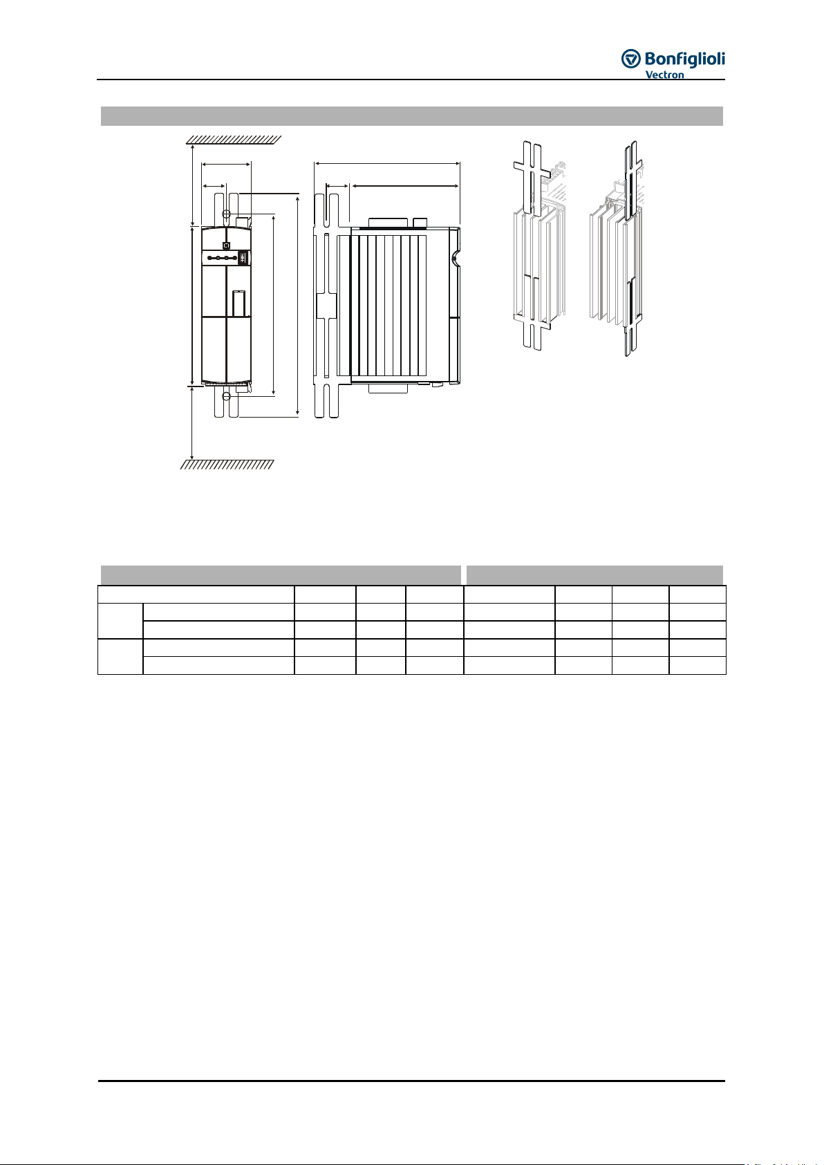
12/16
Operating Instructions ACU
47
Standard installation
b
b1
a1
a a2
c
c1
x
x
x 100 mm
b1
Dimensions [mm]
Assembly dimensions [mm]
ACU
a b c
a1
a2
b1
c1
201
0.25 kW ... 1.1 kW
190
60
178
210 ... 230
260
30
133
1.5 kW ... 3.0 kW
250
60
178
270 ... 290
315
30
133
401
0.25 kW ... 1.5 kW
190
60
178
210 ... 230
260
30
133
1.85 kW ... 4.0 kW
250
60
178
270 ... 290
315
30
133
For assembly the long side of the fixing plate is inserted in the heat sink and screwed to the assembly
panel.
The dimensions of the device and the installation dimensions are those of the standard device without
optional components and are given in millimeters.
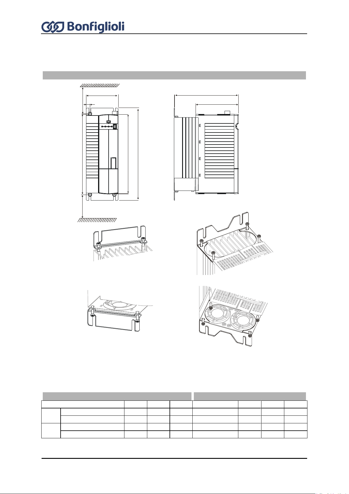
48
Operating Instructions ACU
12/16
The frequency inverter is mounted in a vertical position on the assembly panel by means of the
standard fittings. The following illustration shows the standard fitting.
Standard installation
b
b1
aa1 a2
c
x
x
c1
x 100 mm
fixing bracket bottom
(fixing with screws ) M4x60
fixing bracket top
(fixing with screws ) M4x20
For assembly the two fixing brackets are screwed to the heat sink of the frequency inverter and the
assembly panel.
The frequency inverters are provided with fixing brackets, which are fitted using four thread-cutting
screws. The dimensions of the device and the installation dimensions are those of the standard
device without optional components and are given in millimeters.
Dimensions [mm]
Assembly dimensions [mm]
ACU a b c a1
a2
b1
c1
201
4.0 … 5.5 kW
250
100
200
270 ... 290
315
12
133
7.5 … 9.2 kW
250
125
200
270 ... 290
315
17.5
133
401
5.5 ... 9.2 kW
250
100
200
270 ... 290
315
12
133
11.0 … 15.0 kW
250
125
200
270 ... 290
315
17.5
133
6.3 Sizes 3 and 4: ACU 201 (4.0 to 9.2 kW) and 401 (5.5 to 15.0 kW)

12/16
Operating Instructions ACU
49
The frequency inverter is mounted in a vertical position on the assembly panel by means of the
standard fittings. The following illustration shows the standard fitting.
Standard installation
c
c1
x 100 mm
x
a
a1
a2
b
b1
x
fixing bracket top
(fixing with screws ) M4x20
fixing bracket bottom
(fixing with screws ) M4x70
For assembly the two fixing brackets are screwed to the heat sink of the frequency inverter and the
assembly panel.
The frequency inverters are provided with fixing brackets, which are fitted using four thread-cutting
screws. The dimensions of the device and the installation dimensions are those of the standard
device without optional components and are given in millimeters.
Dimensions [mm]
Assembly dimensions [mm]
ACU a b c a1
a2
b1
c1
401
18.5...30.0 kW
250
200
260
270 … 290
315
20
160
6.4 Size 5: ACU 401 (18.5 to 30.0 kW)

50
Operating Instructions ACU
12/16
For mechanical installation of liquid-cooled size 6 frequency inverters see “Operating
Instructions Liquid Cooling Supplemental”.
Standard installation
fixing braket top
(fixing with screws ) M5x20
fixing braket bottom
(fixing with screws )M5x20
aa1a2
x
x 100 mm
b
b1
x
c
c1
Dimensions [mm]
Assembly dimensions [mm]
ACU
a b c
a1
a2
b1
c1
401
37...65 kW
400
275
260
425 … 445
470
20
160
6.5 Size 6: ACU 401 (37.0 to 65.0 kW) (air-cooled)
The frequency inverter is mounted in a vertical position on the assembly panel by means of the
standard fittings. The following illustration shows the standard fitting.
For assembly the two fixing brackets are screwed to the heat sink of the frequency inverter and the
assembly panel.
The frequency inverters are provided with fixing brackets, which are fitted using four thread-cutting
screws. The dimensions of the device and the installation dimensions are those of the standard device
without optional components and are given in millimeters.
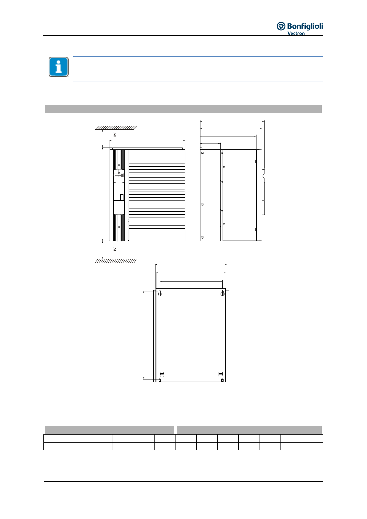
12/16
Operating Instructions ACU
51
The illustration shows an example for mechanical installation of air-cooled frequency
inverters. The dimensions and fitting elements correspond to those of liquid-cooled size 7
devices.
The frequency inverter is mounted in a vertical position on the assembly panel. The following
illustration shows the standard fitting.
Standard installation
The diameter of the fixing holes is 9 mm.
For assembly the back wall of the frequency inverter is screwed to the assembly panel.
The dimensions of the device and the installation dimensions are those of the standard device
without optional components and are given in millimeters.
Dimensions [mm]
Assembly dimensions [mm]
ACU a b c a1
b1
b2
b3
c1
c2
c3
401
75...132 kW
510
412
351
480
392
382
342
338
305
110
a
b
c
c1
c2
c3
b1
b2
b3
a1
x
x
x
300 mm
x
300 mm
6.6 Size 7: ACU 401 (75.0 to 132.0 kW)

52
Operating Instructions ACU
12/16
WARNING
The electrical installation must be carried out by qualified electricians according to the
general and regional safety and installation directives.
The documentation and device specification must be complied with during installation.
Before any assembly or connection work, discharge the frequency inverter. Verify safe
isolation from power supply.
When the frequency inverter is disconnected from power supply, the mains, DC-link
voltage and motor terminals may still be live for some time. Work on the device may
only be started once the DC link capacitors have discharged. The time to wait is at least
3 minutes in the case of sizes 1 through 7.
Do not connect inappropriate voltage sources. The nominal voltage of the frequency
inverter must correspond to the supply voltage.
The frequency inverter must be connected to ground potential.
Do not remove any covers of the frequency inverter while power supply is on.
CAUTION
IP20 ingress protection rating is only achieved with terminals plugged and properly
mounted covers.
7 Electrical installation
The connecting cables must be protected externally, considering the maximum voltage and current
values of the fuses. The mains fuses and cable cross-sections are to be selected according to
EN 602041 and DIN VDE 0298 Part 4 for the nominal operating point of the frequency inverter.
According to UL/CSA, the frequency inverter is suitable for operation at a supply network of a
maximum of 480 VAC which delivers a maximum symmetrical current of 5000 A (effective value) if
protected by fuses of class RK5. Only use copper cables with a temperature range of 60 / 75 °C.
The frequency inverters are to be grounded properly, i.e. large connection area and with good
conductivity. The leakage current of the frequency inverters may exceed AC 3.5 mA or DC 10 mA.
According to EN 61800-5-1 a permanent connection must be provided. The protective conductor
cross-section required for grounding the fixing plate must be selected according to the size of the unit.
In these applications, the cross-section must correspond to the recommended cross-section of the
wire.
Special connection variants are possible apart from the standard connection variant described in these
Operating Instructions:
Parallel connection (see "Application Manual – Parallel Connection")
DC supply (if you have any questions on this, contact BONFIGLIOLI Customer Service.)
Connection Conditions
The frequency inverter is suited for connection to the public or industrial supply mains according
to the technical data. If the transformer output of the supply mains is ≤ 500 kVA, a mains
commutation choke is only necessary for the frequency inverters identified in the technical data.
The other frequency inverters are suitable for connection without a mains commutating choke
with a relative mains impedance 1%.
Check, based on the specifications of EN 61000-3-2, if the devices can be connected to the public
supply means without taking additional measures. The frequency inverters ≤ 9.2 kW with
integrated EMC filter comply with the emission limits of the product standard EN 61800-3 up to a
motor cable length of 10 m, without additional measures being required. Increased requirements
in connection with the specific application of the frequency inverter are to be met by means of
optional components. Commutating chokes and EMC filters are optionally available for the series
of devices.

12/16
Operating Instructions ACU
53
WARNING
Please note (according to EN61800-5-1): This product may cause direct current in the
protective earth conductor. Where residual current devices (RCD) or residual current
monitors (RCM) are used as a protection against direct or indirect contact, only RCDs /
RCMs of Type B are permissible on the power supply side of this product.
Operation on an unearthed mains (IT mains) is admissible after disconnection of the Y capacitors
in the interior of the device. For disconnection of the Y capacitors, please contact
BONFIGLIOLI.
Interference-free operation with residual current device is guaranteed at a tripping current 30
mA if the following points are observed:
One-phase power supply (L1/N): Pulse current and alternating current sensitive residual
current devices (Type A to EN 61800-5-1)
Two-phase power supply (L1/L2) or Three-phase power supply (L1/L2/L3):
All-current sensitive residual current devices (Type B to EN 61800-5-1)
Use EMC filters with reduced leakage current or, if possible, do not use EMC filters at all.
The length of the shielded motor cable is ≤ 10 m and there are no additional capacitive
components between the mains or motor cables and PE.
The fuses to be used are to be selected depending on the specific application. The safety
recommendations in the Technical Data are valid for continuous operation without overload.

54
Operating Instructions ACU
12/16
1 fuse
2 circuit breaker
3 line choke (optional)
4 input filter (optional)
5 cable shield
6 braking resistor (optional)
7 output filter (optional)
7.1 EMC information
The frequency inverters are designed according to the requirements and limit values of product norm
EN 61800-3 with an interference immunity factor (EMI) for operation in industrial applications.
Electromagnetic interference is to be avoided by expert installation and observation of the specific
product information.
Measures
Install the frequency inverters and commutating chokes on a metal mounting panel. Ideally, the
mounting panel should be galvanized, not painted.
Provide proper equipotential bonding within the system or plant. Plant components such as
electrical cabinets, control panels, machine frames must be connected by means of PE cables, i.e.
sufficient area and with good conductivity.
The shield of the control cables is to be connected to ground potential properly, i.e. with good
conductivity, on both sides (shield clamp). Mount shield clamps for cable shields close to the unit.
Connect the frequency inverter, the commutating choke, external filters and other components to
an earthing point via short cables.
Excessive cable length and loosely suspended cabling must be avoided.
Contactors, relays and solenoids in the electrical cabinet are to be provided with suitable
interference suppression components.

12/16
Operating Instructions ACU
55
A
Mains connection
The length of the mains supply cable is not limited. However, it
must be installed separate from the control, data and motor
cables.
B
DC-link connection
The frequency inverters are to be connected to the same mains
potential or a common direct voltage source. Cables longer than
300 mm are to be shielded. The shield must be connected to the
mounting panel on both sides.
C
Control connection
Keep control and signal cables physically separate from the
power cables. Analog signal lines are to be connected to the
shield potential on one side. Install sensor cables separate from
motor cables.
D
Motor and braking resistor
The shield of the motor cable is to be connected to ground
potential properly on both sides. On the motor side use a metal
compression gland. On the frequency inverter side an
appropriate shield clamp is to be used. The signal cable used for
monitoring the motor temperature must be kept separate from
the motor cable. Connect the shield of this line on both sides. If
a braking resistor is used, the connection cable must also be
shielded, and the shield is to be connected to earth potential on
both sides.
Relay
The relay enables using high-energy signals.
Line choke
Line chokes reduce mains harmonics and reactive power. In addition, a longer service life of the
frequency inverter is possible. When using a line choke, note that line chokes may reduce the
maximum output voltage of the frequency inverter.
The line choke must be installed between the mains connection and the input filter.
Input filter
Input filters reduce grid-bound, high-frequency radio interference voltage.
Install the input filter on the mains side upstream of the frequency inverter.
CAUTION
The frequency inverters meet the requirements of the low-voltage directive
2006/95/EC and the requirements of the EMC directive 2004/108/EC. The EMC
product standard EN 61800-3 relates to the drive system. The documentation
provides information on how the applicable standards can be complied if the
frequency inverter is a component of the drive system. The declaration of conformity
is to be issued by the supplier of the drive system.

56
Operating Instructions ACU
12/16
A
Relay connection S3OUT
Change-over contact, response time approx. 40 ms,
Make contact AC 5 A / 240 V, DC 5 A (ohmic) / 24 V
Break contact AC 3 A / 240 V, DC 1 A (ohmic) / 24 V
B
Voltage output/input
Bidirectional, DC 20 V voltage output (I
max
=180 mA) or input for external power supply DC 24 V
±10%
C
Digital input S1IND/STOA
Digital signal, STOA (1st shut-down path for safety function STO – “Safe Torque Off”), response
time: approx. 10 ms (On), 10 μs (Off), U
max
= DC 30 V, 10 mA at DC 24 V, PLC compatible
D
Digital inputs S2IND ... S6IND
Digital signal: Response time approx. 2 ms, U
max
= DC 30 V, 10 mA at 24 V, PLC compatible,
frequency signal: DC 8...30 V, 10 mA at DC 24 V, f
max
= 150 kHz
E
Digital input S7IND/STOB
Digital signal, STOB (2nd shut-down path for safety function STO – “Safe Torque Off”), response
time: approx. 10 ms (on), 10 μs (off), U
max
= DC 30 V,
10 mA at DC 24 V, PLC compatible
F
Digital output S1OUT
Digital signal, DC 24 V, I
max
= 50 mA, PLC compatible, overload and short-circuit proof
Multifunction Output MFO1
Analog signal: DC 24 V, I
max
= 50 mA, pulse-width modulated, f
PWM
= 116 Hz,
Digital signal: DC 24 V, I
max
= 50 mA, PLC compatible,
Frequency signal: DC 0...24 V, I
max
= 40 mA, f
max
= 150 kHz,
overload and short-circuit proof
Multifunction input MFI1
Analog signal: Resolution 12 bit, DC 0...10 V (Ri = 70 k), 0…20 mA (Ri = 500 ),
Digital signal: Response time approx. 4 ms, U
max
= DC 30 V, 4 mA at DC 24 V,
PLC compatible
+10 V / 4 mA
MFI1
GND 10 V
6
X210A
+20 V / 180 mA
24 V
S7IND
S4IND
X210B
5
6
7
1
2
3
S3OUT
X10
A
D
5
S3IND
4
S2IND
2
S1IND
7
S5IND
3
1
1
S6IND
GND 20 V
2
4
MFO1
S1OUT
3
+
-
L2 L3L1
X1
VWU
Rb1
X2
+
-
Rb2
I
U, I
A
B
C
D
E
F
G
H
7.2 Block diagram

12/16
Operating Instructions ACU
57
WARNING
The hardware modules at slots B and C may only be assembled and disassembled
after the frequency inverter has been disconnected safely from power supply. Work
on the device may only be started once the DC link capacitors have discharged. The
discharge time is at least 3 minutes in the case of sizes 1 through 7.
The unit may only be connected with the power supply switched off.
Verify safe isolation from power supply.
Hardware modules
A
B
C
A
Control unit KP500
Connection of the optional control unit KP500 or an interface adapter
KP232.
B
Communication module CM
Slot for connection to various communication protocols:
CM-232: RS232 interface
CM-485: RS485 interface
CM-PDP: Profibus-DP interface
CM-CAN: CANopen interface
Other communication modules, see Chapter 1.1 "Instruction
Manuals".
C
Extension module EM
Slot for customer-specific adaptation of the control inputs and outputs to
various applications:
EM-ENC: extended speed sensor evaluation
EM-RES: Resolver evaluation
EM-ABS: Absolute encoder evaluation
EM-IO, analog and digital inputs and outputs
EM-SYS: System Bus
(system bus in combination with CM-CAN communication module upon
request)
CAUTION
If two optional components with CAN-Protocol controller are installed, the system bus
interface in the EM extension module is deactivated!
7.3 Optional components
Due to modular hardware components, the frequency inverters can be integrated in the automation
concept easily. The standard and optional modules are recognized during the initialization, and the
controller functionality is adjusted automatically. For the information required for installation and
handling of the optional modules, refer to the corresponding documentation.

58
Operating Instructions ACU
12/16
HINWEIS
The fuses must be chosen depending on the individual application. The values
recommended in the technical Data apply for the continuos rated operation without
overload.
Mains cable
Protective conductor
Mains cable up to 10 mm²
Install two protective conductors of the same size as the mains
cable, or one protective conductor of a size of 10 mm².
Mains cable 10…16 mm²
Install one protective conductor of the same size as the mains
feeder.
Mains cable 16…35 mm²
Install one protective conductor of a size of 16 mm².
Mains cable > 35 mm²
Install one protective conductor of half the size of the mains feeder.
201
Mains cable
PE-conductor
Motor cable
-01
-03
-05
-07
-09
0
.25 kW
0.37 kW
0.55 kW
0.75 kW
1.1 kW
1.5 mm²
2x1.5 mm² or
1x10 mm²
1.5 mm²
-11
-13
-15
1.5 kW
2.2 kW
3 kW
2.5 mm²
2x2.5 mm² or
1x10 mm²
1.5 mm²
-18
4 kW
4 mm²
2x4 mm² or
1x10 mm²
4 mm²
7.4 Connection of Unit
7.4.1 Dimensioning of conductor cross-section
The connecting cables must be protected externally, considering the maximum voltage and maximum
current values of the fuses. The line fuses and cable cross-sections must be dimensioned according to
EN 602041 and DIN VDE 0298 Part 4 for the nominal operating point of the frequency inverter.
The cable dimensions should be selected according to the current load and voltage drop to be
expected. Select the cable cross-section of the cables such that the voltage drop is as small as
possible. If the voltage drop is too great, the motor will not reach its full torque. Also comply with any
additional national and application-specific regulations and the separate UL instructions. For typical
mains fuses, refer to chapter 5 "Technical data".
According to EN61800-5-1, the cross-sections of the PE conductor shall be dimensioned as follows:
The following tables provide an overview of typical cable cross-sections (copper cable with PVC
insulation, 30 °C ambient temperature, continuous mains current max. 100% rated input current,
installation variant C). Actual mains cable cross-section requirements may deviate from these values
depending on actual operating conditions.
7.4.1.1 Typical cross-sections Size 1 through 7 (0.25 kW … 132 kW)
The following tables provide an overview of typical cable cross-sections (copper cable with PVC
insulation, 30 °C ambient temperature, continuous mains current max. 100% rated input current,
installation variant B2). Actual mains cable cross-section requirements may deviate from these values
depending on actual operating conditions.
230 V: One-phase (L/N) and two-phase (L1/L2) connection

12/16
Operating Instructions ACU
59
201
Mains cable
PE-conductor
Motor cable
-01
-03
-05
-07
-09
-11
-13
-15
0.25 kW
0.37 kW
0.55 kW
0.75 kW
1.1 kW
1.5 kW
2.2 kW
3 kW
1.5 mm²
2x1.5 mm² or 1x10
mm²
1.5 mm²
-18
-19
4 kW
5.5 kW
4 mm²
2x4 mm² or 1x10
mm²
4 mm²
-21
7.5 kW
6 mm²
2x6 mm² or 1x10
mm²
6 mm²
-22
9.2 kW
10 mm²
1x10 mm²
10 mm²
401
Mains cable
PE-conductor
Motor cable
-01
-03
-05
-07
-09
-11
-12
-13
-15
-18
0.25 kW
0.37 kW
0.55 kW
0.75 kW
1.1 kW
1.5 kW
1.85
2.2 kW
3 kW
4 kW
1.5 mm²
2x1.5 mm² or 1x10
mm²
1.5 mm²
-19
-21
5.5 kW
7.5 kW
2.5 mm²
2x2.5 mm² or 1x10
mm²
2.5 mm²
-22
-23
9.2 kW
11 kW
4 mm²
2x4 mm² or 1x10
mm²
4 mm²
-25
15 kW
6 mm²
2x6 mm² or 1x10
mm²
6 mm²
-27
18.5 kW
10 mm²
1x10 mm²
10 mm²
-29
-31
22 kW
30 kW
16 mm²
1x16 mm²
16 mm²
-33
37 kW
35 mm²
1x16 mm²
25 mm²
-35
45 kW
50 mm²
1x25 mm²
35 mm²
-37
55 kW
50 mm²
1x25 mm²
50 mm²
-39
65 kW
70 mm²
1x35 mm²
70 mm²
-43
75 kW
70 mm²
1x50 mm²
95 mm²
-45
90 kW
95 mm²
1x70 mm²
2x70 mm²
-47
110 kW
2x70 mm²
1x70 mm²
2x70 mm²
-49
132 kW
2x70 mm²
1x70 mm²
2x70 mm²
230 V: Three-phase connection (L1/L2/L3)
400V: Three-phase connection (L1/L2/L3)
60
Operating Instructions ACU
12/16
DANGER
Disconnect the frequency inverter from mains voltage and protect it against being
energized unintentionally.
Verify safe isolation from power supply.
Work on the device may only be started once the DC link capacitors have discharged.
The time to wait is at least 3 minutes in the case of sizes 1 through 7.
When the frequency inverter is disconnected from power supply, the mains, DC-link
voltage and motor terminals may still be live for some time.
CAUTION
The control, mains and motor lines must be kept physically separate from one another.
The cables connected to the frequency inverters may not be subjected to high-voltage
insulation tests unless appropriate circuitry measures are taken before.
DANGER
Disconnect the frequency inverter from mains voltage and protect it against being
energized unintentionally.
Verify safe isolation from power supply.
Work on the device may only be started once the DC link capacitors have discharged.
The time to wait is at least 3 minutes in the case of sizes 1 through 7.
When the frequency inverter is disconnected from power supply, the mains, DC-link
voltage and motor terminals may still be live for some time.
7.4.2 Mains connection
The mains fuses and cable cross-sections are to be selected according to EN 602041 and DIN VDE
0298 Part 4 for the nominal operating point of the frequency inverter. According to UL/CSA, approved
Class 1 copper lines with a temperature range of 60/75 °C and matching mains fuses are to be used
for the power cables. The electrical installation is to be done according to the device specifications and
the applicable standards and directives.
7.4.3 Motor connection
Bonfiglioli Vectron MDS GmbH recommends using shielded cables for the connection of the motor and
the braking resistor to the frequency inverter. The shield is to be connected to PE potential properly,
i.e. with good conductivity, on both sides. The control, mains and motor lines must be kept physically
separate from one another. The user must comply with the applicable limits stipulated in the relevant
national and international directives as regards the application, the length of the motor cable and the
switching frequency.
12/16
Operating Instructions ACU
61
Permissible length of motor cable without output filter
Frequency inverter
unshielded cable
shielded cable
0.25 kW … 1.5 kW
50 m
25 m
1.85 kW … 4.0 kW
100 m
50 m
5.5 kW … 9.2 kW
100 m
50 m
11.0 kW … 15.0 kW
100 m
50 m
18.5 kW … 30.0 kW
150 m
100 m
37.0 kW … 65.0 kW
150 m
100 m
75.0 kW … 132.0 kW
150 m
100 m
160.0 kW … 400.0 kW
150 m
100 m
The specified lengths of the motor cables must not be exceeded if no output filter is installed.
Frequency inverters ≤ 9.2 kW with integrated EMC filter comply with the emission
limits stipulated in EN 61800-3 if the motor cable is no longer than 10 m. Frequency
inverters ≤ 9,2 kW of Design 3 with integrated EMC filter comply with EN 61800-3 if
the motor cable is no longer than 20m. Customer-specific requirements can be met
using an optional filter.
Longer motor cables can be used after taking appropriate technical measures, e.g. use of lowcapacitance cables and output filters. The following table contains recommended values for the use
of output filters.
Motor cable length with output filter
Frequency inverter
unshielded cable
shielded cable
0.25 kW … 1.5 kW
upon request
upon request
1.85 kW … 4.0 kW
150 m
100 m
5.5 kW … 9.2 kW
200 m
135 m
11.0 kW … 15.0 kW
225 m
150 m
18.5 kW … 30.0 kW
300 m
200 m
37.0 kW … 65.0 kW
300 m
200 m
75.0 kW … 132.0 kW
300 m
200 m
160.0 kW … 400.0 kW
300 m
200 m
7.4.3.1 Length of motor cables, without filter
7.4.3.2 Motor cable length, with output filter dU/dt
7.4.3.3 Motor cable length, with sinus filter
Motor cables can be much longer if sinus filters are used. By conversion in sinus-shaped currents,
high-frequency portions which might limit the cable length are filtered out. Also consider the voltage
drop across the cable length and the resulting voltage drop at the sinus filter. The voltage drop results
in an increase of the output current. Check that the frequency inverter can deliver the higher output
current. This must be considered in the projecting phase already.
If the motor cable length exceeds 300 m, please consult BONFIGLIOLI.
7.4.3.4 Group drive
In the case of a group drive (several motors at one frequency inverter), the total length shall be
divided across the individual motors according to the value given in the table. Please note that group
drive with synchronous servomotors is not possible.
Use a thermal monitoring element on each motor (e.g. PTC resistor) in order to avoid damage.
7.4.3.5 Speed sensor connection
Install sensor cables physically separate from motor cables. Comply the sensor manufacturer's
specifications.

62
Operating Instructions ACU
12/16
DANGER
Disconnect the frequency inverter from mains voltage and protect it against being
energized unintentionally.
Verify safe isolation from power supply.
Work on the device may only be started once the DC link capacitors have discharged.
The time to wait is at least 3 minutes in the case of sizes 1 through 7.
When the frequency inverter is disconnected from power supply, the mains, DC-link
voltage and motor terminals may still be live for some time.
WARNING
The surface of the braking resistor may reach a high temperature during operation and
may remain hot for some time after operation. Do not touch the braking resistor while
the frequency inverter is in operation or ready for operation. Non-compliance may result
in burns. Install a safeguard to prevent touching or provide a warning sign.
Do not install the braking resistor near inflammable or heat-sensitive materials.
Do not cover the braking resistor.
CAUTION
Bonfiglioli Vectron MDS GmbH recommends using a temperature switch. Depending on
the resistor selected, the temperature switch is integrated as a standard or available as
an option. The temperature switch disconnects the frequency inverter from mains
supply if the braking resistor is overloaded.
Using braking resistors without temperature switches may result in critical situations.
Limit the length of the braking resistor cables to the necessary minimum.
L1
L2
L3
K1
K1
R
b
T1
Rb1 Rb2
T2
Rb2Rb1
X2
X1
Connect the shield close to the frequency inverter and limit the length to the necessary minimum.
7.4.4 Connection of a braking resistor
Install a braking resistor if feedback of regenerative energy is expected. Overvoltage shutdowns can
be avoided by this.
Braking resistors are connected via terminal X2.

12/16
Operating Instructions ACU
63
DANGER
Disconnect the frequency inverter from mains voltage and protect it against being
energized unintentionally.
Verify safe isolation from power supply.
Work on the device may only be started once the DC link capacitors have discharged.
The time to wait is at least 3 minutes in the case of sizes 1 and 2.
When the frequency inverter is disconnected from power supply, the mains, DC-link
voltage and motor terminals may still be live for some time.
Switch off power supply before connecting or disconnecting the keyed plug-in
terminals X1 and X2 .
Mains connection ACU 201 (up to 3.0 kW) and 401 (up to 4.0 kW)
1
With a mains current above 10 A, the mains power connection 230 V 1ph/N/PE and the
mains power connection 230 V 2ph/N/PE are to be done on two terminals.
X1
1ph / 230V AC
+
-
L1
L2 L3L1
N PE
3ph / 230V AC
3ph / 400V AC
+
-
L1
L2 L3L1
L2 L3 PE
2ph / 230V AC
+
-
L1 L2 PE
L2 L3L1
250 W ... 1.1 kW
Phoenix ZEC 1,5/ .. ST7,5
0.2 ... 1.5 mm
AWG 24 ... 16
2
0.2 ... 1.5 mm
AWG 24 ... 16
2
0.25 ... 1.5 mm
AWG 22 ... 16
2
0.25 ... 1.5 mm
AWG 22 ... 16
2
2ph / 230V AC1ph / 230V AC
1.5 kW ... 3.0 kW
L1 N PE
+
- L1 L2 L3L1
3ph / 230V AC
3ph / 400V AC
PE
1.5 kW ... 3.0 kW 1.5 kW ... 4.0 kW
+
-
L1 L2 L3L1
L1 L2 PE L1
+
-
L1 L2 L3L1
L2 L3
7.5 Connection by size
7.5.1 Sizes 1 and 2: ACU 201 (up to 3.0 kW) and 401 (up to 4.0 kW)
Frequency inverters are connected to mains via plug-in terminal X1. The motor and braking resistor
are connected to the frequency inverter via plug-in terminal X2. IP20 ingress protection rating
(EN60529) is only guaranteed with the terminals plugged.
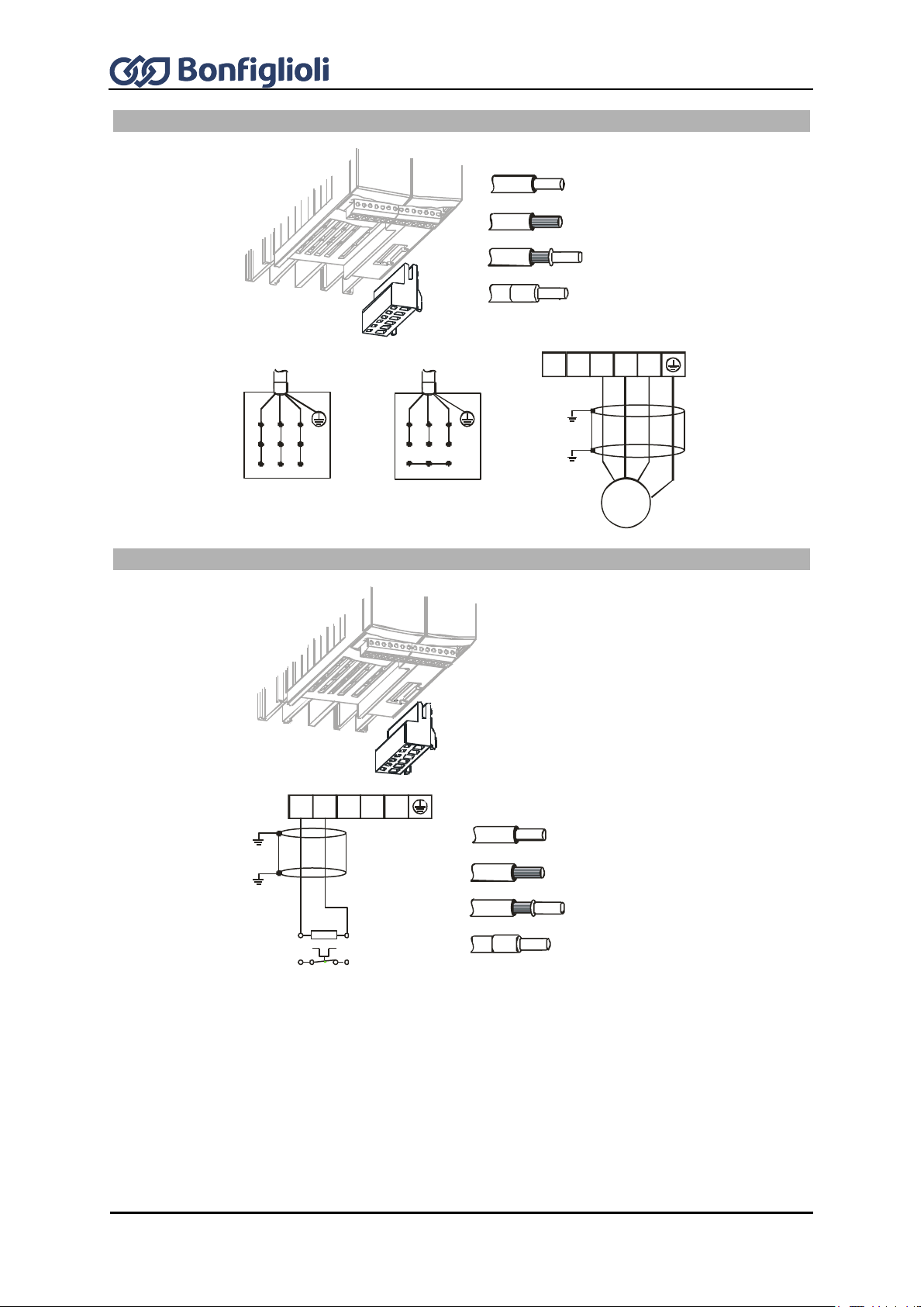
64
Operating Instructions ACU
12/16
Motor connection ACU 201 (up to 3.0 kW) and 401 (up to 4.0 kW)
Phoenix ZEC 1,5/ .. ST7,5
0.2 … 1.5 mm
AWG 24 … 16
2
0.2 … 1.5 mm
AWG 24 … 16
2
0.25 … 1.5 mm
AWG 22 … 16
2
0.25 … 1.5 mm
AWG 22 … 16
2
X2
Star connection
V W
U
Delta connection
V W
U
V WU
Rb2Rb1
M
3~
Connection of brake resistor with temperature switch
X2
V W
URb2Rb1
R
b
T1
Rb1 Rb2
T2
X2
Phoenix ZEC 1,5/ .. ST7,5
0.2 … 1.5 mm
AWG 24 … 16
2
0.2 … 1.5 mm
AWG 24 … 16
2
0.25 … 1.5 mm
AWG 22 … 16
2
0.25 … 1.5 mm
AWG 22 … 16
2

12/16
Operating Instructions ACU
65
DANGER
Disconnect the frequency inverter from mains voltage and protect it against being
energized unintentionally.
Verify safe isolation from power supply.
Work on the device may only be started once the DC link capacitors have discharged.
The time to wait is at least 3 minutes in the case of sizes 3 and 4.
When the frequency inverter is disconnected from power supply, the mains, DC-link
voltage and motor terminals may still be live for some time.
Switch off power supply before connecting or disconnecting the mains cable to/from
terminal X1, the motor cables and the brake resistor to/from terminal X2.
Mains connection ACU 201 (4.0 to 9.2 kW) and 401 (5.5 to 15.0 kW)
ACU 201-18 (4,0 kW): one and three-phase connection possible
ACU 201-19 (5,5 kW) and higher: three-phase connection possible
0.2 … 6 mm
AWG 24 … 10
2
4.0 kW … 9.2 kW
6qmm / RM7,5
0.2 … 6 mm
AWG 24 … 10
2
0.25 … 4 mm
AWG 22 … 12
2
0.25 … 4 mm
AWG 22 … 16
2
X1
0.2 … 16 mm
ACTIVE Cube 201-18 (4.0 kW):
AWG 24 … 6
2
11 kW … 15 kW
16qmm / RM10+15
0.2 … 16 mm
AWG 24 … 6
2
0.25 … 10 mm
AWG 22 … 8
2
0.25 … 10 mm
AWG 22 … 8
2
+
-
L1
L2 L3L1
L2 L3 PE
3ph / 230V AC
3ph / 400V AC
X1
+
-
L1
L2 L3L1
N PE
1ph / 230V AC
X1
7.5.2 Sizes 3 and 4: ACU 201 (4.0 to 9.2 kW) and 401 (5.5 to 15.0 kW)

66
Operating Instructions ACU
12/16
Motor connection ACU 201 (4.0 to 9.2 kW) and 401 (5.5 to 15.0 kW)
Connection of brake resistor with temperature switch
Star connection
VWU
Delta connection
V WU
4.0 kW … 9.2 kW
6qmm / RM7,5
0.2 … 6 mm
AWG 24 … 10
2
0.2 … 6 mm
AWG 24 … 10
2
0.25 … 4 mm
AWG 22 … 12
2
0.25 … 4 mm
AWG 22 … 16
2
11.0 kW … 15.0 kW
16qmm / RM10+15
0.2 … 16 mm
AWG 24 … 6
2
0.2 … 16 mm
AWG 24 … 6
2
0.25 … 10 mm
AWG 22 … 8
2
0.25 … 10 mm
AWG 22 … 8
2
X2
X2
V W
U Rb2
Rb1
M
3~
X2
R
b
T1
Rb1 Rb2
T2
V WU
Rb2Rb1
X2
4.0 kW … 9.2 kW
6qmm / RM7,5
0.2 … 6 mm
AWG 24 … 10
2
0.2 … 6 mm
AWG 24 … 10
2
0.25 … 4 mm
AWG 22 … 12
2
0.25 … 4 mm
2
11.0 kW … 15.0 kW
16qmm / RM10+15
0.2 … 16 mm
AWG 24 … 6
2
0.2 … 16 mm
AWG 24 … 6
2
0.25 … 10 mm
AWG 22 … 8
2
0.25 … 10 mm
2

12/16
Operating Instructions ACU
67
DANGER
Disconnect the frequency inverter from mains voltage and protect it against being
energized unintentionally.
Verify safe isolation from power supply.
Work on the device may only be started once the DC link capacitors have discharged.
The time to wait is at least 3 minutes in the case of size 5.
When the frequency inverter is disconnected from power supply, the mains, DC-link
voltage and motor terminals may still be live for some time.
Switch off power supply before connecting or disconnecting the mains cable to/from
terminal X1, the motor cables and the brake resistor to/from terminal X2.
Mains connection ACU 401 (18.5 to 30.0 kW)
0.5 … 35 mm
AWG 20 … 2
2
18.5 kW … 30.0 kW
PHOENIX MKDSP 25/ 6-15,00-F
0.5 … 25 mm
AWG 20 … 4
2
1.00 … 25 mm
AWG 18 … 4
2
1.5 … 25 mm
AWG 16 … 4
2
+
-
L1
L2 L3L1
L2 L3 PE
3ph / 400V AC
X1
X1
2.5 Nm
22.1 lb-in
7.5.3 Size 5 ACU 401 (18.5 to 30.0 kW)

68
Operating Instructions ACU
12/16
Motor connection ACU 401 (18.5 to 30.0 kW)
Connection of brake resistor with temperature switch
Star connection
V WU
Delta connection
V WU
0.5 … 35 mm
AWG 20 … 2
2
18.5 kW … 30 kW
25/ 6-15,00
0.5 … 25 mm
AWG 20 … 4
2
1.00 … 25 mm
AWG 18 … 4
2
1.5 … 25 mm
AWG 16 … 4
2
X2
V W
U Rb2
Rb1
M
3~
X2
2.5 Nm
22.1 lb-in
0.5 … 35 mm
AWG 20 … 2
2
18.5 kW … 30 kW
25/ 6-15,00
0.5 … 25 mm
AWG 20 … 4
2
1.00 … 25 mm
AWG 18 … 4
2
1.5 … 25 mm
AWG 16 … 4
2
X2
2.5 Nm
22.1 lb-in
R
b
T1
Rb1 Rb2
T2
V WU
Rb2Rb1
X2

12/16
Operating Instructions ACU
69
DANGER
Disconnect the frequency inverter from mains voltage and protect it against being
energized unintentionally.
Verify safe isolation from power supply.
Work on the device may only be started once the DC link capacitors have discharged.
The time to wait is at least 3 minutes in the case of size 6.
When the frequency inverter is disconnected from power supply, the mains, DC-link
voltage and motor terminals may still be live for some time.
Switch off power supply before connecting or disconnecting the mains cable to/from
terminal X1, the motor cables and the brake resistor to/from terminal X2.
Mains connection ACU 401 (37.0 to 65.0 kW)
wire cross section up to 70 mm
37.0 kW … 65.0 kW
threaded bolt M8x25
+
-
L1
L2L3L1
L2 L3 PE
3ph / 400V AC
X1
X1
8 Nm
70.8 lb-in
2
7.5.4 Size 6 ACU 401 (37.0 to 65.0 kW)
The following illustrations show the air-cooled variant of an ACU 401 frequency inverter size 6 as an
example. Illustrations of the corresponding liquid-cooled device are given in the “Operating
Instructions Liquid Cooling Supplemental”. The electrical interfaces for both variants are basically te
same.

70
Operating Instructions ACU
12/16
Motor connection ACU 401 (37.0 to 65.0 kW)
Star connection
V WU
Delta connection
V WU
wire cross section up to 70 mm
2
37.0 kW … 65.0 kW
threaded bolt M8x25
X2
V WU
Rb2Rb1
M
3~
X2
8 Nm
70.8 lb-in
Connection of brake resistor with temperature switch
Wire cross section up to 70 mm
2
37.0 kW … 65.0 kW
threaded bolt M8x25
X2
8 Nm
70.8 lb-in
R
b
T1
Rb1 Rb2
T2
V WU
Rb2Rb1
X2
Optionally, devices of this size are available without brake chopper. These devices are
designed without connecting terminals for the braking resistor.

12/16
Operating Instructions ACU
71
DANGER
Disconnect the frequency inverter from mains voltage and protect it against being
energized unintentionally.
Verify safe isolation from power supply.
Work on the device may only be started once the DC link capacitors have discharged.
The time to wait is at least 3 minutes in the case of size 7.
When the frequency inverter is disconnected from power supply, the mains, DC-link
voltage and motor terminals may still be live for some time.
Switch off power supply before connecting or disconnecting the mains cable, the
motor cables and the brake resistor.
Mains connection ACU 401 (75.0 to 132 kW)
Threaded bolt M8x20
10 Nm
88.5 lb-in
U
V W
L1
L2
L3
Rb2
ZK+
ZK-
L1
L2L3L1
L2 L3 PE
3ph / 400V AC
7.5.5 Size 7 ACU 401 (75.0 to 132.0 kW)

72
Operating Instructions ACU
12/16
Motor connection ACU 401 (75.0 to 132 kW)
Threaded bolt M8x20
Connection of brake resistor with temperature switch
Threaded bolt M8x20
Optionally, devices of this size are available without brake chopper. These devices are
designed without connecting terminals for the braking resistor.
10 Nm
88.5 lb-in
U
V W
L1
L2
L3
Rb2
ZK+
ZK-
Star connection
V WU
Delta connection
V WU
V W
U
M
3~
10 Nm
88.5 lb-in
U
V W
L1
L2
L3
Rb2
ZK+
ZK-
R
b
T1
ZK+ Rb2
T2
Rb2
ZK+

12/16
Operating Instructions ACU
73
The control and software functionality is freely configurable to ensure a reliable and economical
operation. The operating instructions describe the factory settings of the standard connections in the
relevant Configuration 30 as well as the software parameters to be set up.
CAUTION
The unit may only be connected with the power supply switched off.
Verify safe isolation from power supply.
Switch off power supply before connecting or disconnecting the control inputs and
outputs. Otherwise, components may be damaged.
Control terminals
0.14 … 1.5 mm
AWG 30 … 16
2
Wieland DST85 / RM3,5
0.14 … 1.5 mm
AWG 30 … 16
2
0.25 … 1.0 mm
AWG 22 … 18
2
0.25 … 0.75 mm
AWG 22 … 20
2
0.2 … 0.3 Nm
1.8 … 2.7 lb-in
Control terminal X210A
Term.
Description
1 - voltage output 20 V, I
max
=180 mA
1)
or
- input for external power supply DC 24 V ±10%
2 GND 20 V and GND 24 V (ext.)
3 Digital input STOA (1. shut-down path for “Safe Torque Off” function), U
max
=DC
30 V, 10 mA at DC 24 V, input resistance: 2.3 kΩ, PLC compatible, response
time approx. 10 ms
4 Digital input S2IND, U
max
=DC 30 V, 10 mA at DC 24 V,
Input resistance: 2.3 kΩ, PLC compatible, response time approx. 2 ms
5 Digital input S3IND, U
max
=DC 30 V, 10 mA at DC 24 V,
Input resistance: 2.3 kΩ, PLC compatible, response time approx. 2 ms
6 Digital input S4IND, U
max
=DC 30 V, 10 mA at DC 24 V,
Input resistance: 2.3 kΩ, PLC compatible,
Frequency signal: 0...30 V, 10 mA at 24 V, f
max
=150 kHz
7 Digital input S5IND, U
max
=DC 30 V, 10 mA at DC 24 V,
Input resistance: 2.3 kΩ, PLC compatible,
Frequency signal: 0...30 V, 10 mA at 24 V, f
max
=150 kHz
7.6 Control terminals

74
Operating Instructions ACU
12/16
Control terminal X210B
Term.
Description
1 Digital input S6IND, U
max
=DC 30 V, 10 mA at 24 V, input resistance: 2.3 kΩ,
PLC compatible, response time approx. 2 ms
2 Digital input STOA (2nd shut-down path for “Safe Torque Off” function),
U
max
=30 V, 10 mA at DC 24 V, input resistance: 2.3 kΩ,
PLC-compatible, response time approx. 10 ms
3 Digital output S1OUT, U=24 V, I
max
=50 mA, overload and short-circuit proof
4 Multifunction output MFO1,
Analog signal: U= 24 V, I
max
= 50 mA, pulse-width modulated, f
PWM
= 116 Hz,
Digital signal: U=24 V, I
max
=50 mA, overload and short-circuit proof,
Frequency signal: 0...24 V, I
max
=50 mA, f
max
=150 kHz
5 Reference output 10 V, I
max
=4 mA
6 Multifunction input MFI1,
Analog signal: resolution 12 Bit, 0...+10 V (Ri=70 k), 0…20 mA (Ri = 500 ),
Digital signal: response time approx. 4 ms, U
max
=30 V, 4 mA at 24 V,
PLC compatible
7 Ground / GND 10 V
1)
The power output on terminal X210A.1 may be loaded with a maximum current of
I
max
= 180 mA. The maximum current available is reduced by the digital output
S1OUT and multifunction output MFO1.
Level:
Digital inputs (X210A.3 … X210B.2)
Low: 0 V … 3 V, High: 12 V … 30 V
Digital output (X210B.3)

12/16
Operating Instructions ACU
75
Requirements to be met by external power supply
Input voltage range
DC 24 V ±10%
Rated input current
Max. 1.0 A (typically 0.45 A)
Peak inrush current
Typically: < 20 A
External fuse
Via standard fuse elements for rated current, characteristic: slow
Safety
Safety extra low voltage (SELV) according to EN 61800-5-1
NOTICE
The digital inputs and the DC 24 V terminal of the electronic control equipment can
withstand external voltage up to DC 30 V. Avoid higher voltage levels. Higher voltages
may destroy the unit.
Use suitable external power supply units with a maximum output current of DC 30 V or
use appropriate fuses to protect the unit.
The application manual "Safe Torque Off STO" must be complied with, particularly if the
safety function described there is used.
By default, the freely programmable relay output is linked to the monitoring function (factory
setting). The logic link to various functions can be freely configured via the software parameters.
Connection of the relay output is not absolutely necessary for the function of the frequency inverter.
Relay output
1
2
3
0.2 … 1.5 mm
AWG 24 … 16
2
Phoenix ZEC 1,5/3ST5,0
0.2 … 1.5 mm
AWG 24 … 16
2
0.25 … 1.5 mm
AWG 22 … 16
2
0.25 … 1.5 mm
AWG 22 … 16
2
S3OUT
X10
X10
Control terminal X10
Term.
Description
1 ... 3
Relay output, floating change-over contact, response time approx. 40 ms,
maximum contact load:
make contact: AC 5 A / 240 V, DC 5 A (ohmic) / 24 V
break contact: AC 3 A / 240 V, DC 1 A (ohmic) / 24 V
7.6.1 External DC 24 V power supply
The bidirectional control terminals X210A.1/ X210A.2 can be used as a voltage output or voltage
input. By connecting an external power supply of DC 24 V ±10% to terminals X210A.1/X210A.2, the
function of inputs and outputs as well as the communication can be maintained.
7.6.2 Relay output
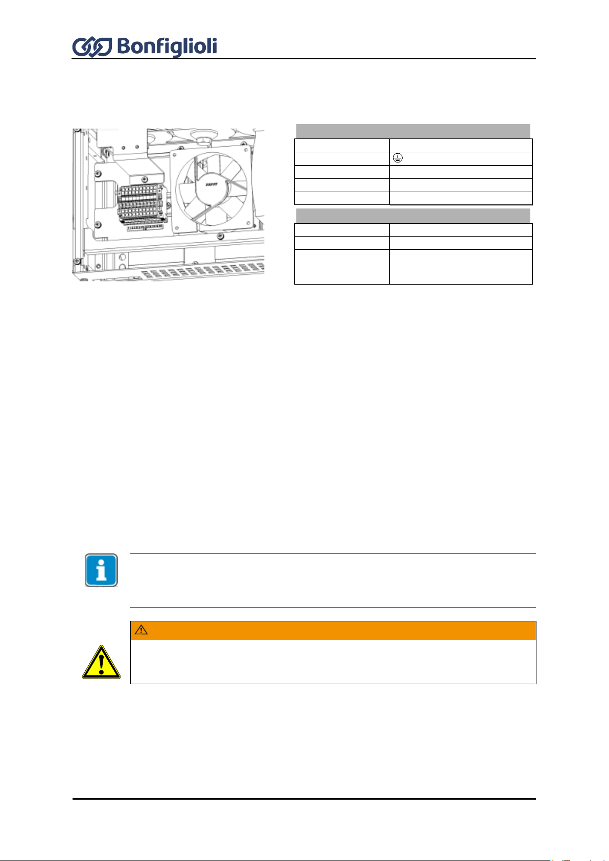
76
Operating Instructions ACU
12/16
Auxiliary voltage terminal X13
1 … 6
Not used
7
PE
8
L1 9 L2
10
L3
Connection
Connected load
≥ 1.2 kW
Supply voltage
400 V +- 10 %
Supply frequency
50 / 60 Hz
The ACU frequency inverters can evaluate the thermal switch of motor. By default, terminal X210B.1
(S6IND) is configured as an input for this evaluation. Connect the thermal switch to the digital input
and the DC 24 V supply unit X210A.1. For parameterization, refer to Sections 14.6 “Motor
temperature” and 16.4.5 “Thermocontact”.
The control hardware and the software of the frequency inverter are freely configurable to a great
extent. Certain functions can be assigned to the control terminals, and the internal logic of the
software modules can be freely selected.
Thanks to the modular design, the frequency inverter can be adapted to a great range of different
driving tasks.
The demands made of the control hardware and software are well known in the case of standard
driving tasks. This control terminal logic and internal function assignments of the software modules
are available in standard configurations. These assignments can be selected via Configuration 30.
The configurations are described in the following section.
The ACU devices of the ACTIVE Cube series feature the integrated STO function (“Safe
Torque Off”). If this function is not required, the “Controller release” signal must be
connected to inputs S1IND/STOA and S7IND/STOB.
Inputs S1IND/STOA and S7IND/STOB are connected in series.
WARNING
The digital inputs S1IND/STOA and S2IND are driven by the same signal, safe
disconnection of energy supply to the motor as per the STO safety function (“Safe
Torque OFF”) is not guaranteed.
7.7 X13 connection in ACU 501 and ACU 601
When an ACU 501 or ACU 601 device is used, connection of AC 3x400 V at X13 is required. The
illustration shows the X13 terminal on an air-cooled device as an example.
7.7.1 Motor Thermo-Contact
7.7.2 Control terminals – Wiring diagrams of configurations

12/16
Operating Instructions ACU
77
Function
V/f
Sensorless
vector
Speed
controlled
Servo
Sensorless
vector
Standard
110
410
210
510
610
Technology controller
111
411
211
511
611
Electronic gear with
position controller 1)
115
415
215
515
Electronic gear + index
controller 1)
116 216
516
Torque control
430
230
530
630
Positioning 2)
440
240
540
640
Brake control 3)
160
460
260
560
Control methods 2xx can be used with HTL encoders (with or without reference pulse)
at basic device or an extension module.
In order to use control methods 2xx with TTL encoders, an extension module is
required.
An extension module EM-RES for evaluation of resolver signals is required for operation
of a synchronous machine (control method 5xx).
An extension module EM-ABS for signal evaluation is required for operation with
absolute encoders (Hiperface, EnDat2.1, SSI).
7.8 Configurations overview
Refer to following table in order to learn which combinations of functions and control methods are
possible. Configurations „Standard“, „Technology Controller“ and „Torque Control“ will be described in
the following sections. For configurations „Electronic Gear“, „Positioning“ and „Brake Control“, please
refer to the corresponding application manuals.
Configurations:
Refer to the following manuals:
1) Application manual: Electronic Gear, Position Control and Index Control
2) Application Manual: Positioning
3) Application Manual: Hoisting Gear Drives and Load Estimation

78
Operating Instructions ACU
12/16
Control terminal X210A
X210A.1
Voltage output +20 V or input for
external power supply DC 24 V
±10%
X210A.2
GND 20 V/ GND 24 V (ext.)
X210A.3
Digital input STOA (1. shut-down
path of STO safety function)
X210A.4
Start of clockwise operation
X210A.5
Start of anticlockwise operation
X210A.6
Data Set Change-Over 1
X210A.7
Data Set Change-Over 2
Control terminal X210B
X210B.1
Motor therm. contact
X210B.2
Digital input STOA (2nd shut-down
path of STO safety function)
X210B.3
Run Signal
X210B.4
Analog signal of actual frequency
X210B.5
Supply voltage +10 V for reference
value potentiometer
X210B.6
Reference speed 0 ...+10 V
X210B.7
Ground 10 V
Control terminal X210A
X210A.1
Voltage output +20 V or input for
external power supply DC 24 V
±10%
X210A.2
GND 20 V/ GND 24 V (ext.)
X210A.3
Digital input STOA (1st shut-down
path of STO safety function)
X210A.4
Fixed Percent Change-Over 1
X210A.5
Fixed Percent Change-Over 2
X210A.6
Data Set Change-Over 1
X210A.7
Data Set Change-Over 2
Control terminal X210B
X210B.1
Motor therm. contact
X210B.2
Digital input STOB (2nd shut-down
path of STO safety function)
X210B.3
Run Signal
X210B.4
Analog signal of actual frequency
X210B.5
Supply voltage +10 V
X210B.6
Actual percentage value 0 ...+10 V
S7IND
S1OUT
MFO1A
+10 V/ 4 mA
MFI1A
GND 10 V
1
2
3
4
5
6
7
X210A
+20 V/180 mA
GND 20 V
S1IND
S2IND
S3IND
S4IND
S5IND
S6IND
X210B
1
2
3
4
5
6
7
M
V
+
+
-
STOA
STOB
24 V
ext.
S7IND
S1OUT
MFO1A
+10 V/4 mA
MFI1A
GND 10 V
1
2
3
4
5
6
7
X210A
+20 V/180 mA
GND 20 V
S1IND
S2IND
S3IND
S4IND
S5IND
S6IND
X210B
1
2
3
4
5
6
7
M
V
+
+
-
-
+
STOA
STOB
24 V
ext.
7.8.1 Configuration 110 – Sensorless Control
Configuration 110 contains the functions for variable-speed control of a 3-phase machine in a wide
range of standard applications. The motor speed is set according to the selected ratio of the reference
frequency to the necessary voltage.
7.8.2 Configuration 111 – Sensorless Control with Technology
Controller
Configuration 111 extends the functionality of the sensorless control by software functions for easier
adaptation to the customer's requirements in different applications. The Technology Controller enables
flow rate, pressure, level or speed control.

12/16
Operating Instructions ACU
79
X210B.7
Ground 10 V
Control terminal X210A
X210A.1
Voltage output +20 V or input for
external power supply DC 24 V
±10%
X210A.2
GND 20 V/ GND 24 V (ext.)
X210A.3
Digital input STOA (1st shut-down
path of STO safety function)
X210A.4
Start of clockwise operation
X210A.5
Start of anticlockwise operation
X210A.6
Data Set Change-Over 1
X210A.7
Data Set Change-Over 2
Control terminal X210B
X210B.1
Motor therm. contact
X210B.2
Digital input STOB (2nd shut-down
path of STO safety function)
X210B.3
Run Signal
X210B.4
Analog signal of actual frequency
X210B.5
Supply voltage +10 V for reference
value potentiometer
X210B.6
Reference speed 0 ...+10 V
X210B.7
Ground 10 V
Control terminal X210A
X210A.1
Voltage output +20 V or input for
external power supply DC 24 V
±10%
X210A.2
GND 20 V/ GND 24 V (ext.)
X210A.3
Digital input STOA (1st shut-down
path of STO safety function)
X210A.4
Fixed Percent Change-Over 1
X210A.5
no function assigned
X210A.6
Data Set Change-Over 1
X210A.7
Data Set Change-Over 2
Control terminal X210B
X210B.1
Motor therm. contact
X210B.2
Digital input STOB (2nd shut-down
path of STO safety function)
X210B.3
Run Signal
S7IND
S1OUT
MFO1A
+10 V/4 mA
MFI1A
GND 10 V
1
2
3
4
5
6
7
X210A
+20 V/180 mA
GND 20 V
S1IND
S2IND
S3IND
S4IND
S5IND
S6IND
X210B
1
2
3
4
5
6
7
M
V
+
+
-
STOA
STOB
24 V
ext.
S7IND
S1OUT
MFO1A
+10 V/4 mA
MFI1A
GND 10 V
1
2
3
4
5
6
7
X210A
+20 V/180 mA
GND 20 V
S1IND
S2IND
S3IND
S4IND
S5IND
S6IND
X210B
1
2
3
4
5
6
7
M
V
+
+
-
-
+
STOA
STOB
24 V
ext.
7.8.3 Configuration 410 – Sensorless Field-Oriented
Control
Configuration 410 contains the functions for sensorless, field-oriented control of an asynchronous
machine. The current motor speed is determined from the present currents and voltages in
combination with the machine parameters. Separate control of torque and flux-forming current
enables a high drive dynamism at a high load moment.
7.8.4 Configuration 411 –Sensorless Field-Oriented Control with
Technology Controller
Configuration 411 extends the functionality of the sensorless field-oriented control of Configuration
410 by a Technology Controller. The Technology Controller enables a control based on parameters
such as flow rate, pressure, filling level or speed.

80
Operating Instructions ACU
12/16
X210B.4
Analog signal of actual frequency
X210B.5
Supply voltage +10 V
X210B.6
Actual percentage value 0 ...+10 V
X210B.7
Ground 10 V
Control terminal X210A
X210A.1
Voltage output +20 V or input for
external power supply DC 24 V
±10%
X210A.2
GND 20 V/ GND 24 V (ext.)
X210A.3
Digital input STOA (1st shut-down
path of STO safety function)
X210A.4
Start of clockwise operation
X210A.5
n-/M change-over control function
X210A.6
Data Set Change-Over 1
X210A.7
Data Set Change-Over 2
Control terminal X210B
X210B.1
Motor therm. contact
X210B.2
Digital input STOB (2nd shut-down
path of STO safety function)
X210B.3
Run Signal
X210B.4
Analog signal of actual frequency
X210B.5
Supply voltage +10 V for reference
value potentiometer
X210B.6
Reference speed 0...+10 V or
reference torque as percentage
X210B.7
Ground 10 V
S7IND
S1OUT
MFO1A
+10 V/ 4 mA
MFI1A
GND 10 V
1
2
3
4
5
6
7
X210A
+20 V/180 mA
GND 20 V
S1IND
S2IND
S3IND
S4IND
S5IND
S6IND
X210B
1
2
3
4
5
6
7
M
V
+
+
-
STOA
STOB
24 V
ext.
7.8.5 Configuration 430 – Sensorless Field-Oriented Control, speed and
torque controlled
Configuration 430 extends the functionality of the sensorless field-oriented control of Configuration
410 by a Torque Controller. The reference torque is represented as a percentage and it is transmitted
into the corresponding operational performance of the application. Change-over between variablespeed control and torque-dependent control is done jerk-free during operation.
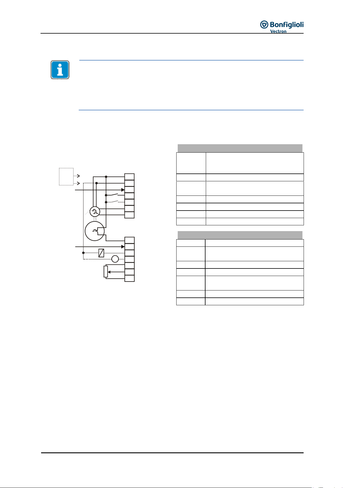
12/16
Operating Instructions ACU
81
Control methods 2xx can be used with HTL encoders (with or without reference pulse)
at basic device or an extension module.
In order to use control methods 2xx with TTL encoders, an extension module is
required.
An extension module EM-ABS for signal evaluation is required for operation with
absolute encoders (Hiperface, EnDat2.1, SSI).
Control terminal X210A
X210A.1
Voltage output +20 V or input for
external power supply DC 24 V
±10%
X210A.2
GND 20 V/ GND 24 V (ext.)
X210A.3
Digital input STOA (1st shut-down
path of STO safety function)
X210A.4
Start of clockwise operation
X210A.5
Start of anticlockwise operation
X210A.6
Speed sensor track B
X210A.7
Speed sensor track A
Control terminal X210B
X210B.1
Motor therm. contact
X210B.2
Digital input STOB (2nd shut-down
path of STO safety function)
X210B.3
Run Signal
X210B.4
Analog signal of actual frequency
X210B.5
Supply voltage +10 V for reference
value potentiometer
X210B.6
Reference speed 0 ...+10V
X210B.7
Ground 10 V
S7IND
S1OUT
MFO1A
+10 V/4 mA
MFI1A
GND 10 V
1
2
3
4
5
6
7
X210A
+20 V/180 mA
GND 20 V
S1IND
S2IND
S3IND
S4IND
S5IND
S6IND
X210B
1
2
3
4
5
6
7
M
V
+
+
-
A
B
+
-
STOA
STOB
24 V
ext.
7.8.6 Configuration 210 – Field-Oriented Control, Speed Controlled
Configuration 210 contains the functions for speed-controlled, field-oriented control of a 3-phase
machine with speed sensor feedback. The separate control of torque and flux-forming current enables
high drive dynamism with a high load moment. The necessary speed sensor feedback results in a
precise speed and torque performance.

82
Operating Instructions ACU
12/16
Control terminal X210A
X210A.1
Voltage output +20 V or input for
external power supply DC 24 V
±10%
X210A.2
GND 20 V/ GND 24 V (ext.)
X210A.3
Digital input STOA (1st shut-down
path of STO safety function)
X210A.4
Fixed Percent Change-Over 1
X210A.5
no function assigned
X210A.6
Speed sensor track B
X210A.7
Speed sensor track A
Control terminal X210B
X210B.1
Motor therm. contact
X210B.2
Digital input STOB (2nd shut-down
path of STO safety function)
X210B.3
Run Signal
X210B.4
Analog signal of actual frequency
X210B.5
Supply voltage +10 V
X210B.6
Actual percentage value 0 ...+10 V
X210B.7
Ground 10 V
Control terminal X210A
X210A.1
Voltage output +20 V or input for
external power supply DC 24 V
±10%
X210A.2
GND 20 V/ GND 24 V (ext.)
X210A.3
Digital input STOA (1st shut-down
path of STO safety function)
X210A.4
Start of clockwise operation
X210A.5
n-/M change-over control function
X210A.6
Speed sensor track B
X210A.7
Speed sensor track A
Control terminal X210B
X210B.1
Motor therm. contact
X210B.2
Digital input STOB (2nd shut-down
path of STO safety function)
X210B.3
Run Signal
X210B.4
Analog signal of actual frequency
X210B.5
Supply voltage +10 V for reference
value potentiometer
-
+
S7IND
S1OUT
MFO1A
+10 V/4 mA
MFI1A
GND 10 V
1
2
3
4
5
6
7
X210A
+20 V/180 mA
GND 20 V
S1IND
S2IND
S3IND
S4IND
S5IND
S6IND
X210B
1
2
3
4
5
6
7
M
V
+
+
-
A
B
+
-
STOA
STOB
24 V
ext.
S7IND
S1OUT
MFO1A
+10 V/4 mA
MFI1A
GND 10 V
1
2
3
4
5
6
7
X210A
+20 V/180 mA
GND 20 V
S1IND
S2IND
S3IND
S4IND
S5IND
S6IND
X210B
1
2
3
4
5
6
7
M
V
+
+
-
A
B
+
-
STOA
STOB
24 V
ext.
7.8.7 Configuration 211 – Field-Oriented Control with Technology
Controller
Configuration 211 extends the functionality of the speed-controlled, field-oriented control of
Configuration 210 by a Technology Controller. The Technology Controller enables a control based on
parameters such as flow rate, pressure, filling level or speed.
7.8.8 Configuration 230 – Field-Oriented Control, Speed and Torque
Controlled
Configuration 230 extends the functionality of Configuration 210 by functions for torque-dependent,
field-oriented control. The reference torque is represented as a percentage and it is transmitted into
the corresponding operational performance of the application. Change-over between variable-speed
control and torque-dependent control is done jerk-free during operation.

12/16
Operating Instructions ACU
83
X210B.6
Reference speed 0...+10 V or
reference torque as percentage
X210B.7
Ground 10 V
An extension module EM-RES for evaluation of resolver signals is required for operation
of a synchronous machine (control method 5xx).
An extension module EM-ABS for signal evaluation is required for operation with
absolute encoders (Hiperface, EnDat2.1, SSI).
For connection of the resolver or absolute encoder, also refer to operating instructions
of extension module.
Control terminal X210A
X210A.1
Voltage output +20 V or input for
external power supply DC 24 V
±10%
X210A.2
GND 20 V/ GND 24 V (ext.)
X210A.3
Digital input STOA (1st shut-down
path of STO safety function)
X210A.4
Start of clockwise operation
X210A.5
Start of anticlockwise operation
X210A.6
Data Set Change-Over 1
X210A.7
Data Set Change-Over 2
Control terminal X210B
X210B.1
Motor therm. contact
X210B.2
Digital input STOB (2nd shut-down
path of STO safety function)
X210B.3
Run Signal
X210B.4
Analog signal of actual frequency
X210B.5
Supply voltage +10 V for reference
value potentiometer
X210B.6
Reference speed 0 ...+10V
X210B.7
Ground 10 V
S7IND
S1OUT
MFO1A
+10 V/4 mA
MFI1A
GND 10 V
1
2
3
4
5
6
7
X210A
+20 V/180 mA
GND 20 V
S1IND
S2IND
S3IND
S4IND
S5IND
S6IND
X210B
1
2
3
4
5
6
7
M
V
+
+
-
STOA
STOB
24 V
ext.
7.8.9 Configuration 510 – Field-Oriented Control of Synchronous
Machine, Speed Controlled
Configuration 510 contains the functions for speed-controlled, field-oriented control of a synchronous
machine with resolver feedback. The separate control of torque and flux-forming current enables high
drive dynamism with a high load moment. The necessary resolver feedback results in a precise speed
and torque performance.
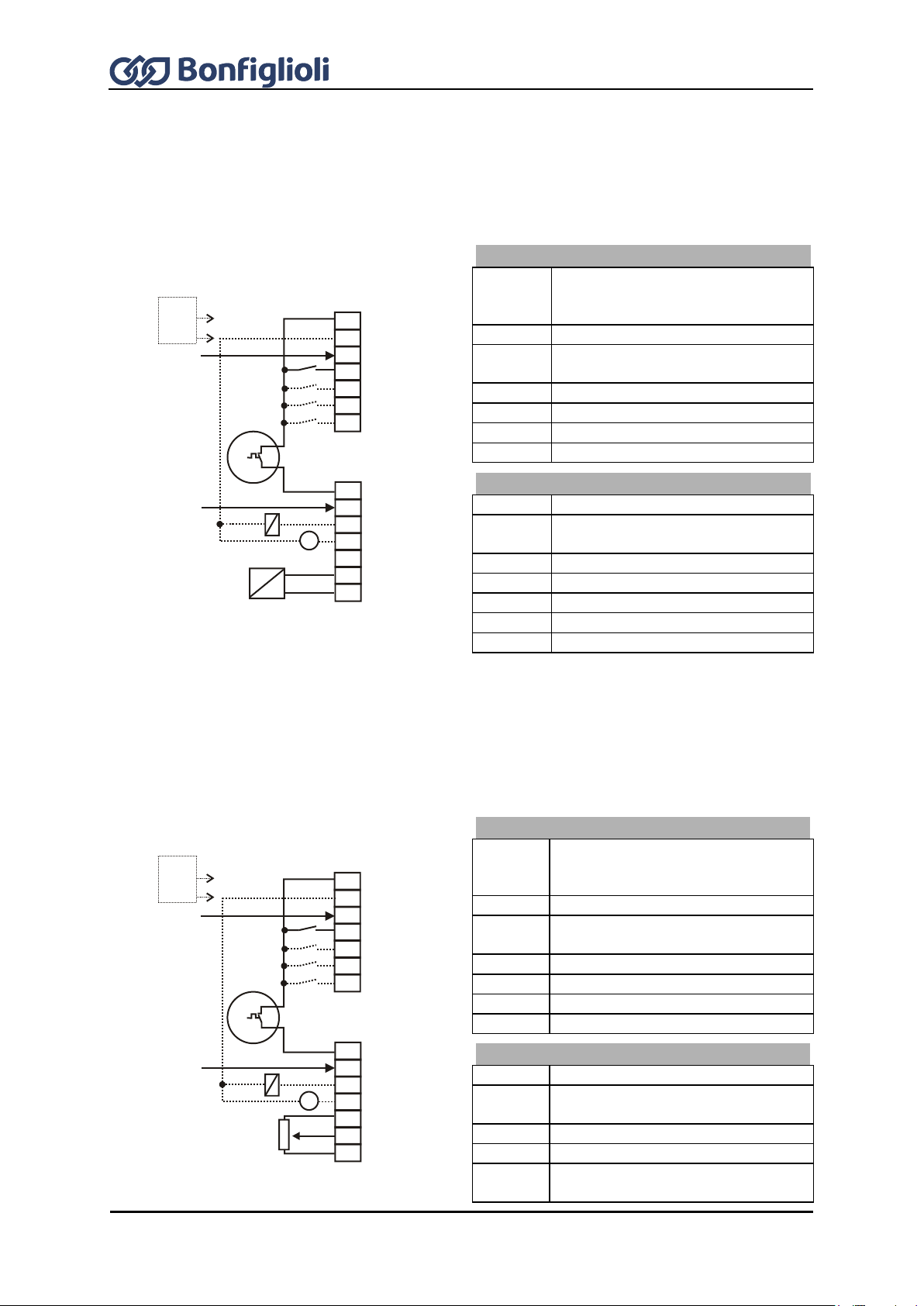
84
Operating Instructions ACU
12/16
Control terminal X210A
X210A.1
Voltage output +20 V or input for
external power supply DC 24 V
±10%
X210A.2
GND 20 V/ GND 24 V (ext.)
X210A.3
Digital input STOA (1st shut-down
path of STO safety function)
X210A.4
Fixed Percent Change-Over 1
X210A.5
no function assigned
X210A.6
Data Set Change-Over 1
X210A.7
Data Set Change-Over 2
Control terminal X210B
X210B.1
Motor therm. contact
X210B.2
Digital input STOB (2nd shut-down
path of STO safety function)
X210B.3
Run Signal
X210B.4
Analog signal of actual frequency
X210B.5
Supply voltage +10 V
X210B.6
Actual percentage value 0 ...+10 V
X210B.7
Ground 10 V
Control terminal X210A
X210A.1
Voltage output +20 V or input for
external power supply DC 24 V
±10%
X210A.2
GND 20 V/ GND 24 V (ext.)
X210A.3
Digital input STOA (1st shut-down
path of STO safety function)
X210A.4
Start of clockwise operation
X210A.5
n-/M change-over control function
X210A.6
Data Set Change-Over 1
X210A.7
Data Set Change-Over 2
Control terminal X210B
X210B.1
Motor therm. contact
X210B.2
Digital input STOB (2nd shut-down
path of STO safety function)
X210B.3
Run Signal
X210B.4
Analog signal of actual frequency
X210B.5
Supply voltage +10 V for reference
value potentiometer
S7IND
S1OUT
MFO1A
+10 V/4 mA
MFI1A
GND 10 V
1
2
3
4
5
6
7
X210A
+20 V/180 mA
GND 20 V
S1IND
S2IND
S3IND
S4IND
S5IND
S6IND
X210B
1
2
3
4
5
6
7
M
V
+
+
-
-
+
STOA
STOB
24 V
ext.
S7IND
S1OUT
MFO1A
+10 V/4 mA
MFI1A
GND 10 V
1
2
3
4
5
6
7
X210A
+20 V/180 mA
GND 20 V
S1IND
S2IND
S3IND
S4IND
S5IND
S6IND
X210B
1
2
3
4
5
6
7
M
V
+
+
-
STOA
STOB
24 V
ext.
7.8.10 Configuration 511 –Field-Oriented Control of Synchronous
Machine with Technology Controller
Configuration 511 extends the functionality of the field-oriented control of a synchronous machine of
Configuration 510 by a Technology Controller. The Technology Controller enables a control based on
parameters such as flow rate, pressure, filling level or speed.
7.8.11 Configuration 530 – Field-Oriented Control of a Synchronous
Machine Speed and Torque Controlled
Configuration 530 extends the functionality of Configuration 510 by functions for torque-dependent,
field-oriented control. The reference torque is represented as a percentage and it is transmitted into
the corresponding operational performance of the application. Change-over between variable-speed
control and torque-dependent control is done jerk-free during operation.

12/16
Operating Instructions ACU
85
X210B.6
Reference speed 0...+10 V or
reference torque as percentage
X210B.7
Ground 10 V
Control terminal X210A
X210A.1
Voltage output +20 V or input for
external power supply DC 24 V
±10%
X210A.2
GND 20 V/ GND 24 V (ext.)
X210A.3
Digital input STOA (1st shut-down
path of STO safety function)
X210A.4
Start of clockwise operation
X210A.5
Start of anticlockwise operation
X210A.6
Data Set Change-Over 1
X210A.7
Data Set Change-Over 2
Control terminal X210B
X210B.1
Motor therm. contact
X210B.2
Digital input STOB (2nd shut-down
path of STO safety function)
X210B.3
Run Signal
X210B.4
Analog signal of actual frequency
X210B.5
Supply voltage +10 V for reference
value potentiometer
X210B.6
Reference speed 0 ...+10 V
X210B.7
Ground 10 V
Control terminal X210A
X210A.1
Voltage output +20 V or input for
external power supply DC 24 V
±10%
X210A.2
GND 20 V/ GND 24 V (ext.)
X210A.3
Digital input STOA (1st shut-down
path of STO safety function)
X210A.4
Fixed Percent Change-Over 1
X210A.5
no function assigned
X210A.6
Data Set Change-Over 1
X210A.7
Data Set Change-Over 2
Control terminal X210B
X210B.1
Motor therm. contact
S7IND
S1OUT
MFO1A
+10 V/4 mA
MFI1A
GND 10 V
1
2
3
4
5
6
7
X210A
+20 V/180 mA
GND 20 V
S1IND
S2IND
S3IND
S4IND
S5IND
S6IND
X210B
1
2
3
4
5
6
7
M
V
+
+
-
STOA
STOB
24 V
ext.
S7IND
S1OUT
MFO1A
+10 V/4 mA
1
2
3
4
5
6
7
X210A
+20 V/180 mA
GND 20 V
S1IND
S2IND
S3IND
S4IND
S5IND
S6IND
X210B
1
2
3
4
M
V
+
+
-
STOA
STOB
24 V
ext.
7.8.12 Configuration 610 – Sensorless Field-Oriented Control of
Synchronous Machine, Speed Controlled
Configuration 610 contains the functions for sensorless field-oriented control of a synchronous
machine with resolver feedback. The separate control of torque and flux-forming current enables high
drive dynamism with a high load moment. The missing resolver feedback results in slightly lower
dynamism and speed quality compared to Configuration 510.
7.8.13 Configuration 611 – Sensorless Field-Oriented Control of
Synchronous Machine with Technology Controller
Configuration 611 extends the functionality of the sensorless field-oriented control of a synchronous
machine of Configuration 610 by a Technology Controller. The Technology Controller enables a control
based on parameters such as flow rate, pressure, filling level or speed.

86
Operating Instructions ACU
12/16
X210B.2
Digital input STOB (2nd shut-down
path of STO safety function)
X210B.3
Run Signal
X210B.4
Analog signal of actual frequency
X210B.5
Supply voltage +10 V
X210B.6
Actual percentage value 0 ...+10 V
X210B.7
Ground 10 V
Control terminal X210A
X210A.1
Voltage output +20 V or input for
external power supply DC 24 V
±10%
X210A.2
GND 20 V/ GND 24 V (ext.)
X210A.3
Digital input STOA (1st shut-down
path of STO safety function)
X210A.4
Start of clockwise operation
X210A.5
n-/M change-over control function
X210A.6
Data Set Change-Over 1
X210A.7
Data Set Change-Over 2
Control terminal X210B
X210B.1
Motor therm. contact
X210B.2
Digital input STOB (2nd shut-down
path of STO safety function)
X210B.3
Run Signal
X210B.4
Analog signal of actual frequency
X210B.5
Supply voltage +10 V for reference
value potentiometer
X210B.6
Reference speed 0...+10 V or
reference torque as percentage
X210B.7
Ground 10 V
S7IND
S1OUT
MFO1A
+10 V/ 4 mA
MFI1A
GND 10 V
1
2
3
4
5
6
7
X210A
+20 V/180 mA
GND 20 V
S1IND
S2IND
S3IND
S4IND
S5IND
S6IND
X210B
1
2
3
4
5
6
7
M
V
+
+
-
STOA
STOB
24 V
ext.
7.8.14 Configuration 630 – Sensorless Field-Oriented Control of a
Synchronous Machine Speed and Torque Controlled
Configuration 630 extends the functionality of the sensorless field-oriented control of Configuration
610 by a Torque Controller. The reference torque is represented as a percentage and it is transmitted
into the corresponding operational performance of the application. Change-over between variablespeed control and torque-dependent control is done jerk-free during operation.
7.9 Notes on installation as per UL508c
Thermal motor protection as per UL508c can be realized in devices marked with “TM included” under
the nameplate. For ACU devices without the “TM included” label, the following applies as per UL508c:
Motor overtemperature identification not featured by the device.
For connection and parameterization of the thermal motor evaluation, refer to Chapter 14.6 "Motor
temperature", 16.4.5 "Thermocontact" and 19.5 "Motor circuit breaker".
For installation as per UL508c, the mains feeder may only be protected using approved fuses. For
approved fuses, refer to Chapter 5 "Technical data".
For installation as per UL508c, the maximum temperatures specified in Chapter 5 "Technical data"
must not be exceeded.
For installation as per UL508c, only copper cables with a rated current of 60/75°C may be used.
For installation as per UL508c, the devices may only be used in "Pollution Degree 2" environments.
According to UL508c, warnings and markings/labels must not be removed.

12/16
Operating Instructions ACU
87
A
B
C
D
E
F
G
H
I
J
Buttons
A
RUN
Used for starting the drive and opening the CTRL menu.
Press the RUN key to open the motor potentiometer function.
STOP
Used for opening the CTRL menu, stopping the drive and acknowledging faults
J
▲ ▼
Navigate in menu structure and select parameters.
Increase or reduce parameter values.
ENT
Open parameters or switch within the menu structure.
Confirm the selected function or parameter.
ESC
Used for aborting parameters or switching back to the previous menu within the menu
structure. Cancel the function or reset parameter value.
FUN
Used for switching over the key function, access to special functions.
Display
B
Three-digit 7-segment display to show the parameter number.
C
One-digit 7-segment display for display of the active data record, direction of rotation etc.
D
Display selected menu branch:
VAL
Show actual values.
PARA
Select parameters and adjust parameter values.
CTRL
Select a function for adjustment and/or display via the operating unit:
SEtUP Guided commissioning.
CtrL motor potentiometer and jog function.
CPY
Copy parameters via the control unit:
ALL All parameter values are copied.
Act Active parameter values are copied only.
FOr Control unit memory is formatted and deleted.
E
Status and operating messages:
WARN
Warning about a critical operating behavior.
FAULT
Message indicating that the unit was switched off due to a fault.
RUN
Flashing: signalizes readiness for operation
Lighting signalizes operation and release of the power part
REM
Active remote control via interface connection.
F Function switch-over with the FUN key.
F
Five-digit 7-segment display for display of parameter value and sign.
G
Physical unit of parameter value displayed.
H
Active acceleration or deceleration ramp.
I
Current direction of rotation of the drive.
8 Control unit KP500
The optional KP500 control unit is a practical tool for controlling the frequency inverter and setting
and displaying the frequency inverter parameters.
The control unit is not absolutely necessary for the operation of the frequency inverter and can be
plugged on when required.

88
Operating Instructions ACU
12/16
NOTICE
In the following description of the key functions, a plus (+) between the key symbols
indicates that the keys have to be pressed at the same time.
A comma (,) between the key symbols indicates that the keys have to be pressed one
after the other.
Menu branch – VAL
Display of actual values
Menu branch – PARA
Display and edit parameters
Menu branch – CPY
Copy parameters
Menu branch – CTRL
Select control and test functions
Buttons
▲ ▼
Navigate through the menu structure and select a menu branch
ENT
Open the selected menu branch
ESC
Quitting the menu branch and return to the main menu.
8.1 Menu structure
The menu structure of the control unit is arranged as shown in the following illustration. Use the
arrow keys as well as ESC and ENT to navigate through the menu. The software contains the full set
of information and enables a flexible use of the parameter setting and control options.
8.2 Main Menu
The various parameters and information of the frequency inverter can be displayed by means of the
control unit. The different functions and parameters are grouped together in four menu branches.
From any point in the menu structure you can return to the main menu by pressing the ESC key either
continuously or repeatedly.
Use the arrow keys to select the required menu branch. The selected menu branch is displayed
(flashing).
Select the menu branch by pressing the ENT key. The first parameter or the first function in the
selected menu branch will be displayed.
If you press the ESC key you will return to the main menu of the control unit.

12/16
Operating Instructions ACU
89
In the VAL menu branch, the control unit displays a variety of actual values, depending on the
configuration selected and the options installed. The parameters and basic software functions linked
to the corresponding actual value are documented in the operating instructions.
ENT
ESC
ENT
ESC
A
B
C
D
E
A
Use the arrow keys to select the required number from the actual values displayed in
numerical order.
When you have reached the highest parameter number, the smallest parameter number is
displayed once you press the ▲ button.
When you have reached the smallest parameter number, the highest parameter number is
displayed once you press the ▼.
In the current data set, the data set related actual value parameters are displayed, including
the corresponding data set number. The seven-segment display shows data record 0 if the
actual values in the four data sets are identical.
Buttons
▲ + ▼
Display the actual value parameter upon startup.
FUN , ▲
Display last actual value parameter (highest number).
FUN , ▼
Display first actual value parameter (lowest number).
B
Use the ENT key to select the actual value. The parameter is displayed including its current
value, unit and the active data set.
C
During commissioning, operation and error analysis, it is possible to monitor each actual value
parameter specifically.
Some of the actual value parameters are arranged in the four available data sets. If the
parameter values in the four data records are identical, the actual value is displayed in data
record 0. If the actual values in the four data set are different, diFF is displayed in data set 0.
Buttons
▲ , ▼
Switch to another of the data set in the case of related actual values.
FUN , ▲
Determine minimum value and display it permanently.
FUN , ▼
Determine and display minimum actual value permanently.
FUN , ENT
Display of mean value of the actual value during the
monitoring period.
D
Use the ENT key to save the selected actual value as a parameter displayed at switch-on. The
message SEt (with parameter number) is displayed for a short time. When the frequency
inverter is switched on the next time, this actual value will be displayed automatically.
E
After saving the parameter, you can monitor and display the value again. Use the ESC key to
switch to the parameter selection of the VAL menu branch.
8.3 Actual Value Menu (VAL)

90
Operating Instructions ACU
12/16
The parameters to be configured during the guided commissioning procedure were selected from
common applications and can be supplemented as required by further settings in the PARA menu
branch. The parameters and basic software functions linked to the corresponding actual value are
documented in the operating instructions.
A
Use the arrow keys to select the required number from the parameters displayed in numerical
order. The parameter number is displayed with the active data set (flashes).
When you have reached the highest parameter number, the smallest parameter number is
displayed once you press the ▲ button.
When you have reached the smallest parameter number, the highest parameter number is
displayed once you press the ▼.
In the case of parameter numbers > 999, the first digit will be displayed in hexadecimal form
(999, A00 … B5 … C66).
In the current data set, the related parameters are displayed, including the corresponding data
set number. The seven-segment display shows data set 0 if the parameter values in the four
data sets are identical.
Buttons
▲ + ▼
Change to the last parameter edited.
FUN , ▲
Display of last parameter (highest number).
FUN , ▼
Display of first parameter (lowest number).
B
Use the ENT key to select the parameter. The parameter is displayed including its value, unit
and the active data set. If settings are edited in data set 0, the parameter values are changed
in the four data sets.
C
Use the arrow keys to adjust the parameter value or to select an operation mode. The
adjustment possibilities you have depend on the parameter.
Keep the arrow keys pressed for a while to change the displayed values quickly. If you release
the keys again, the speed at which the values change is reduced again.
If the parameter value starts to flash, the speed at which the values change is reset to the
initial value again.
Buttons
▲ + ▼
Set parameter to factory setting.
FUN , ▲
Set parameter to highest value.
FUN , ▼
Set parameter to smallest value.
FUN , ENT
Change of the data set in the case of data set related parameters.
D
Use the ENT key to save the parameter. For a short time, the message SEt including the
parameter number and the data set is displayed. To leave the parameter unchanged, press the
ESC key.
Messages
Err1: EEPrO
Parameter has not been saved.
Err2: StOP
Parameter can only be read (i.e. not edited) when the unit is in operation.
Err3: Error
Other error.
E
After saving the parameter, you can edit the value again or return to the parameter selection
menu by pressing the ESC key.
ENT
ENT
ESC
A
B
C
D
E
8.4 Parameter Menu (PARA)
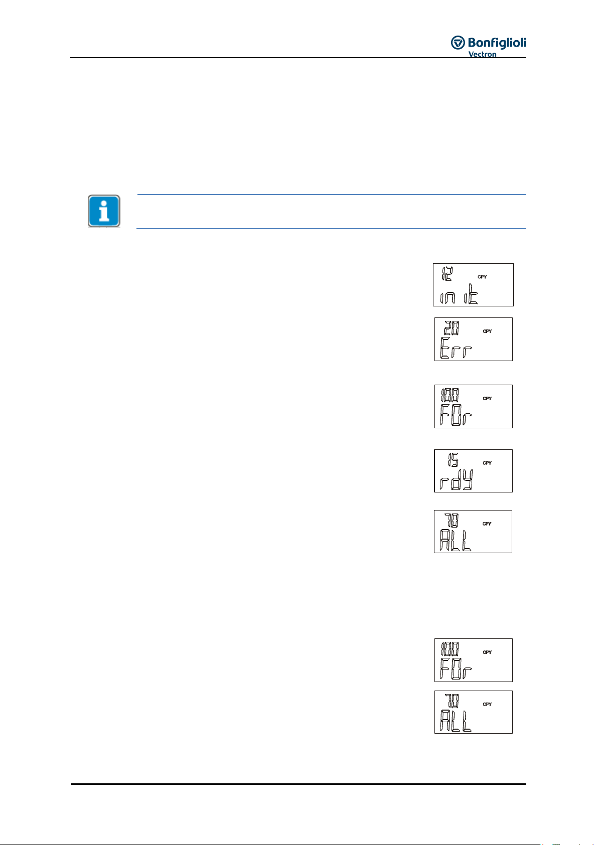
12/16
Operating Instructions ACU
91
The Copy Menu (CPY) is accessible in control level 3. The control level can be adjusted,
if necessary, via parameter Control Level 28.
When you open the CPY menu branch, the data stored in the control unit are
read out. This process takes a few seconds. During this time, init and a
progress indicator will be displayed. After the initialization in the copy menu,
the function can be selected.
If the information stored in the control unit is not valid, the initialization is
stopped and an error message is displayed.
In this case, the memory in the control unit must be formatted as follows:
Use the ENT key to confirm the error message.
Use the arrow keys to select the function FOr.
Use the ENT key to confirm the selection.
During the formatting process, FCOPY and a progress indicator are
displayed.
The process takes a few seconds. When the process is complete, the
message rdY is displayed.
Confirm the message by pressing the ENT key.
Now, you can select the copy function as described in the following.
Function – FOr
Use the function For to format and delete the memory in the control unit.
This may be necessary if a new control unit is used for the first time.
Function – ALL
All readable and writable parameter values are transferred.
Confirm this selection by pressing the ENT key and continue by selecting
the source.
8.5 Copy Menu (CPY)
With the copy function of the control unit you can copy parameter values from the frequency inverter
to a non-volatile memory of the control unit (upload) and store (download) them to a frequency
inverter again.
The copy function makes the parameterization of recurring applications much easier. The function
archives all parameter values, regardless of access control and value range. The memory space
available in the control unit for the files is dynamically scaled to match the scope of the data.
8.5.1 Reading the Stored Information
8.5.2 Menu structure
The copy menu CPY contains three main functions. Use the arrow keys to select the required function.
Select the source and the destination for the process. The memory space available in the non-volatile
memory of the control unit is displayed as a percentage on the three-digit seven-segment display.
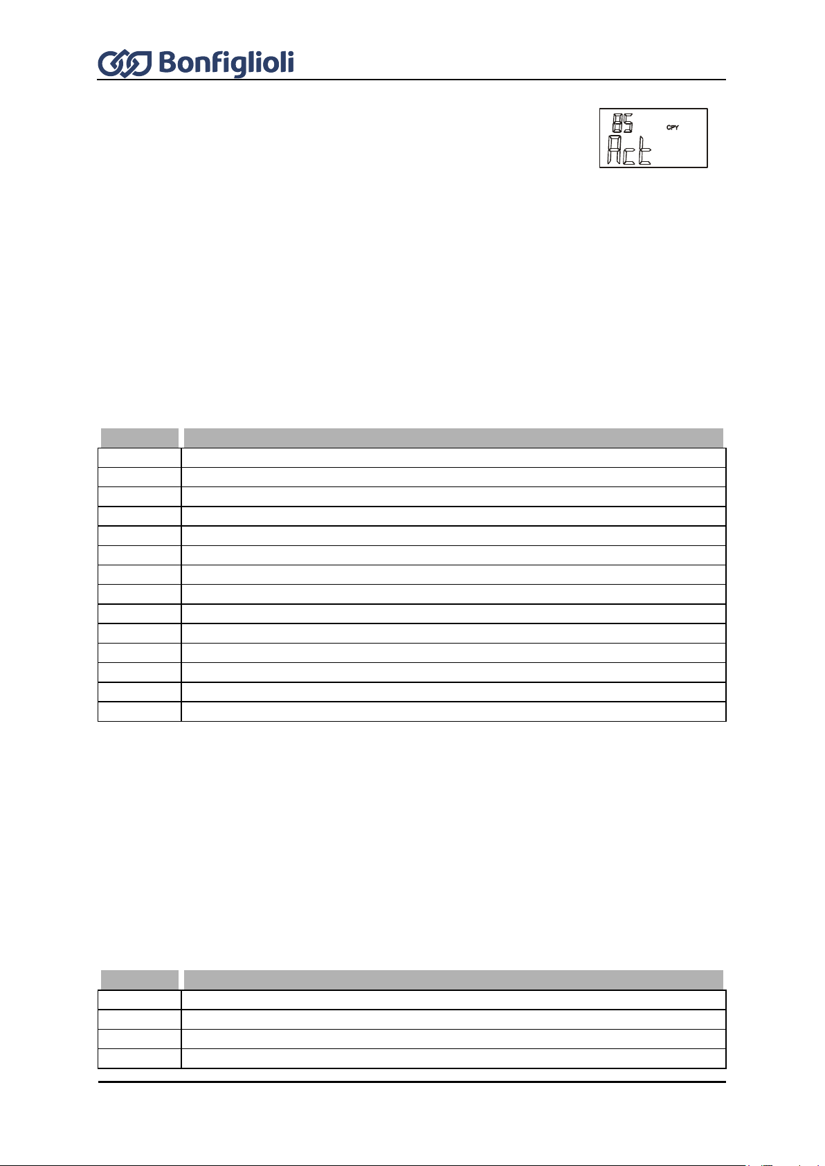
92
Operating Instructions ACU
12/16
Function – Act
The active parameter values of the frequency inverter are copied to the
control unit only. The number of active parameter values depends in the
current or selected configuration of the frequency inverter.
When copying the data from the control unit to the frequency inverter, all
stored parameter values are transmitted, like in the case of the ALL function.
For the copy operation, confirm the selection Act by pressing the ENT
button and selecting the source.
The parameters of the ALL and Act sub-function in the CPY menu branch can be parameterized to
meet the requirements of the specific application. The available memory space of the control unit is
shown on the seven-segment display.
Use the arrow keys to select the data source (Src.) for the copy operation (upload). The data
sets of the frequency inverter (Src. x) or the files of the control unit (Src. Fy) can be used as the
data source.
Confirm the data source selected by pressing the ENT key and continue by selecting the target.
Display
Description
Src.
0
The data of the four data sets of the frequency inverter are copied.
Src.
1
The data of data set 1 of the frequency inverter are copied.
Src.
2
The data of data set 2 of the frequency inverter are copied.
Src.
3
The data of data set 3 of the frequency inverter are copied.
Src.
4
The data of data set 4 of the frequency inverter are copied.
Src.
E
An empty data set for deletion of a file in the control unit.
Src.
F1
File 1 is transferred from the memory of the control unit. 1)
Src.
F2
File 2 is transferred from the memory of the control unit. 1)
Src.
F3
File 3 is transferred from the memory of the control unit. 1)
Src.
F4
File 4 is transferred from the memory of the control unit. 1)
Src.
F5
File 5 is transferred from the memory of the control unit. 1)
Src.
F6
File 6 is transferred from the memory of the control unit. 1)
Src.
F7
File 7 is transferred from the memory of the control unit. 1)
Src.
F8
File 8 is transferred from the memory of the control unit. 1)
1)
Empty files not yet filled with data will not be offered as signal source. The memory of the control unit is
managed dynamically (Chapter 8.5 "Copy Menu (CPY)").
Select the destination (dSt.) of the copy operation (application-specific). The data source is
transferred to the selected target (download).
Use the arrow keys to select the destination (dSt.) of the copied data (download). Depending on
the data source selected, either the data sets of the frequency inverter (dSt. x) or still empty
files of the control unit (dSt. F y) are available as the target.
Confirm your selection by pressing the ENT key. The copy operation will start and COPY will be
displayed.
Display
Description
dSt.
0
The four data sets of the frequency inverter are overwritten.
dSt.
1
The data are copied to data set 1 of the frequency inverter.
dSt.
2
The data are copied to data set 2 of the frequency inverter.
dSt.
3
The data are copied to data set 3 of the frequency inverter.
8.5.3 Selecting the Source
8.5.4 Selecting the Destination

12/16
Operating Instructions ACU
93
Display
Description
dSt.
4
The data are copied to data set 4 of the frequency inverter.
dSt.
F1
The data are copied to file 1 of the control unit. 1)
dSt.
F2
The data are copied to file 2 of the control unit. 1)
dSt.
F3
The data are copied to file 3 of the control unit. 1)
dSt.
F4
The data are copied to file 4 of the control unit. 1)
dSt.
F5
The data are copied to file 5 of the control unit. 1)
dSt.
F6
The data are copied to file 6 of the control unit. 1)
dSt.
F7
The data are copied to file 7 of the control unit. 1)
dSt.
F8
The data are copied to file 8 of the control unit. 1)
1)
Already existing files will not be offered as copy target.
Before the parameter settings are transferred to the frequency inverter, the individual
parameter values are checked.
The value range and the parameter settings can differ according to the power range of
the frequency inverter. Parameter values which are outside of the value range will
trigger a copy error message. In case a device error is triggered as a result of copying,
the device error will only be displayed once the copying has been completed.
While the copy operation is in process, the message COPY and, as a
progress indicator, the number of the currently copied parameter will be
displayed
In the case of the Act function, the active parameter values are copied only.
Using the ALL function, parameters which are not relevant to the selected
configuration are copied, too.
Depending on the configuration selected (ALL or Act), the copy operation will
be completed after approx. 100 seconds and the message rdY will be
displayed.
Press the ENT key to switch to the copy menu. Use the ESC key to switch to
the target selection menu.
If the ESC key is pressed during the copy operation, the copy operation is
aborted before the transmission of the data is complete. The message Abr
and the number of the last parameter which was copied are displayed.
Press the ENT key to return to the selection in the copy menu. Use the ESC
key to switch to the target selection menu.
The copy function archives all parameters, regardless of the access control
and the value range. Some of the parameters are only writable if the
frequency inverter is not in operation. The controller enable input (S1IND,
S7IND) may not be activated during the copy operation, otherwise the data
transmission is aborted. The message StO and the number of the last
parameter which was copied are displayed. If the controller enable input is
deactivated again, the aborted copy operation is continued.
The data transmission from the selected source to the destination is
continuously monitored by the copy function. If an error occurs, the copy
operation is aborted and the message Err and an error code are displayed.
8.5.5 Copy Operation
8.5.6 Error messages

94
Operating Instructions ACU
12/16
Error messages
Key
Meaning
0
1
Write error in memory of control unit; repeat the copy operation. If error message is
displayed again, format the memory.
2
Read error in memory of control unit; repeat the copy operation. If error message is
displayed again, format the memory.
3
The size of the memory of the control unit was not determined correctly.
If this error occurs repeatedly, replace the control unit.
4
Not enough memory; the data are incomplete.
Delete the incomplete file and date no longer needed from the control unit.
5
The communication has been disturbed or interrupted; repeat the copy function, delete
the incomplete file if necessary.
1
0
Invalid identification of a file in the operating unit; delete faulty file and format
memory if necessary.
2
The memory space of the selected target file is occupied; delete file or use different
target file in the operating unit.
3
The source file to be read in the control unit is empty; only files containing reasonable
data should be selected as a source.
4
Defective file in the control unit; delete defective file and format memory if necessary.
2 0 The memory in the control unit is not formatted; format the memory via the FOr
function in the copy menu.
3
0
Error during reading of a parameter from the frequency inverter; check connection
between the control unit and the frequency inverter and repeat reading operation.
1
Error during writing of a parameter in the frequency inverter;
Check connection between the control unit and the frequency inverter and repeat the
writing operation.
2
Unknown parameter type; delete faulty file and format memory if necessary.
4 0 The communication has been disturbed or interrupted; repeat the copy function, delete
the incomplete file if necessary.
„Parameter transmission“ enables the transmission of parameter values from the control unit KP 500
to the frequency inverter. In this operation mode, all other functions of the control unit are disable,
except for the COPY function. Transmission from the frequency inverter to the control unit is also
disabled.
Activation of the control unit KP 500 for parameter transfer is prepared via parameter Program 34.
The control unit KP 500 must be connected to the frequency inverter.
Program 34
Function
111 -
Parameter
transmission
Control unit P 500 is prepared for parameter transmission. A
connected frequency inverter can receive data from the control unit.
110 -
Standard operation
Resetting of control unit KP 500 to standard operation mode.
Parameter transmission mode can be activated on the control unit KP 500 only if at
least 1 file is stored in the control unit. Otherwise, the error message “F0A10” will be
displayed as soon as activation is attempted.
The control unit KP 500 can be configured both via the keys of the KP 500 and via any available CM
communication module. For configuration and activation of the KP 500 control unit, proceed as
follows:
8.6 Reading Data From Control Unit
8.6.1 Activation

12/16
Operating Instructions ACU
95
Activation via keyboard of control unit
In the parameter menu PARA, use the arrow keys to select parameter Program 34, and confirm
your selection by pressing the ENT key.
Use the arrow keys to set value 111 – Parameter transmission and confirm your selection by
pressing the ENT key.
Now the control unit is ready for activation.
Before data transmission, the control unit must be initialized:
Unplug the control unit from the frequency inverter and connect again to the same or another
frequency inverter.
The initialization is started. During the time of initialization, init and a progress indicator are
displayed. After initialization, the control unit KP°500 is ready for transfer of data to the
frequency inverter.
Adjustment of parameter Program 34 to value 111 – Parameter transmission, can be
undone via the control unit, provided that the control unit has not been initialized yet.
In Parameter Program 34 use the arrow keys to set the value
110 – Normal operation again and confirm by pressing the ENT key.
Activation of the control unit through a communication connection is possible only if
the frequency inverter is fitted with an optional communication module CM, and
communication takes place via this module. The control unit must be connected to the
frequency inverter.
The files stored in the control unit contain all information and parameters stored
according to the selected copy function ALL or Act (see Chapter 8.5 "Copy Menu
(CPY)") in the control unit.
Activation via communication module CM
Establish connection to frequency inverter.
Start communication and select parameter Program 34 via the communication interface.
Via the communication interface, enter value 111 in parameter Program 34 and confirm this
value.
Via the communication interface in parameter Program 34, enter 123 and confirm this value.
The frequency inverter is re-initialized. The display of the control unit reads rESEt. After that, the
unit is initialized.
8.6.2 Data transfer
In order to transmit a file from the control unit to the frequency inverter, proceed as follows:
Connect control unit KP 500 to the frequency inverter.
After initialization, the data sources available for transmission are displayed.
Use the arrow keys to select the data source (Src. Fy) for the transmission to the frequency
inverter.
The files stored in the control unit are available as data sources.
Confirm your selection by pressing the ENT key.
The copy process is started. While the copy operation is in process, COPY and, as a progress
indicator, the number of the currently copied parameter will be displayed.
As soon as the copy operation is complete, the control unit will be re-initialized.

96
Operating Instructions ACU
12/16
A control unit KP°500 activated for parameter transmission can be reset to full functionality
(standard operation) via a specific key code on the control unit or via each available communication
module CM.
Resetting on control unit
Press RUN and STOP keys on control unit simultaneously for approx. 1 second.
When the process is complete, – – – – – is displayed briefly. Then the top menu level of the
control unit is available.
In the parameter menu PARA, use the arrow keys to select parameter Program 34, and confirm
your selection by pressing the ENT key.
Use the arrow keys to set value 110 – Normal operation and confirm your selection by pressing
the ENT key.
The control unit is set to normal operation.
Resetting via communication module CM and/or using control software VPlus
Resetting of the control unit through a communication connection is possible only if the
frequency inverter is fitted with an optional communication module CM, and
communication takes place via this module.
Establish connection to frequency inverter.
Start communication and select parameter Program 34 via the communication connection.
Via the communication connection, enter value 110 in parameter Program 34 and confirm this
value.
Via the communication connection enter value 123 in parameter Program 34 and confirm this
value by pressing Enter.
The frequency inverter is reset. The display of the control unit reads rESEt.
After resetting, the control unit is available again with full functionality.
In order to be able to control the drive via the control unit, the digital inputs
S1IND/STOA and S7IND/STOB must be connected for enabling the output.
CAUTION
The unit may only be connected with the power supply switched off.
Verify safe isolation from power supply.
Switch off power supply before connecting or disconnecting the control inputs and
outputs. Otherwise, components may be damaged.
In the CTRL menu branch, various functions are available which make commissioning easier and
enable the control of the inverter via the control unit.
The frequency inverters can be controlled by means of the control unit and/or a communication
module.
If you want to control the frequency inverter via an optional communication module, the necessary
adjustments can be made via parameter Local/Remote 412. Via this parameter, you can specify
which functions will be available to the controller. Depending on the operation mode selected, only
some of the control menu functions are available. Refer to chapter 19.3 "Bus controller" for a
detailed description of parameter Local/Remote 412.
8.6.3 Resetting to Normal Operation
8.7 Control Menu (CTRL)

12/16
Operating Instructions ACU
97
In order to be able to control the drive via the control unit, the digital inputs
S1IND/STOA (STOA/terminal X210A.3) and S7IND/STOB (STOB/terminal X210B.2)
must be connected for enabling the output. These are the inputs for the shut-down
paths of the ST= safety function “Safe Torque Off”.
CAUTION
The unit may only be connected with the power supply switched off.
Verify safe isolation from power supply.
Switch off power supply before connecting or disconnecting the control inputs and
outputs. Otherwise, components may be damaged.
: When the RUN key was pressed, the drive was in operation already.
The CTRL menu branch can be accessed via the navigation within the menu
structure. The CtrL function contains sub-functions which are displayed
according to the operating point of the frequency inverter.
Pressing the RUN key leads to a direct change from anywhere within the menu
structure to the motorpoti function PotF for clockwise rotation or Potr for
anticlockwise rotation.
If the drive is already running, the display reads intF (forward, clockwise) / intr
(backward, anticlockwise) for the internal reference value function or inPF
(forward, clockwise) / inPr (backward, anticlockwise) for the
“Motorpoti (KP)” function.
The function „Motorpoti (KP)“ enables linking to other reference sources in the
reference frequency channel. The function is described in Chapter
15.10.2 "Motorpoti (KP)".
8.8 Controlling the Motor via the Control Unit
The operating unit enables control of the connected motor in accordance with the selected operating
mode of the parameter Local/Remote 412.

98
Operating Instructions ACU
12/16
Motor potentiometer function Pot
Using the arrow keys, you can adjust the output frequency of the frequency
inverter from the Minimum Frequency 418 to the Maximum Frequency 419.
The acceleration corresponds to the factory settings (2 Hz/s) for parameter
Ramp Keypad-Motorpoti 473. Parameters Acceleration (Clockwise) 420 and
Deceleration (Clockwise) 421 are considered in the case of low acceleration
values.
Internal reference value int
The drive is in operation, i.e. output signals are present at the frequency
inverter and the current actual value is displayed. Press an arrow key to switch
to the motor potentiometer function Pot. The current frequency value is taken
over in the motor potentiometer function Pot.
Function Motorpoti (KP) inP
Using the arrow keys, you can adjust the output frequency from Minimum
Frequency 418 to Maximum Frequency 419. The frequency value adjusted via
the control unit can be linked to other reference values via the Reference
Frequency Source 475 (Chapter 15.4 "Frequency reference channel" and
15.10.2 "Motorpoti (KP)").
JOG-Frequency JOG
This function is useful for manual setup and positioning of a machine. The
frequency of the output signal is set to the entered value if the FUN key is
pressed.
Press FUN key to switch from the internal reference value int or the motor
potentiometer function Pot to parameter JOG-Frequency 489.
While keeping the FUN key pressed, press the arrow keys to adjust the
required frequency.
(The last frequency value set will be saved in parameter JOG-Frequency
489 .)
Release the FUN key to stop the drive.
(The display returns to the previous function Pot or int. or inP if function
“Motorpoti (KP)” is activated).
Key functions
ENT
Reversal of the sense of rotation independent of the control signal on the terminals
Clockwise S2IND or Anticlockwise S3IND.
ESC
Cancel function and return to the menu structure.
FUN
Switch from internal reference value int or motor potentiometer function Pot to JOGFrequency; the drive will start.
Release the key to switch to the sub-function and stop the drive.
RUN
Start drive; alternative to control signal S2IND or S3IND.
STOP
Stop drive; alternative to control signal S2IND or S3IND.
CAUTION
If you press the ENT key, the Sense of Rotation is changed independent of the
signal on the terminals Clockwise S2IND or Anticlockwise S3IND.
If the Minimum Frequency 418 is set to 0.00 Hz, the sense of rotation of the
motor changes as soon as the sign of the reference frequency value changes.

12/16
Operating Instructions ACU
99
NOTICE
If filters (e.g. dU/dt filters or sine filters) are used between the frequency inverter and
machine, the following must be noted.
For configurations with sensor feedback (2xx, 5xx):
Carry out the installation with the filter connected. Note the filter manufacturer's
specifications concerning permissible switching frequencies. During setup note that
the filter may be overloaded thermally.
For configurations without sensor feedback (1xx, 4xx, 6xx):
Carry out the installation without connected filters. After setup, connect the filters
between the frequency inverter and the motor.
NOTICE
In liquid-cooled devices:
Vent the cooling circquit.
Initiate the cooling circuit.
See instructions in the "Operating Instructions Liquid Cooling Supplemental" document.
After completion of the installation work, make sure to check all control and power connections
again before switching on the mains voltage. When all electrical connections are correct, make sure
that the frequency inverter is not enabled (control inputs S1IND/STOA and S7IND/STOB open). After
power-up, the frequency inverter carries out a self-test and the relay output (X10) reports "Fault".
After a few seconds, the frequency inverter self-test is complete, the relay (X10) picks up and
signals "no fault ".
If the unit is in "as-delivered" condition or after resetting the unit to the factory settings, the guided
commissioning procedure is started automatically. On the control unit, the “SetUP“ menu from the
menu branch CTRL is displayed.
The guided commissioning of the frequency inverter determines all parameter settings relevant to
the required application. The available parameters were selected based on known standard drive
applications. This facilitates the selection of the important parameters. After successful completion of
the SETUP routine, the actual value Actual Frequency 241 from the VAL menu branch is displayed
on the control unit. Now, the user should check whether further parameters are relevant for the
application.
The guided commissioning contains the function for parameter identification. The
parameters are determined by way of measurement and set accordingly. Guided
commissioning must be carried out when the machine is cold, since a part of the
machine data depends on the operating temperature.
9 Commissioning of frequency inverter
9.1 Turn mains voltage on
9.2 Setup Using the Control Unit

100
Operating Instructions ACU
12/16
WARNING
For control of a synchronous machine and setting parameter Configuration 30 to
“510 - FOC Syn. Speed Controlled , you will have to cancel the guided commissioning
first by pressing the ESC key after the “SEtUP” message and set parameter Offset
382. To do this, proceed according to the operating instructions for the extension
module EM-RES or EM-ABS-01 installed. Otherwise, personal or machine damage may
occur.
When the unit is in "as-delivered" condition, the guided commissioning procedure
is started automatically. After successful commissioning, the guided commissioning
can be carried out again later via the sub-menu CTRL.
Use the ENT key to switch to the CTRL sub-menu.
In the CTRL sub-menu, select the menu item “SetUP” and confirm by pressing the
ENT key.
Use the ENT button to select parameter Configuration 30.
The available configurations are displayed automatically depending on the selected
Control Level 28.
Use the arrow keys to enter the number of the required configuration. (for a
description of the configurations, refer to the following chapter)
If the setup was changed, the hardware and software functionality will be
configured. The message "SEtUP" is displayed again.
Confirm this message by pressing the ENT key in order to continue the
commissioning procedure.
E N T
E N T
Switch to the next parameter.
After initialization, confirm the selected configuration by pressing the ENT key.
Continue the guided commissioning procedure according to the following chapters.
Configuration 30 determines the assignment and basic function of the control inputs and outputs as
well as the software functions. The software of the frequency inverter offers several configuration
options. These differ with respect to the way in which the drive is controlled. Analog and digital
inputs can be combined and complemented by optional communication protocols as further
reference value sources. The Operating Instructions describe the configurations and relevant
parameters on the third Control Level 28 (Set parameter Control Level 28 to value 3). Please also
comply with the following manuals:
Manual
Configuration
Application Manual – Electronic Gear
(x15, x16)
Application Manual: Positioning
(x40)
Application Manual – Hoisting Gear Drives
(x60)
Configuration 110, sensor-less control (SLC)
Configuration 110 contains the functions for variable-speed control of a 3-phase
machine in a wide range of standard applications. The motor speed is set according
to the V/f characteristic in accordance with the voltage/frequency ratio.
9.2.1 Configuration
 Loading...