


ACTIVE
Brief manual
Frequency Inverter 230 V / 400 V
0.55 kW ... 30.0 kW


06/05 1
General Information about the Documentation
The present documentation refers to the frequency inverters ACT 201 and ACT 401
series. With their factory settings, both series of devices are suited for a wide range
of applications. The modular hardware and software structure enables customerspecific adaptation of the frequency inverters. Applications with high functionality and
dynamism requirements can be realized easily.
In order to make it as easy as possible for the user to find his/her way through the
documentation, it is structured according to the customer-specific demands made of
the frequency inverter.
Brief Instructions
The Brief Instructions describe the basic steps required for mechanical and electrical
installation of the frequency inverter. The guided commissioning supports you in the
selection of necessary parameters and the configuration of the frequency inverter by
the software.
Operating Instructions
The Operating Instructions describe and document all functions of the frequency
inverter. The parameters required for adapting the frequency inverter to specific
applications as well as the wide range of additional functions are described in detail.
Application Manual
The Application Manual contains additional information facilitating the installation and
commissioning of the frequency inverter, i.e. information on the different issues
relating to the specific application realized by the frequency inverter.
Installation Instructions
Complementing the Brief Instructions and the Operating Instructions, the Installation
Instructions provide information on how to install and use the additional/optional
components.
If you need a copy of the documentation or additional information, contact your
representative of BONFIGLIOLI.
The following pictograms and signal words are used in the documentation:
Danger!
Danger refers to an immediate threat. Non-compliance with the precaution described
will result in death, serious injury or material damage.
Warning!
Warning refers to a possible threat. Non-compliance with the warning may result in
death, serious injury or material damage.
Caution!
Caution refers to an immediate hazard. Non-compliance may result in personal or
material damage.
Attention!
Attention and the related text refer to a possible behavior or an undesired condition
which can occur during operation.
Note
Note and the related text provide useful information which supplements the corresponding part of the documentation.

06/052
TABLE OF CONTENTS
TABLE OF CONTENTS............................................................................................................ 2
1 General Safety Instructions and Information on Use.................................................... 4
1.1 General Information ................................................................................................ 4
1.2 Purpose of the Frequency Inverters ........................................................................ 5
1.3 Transport and Storage ............................................................................................. 5
1.4 Handling and Installation ........................................................................................ 5
1.5 Electrical Connection ............................................................................................... 6
1.6 Information on Use.................................................................................................. 6
1.7 Maintenance and Service......................................................................................... 6
2 Scope of Supply.............................................................................................................. 7
2.1 Frequency Inverter (0.55 to 4.0 kW)....................................................................... 7
2.2 Frequency Inverter (5.5 to 15 kW).......................................................................... 8
2.3 Frequency Inverter (18.5 to 30 kW)........................................................................ 9
3 Technical Data.............................................................................................................. 10
3.1 Frequency Inverter 230 V (0.55 to 3.0 kW) .......................................................... 10
3.2 Frequency Inverter 400 V (0.55 to 4.0 kW) .......................................................... 11
3.3 Frequency Inverter 400 V (5.5 to 15.0 kW) .......................................................... 12
3.4 Frequency Inverter 400 V (18.5 up to 30 kW) ...................................................... 13
3.5 Operation diagrams ............................................................................................... 14
4 Mechanical Installation................................................................................................ 15
4.1 Frequency Inverter (0.55 to 4.0 kW)..................................................................... 16
4.2 Frequency Inverter (5.5 to 15 kW)........................................................................ 17
4.3 Frequency Inverter (18.5 to 30 kW)...................................................................... 18
5 Electrical Installation ................................................................................................... 19
5.1 EMC Information.................................................................................................... 20
5.2 Block diagram ........................................................................................................ 21
5.3 Mains Connection .................................................................................................. 22
5.3.1 Frequency Inverter (0.55 to 4.0 kW) ....................................................................... 22
5.3.2 Frequency Inverter (5.5 to 15.0 kW) ....................................................................... 23
5.3.3 Frequency Inverter (18.5 to 30 kW) ........................................................................ 24
5.4 Motor Connection .................................................................................................. 24
5.4.1 Frequency Inverter (0.55 to 4.0 kW) ....................................................................... 25
5.4.2 Frequency Inverter (5.5 to 15 kW) .......................................................................... 26
5.4.3 Frequency Inverter (18.5 to 30 kW) ........................................................................ 27
5.5 Connection of a Brake Resistor ............................................................................. 28
5.5.1 Frequency Inverter (0.55 to 4.0 kW) ....................................................................... 28
5.5.2 Frequency Inverter (5.5 to 15 kW) .......................................................................... 28
5.5.3 Frequency Inverter (18.5 to 30 kW) ........................................................................ 29

06/05 3
TABLE OF CONTENTS
5.6 Control Terminals .................................................................................................. 29
5.6.1 Relay Output......................................................................................................... 30
5.6.2 Control Terminals – Terminal Diagram..................................................................... 31
5.6.2.1 Configuration 110 – Sensorless Control ............................................................. 31
5.6.2.2 Configuration 410 – Sensorless Field-Oriented Control........................................ 32
5.7 Optional Components ............................................................................................ 33
6 Control Unit KP500 ...................................................................................................... 34
6.1 Actual Value Menu (VAL) ....................................................................................... 35
6.2 Parameter Menu (PARA)........................................................................................ 36
6.3 Controlling the Motor via the Control Unit ............................................................ 37
7 Commissioning of the Frequency Inverter................................................................... 39
7.1 Switching on Mains Voltage .................................................................................. 39
7.2 Setup Using the Control Unit ................................................................................. 39
7.2.1 Configuration ........................................................................................................40
7.2.2 Data Set ............................................................................................................... 40
7.2.3 Motor Type ........................................................................................................... 40
7.2.4 Machine Data ........................................................................................................ 41
7.2.5 Plausibility check ................................................................................................... 41
7.2.6 Parameter identification ......................................................................................... 43
7.2.7 Application data..................................................................................................... 45
7.2.7.1 Acceleration and deceleration........................................................................... 45
7.2.7.2 Set points at multi-functional input ................................................................... 45
7.2.8 Selection of an actual value for display .................................................................... 46
7.3 Check direction of rotation .................................................................................... 46
8 Basic parameters.......................................................................................................... 47
8.1 Menu branch PARA ................................................................................................ 47
8.2 Menu branch VAL ................................................................................................... 50
9 Operational and error diagnosis .................................................................................. 51
9.1 Status message...................................................................................................... 51
9.2 Warning message .................................................................................................. 51
9.3 Fault message ........................................................................................................ 52

06/054
1 General Safety Instructions and Information on Use
Warning! The specifications and instructions contained in the documentation must
be complied with strictly during installation and commissioning. Only
qualified staff who has read the documentation and, in particular, the
safety instructions carefully is allowed to carry out installation or
commissioning work or to operate the frequency inverters. The term
„Qualified Staff“ refers to anybody who is familiar with the installation,
assembly, commissioning and operation of the frequency inverter and
has the proper qualification for the job.
The present documentation was prepared with great care and it was subjected to
extensive and repeated reviews. For reasons of clarity, it was not possible to include
all details of all the different types of the product in the documentation. Neither was
it possible to consider all conceivable installation, operation or maintenance
situations. If you require further information or if you meet with specific problems
which are not dealt with in sufficient detail in the documentation, contact your local
BONFIGLIOLI agent.
We would also like to point out that the contents of this documentation do not form
part of any previous or existing agreement, assurance or legal relationship. Neither
are they intended to supplement or replace such agreements, assurances or legal
relationships. The manufacturer's obligations are exclusively specified in the relevant
purchase contract. This contract also contains all and any warranty regulations which
may apply to the relevant scope of supply. These contractual warranty provisions are
neither extended nor limited by the specifications contained in this documentation.
The manufacturer reserves the right to correct or amend the specifications, product
information and omissions in these operating instructions without notice. The
manufacturer shall not be liable for any damage, injuries or costs which may be
caused by the aforementioned reasons.
1.1 General Information
Warning! The DC-link circuit of the frequency inverter is charged during operation,
i.e. there is always the risk of contact with high voltage. Frequency
inverters are used for driving moving parts and they may become hot at
the surface during operation.
Any unauthorized removal of the necessary covers, improper use, wrong
installation or operation may result in serious injuries or material
damage.
In order to avoid such injuries or damage, only qualified staff may carry
out the transport, installation, setup or maintenance work required. The
standards EN 50178, IEC 60364 (Cenelec HD 384 or DIN VDE 0100),
IEC 60664-1 (Cenelec HD 625 or VDE 0110-1), BGV A2 (VBG 4) as well
as the applicable national regulations must be complied with. The term
„Qualified Staff“ refers to anybody who is familiar with the installation,
assembly, commissioning and operation of the frequency inverter as well
as the possible hazards and has the proper qualification for the job.

06/05 5
1.2 Purpose of the Frequency Inverters
Warning! The frequency inverters are electrical drive components intended for
installation in industrial plants or machines. Commissioning and start of
operation is not allowed until it has been verified that the machine meets
the requirements of the EC Machinery Directive 98/37/EEC and
EN 60204. In accordance with the CE marking requirements, the
frequency inverters comply with the Low Voltage Directive 72/23/EEC as
well as EN 50178 / DIN VDE 0160 and EN 61800-2. The user shall be
responsible for making sure that the requirements of the EMC Directive
89/336/EEC are met. Frequency inverters are only available at specialized
dealers and are exclusively intended for professional use as per EN
61000-3-2.
The frequency inverters are also marked with the UL label according to
UL508c, which proves that they also meet the requirements of the CSA
Standard C22.2-No. 14-95.
The technical data, connection specifications and information on ambient
conditions are indicated on the name plate and in the documentation and
must be complied with in any case. Anyone involved in any kind of work
at the device must have read the instructions carefully and understood
them before starting the work.
1.3 Transport and Storage
The frequency inverters must be transported and stored in an appropriate way.
During transport and storage the devices must remain in their original packaging.
The units may only be stored in dry rooms which are protected against dust and
moisture and are exposed to small temperature deviations only. Observe the climatic
conditions according to EN 50178 and the marking on the packaging. The units must
not be stored for more than one year without connecting them to the rated mains
voltage.
1.4 Handling and Installation
Warning! Damaged or destroyed components must not be put into operation
because they may be a health hazard.
The frequency inverters are to be used in accordance with the documentation as well
as the applicable directives and standards. They must be handled carefully and
protected against mechanical stress. Do not bend any components or change the
isolating distances. Do not touch electronic components or contacts. The devices are
equipped with components which are sensitive to electrostatic energy and can easily
be damaged if handled improperly. Any use of damaged or destroyed components
shall be considered as a non-compliance with the applicable standards. Do not
remove any warning signs from the device.

06/056
1.5 Electrical Connection
Warning! Before any assembly or connection work, discharge the frequency
inverter. Verify that the frequency inverter is discharged.
Do not touch the terminals because the capacitors may still be charged.
Comply with the information given in the operating instructions and on
the frequency inverter label.
When working at the frequency inverters, comply with the applicable standards BGV
A2 (VBG 4), VDE 0100 and other national directives. Comply with the electrical
installation instructions given in the documentation as well as the relevant directives.
Responsibility for compliance with and examination of the limit values of the EMC
product norm EN 61800-3 for variable-speed electrical drive mechanisms is with the
manufacturer of the industrial plant or machine.
The documentation contains information on EMC-conforming installation. The cables
connected to the frequency inverters may not be subjected to high-voltage insulation
tests unless appropriate circuitry measures are taken before. Otherwise the
frequency inverter may be damaged.
1.6 Information on Use
Warning! The frequency inverter may be connected to power supply every 60 s
only. Otherwise the unit may be damaged. For this reason, a jog
operation of a mains contactor is not permissible. For commissioning or
after an emergency stop, a non-recurrent, direct restart is permissible.
After a failure and restoration of the power supply, the motor may start
unexpectedly if the Auto-Start function is activated.
Before commissioning and the start of the operation fix all covers and
check the terminals. Check the additional monitoring and protective
devices according to EN 60204 and applicable the safety directives (e.g.
Working Machines Act, Accident Prevention Directives etc.).
No connection work may be performed, while the system is in operation.
1.7 Maintenance and Service
Warning! Unauthorized opening and improper interventions can lead to personal
injury or material damage. Repairs on the frequency inverters may only
be carried out by the manufacturer or persons authorized by the
manufacturer. Check protective equipment regularly.

06/05 7
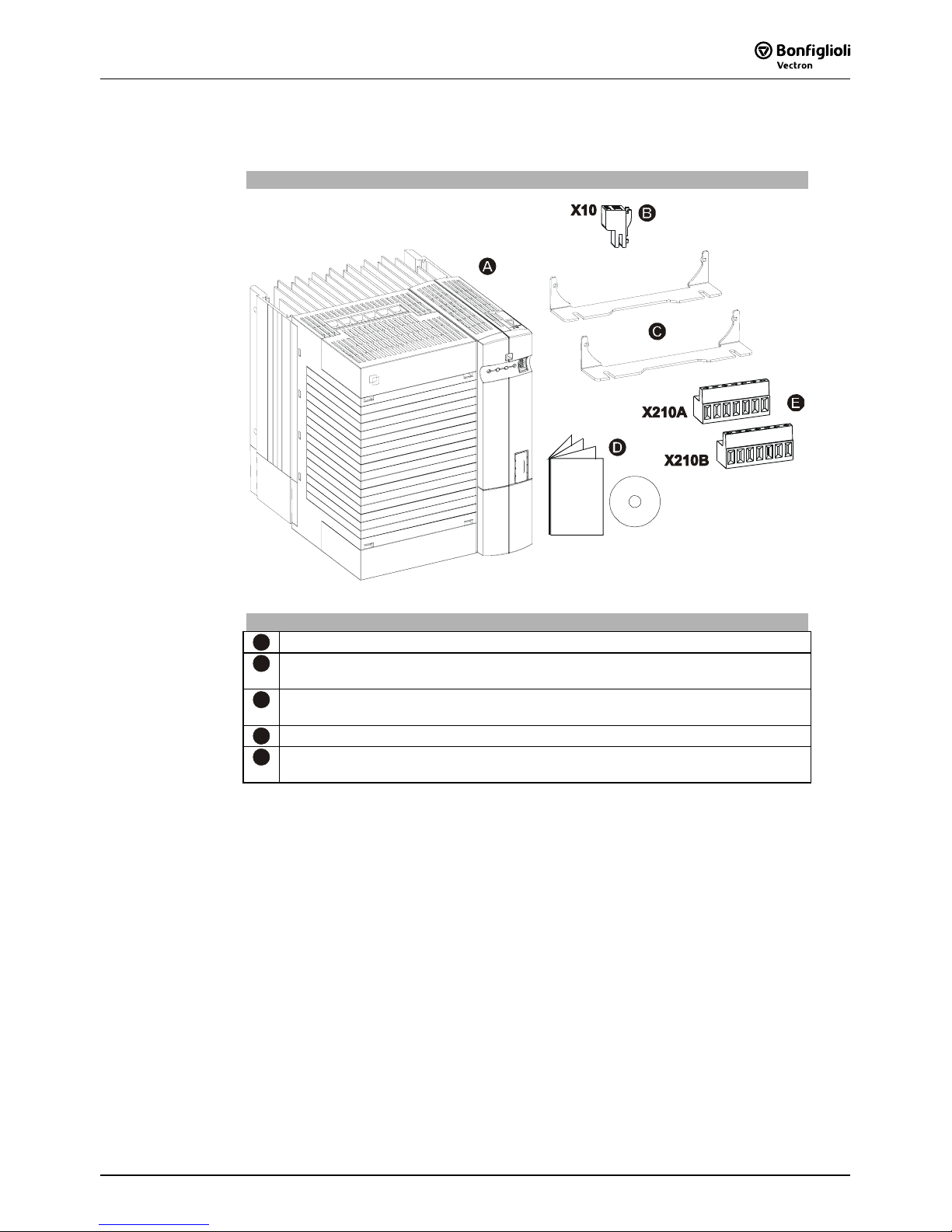
2 Scope of Supply
Thanks to the modular hardware components, the frequency inverters can be
integrated in the automation concept easily. The scope of delivery described can be
supplemented by optional components and adapted to the customer-specific
requirements. The plug-in type connection terminals enable a safe function and an
economical assembly.
2.1 Frequency Inverter (0.55 to 4.0 kW)
ACT 201 (230 V) and ACT 401 (400 V)
Power range 0.55 kW to 4.0 kW
Scope of Supply
A
Frequency inverter
B
Terminal strip X1 (Phoenix ZEC 1,5/ST7,5)
Plug-in terminals for mains connection and DC linking
C
Terminal strip X10 (Phoenix ZEC 1.5/3ST5.0)
Plug-in terminals for the relay output
D
Standard fixtures for vertical assembly
E
Brief Instructions and manuals on CD
F
Terminal strip X2 (Phoenix ZEC 1,5/ST7,5)
Plug-in terminal for brake resistor and motor connection
G
Control terminals X210A / X210B (Wieland DST85 / RM3.5)
Plug-in terminal for connection of the control signals
Note: Please check incoming goods for quality, quantity and nature without
delay. Obvious defects such as exterior damage of the packing and/or
the unit must be notified to the sender within seven days for insurance
reasons.

06/058
2.2 Frequency Inverter (5.5 to 15.0 kW)
ACT 401 (400 V)
Power range 5.5 kW to 15 kW
Scope of Supply
A
Frequency inverter
B
Terminal strip X10 (Phoenix ZEC 1.5/3ST5.0)
Plug-in terminals for the relay output
C
Standard fixtures with fixing bolts (M4x20, M4x60)
for vertical assembly
D
Brief Instructions and manuals on CD
E
Control terminals X210A / X210B (Wieland DST85 / RM3.5)
Plug-in terminal for connection of the control signals
Note: Please check incoming goods for quality, quantity and nature without
delay. Obvious defects such as exterior damage of the packing and/or the
unit must be notified to the sender within seven days for insurance
reasons.
06/05 9
2.3 Frequency Inverter (18.5 to 30.0 kW)
ACT 401 (400 V)
Power range 18.5 kW to 30 kW
Scope of Supply
A
Frequency inverter
B
Terminal strip X10 (Phoenix ZEC 1.5/3ST5.0)
Plug-in terminals for the relay output
C
Standard fixtures with fixing bolts (M4x20, M4x70)
for vertical assembly
D
Brief Instructions and manuals on CD
E
Control terminals X210A / X210B (Wieland DST85 / RM3.5)
Plug-in terminal for connection of the control signals
Note: Please check incoming goods for quality, quantity and nature without
delay. Obvious defects such as exterior damage of the packing and/or the
unit must be notified to the sender within seven days for insurance
reasons.

06/0510
3 Technical Data
3.1 Frequency Inverter 230 V (0.55 to 3.0 kW)
Type
ACT 201 -05 -07 -09 -11 -13 -15
Output, motor side
Recommended shaft output P kW 0.55 0.75 1.1 1.5 2.2 3.0 4)
Output current I A 3.0 4.0 5.4 5) 7.0 9.5 12.5
4) 5)
Overload current (60 s) I A 4.5 6.0 7.3 10.5 14.3 16.2
Overload current (1 s) I A 6.0 8.0 8.0 14.0 19.0 19.0
Output voltage U V 3 x 0 ... mains voltage
Protection - - Short circuit / earth fault proof
Rotary field frequency f Hz 0 ... 1000, depending on switching frequency
Switching frequency f kHz 2, 4, 8 (nom. operat. point), 12, 16
Output, brake resistor
min. brake resistor (U
dBC
= 385 V) R Ω 230 160 115 75 55 37
Input, mains side
Mains current 3) , 3ph/PE
1ph/N/PE ; 2ph/PE
I A
3.0
5.4
4.0
7.2
5.5
1)
9.5 2)
7.0
13.2
9.5
16.5 2)
10.5
1)
16.5
2) 4)
Mains voltage U V 184 ... 264
Mains frequency f Hz 45 ... 66
Fuse 3ph/PE
1ph/N/PE ; 2ph/PE
I A
6
10
10
16
16
20
16
20
UL type 250 VAC RK5, 3ph/PE
1ph/N/PE; 2ph/PE
I A
6
10
10
15
15
20
15
20
Mechanics
Dimensions: HxWxD mm 190x60x175 250x60x175
Weight (approx.) m kg 1.2 1.6
Degree of protection - - IP20 (EN60529)
Terminals A
mm
2
0.2 ... 1.5
Form of assembly - - vertical
Ambient conditions
Energy dissipation
(2 kHz switching frequency)
P W 43 53 73 84 115 170
Coolant temperature
T
n
°C 0 ... 40 (3K3 DIN IEC 721-3-3)
Storage temperature
T
L
°C -25 ... 55
Transport temperature
T
T
°C -25 ... 70
Rel. air humidity - % 15 ... 85; not condensing
If required by the customer, the switching frequency may be increased if the output current is
reduced at the same time. Comply with the applicable standards and regulations for this operating
point.
Output current
Switching frequency
Frequency inverter nominal power
2 kHz 4 kHz 8 kHz 12 kHz 16 kHz
0.55 kW 3.0 A 3.0 A 3.0 A 2.5 A 2.0 A
0.75 kW 4.0 A 4.0 A 4.0 A 3.4 A 2.7 A
1.1 kW 5.5 A 2) 5.5 A
2) 5)
5.4 A
2) 5)
4.5 A
2) 5)
3.7 A 5)
1.5 kW 7.0 A 7.0 A 7.0 A 5.9 A 4.8 A
2.2 kW 9.5 A 2) 9.5 A 2) 9.5 A 2) 8.0 A 2) 6.5 A
3.0 kW
2) 4)
12.5 A
1)
12.5 A
1) 5)
12.5 A
1) 5)
10.5 A
1) 5)
8.5 A 5)
1) Three-phase connection requires a commutating choke.
2)
One- and two-phase connection requires a commutating choke.
3)
Mains current with relative mains impedance 1% (see chapter„Electrical installation“)
4)
Maximum output current is 9.5 A for one- and two-phase connection.
5)’
Switching frequency is reduced in thermal limit range

06/05 11
3.2 Frequency Inverter 400 V (0.55 to 4.0 kW)
Type
ACT 401 -05 -07 -09 -11 -12 -13 -15 -18
Output, motor side
Recommended shaft output P kW 0.55 0.75 1.1 1.5 1.85 2.2 3.0 4.0
Output current I A 1.8 2.4 3.2 3.8 3) 4.2 5.8 7.8 9.0
3)
Overload current (60 s) I A 2.7 3.6 4.8 5.7 6.3 8.7 11.7 13.5
Overload current (1 s) I A 3.6 4.8 6.4 7.6 8.4 11.6 15.6 18.0
Output voltage U V 3 x 0 ... mains voltage
Protection - - Short circuit / earth fault proof
Rotary field frequency f Hz 0 ... 1000, depending on switching frequency
Switching frequency f kHz 2, 4, 8 (nom. operat. point), 12, 16
Output, brake resistor
Min. brake resistor (U
dBC
= 770 V) R Ω 930 634 462 300 300 220 148 106
Input, mains side
Mains current 2) 3ph/PE I A 1.8 2.4 2.8 1)3.3 1) 4.2 5.8 6.8 1) 7.8 1)
Mains voltage U V 320 ... 528
Mains frequency f Hz 45 ... 66
Fuses 3ph/PE I A 6 10
UL type 600 VAC RK5, 3ph/PE I A 6 10
Mechanics
Dimensions: HxWxD mm 190x60x175 250x60x175
Weight (approx.) m kg 1.2 1.6
Degree of protection - - IP20 (EN60529)
Terminals A
mm
2
0.2 ... 1.5
Form of assembly - - vertical
Ambient conditions
Energy dissipation
(2 kHz switching frequency)
P W 40 46 58 68 68 87 115 130
Coolant temperature
T
n
°C 0 ... 40 (3K3 DIN IEC 721-3-3)
Storage temperature
T
L
°C -25 ... 55
Transport temperature
T
T
°C -25 ... 70
Rel. air humidity - % 15 ... 85, not condensing
If required by the customer, the switching frequency may be increased if the output current is
reduced at the same time. Comply with the applicable standards and regulations for this operating
point.
Output current
Switching frequency
Frequency inverter nominal power
2 kHz 4 kHz 8 kHz 12 kHz 16 kHz
0.55 kW 1.8 A 1.8 A 1.8 A 1.5 A 1.2 A
0.75 kW 2.4 A 2.4 A 2.4 A 2.0 A 1.6 A
1.1 kW 3.2 A 1) 3.2 A 1) 3.2 A 1) 2.7 A 1) 2.2 A
1.5 kW 1) 3.8 A 3.8 A 3) 3.8 A 3) 3.2 A 3) 2.6 A 3)
1.85 kW 4.2 A 4.2 A 4.2 A 3.5 A 2.9 A
2.2 kW 5.8 A 5.8 A 5.8 A 4.9 A 3.9 A
3.0 kW 7.8 A 1) 7.8 A 1) 7.8 A 1) 6.6 A 1) 5.3 A
4.0 kW 9.0 A 1) 9.0 A
1) 3)
9.0 A
1) 3)
7.6 A
1) 3)
6.1 A
3)
1) Three-phase connection requires a commutating choke.
2)
Mains current with relative mains impedance 1% (see chapter„Electrical installation“)
3)
Switching frequency is reduced in thermal limit range

06/0512
3.3 Frequency Inverter 400 V (5.5 to 15.0 kW)
Type
ACT 401 -19 -21 -22 -23 -25
Output, motor side
Recommended shaft output P kW 5.5 7.5 9.2 11.0 15.0
Output current I A 14 18 22 3) 25 32
Overload current (60 s) I A 21.0 26.3 30.3 37.5 44.5
Overload current (1 s) I A 28.0 33.0 33.0 50.0 64.0
Output voltage U V 3 x 0 ... mains voltage
Protection - - Short circuit / earth fault proof
Rotary field frequency f Hz 0 ... 1000, depending on switching frequency
Switching frequency f kHz 2, 4, 8 (nom. operat. point), 12, 16
Output, brake resistor
Min. brake resistor (U
dBC
= 770 V) R Ω 80 58 48 48 32
Input, mains side
Mains current 2) 3ph/PE I A 14.2 15.8 1) 20.0 1) 26.0 28.2 1)
Mains voltage U V 320 ... 528
Mains frequency f Hz 45 ... 66
Fuses 3ph/PE I A 16 25 35
UL type 600 VAC RK5, 3ph/PE I A 20 30 40
Mechanics
Dimensions HxWxD mm 250x100x200 250x125x200
Weight (approx.) m kg 3.0 3.7
Degree of protection - - IP20 (EN60529)
Terminals A mm
2
0.2 ... 6 0.2 ... 16
Form of assembly - - vertical
Ambient conditions
Energy dissipation
(2 kHz switching frequency)
P W 145 200 225 240 310
Coolant temperature Tn °C 0 ... 40 (3K3 DIN IEC 721-3-3)
Storage temperature TL °C -25 ... 55
Transport temperature TT °C -25 ... 70
Rel. air humidity - % 15 ... 85, not condensing
If required by the customer, the switching frequency may be increased if the output current is
reduced at the same time. Comply with the applicable standards and regulations for this operating
point.
Output current
Switching frequency
Frequency inverter nominal power
2 kHz 4 kHz 8 kHz 12 kHz 16 kHz
5.5 kW 14.0 A 14.0 A 14.0 A 11.8 A 9.5 A
7.5 kW 18.0 A 1) 18.0 A 1) 18.0 A 1) 15.1 A 1) 12.2 A
9.2 kW 1) 23.0 A 22.7 A
3)
22.0 A
3)
18.5 A 3) 15.0 A
3)
11 kW 25.0 A 25.0 A 25.0 A 21.0 A 17.0 A
15 kW 32.0 A 1) 32.0 A 1) 32.0 A 1) 26.9 A 1) 21.8 A
1) Three-phase connection requires a commutating choke.
2)
Mains current with relative mains impedance 1% (see chapter„Electrical installation“)
3)
Switching frequency is reduced in thermal limit range

06/05 13
3.4 Frequency Inverter 400 V (18.5 up to 30 kW)
Type
ACT 401 -27 -29 -31
Motor-side output
Recommended motor shaft output P kW 18.5 22 30
Output current I A 40.0 45.0 60.0
Overload current (60 s) I A 60.0 67.5 90.0
Overload current (1 s) I A 80.0 90.0 120.0
Output voltage U V 3 x 0 ... mains voltage
Protection - - Short circuit / earth fault proof
Rotary field frequency f Hz 0 ... 1000, depending on switching frequency
Switching frequency f kHz 2, 4, 8 (nom. operat. point)
Brake resistor output
Min. brake resistor (U
dBC
= 770 V) R Ω 24 16
Mains-side input
Mains current 2) 3ph/PE I A 42.0 50.0 58.0 1)
Mains voltage U V 320 ... 528
Mains frequency f Hz 45 ... 66
Fuses 3ph/PE I A 50 50 63
UL type 600 VAC RK5, 3ph/PE I A 40 50 60
Mechanical
Dimensions HxWxD mm 250x200x290
Weight (approx.) m kg 8
Degree of protection - - IP20 (EN60529)
Terminals A mm
2
up to 25
Form of assembly - - vertical
Environmental conditions
Energy dissipation
(2 kHz switching frequency)
P W 420 470 750
Coolant temperature T
n
°C 0 ... 40 (3K3 DIN IEC 721-3-3)
Storage temperature TL °C -25 ... 55
Transport temperature TT °C -25 ... 70
Rel. air humidity - % 15 ... 85, not condensing
Depending on the customer-specific requirements, an increase of the switching frequency is
permissible if the output current is reduced. Comply with the applicable standards and regulations
for this operating point.
Output current
Switching frequency
Frequency inverter nominal power
2 kHz 4 kHz 8 kHz
18.5 kW 40.0 A 40.0 A 40.0 A
22 kW 45.0 A 45.0 A 45.0 A
30 kW 60.0 A 1) 60.0 A 1) 60.0 A 1)
1) Three-phase connection requires a commutating choke.
2)
Mains current with relative mains impedance 1% (see chapter "Electrical installation")

06/0514
3.5 Operation diagrams
The technical data of the frequency inverters refer to the nominal point which was
selected to enable a wide range of applications. A functionally and efficient
dimensioning (derating) of the frequency inverters is possible based on the following
diagrams.
Site altitude
100
85
60
40
20
55
45
3000
1000
2000 4000
3000
1000
2000
4000
Power reduction (Derating),
5%/1000 m above sea level,
h = 4000 m
max
max. coolant temperature,
3.3 °C/1000 m above sea level,
Mounting altitude in m above sea level Mounting altitude in m above sea level
Output current in %
Coolant temperature in °C
Coolant temperature
100
80
63
40
20
0 10
20
30
40 50 55
Power reduction (Derating)
2.5%/K upper 40 °C, T = 55 °C
max
Output current in
%
Coolant temperature in °C
Mains voltage
100
83
63
40
20
0 400
420
440
460
480
reduction of output current at constant power (Derating
)
0.22%/ V upper 400 V, U = 480 V
max
O
utput current in
%
Mains voltage in V

06/05 15
4 Mechanical Installation
The frequency inverters of degree of protection IP20 are designed, as a standard, for
installation in electrical cabinets.
• During installation, both the installation and the safety instructions as well as the
device specifications must be complied with.
Warning! To avoid serious physical injuries or major material damage, only
qualified persons are allowed to work on the devices.
Warning! During assembly, make sure that no foreign particles (e.g. filings, dust,
wires, screws, tools) can get inside the frequency inverter. Otherwise
there is the risk of short circuits and fire.
The frequency inverters comply with protection class IP20 only if the
covers and terminals are mounted properly.
The units may only be used if these requirements are met.
Caution! Mount the devices with sufficient clearance to other components so that
the cooling air can circulate freely. Avoid soiling by grease and air
pollution by dust, aggressive gases, etc.

06/0516
4.1 Frequency Inverter (0.55 to 4.0 kW)
The frequency inverter is mounted in a vertical position on the assembly panel by
means of the standard fittings.
The following illustration shows the different mounting possibilities.
Standard installation
b
b1
a1
a a2
c
c1
x
x
x 100 mm
≥
b1
Assembly is effected by inserting the long side of the fixing plate in the heat sink and
screwing it to the mounting plate.
The dimensions of the device and the installation dimensions are those of the
standard device without optional components and are given in millimeters.
Dimensions in mm Installation dimensions in mm
Frequency inverter
a b c a1 a2 b1 c1
0.55 kW ... 1.1 kW
190 60 175 210 ... 230 255 30 130
ACT 201
1.5 kW ... 3.0 kW
250 60 175 270 ... 290 315 30 130
0.55 kW ... 1.5 kW
190 60 175 210 ... 230 255 30 130
ACT 401
1.85 kW ... 4.0 kW
250 60 175 270 ... 290 315 30 130

06/05 17
4.2 Frequency Inverter (5.5 to 15 kW)
The frequency inverter is mounted in a vertical position on the assembly panel by
means of the standard fittings. The following illustration shows the standard fitting.
Standard installation
b
b1
a
a1 a2
c
x
x
c1
x 100 mm
≥
fixing bracket bottom
(fixing with screws )
M4x60
fixing bracket top
(fixing with screws )
M4x20
Assembly is done by screwing the two fixing brackets to the heat sink of the
frequency inverter and the assembly panel.
The frequency inverters are provided with fixing brackets, which are fitted using four
thread-cutting screws.
The dimensions of the device and the installation dimensions are those of the
standard device without optional components and are given in millimeters.
Dimensions in mm Installation dimensions in mm
Frequency inverter
a b c a1 a2 b1 c1
5.5 kW ... 9.2 kW
250 100 200 270 ... 290 315 12 133
11.0 kW ... 15.0 kW
250 125 200 270 ... 290 315 17.5 133

06/0518
4.3 Frequency Inverter (18.5 to 30 kW)
The frequency inverter is mounted in a vertical position on the assembly panel by
means of the standard fittings. The following illustration shows the standard fitting.
Standard installation
c
c1
x 100 mm
≥
x
a
a1
a2
b
b1
x
fixing bracket top
(fixing with screws )
M4x20
fixing bracket bottom
(fixing with screws )
M4x70
Assembly is done by screwing the two fixing brackets to the heat sink of the frequency
inverter and the assembly panel.
The frequency inverters are provided with fixing brackets, which are fitted using four
thread-cutting screws. The dimensions of the device and the installation dimensions
are those of the standard device without optional components and are given in
millimeters.
Dimensions in mm Installation dimensions in mm
Frequency inverter
a b c a1 a2 b1 c1
18.5 kW ... 30 kW
250 200 290 270 … 290 315 20 165

06/05 19
5 Electrical Installation
The electrical installation must be carried out by qualified staff according to the
general and regional safety and installation directives. For a safe operation of the
frequency inverter it is necessary that the documentation and the device
specifications be complied with during installation and commissioning. In the case of
special applications, you may also have to comply with further guidelines and
instructions.
Danger! When the frequency inverter is disconnected from power supply, the
mains, DC-link voltage and motor terminals may still be live for some
time. Wait for some minutes until the DC link capacitors have
discharged before starting to work at the unit.
The connecting cables must be protected externally, considering the maximum
voltage and current values of the fuses. The mains fuses and cable cross-sections are
to be selected according to EN 60204-1 and DIN VDE 0298 Part 4 for the nominal
operating point of the frequency inverter. According to UL/CSA, the frequency
inverter is suitable for operation at a supply network of a maximum of 480 VAC which
delivers a maximum symmetrical current of 5000 A (effective value) if protected by
fuses of class RK5. Only use copper cables with a temperature range of 60/75 °C.
Warning! The frequency inverters are to be grounded properly, i.e. large
connection area and with good conductivity. The leakage current of the
frequency inverters may be > 3.5 mA. According to EN 50178 a
permanent connection must be provided. The protective conductor
cross-section required for grounding the fixing plate must be at least 10
mm², or a second protective conductor must be installed electrically
parallel to the first one. In these applications, the cross-section must
correspond to the recommended cross-section of the wire.
Connection conditions
− The frequency inverter is suited for connection to the public or industrial supply
mains according to the technical data. If the transformer output of the supply
mains is ≤ 500 kVA, the optional mains commutation choke is only necessary for
the frequency inverters identified in the technical data. The other frequency
inverters are suitable for connection without a mains commutating choke with
relative mains impedance ≥ 1%.
− It must be checked, based on the specifications of EN 61000-3-2, if the devices
can be connected to the public supply means without taking additional measures.
The frequency inverters ≤ 9.2 kW with integrated EMC filter comply with the
emission limits of the product standard EN 61800-3 up to a motor cable length of
10 m, without additional measures being required. Increased requirements in
connection with the specific application of the frequency inverter are to be met
by means of optional components. Commutating chokes and EMC filters are
optionally available for the series of devices.
− Operation on unearthed mains (IT mains) is admissible after disconnection of the
Y capacitors in the interior of the device.
− Interference-free operation with residual-current device is guaranteed at a
tripping current ≥ 30 mA if the following points are observed:
− Pulse-current and alternating-current sensitive residual current devices (Type
A to EN 50178) in the case of a connection of frequency inverters with onephase power supply (L1/N)
− All-current sensitive residual current devices (Type B to EN 50178) in the case
of a connection of frequency inverters with two-phase (L1/L2) or three-phase
(L1/L2/L3) power supply.
− Use EMC filters with reduced leakage current or, if possible, do not use EMC
filters at all.
− The length of the shielded motor cable is ≤ 10 m and there are no additional
capacitive components between the mains or motor cables and PE.

06/0520
5.1 EMC Information
The frequency inverters are designed according to the requirements and limit values
of product norm EN 61800-3 with an interference immunity factor (EMI) for operation
in industrial applications. Electromagnetic interference is to be avoided by expert
installation and observation of the specific product information.
Measures
• Install the frequency inverters and commutating chokes on a metal mounting
panel. Ideally, the mounting panel should be galvanized.
• Provide proper equipotential bonding within the system or the plant. Plant
components such as control cabinets, control panels, machine frames, etc. must
be connected by means of PE cables.
• Connect the frequency inverter, the commutating choke, external filters and
other components to an earthing point via short cables.
• Keep the cables as short as possible, make sure that cables are installed properly
using appropriate cable clamps, etc.
• Contactors, relays and solenoids in the electrical cabinet are to be provided with
suitable interference suppression components.
A
Mains connection
The length of the mains supply cable is not
limited. However, it must be installed separate
from the control, data and motor cables.
B
DC link connection
The frequency inverters are to be connected to
the same mains potential or a common direct
voltage source. Cables longer than 300 mm are
to be shielded. The shield must be connected to
the mounting panel on both sides.
C
Control Connection
The control and signal cables must be kept physically separate from the power cables. The shield
of the control cables is to be connected to
ground potential properly, i.e. with good
conductivity, on both sides. Analog signal lines
are to be connected to the shield potential on
one side.
D
Motor and brake resistor
A
B
C
D
The shield of the motor cable is to be connected
to ground potential properly on both sides. On
the motor side use a metal compression gland.
On the frequency inverter side an appropriate
shield clamp is to be used. The signal cable used
for monitoring the motor temperature must be
kept separate from the motor cable. Connect the
shield of this line on both sides. If a brake
resistor is used, the connection cable must also
be shielded, and the shield is to be connected to
earth potential on both sides.
Attention! The frequency inverters meet the requirements of the low-voltage direc-
tive 73/23/EEC and the requirements of the EMC directive 89/336/EEC.
The EMC product standard EN 61800-3 relates to the drive system. The
documentation provides information on how the applicable standards
can be complied if the frequency inverter is a component of the drive
system. The declaration of conformity is to be issued by the supplier of
the drive system.

06/05 21
5.2 Block diagram
+10 V / 4 mA
MFI1
GND 10 V
6
X210A
+20 V / 180 mA
GND 20 V
S4IND
X210B
5
6
7
1
2
3
S3OUT
X
10
A
D
5
S3IND
4
S2IND
2
S1IND
7
S5IND
3
1
1
S6IND
GND 20 V
2
4
MFO1
S1OUT
3
CPU
+
-
L2 L3L1
X1
V
W
U
Rb1
X2
+
-
Rb2
I
U, I
A
B
C
D
E
F
A
Relay connection S3OUT
Change-over contact, response time approx. 40 ms, 240 V AC / 5 A, 24 V DC / 5 A
(ohmic)
B
Digital input S1IND
Digital signal, controller enable signal, response time approx. 16 ms (on), 10 µs (off),
U
max
= 30 V, 10 mA at 24 V, PLC compatible
C
Digital input S2IND ... S6IND
Digital signal: response time approx. 16 ms, U
max
= 30 V, 10 mA at 24 V, PLC com-
patible, frequency signal: 0...30 V, 10 mA at 24 V, f
max
= 150 kHz
D
Digital output S1OUT
Digital signal, 24 V, I
max
= 40 mA,
PLC compatible, overload and short-circuit proof
E
Multi-function output MFO1
Analog signal: 24 V, I
max
= 40 mA, pulse-width modulated, f
PWM
= 116 Hz
Digital signal: 24 V, I
max
= 40 mA,
frequency signal: 0...24 V, I
max
= 40 mA, f
max
= 150 kHz,
PLC compatible, overload and short-circuit proof
F
Multi-function input MFI1
Analog signal: resolution 12 Bit, 0...10 V (Ri = 70 kΩ), 0...20 mA (Ri = 500 Ω),
digital signal: response time approx. 16 ms, U
max
= 30 V, 4 mA at 24 V,
PLC compatible

06/0522
5.3 Mains Connection
The mains fuses and cable cross-sections are to be selected according to EN 60204-1
and DIN VDE 0298 Part 4 for the nominal operating point of the frequency inverter.
According to UL/CSA, approved Class 1 copper lines with a temperature range of
60/75°C and matching mains fuses are to be used for the power cables. The
electrical installation is to be done according to the device specifications and the
applicable standards and directives.
Caution! The control, mains and motor lines must be kept physically separate from
one another. The cables connected to the frequency inverters may not be
subjected to high-voltage insulation tests unless appropriate circuitry
measures are taken before.
5.3.1 Frequency Inverter (0.55 to 4.0 kW)
The mains connection of the frequency inverter is via plug-in terminal X1. Degree of
protection IP20 (EN60529) is only guaranteed if terminal X1 is plugged in.
Danger! Switch off power supply before connecting or disconnecting the keyed
plug-in terminal X1. Dangerous voltage may be present at the mains
terminals and the DC terminals even after the frequency inverter has been
disconnected safely from power supply. Wait for some minutes until the
DC link capacitors have discharged before starting the work.
• The unit may only be connected with the power supply switched off.
• Make sure that the frequency inverter is discharged.
Mains power connection 0.55 kW to 4.0 kW
X1
1ph / 230V AC
+
-
L1
L2 L3L1
N
PE
3ph / 230V AC
3ph / 400V AC
+
-
L1
L2 L3L1
L2
L3 PE
2ph / 230V AC
+
-
L1 L2 PE
L2
L3
L1
550 W … 1.1 kW
Phoenix ZEC 1,5/ .. ST7,5
0.2 … 1.5 mm
AWG 24 … 16
2
0.2 … 1.5 mm
AWG 24 … 16
2
0.25 … 1.5 mm
AWG 22 … 16
2
0.25 … 1.5 mm
AWG 22 … 16
2
2ph / 230V AC
+
-
L1
L1 L2 L3L1
L2
PE
1ph / 230V AC
+
-
L1
L1 L2
L3
L1
N
PE
1.5 kW … 3.0 kW
3ph / 230V AC
3ph / 400V AC
+
-
L1
L1 L2
L3
L1
L2
L3 PE
1.5 kW … 3.0 kW 1.5 kW … 4.0 kW
1
With a mains current above 10 A, the mains power connection 230 V 1ph/N/PE
and the mains power connection 230 V 2ph/N/PE are to be done on two
terminals.

06/05 23
5.3.2 Frequency Inverter (5.5 to 15.0 kW)
Danger! Switch off power supply before connecting or disconnecting the
mains cable to terminal X1 Dangerous voltage may be present at the
mains terminals and the DC terminals even after the frequency inverter
has been disconnected safely from power supply. Wait for some
minutes until the DC link capacitors have discharged before starting the
work.
• The unit may only be connected with the power supply switched off.
• Make sure that the frequency inverter is discharged.
Mains power connection 5.5 kW to 15.0 kW
0.2 … 6 mm
AWG 24 … 10
2
5.5 kW … 9.2 kW
WAGO Line 745 / 6qmm / RM7,5
0.2 … 6 mm
AWG 24 … 10
2
0.25 … 4 mm
AWG 22 … 12
2
0.25 … 4 mm
AWG 22 … 16
2
+
-
L1
L2 L3L1
L2
L3 PE
3ph / 400V AC
X1
0.2 … 16 mm
AWG 24 … 6
2
11 kW … 15 kW
WAGO Line 745 / 16qmm / RM10+1
5
0.2 … 16 mm
AWG 24 … 6
2
0.25 … 10 mm
AWG 22 … 8
2
0.25 … 10 mm
AWG 22 … 8
2
X1

06/0524
5.3.3 Frequency Inverter (18.5 to 30 kW)
Danger! Switch off power supply before connecting or disconnecting the mains
cable to terminal X1 Dangerous voltage may be present at the mains
terminals and the DC terminals even after the frequency inverter has been
disconnected safely from power supply. Wait for some minutes until the
DC link capacitors have discharged before starting the work.
• The unit may only be connected with the power supply switched off.
• Make sure that the frequency inverter is discharged.
Mains power connection 18.5 kW to 30 kW
0.5 … 35 mm
AWG 20 … 2
2
18.5 kW … 30 kW
PHOENIX MKDSP 25/ 6-15,00-
F
0.5 … 25 mm
AWG 20 … 4
2
1.00 … 25 mm
AWG 18 … 4
2
1.5 … 25 mm
AWG 16
… 4
2
+
-
L1
L2 L3L1
L2
L3 PE
3ph / 400V AC
X1
X1
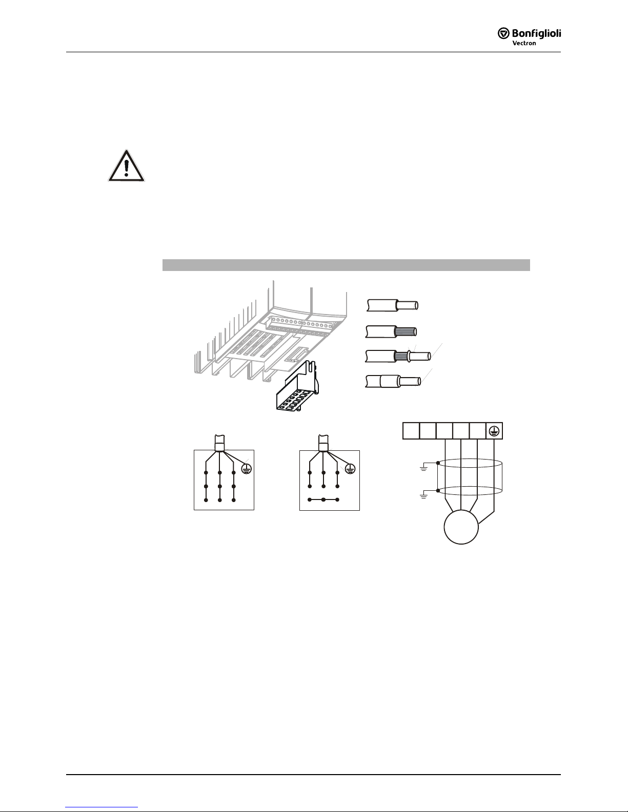
5.4 Motor Connection
The connection of the motor and the brake resistor to the frequency inverter is to be
done using shielded cables. The shield is to be connected to PE potential properly,
i.e. with good conductivity, on both sides. The control, mains and motor lines must
be kept physically separate from one another. The user must comply with the
applicable limits stipulated in the relevant national and international directives as
regards the application, the length of the motor cable and the switching frequency.
Permissible length of motor cable without output filter
Frequency inverter unshielded cable shielded cable
0.55 kW … 4.0 kW 50 m 25 m
5.5 kW … 15.0 kW 100 m 50 m
18.5 kW … 30.0 kW 150 m 50 m
The specified lengths of the motor cables must not be exceeded if no output filter is
installed. Upon request, we will check if longer motor cables can be used after taking
appropriate technical measures, e.g. use of low-capacitance cables and output filters.
Note: The frequency inverters ≤ 9.2 kW with integrated EMC filter comply with the
emission limits stipulated in EN 61800-3 if the motor cable is not longer than
10 m. Customer-specific requirements can be met by means of an optional
filter.
06/05 25
5.4.1 Frequency Inverter (0.55 to 4.0 kW)
The connection of the motor and the brake resistor to the frequency inverter is to be
done via plug-in terminal X2. Degree of protection IP20 (EN60529) is only
guaranteed if terminal X2 is connected.
Danger! Switch off power supply before connecting or disconnecting the
keyed plug-in terminal X2. Dangerous voltage may be present at the
motor terminals and the terminals of the brake resistor even after the
frequency inverter has been disconnected safely from power supply.
Wait for some minutes until the DC link capacitors have discharged
before starting to work at the unit.
• The unit may only be connected with the power supply switched off.
• Make sure that the frequency inverter is discharged.
Motor power connection 0.55 kW to 4.0 kW
Phoenix ZEC 1,5/ .. ST7,5
0.2 … 1.5 mm
AWG 24 … 16
2
0.2 … 1.5 mm
AWG 24 … 16
2
0.25 … 1.5 mm
AWG 22 … 16
2
0.25 … 1.5 mm
AWG 22 … 16
2
X2
Star connection
V
W
U
Delta connection
V
W
U
V
W
U
Rb2
Rb1
M
3~

06/0526
5.4.2 Frequency Inverter (5.5 to 15 kW)
The connection of the motor to the frequency inverter is to be done via terminal X2.
Danger! Switch off power supply before connecting or disconnecting the
motor cables to terminal X2. Dangerous voltage may be present at the
motor terminals and the terminals of the brake resistor even after the
frequency inverter has been disconnected safely from power supply.
Wait for some minutes until the DC link capacitors have discharged
before starting to work at the unit.
• The unit may only be connected with the power supply switched off.
• Make sure that the frequency inverter is discharged.
Motor power connection 5.5 kW to 15 kW
Star connection
V
W
U
Delta connection
V
W
U
5.5 kW … 9.2 kW
WAGO Line 745 / 6qmm / RM7,5
0.2 … 6 mm
AWG 24 … 10
2
0.2 … 6 mm
AWG 24 … 10
2
0.25 … 4 mm
AWG 22 … 12
2
0.25 … 4 mm
AWG
22 … 1
6
2
11 kW … 15 kW
WAGO Line 745 / 16qmm / RM10+1
5
0.2 … 16 mm
AWG 24 … 6
2
0.2 … 16 mm
AWG 24 … 6
2
0.25 … 10 mm
AWG 22 … 8
2
0.25 … 10 mm
AWG
22 …
8
2
X2
X2
V
W
U
Rb2
Rb1
M
3~

06/05 27
5.4.3 Frequency Inverter (18.5 to 30 kW)
The connection of the motor to the frequency inverter is to be done via terminal X2.
Danger! Switch off power supply before connecting or disconnecting the
motor cables to terminal X2. Dangerous voltage may be present at the
motor terminals and the terminals of the brake resistor even after the
frequency inverter has been disconnected safely from power supply.
Wait for some minutes until the DC link capacitors have discharged
before starting to work at the unit.
• The unit may only be connected with the power supply switched off.
• Make sure that the frequency inverter is discharged.
Motor power connection 18.5 kW to 30 kW
V
W
U
Delta connection
V
W
U
0.5 … 35 mm
AWG 20 … 2
2
18.5 kW … 30 kW
PHOENIX MKDSP 25/ 6-15,00-F
0.5 … 25 mm
AWG 20 … 4
2
1.00 … 25 mm
AWG 18 … 4
2
1.5 … 25 mm
AWG 16
… 4
2
X
2
V
W
U
Rb2
Rb1
M
3~
X
2

06/0528
5.5 Connection of a Brake Resistor
Connection of a brake resistor is done via terminal X2.
Danger! Switch off power supply before connecting or disconnecting the brake
resistor cables to terminal X2. Dangerous voltage may be present at the
motor terminals and the terminals of the brake resistor even after the
frequency inverter has been disconnected safely from power supply. Wait
for some minutes until the DC link capacitors have discharged before
starting to work at the unit.
• The unit may only be connected with the power supply switched off.
• Make sure that the frequency inverter is discharged.
Caution! The brake resistor must be equipped with a temperature switch. The
temperature switch must disconnect the frequency inverter from mains
supply if the brake resistor is overloaded.
5.5.1 Frequency Inverter (0.55 to 4.0 kW)
Degree of protection IP20 (EN60529) is only guaranteed if terminal X2 is connected.
Connection of brake resistor with temperature switch
X2
V WU
Rb2Rb1
R
b
T1
Rb1 Rb2
T2
X
2
5.5.2 Frequency Inverter (5.5 to 15 kW)
Connection of brake resistor with temperature switch
X2
R
b
T1
Rb1 Rb2
T2
V WU
Rb2Rb1
X
2

06/05 29
5.5.3 Frequency Inverter (18.5 to 30 kW)
Connection of brake resistor with temperature switch
R
b
T1
Rb1 Rb2
T2
V WU
Rb2Rb1
X2
X
2
5.6 Control Terminals
The control and software functionality can be freely configured to ensure a reliable
and economical operation. The operating instructions describe the factory settings of
the standard connections in the relevant
Configuration 30 as well as the software
parameters to be set up.
Caution! Switch off power supply before connecting or disconnecting the keyed
control inputs and outputs. Otherwise, components may be damaged.
• The unit may only be connected with the power supply switched off.
• Make sure that the frequency inverter is discharged.
Control Terminals
0.14 … 1.5 mm
AWG 30 … 16
2
Wieland DST85 / RM3,5
0.14 … 1.5 mm
AWG 30 … 16
2
0.25 … 1.0 mm
AWG 22 … 18
2
0.25 … 0.75 mm
AWG 22 … 20
2
0.2 … 0.3 Nm
1.8 … 2.7 lb-in

06/0530
Control terminal X210A
Ter. Description
1 Voltage output 20 V, I
max
=180 mA 1)
2 Ground / GND 20 V
3 Digital input S1IND, U
max
=30 V, 10 mA at 24 V, PLC compatible,
response time approx. 16ms (on), 10 µs (off)
4 Digital input EM-S2IND, U
max
=30 V, 10 mA at 24 V, PLC compatible,
response time approx. 16 ms
5 Digital input EM-S3IND, U
max
=30 V, 10 mA at 24 V, PLC compatible,
response time approx. 16 ms
6 Digital input S4IND, U
max
= 30 V, 10 mA at 24 V, PLC compatible,
frequency signal: 0...30 V, 10 mA at 24 V, f
max
= 150 kHz
7 Digital input S5IND, U
max
= 30 V, 10 mA at 24 V, PLC compatible,
frequency signal: 0...30 V, 10 mA at 24 V, f
max
= 150 kHz
Control terminal X210B
Ter. Description
1 Digital input S6IND, U
max
=30 V, 10 mA at 24 V, PLC compatible,
response time approx. 16 ms
2 Ground / GND 20 V
3 Digital output S1OUT, U=24 V, I
max
=40 mA, overload and short-circuit proof
4 Multi-function output MFO1,
analog signal: U=24 V, I
max
=40 mA, pulse-width modulated, f
PWM
=116 Hz
digital signal: U=24 V, I
max
=40 mA, overload and short-circuit proof,
frequency signal: 0...24 V, I
max
=40 mA, f
max
=150 kHz
5 Reference output 10 V, I
max
=4 mA
6 Multi-function input MFI1,
analog signal: resolution 12 Bit, 0...+10 V (Ri = 70 kΩ), 0...20 mA (Ri = 500 Ω),
digital signal: response time approx. 16 ms, U
max
= 30 V, 4 mA at 24 V,
PLC compatible
7 Ground / GND 10 V
1)
The power supply at terminal X210A.1 may be loaded with a maximum current
of I
max
= 180 mA. The maximum current available is reduced by the digital
output S1OUT and multifunctional output MFO1.
5.6.1 Relay Output
By default, the freely programmable relay output is linked to the monitoring function
(factory setting). The logic link to various functions can be freely configured via the
software parameters. Connection of the relay output is not absolutely necessary for
the function of the frequency inverter.
Relay Output
1
2
3
0.2 … 1.5 mm
AWG 24 … 16
2
Phoenix ZEC 1,5/3ST5,0
0.2 … 1.5 mm
AWG 24 … 16
2
0.25 … 1.5 mm
AWG 22 … 16
2
0.25 … 1.5 mm
A
WG 22 … 16
2
S3OUT
X10
X10
Control terminal X10
Ter. Description
1 ... 3 Relay output, floating change-over contact, response time approx. 40 ms,
max. contact load, make contact 5 A / 240 V AC, 5 A (ohmic) / 24 V DC
max. contact load, break contact 3 A / 240 V AC, 1 A (ohmic) / 24 V DC

06/05 31
5.6.2 Control Terminals – Terminal Diagram
The control hardware and the software of the frequency inverter are freely
configurable to a great extent. Certain functions can be assigned to the control
terminals, and the internal logic of the software modules can be freely selected.
In these brief instructions, the sensor-less control and the sensor-less field oriented
control are described in Configuration 110 and Configuration 410, respectively
5.6.2.1 Configuration 110 – Sensorless Control
Configuration 110 contains the functions for variable-speed control of a 3-phase
machine in a wide range of standard applications. The motor speed is set according
to the selected ratio of the reference frequency to the necessary voltage.
Control terminal X210A
X210A.1 Supply voltage +20V
X210A.2 Ground 20 V
X210A.3 Controller release / error acknowl-
edgment
X210A.4 Start of clockwise operation
X210A.5 Start of anticlockwise operation
X210A.6 Data set change-over 1
X210A.7 Data set change-over 2
Control terminal X210B
X210B.1 Motor thermal contact
X210B.2 Ground 20 V
X210B.3 Operating message
X210B.4 Analog signal of actual frequency
X210B.5 Supply voltage +10V
Reference value potentiometer
X210B.6 Reference speed 0 ...+10 V
GND 20 V
S1OUT
MFO1A
+10 V/ 4 mA
MFI1A
GND 10 V
1
2
3
4
5
6
7
X210A
+20 V/180 mA
GND 20 V
S1IND
S2IND
S3IND
S4IND
S5IND
S6IND
X210B
1
2
3
4
5
6
7
M
V
+
+
-
X210B.7 Ground 10 V

06/0532
5.6.2.2 Configuration 410 –
Sensorless Field-Oriented Control
Configuration 410 contains the functions for sensorless, field-oriented control of a 3-
phase machine. The current motor speed is determined from the present currents
and voltages in combination with the machine parameters. Separate control of torque
and flux-forming current enables high drive dynamism at a high load moment.
Control terminal X210A
X210A.1 Supply voltage +20V
X210A.2 Ground 20 V
X210A.3 Controller release / error acknowl-
edgment
X210A.4 Start of clockwise operation
X210A.5 Start of anticlockwise operation
X210A.6 Data set change-over 1
X210A.7 Data set change-over 2
Control terminal X210B
X210B.1 Motor thermal contact
X210B.2 Ground 20 V
X210B.3 Operating message
X210B.4 Analog signal of actual frequency
X210B.5 Supply voltage +10V
Reference value potentiometer
X210B.6 Reference speed 0 ...+10 V
GND 20 V
S1OUT
MFO1A
+10 V/4 mA
MFI1A
GND 10 V
1
2
3
4
5
6
7
X210A
+20 V/180 mA
GND 20 V
S1IND
S2IND
S3IND
S4IND
S5IND
S6IND
X210B
1
2
3
4
5
6
7
M
V
+
+
-
X210B.7 Ground 10 V

06/05 33
5.7 Optional Components
Thanks to the modular hardware components, the frequency inverters can be
integrated in the automation concept easily. The standard and optional modules are
recognized during the initialization, and the controller functionality is adjusted
automatically. For the information required for installation and handling of the
optional modules, refer to the corresponding documentation.
Danger! The hardware modules at slots B and C may only be assembled and
disassembled after the frequency inverter has been disconnected safely
from power supply. Wait for some minutes until the DC link capacitors
have discharged before starting the work.
• The unit may only be connected with the power supply switched off.
• Make sure that the frequency inverter is discharged.
Hardware modules
A
Control Unit KP500
Connection of the optional control unit KP500 or an interface
adapter KP232.
B
Communication module CM
Plug-in section for connection to various communication
protocols:
CM-232: RS232 interface
CM-485: RS485 interface
CM-PDP: Profibus-DP interface
CM-CAN: CANopen interface
C
Extension module EM
A
B
C
Slot for customer-specific adaptation of the control inputs
and outputs to various applications:
EM-ENC: extended speed sensor evaluation
EM-RES: resolver evaluation
EM-IO: analog and digital inputs and outputs
EM-SYS: system bus
(system bus in combination with CM-CAN communication module upon request)
Attention! If two optional components with CAN-Protocol controller are installed,
the system bus interface in the EM extension module is deactivated!

06/0534
6 Control Unit KP500
The optional KP500 control unit is a practical tool for controlling the frequency inverter
and setting and displaying the frequency inverter parameters.
The control unit is not absolutely necessary for the operation of the frequency inverter
and can be plugged on when required.
A
B
C
D
E
F
G
H
I
J
Keys
A
RUN Used for starting the drive and opening the CTRL menu.
Press the RUN key to open the motor potentiometer function.
STOP Used for opening the CTRL menu, stopping the drive and acknowledging
faults
J
� � Used for navigating in the menu structure and selecting parameters.
Increasing/decreasing of parameter values.
ENT Used for opening parameters or switching to another menu within the menu
structure. Confirmation of the selected function or the set parameter.
ESC Used for aborting parameters or switching back to the previous menu within
the menu structure. Canceling the function or resetting the parameter
value.
FUN Used for switching over the key function, access to special functions.
Display
B
Three-digit 7-segment display to show the parameter number
C
One-digit 7-segment display for display of the active data record, direction of
rotation etc.
D
Display of the selected menu branch:
VAL Display actual values
PARA Select parameters and adjust parameter values.
CTRL Select a function for adjustment and/or display via the control unit:
SEtUP guided commissioning
CtrL motor potentiometer and jog function
E
Status and operating messages:
WARN Warning about a critical operating behavior
FAULT Message indicating that the unit was switched off due to a fault
RUN Flashing: signals readiness for operation
Lights up: signals that the unit is operating and the output stage is enabled
REM Active remote control via interface connection
F Function switch-over with the FUN key
F
Five-digit 7-segment display for display of parameter value and sign
G
Physical unit of the parameter value displayed
H
Active acceleration or deceleration ramp
I
Current direction of rotation of the drive

06/05 35
6.1 Actual Value Menu (VAL)
In the VAL menu branch, the control unit displays a variety of actual values,
depending on the configuration selected and the options installed. The parameters
and basic software functions linked to the corresponding actual value are
documented in the operating instructions.
ENT
ESC
ENT
ESC
A
B
C
D
E
A
Use the arrow keys to select the required number from the actual values
displayed in numerical order.
In the current record, the record-related actual value parameters are displayed,
including the corresponding data record number. The seven-segment display
shows data record 0 if the actual values in the four data sets are identical.
Keys
� + � Display the actual value parameter upon switch-on.
FUN , � Display last actual value parameter (highest number).
FUN , � Display first actual value parameter (lowest number).
B
Use the ENT key to select the parameter. The parameter is displayed including
its current value, unit and the active data record.
C
During commissioning, operation and error analysis, it is possible to monitor
each actual value parameter specifically.
Some of the actual value parameters are arranged in the four available data
records. If the parameter values in the four data records are identical, the
actual value is displayed in data record 0. If the actual values in the four data
records are different, diFF is displayed in data record 0.
Keys
� , �
Switch to another of the data set in the case of related actual
values.
FUN , � Determine maximum value and display it permanently.
FUN , � Determine minimum value and display it permanently.
FUN , ENT
Display of mean value of the actual value during the monitoring
period.
D
Use the ENT key to save the selected actual value as a parameter displayed at
switch-on. The message SEt (with parameter number) is displayed for a short
time. When the frequency inverter is switched on the next time, this actual
value will be displayed automatically.
E
After saving the parameter, you can monitor and display the value again. Use
the ESC key to switch to the parameter selection of the VAL menu branch.

06/0536
6.2 Parameter Menu (PARA)
The parameters to be configured during the guided commissioning were selected
from common applications and can be supplemented as required by further settings
in the PARA menu branch. The parameters and basic software functions linked to the
corresponding actual value are documented in the operating instructions.
ENT
ESC
ENT
ESC
A
B
C
D
E
A
Use the arrow keys to select the required number from the parameters
displayed in numerical order. The parameter number is displayed with the
active data set (flashes).
In the current data set, the related parameters are displayed, including the
corresponding data set number. The seven-segment display shows data set 0 if
the parameter values in the four data sets are identical.
Keys
� + � Change to the last parameter edited.
FUN , � Display of last parameter (highest number).
FUN , � Display of first parameter (lowest number).
B
Use the ENT key to select the parameter. The parameter is displayed including
its value, unit and the active data set. If settings are edited in data set 0, the
parameter values are changed in the four data sets.
C
Use the arrow keys to adjust the parameter value or to select an operation
mode. The adjustment possibilities you have depend on the parameter.
Keep the arrow keys pressed for a while to change the displayed values quickly.
If you release the keys again, the speed at which the values change is reduced
again.
If the parameter value starts to flash, the speed at which the values change is
reset to the initial value again.
Keys
� + � Set parameter to factory setting.
FUN , � Set parameter to highest value.
FUN , � Set parameter to smallest value.
FUN , ENT
Change of the data set in the case of data set related
parameters.
D
Use the ENT key to save the parameter. For a short time, the message SEt
including the parameter number and the data set is displayed.
To leave the parameter unchanged, press the ESC key.
Messages
Err1: EEPrO Parameter has not been saved.
Err2: StOP
Parameter can only be read (i.e. not edited) when the unit is in
operation.
Err3: Error Other error
E
After saving the parameter, you can edit the value again or return to the
parameter selection menu by pressing the ESC key.

06/05 37
6.3 Controlling the Motor via the Control Unit
The control unit enables controlling the connected motor in accordance with the
selected operation mode of parameter
Local/Remote 412.
Note: In order to be able to control the drive via the control unit, the digital
controller input S1IND must be connected and set to "High-Signal" in
order to enable the output stage.
Warning! Switch off power supply before connecting and disconnecting control
terminal S1IND.
When the frequency inverter is disconnected from power supply,
dangerous voltage may still be present at the mains, DC link voltage
and motor terminals for some time. Wait for some minutes until the DC
link capacitors have discharged before starting to work at the unit.
• The unit may only be connected with the power supply switched off.
• Verify that the frequency inverter is de-energized.
: When the RUN key was pressed, the drive was in operation already.
The CTRL menu branch can be accessed via the navigation
within the menu structure. The CtrL function contains subfunctions which are displayed according to the operating point
of the frequency inverter.
Press the RUN key at any point in the menu structure to switch
to the motorpoti function Pot or the internal reference value
int if the drive is already in operation.
Motor potentiometer function Pot
Use the arrow keys to adjust the output frequency of the
frequency inverter from the
Minimum Frequency 418 to the
Maximum Frequency 419. The acceleration corresponds to
the factory settings (2 Hz/s) for parameter
Ramp Keypad-
Motorpoti
473. The parameters Acceleration (Clockwise) 420
and
Deceleration (Clockwise) 421 are considered in the case
of low acceleration values.

06/0538
Internal reference value int
The drive is in operation, i.e. output signals are present at the
frequency inverter and the current actual value is displayed.
Press an arrow key to switch to the motor potentiometer
function Pot. The current frequency value is taken over in the
motor potentiometer function Pot.
JOG frequency JOG
This function is useful for manual setup and positioning of a
machine. The frequency of the output signal is set to the
entered value if the FUN key is pressed.
• Press FUN key to switch from the internal reference value
int or the motor potentiometer function Pot to the
JOG-
Frequency
489.
• Keep the FUN key pressed and press the arrow keys to
adjust the required frequency.
(The frequency value last adjusted is saved as the
JOG-
Frequency
489.)
• Release the FUN key to stop the drive.
(The display returns to the previous function Pot or int.)
Key functions
ENT
Reversal of the direction of rotation independent of the control signal on
the terminals Clockwise S2IND or Anticlockwise S3IND.
ESC Cancel function and return to the menu structure.
FUN
Switch from internal set point int or rather motor potentiometer function
Pot to JOG frequency; the drive starts.
Release the key to switch to the sub-function and stop the drive.
RUN Start drive; alternative to control signal S2IND or S3IND
STOP Stop drive; alternative to control signal S2IND or S3IND
Attention! If you press the ENT key, the direction of rotation is changed
independent of the signal on the terminals Clockwise S2IND or
Anticlockwise S3IND.
If the
Minimum Frequency 418 has been set to 0.00 Hz, the direction
of rotation of the motor changes as soon as the sign of the reference
frequency value changes.

06/05 39
7 Commissioning of the Frequency Inverter
7.1 Switching on Mains Voltage
After completion of the installation work, make sure to check all control and power
connections again before switching on the mains voltage. If all electrical connections
are correct, make sure that the frequency inverter is not released (control input
S1IND open). After power-up, the frequency inverter carries out a self-test and the
relay output (X10) reports "Fault".
After a few seconds, the self-test is complete; the relay (X10) picks up and signals
"no fault ".
If the unit is in "as-delivered" condition or after resetting the unit to the factory
settings, the guided commissioning procedure is started automatically. On the control
unit, the "SetUP" menu from the menu branch CTRL is displayed.
7.2 Setup Using the Control Unit
The guided commissioning of the frequency inverter determines all parameter
settings relevant to the required application. The available parameters were selected
based on known standard drive applications. This facilitates the selection of the
important parameters. After successful completion of the SETUP routine, the actual
value
Actual Frequency 241 from the VAL menu branch is displayed on the control
unit. Now, the user should check whether further parameters are relevant for the
application.
Note: The guided commissioning contains the function for parameter identifi-
cation. The parameters are determined by way of measurement and set
accordingly. In the case of higher requirements as regards the accuracy
of the speed/torque control, you should carry out the guided
commissioning procedure once again under operating conditions
because part of the machine data depends on the operating temperature.
When the unit is in "as-delivered" condition, the guided
commissioning procedure is started automatically. After successful
commissioning, the guided commissioning can be carried out again
later via the sub-menu CTRL.
• Use the ENT key to switch to the CTRL sub-menu.
• In the CTRL sub-menu, select the menu item "SEtUP" and
confirm by pressing the ENT key.
• Use the ENT key to select parameter Configuration 30.
The available configurations are displayed automatically depending
on the selected
Control Level 28.
• Use the arrow keys to enter the number of the required
configuration. (for a description of the configurations, refer to
the following chapter)
If the setup was changed, the hardware and software functionality
will be configured. The message "SEtUP" is displayed again.
Confirm this message by pressing the ENT key in order to continue
the commissioning procedure.
• Switch to the next parameter.
• After initialization, confirm the selected configuration by
pressing the ENT key.
• Continue the guided commissioning procedure according to the
following chapters.
ENT
ENT

06/0540
7.2.1 Configuration
The software of the frequency inverter offers several configuration options. These
differ with respect to the way in which the drive is controlled. Parameter
Configuration 30 determines the assignment and basic function of the control inputs
and outputs as well as the software functions. Analog and digital inputs can be
combined and complemented by optional communication protocols as further
reference value sources. In these brief instructions, the sensor-less control and the
sensor-less field oriented control are described in Configuration 110 and Configuration
410, respectively.
Configuration 110, sensorless control
Configuration 110 contains the functions for variable-speed control of a 3-phase
machine in a wide range of standard applications. The motor speed is set according to
the V/f characteristic in accordance with the voltage/frequency ratio.
Configuration 410, sensorless field-oriented control
Configuration 410 contains functions for sensorless, field-oriented control of a 3-phase
machine. The current motor speed is determined from the present currents and
voltages in combination with the machine parameters. In this configuration, parallel
connection of several 3-phase motors is possible to a limited extent only.
7.2.2 Data Set
Data set change-over enables the selection of one of four data sets for storing
parameter settings. The default setting dS0 is recommended. If data set 0 is selected
(factory setting), the parameter values saved in data set 0 are copied to data sets 1 to
4. In this way, all values determined during the guided commissioning are saved in all
data sets. The frequency inverter uses data set 1 as the active data set. For more
information, refer to the operating instructions.
Data Set Setup
Parameter dS Function
0 All data sets (DS0)
1 Data set 1 (DS1)
2 Data set 2 (DS2)
3 Data set 3 (DS3)
4 Data set 4 (DS4)
7.2.3 Motor Type
The properties of the control functions and methods to be set vary depending on the
motor which is connected. The parameter
Motor type 369 offers a range of motor
variants with the corresponding table values. The verification of the entered rated
values and the guided commissioning are carried out on the basis of the
parameterized motor type. The selection of motor types varies depending on the
requirements of the different control methods. In instructions the functionality and
operating performance are described for 3-phase motors.
Caution! Polling and presetting of parameter values depends on the operation mode
selected for parameter
Motor type 369.
If the motor type is not entered correctly, the drive may be damaged.

06/05 41
Operation mode Function
0 - Unknown The motor is not a standard type.
1 - Asynchronous Three-phase asynchronous motor, squirrel cage
2 - Synchronous Three-phase synchronous motor
3 - Reluctance Three-phase reluctance motor
10 - Transformer Transformer with three primary windings
When the motor type is specified, the machine data must be entered. This is described
in the following chapter. The data are polled in accordance with the table below.
7.2.4 Machine Data
The machine data to be entered during the guided commissioning procedure are
indicated on the type plate or the data sheet of the motor. The factory settings of the
machine parameters are based on the nominal data of the frequency inverter and the
corresponding four-pole three-phase motor. The entered and calculated machine data
are checked for plausibility during the guided commissioning procedure. The user
should verify the factory-set rated data of the three-phase motor.
U
FUN, IFUN, PFUN
are rated values of the frequency inverter.
Parameter Settings
No. Description Min. Max. Fact. sett.
370 Rated Voltage 0.17⋅U
FUN
2⋅U
FUN
U
FUN
371 Rated Current 0.01⋅I
FUN
10⋅o ⋅ I
FUN
I
FUN
372 Rated Speed 96 min-1 60 000 min-1 nN
374 Rated Cosinus Phi 0.01 1.00 cos (ϕ)N
375 Rated Frequency 10.00 Hz 1000.00 Hz 50.00
376 Rated Mech. Power 0.01⋅P
FUN
10⋅P
FUN
P
FUN
• Use the arrow keys to select the required parameter and edit the parameter
value.
• Use the ENT key to confirm the selected parameter and the parameter values
entered.
Attention! The rated data of the motor are to be entered according to the
specifications on the rating plate for the motor connection type used
(star or delta connection). If the data entered deviate from the rating
plate, the parameters will not be identified correctly.
7.2.5 Plausibility check
After the machine data (and the speed sensor data, if applicable) have been entered,
the calculation or examination of the parameters is started automatically. The display
changes over to "CALC" for a short time. If the verification of the machine data is
successful, the guided commissioning procedure continues with the identification of
the parameters.
Verification of the machine data should only be skipped by experienced users. The
configurations contain complex control processes which depend to a large degree on
the correctness of the machine parameters entered.

06/0542
The warning and error messages displayed during the verification process have to be
observed. If a critical condition is detected during the guided commissioning, it is
displayed by the control unit. Depending on the deviation from the expected
parameter value, either a warning or an error message is displayed.
− To ignore the warning or error messages, press the ENT key. The guided
commissioning is continued. However, it is recommended that the data be
checked and corrected if necessary.
− To correct the entered parameter values after the warning or error message,
press the ESC key. Use the arrow keys to switch to the parameter value which is
to be corrected.
Warning Messages
Code Measures / Remedy
SA000
No warning message present. This message can be read out via an
optional communication module.
SA001
The value of the parameter
Rated Voltage 370 is out of the rated voltage
range of the frequency inverter. The maximum reference voltage is
indicated on the nameplate of the frequency inverter.
SA002
The calculated efficiency is in the limit range for a three-phase motor.
Check the values entered for the parameters
Rated Voltage 370, Rated
Current
371 and Rated Mech. Power 376.
SA003
The value entered for parameter
Rated Cosinus Phi 374 is outside of the
normal range (0.6 to 0.95). Check the value.
SA004
The calculated slip for an asynchronous motor is in the limit range.
Check the values entered for parameters
Rated Speed 372 and Rated
Frequency
375.
If an error message is displayed, the rated values must be checked and corrected.
The guided commissioning procedure is repeated until the rated values have been
entered correctly. Aborting the guided commissioning procedure by pressing ESC key
should only be done be expert users because it may be possible that rated values
have not been entered or determined correctly.
Error Messages
Code Measures / Remedy
SF000 No error message exists
SF001
The value entered for parameter
Rated Current 371 is too low. Correct the
value.
SF002
The value for parameter
Rated Current 371 is too high, referred to
parameters
Rated Mech. Power 376 and Rated Voltage 370. Correct the
values.
SF003
The value entered for parameter
Rated Cosinus Phi 374 is wrong (greater
than 1 or smaller than 0.3). Correct the value.
SF004
The calculated slip frequency is negative. Correct the values entered for
parameters
Rated Speed 372 and Rated Frequency 375.
SF005
The calculated slip frequency is too high.
Correct the values entered for parameters
Rated Speed 372 and Rated
Frequency
375.
SF006
The calculated total output of the drive is lower than the rated power.
Correct the value entered for parameter
Rated Mech. Power 376.
SF007
The set configuration is not supported by the guided commissioning. For
parameter
Configuration 30, select one of the configurations described in
these operating instructions.

06/05 43
7.2.6 Parameter identification
In addition to the parameterized rated data, the selected configuration demands
knowledge of further machine data not stated on the rating plate of the three-phase
machine. In addition to entering the rated motor parameters or as an alternative, the
required machine data can also be measured during the guided commissioning
process. The machine data are measured while the drive is at a standstill. The
measured values are entered in the parameter automatically either directly or after
the calculation. The procedure and the duration of the parameter identification
depend on the type of machine connected and the device.
After checking the machine data entered, the guided commissioning switches to the
parameter identification.
Confirm the display "PAidE" by pressing the ENT key.
During the parameter identification, the connected load is measured.
The safety functions of the frequency inverter avoid a release of the power unit if no
signal is present at digital input S1IND. If a signal was already applied at the
beginning of the guided commissioning, the "FUF" message is not displayed.
Note: The parameter identification feature of the frequency inverter requires
the presence of a signal at digital input S1IND for release of the power
unit.
Warning! Verify that the keyed control inputs and outputs are free of power before
connecting or disconnecting.
When the frequency inverter is disconnected from power supply, the
mains, DC-link voltage and motor terminals may still be live for some
time. Wait for some minutes until the DC link capacitors have discharged
before starting to work at the unit.
• The unit may only be connected with the power supply switched off.
• Make sure that the frequency inverter is discharged.
Confirm the final "rEAdY" message by pressing the ENT key.
Canceling the operation with the ESC key or withdrawing the release signal S1IND
results in an incomplete take-over of the values.
Note: In the case of higher requirements as regards the accuracy of the
speed/torque control, you should carry out the guided commissioning
procedure once again under operating conditions because part of the
machine data depends on the operating temperature.
During this procedure, confirm the machine data already entered.
After completion of the parameter identification, warning messages may be
displayed.
Depending on the warning message code, the following instructions should be
followed and the measures indicated should be taken.

06/0544
Warning Messages
Code Measures / Remedy
SA0021 The stator resistance is very high. The following causes are possible:
− The motor cable cross-section is not sufficient.
− The motor cable is too long.
− The motor cable is not connected correctly.
− The contacts are not in a proper condition (corrosion).
SA0022 The rotor resistance is very high. The following causes are possible:
− The motor cable cross-section is not sufficient.
− The motor cable is too long.
− The motor cable is not connected correctly.
− The contacts are not in a proper condition (corrosion).
SA0041 The slip speed was not determined correctly. Check the values entered for
parameters
Rated Speed 372 and Rated Frequency 375.
SA0042 The slip speed was not determined correctly. Check the values entered for
parameters
Rated Speed 372 and Rated Frequency 375.
SA0051 The machine data for star connection were entered, the motor, however, is
connected in delta. For star operation, change the motor cable connection.
For delta operation, check the entered rated motor values.
Repeat the parameter identification
SA0052 The machine data for delta connection were entered, the motor, however,
is connected in star. For delta operation, change the motor cable
connection. For star operation, check the entered rated motor values.
Repeat the parameter identification
SA0053 A phase asymmetry was measured. Check the cables at the terminals of
the motor and the frequency inverter for proper connection and check the
contacts for corrosion.
After completion or during the parameter identification, error messages may be
displayed. Depending on the error code, the following instructions should be followed
and the measures indicated should be taken.
Error Messages
Code Measures / Remedy
SF0011 The main inductance measurement has failed because the motor has a
high slip. Correct the rated motor values in parameters 370, 371, 372,
374, 375 and 376. Carry out the guided commissioning once again. In
case an error message is displayed again, enter the value 110 for
parameter
Configuration 30 (sensorless regulation according to U/f-
characteristic) if value 410 was set so far. Carry out the guided
commissioning once again.
SF0012 The leakage inductance measurement has failed because the motor has a
high slip. Correct the rated motor values in parameters 370, 371, 372,
374, 375 and 376. Carry out the guided commissioning once again. In
case an error message is displayed again, enter the value 110 for
parameter
Configuration 30 (sensorless regulation according to U/f-
characteristic) if value 410 was set so far. Carry out the guided
commissioning once again.
SF0021 The measurement of the stator resistance did not deliver a plausible value.
Check the cables at the terminals of the motor and the frequency inverter
for proper connection and check the contacts for corrosion and safe
contact. Repeat the parameter identification
SF0022 The measurement of the rotor resistance did not deliver a plausible value.
Check the cables at the terminals of the motor and the frequency inverter
for proper connection and check the contacts for corrosion and safe
contact. Repeat the parameter identification

06/05 45
7.2.7 Application data
With the frequency inverter, a great variety of different drive applications can be
realized. The parameter settings required for this often require the verification of
other parameters. The parameters polled during the guided commissioning procedure
were selected from standard applications.
After completion of commissioning, further parameters can be set in the PARA menu
branch.
7.2.7.1 Acceleration and deceleration
The settings define how fast the output frequency changes after a reference value
change or a start, stop or brake command.
Parameter Settings
No. Description Min. Max. Fact. sett.
420 Acceleration (Clockwise) 0.00 Hz/s 999.99 Hz/s 5.00 Hz/s
421 Deceleration (Clockwise) 0.00 Hz/s 999.99 Hz/s 5.00 Hz/s
Attention! The deceleration of the drive is monitored in the default parameter
setting
Operation Mode 670 for the Voltage Controller. The
deceleration ramp can be extended in the case of an increase in the DC
link voltage during regenerative operation and/or during the braking
process.
7.2.7.2 Set points at multi-functional input
The multi-functional input MFI1 can be parameterized for a reference value signal in
Operation Mode 452. Operation mode 3 should only be selected by expert users for
drive control via
Fixed Frequency 1 480 and Fixed Frequency 2 481.
Operation mode Function
1 - Voltage Input Voltage signal (MFI1A), 0V ... 10V
2 - Current Input Current signal (MFI1A), 0mA ... 20mA
3 - Digital Input Digital signal (MFI1D), 0V ...24V
Confirm the "End" display by pressing the ENT key.
The guided commissioning of the frequency inverter is terminated via a reset and the
initialization of the frequency inverter. The relay output X10 signals a fault.
After successful initialization of the frequency inverter, the factory-set parameter
Actual Frequency 241 is displayed. If a signal is present at digital inputs S1IND
(controller release) and S2IND (start clockwise operation) or at digital inputs S1IND
(controller release) and S3IND (start of anti-clockwise operation), the drive is
accelerated to the adjusted
Minimum Frequency 418 (default value 3.50 Hz).

06/0546
7.2.8 Selection of an actual value for display
After commissioning, the value of parameter Actual Frequency 241 is displayed at
the control unit KP500.
If another actual value is to be displayed after a restart, make the following settings:
• Use the arrow keys to select the actual value to be displayed as from now.
• Use the ENT key to display the value of the parameter.
• Press the ENT key again. "SEt" is displayed for confirmation.
As from now, the selected actual value is displayed after each restart.
If the parameter settings were made via the optional control software or in the PARA
menu branch of the control unit, the display of the selected actual value must be
activated manually. Use the ESC key to switch to the selection of the actual value for
display again.
7.3 Check direction of rotation
Warning! Dangerous voltage may be present at the motor terminals and the
terminals of the brake resistor even after the frequency inverter has
been disconnected from power supply. Wait for some minutes until the
DC link capacitors have discharged before starting to work at the unit.
• The unit may only be connected with the power supply switched off.
• Make sure that the frequency inverter is de-energized.
To check if the reference value and the actual direction of rotation of the drive
correspond to one another, proceed as follows:
• Operate the drive at low speed, i.e. specify a reference value of approx. 10%.
• Release the frequency inverter briefly {signal at digital inputs S1IND (controller
release) and S2IND (start of clockwise operation) or S1IND (controller release)
and S3IND (start of anti-clockwise operation)}.
• Check if the motor shaft turns in the required direction.
In case the sense of rotation is wrong, exchange two motor phases, e.g. U and V at
the terminals of the frequency inverter. The mains-side connection of the frequency
inverter does not affect the sense of rotation of the drive. In addition to checking the
drive, the corresponding actual values and operating messages can be read out by
means of the control unit.
Note: The commissioning of the frequency inverter is complete and can be
complemented by further settings in the PARA menu. The set
parameters have been selected in such a way that they are sufficient
for commissioning in most applications. The other settings which are
relevant to the application can be checked according to the operating
instructions.

06/05 47
8 Basic parameters
8.1 Menu branch PARA
The parameters displayed in the PARA menu branch are partly set via the guided
commissioning. The parameters documented in the brief instructions are
complemented by the information given in the operating instructions.
Control Level 28 - The brief instructions describe the parameters in control level 1.
The parameters of the higher control levels 2 or 3 are described in the operating
instructions and should be set up by expert operators only.
Setting: 1 ... 3
Configuration 30 - The basic function of the control inputs and outputs as well as
the assignment of the software modules is selected by the configuration. The
selection is made during the guided commissioning.
110 - sensor-less control with U/f characteristic for speed regulation
in a great number of standard applications
Setting:
410 - sensor-less, field-oriented control, for applications with a high
functionality and dynamics
Program(ming) 34 - The factory settings of all parameters is restored or a fault
message is acknowledged (alternative to signal at digital input S1IND).
4444 Activate factory settings
Setting:
123 Acknowledge fault message
Motor type 369 – Setting of connected motor or transformer. The verification of the
entered rated values and the guided commissioning are carried out on the basis of
the parameterized motor type.
0 - Unknown The motor is not a standard type.
1 - Asynchronous Three-phase asynchronous motor, squirrel cage
2 - Synchronous Three-phase synchronous motor
3 - Reluctance Three-phase reluctance motor
Setting:
10 - Transformer Transformer with three primary windings
Rated Voltage 370 - enter the voltage indicated on the type plate of the
asynchronous motor.
Setting: 60.0 V ... 800.0 V
Rated Current 371 - enter the rated current indicated on the type plate of the
asynchronous motor.
Setting:
0.01⋅I
FIN
... 10⋅o⋅I
FIN
Rated Speed 372 – Enter the motor speed (at rated frequency) indicated on the type
plate of the asynchronous motor.
Setting: 96 min
-1
... 60000 min-1
Rated Cosinus Phi 374 – enter the cos (ϕ) value indicated on the type plate of the
asynchronous motor.
Setting: 0.01 ... 1.00
Rated Frequency 375 – Enter the rated frequency (at parameterized rated speed)
indicated on the type plate of the asynchronous motor.
Setting: 10.00 ... 1000.00

06/0548
Rated Mech. Power 376 - enter the power (in kW) indicated on the type plate of the
asynchronous motor.
Setting:
0.1⋅P
FIN
... 10⋅P
FIN
Switching Frequency 400 - The rated operating point of the frequency inverter is
defined at a switching frequency of 2 kHz. Higher switching frequencies require a
reduction of the output current (see technical data).
Setting: 2 kHz, 4 kHz, 8 kHz, 12 kHz, 16 kHz
Min. Switching Frequency 401 – defines the minimum value the switching frequency
is reduced automatically in the case of a thermal overload of the frequency inverter.
Setting: 2 kHz, 4 kHz, 8 kHz, 12 kHz, 16 kHz
Minimum Frequency 418 - the start command entered via the control unit or digital
inputs S2IND, S3IND results in an acceleration of the drive to the minimum
frequency.
Setting: 0.00 Hz ... 999.99 Hz
Maximum Frequency 419 - The speed range of the drive is limited by the maximum
output frequency of the frequency inverter.
Setting: 0.00 Hz ... 999.99 Hz
Acceleration (Clockwise) 420, Deceleration (Clockwise) 421 - the ramps define
how fast the output frequency is changed after a start, stop or brake command or
when the reference value is changed.
Setting: 0.00 Hz/s ... 9999.99 Hz/s ...
Operation Mode 452 (for multi-function input); the set point at input MFI1 can be
adjusted according to the connected signal source.
1 - voltage signal, 0 V ... 10 V (factory setting)
2 - current signal, 0 mA ... 20 mA
Setting:
3 - digital fixed frequency change-over, 0 V ... 24 V, digital input
Fixed Frequency 1 480, Fixed Frequency 2 481 - change-over between the two
fixed frequencies is effected via the fixed frequency change over function of the
multi-function input MFI1
Operation Mode 452 (multi-function input on setting 3). Via the data set change-
over S4IND, S5IND, the fixed frequency in one of the four data sets can be selected.
Up to 8 fixed frequencies can be parameterized and selected via the control of the
digital inputs.
Setting: -999.99 Hz ... 999.99 Hz
Op. Mode Digital Output 1 530, Op. Mode Digital Output 3 532 - various control
and monitoring functions can be assigned to the digital output S1OUT and the relay
output S3OUT.
0 - switched off
2 - run signal, drive turning/not turning message
3 - fault message
11 - Warning
41 - trigger electro-mechanical brake
Setting:
1xx - inverted operation mode (LOW active)

06/05 49
Analog Operation 553 - output MFO1 supplies a pulse width modulated signal (0 V
... 10 V) which is proportional to an actual value.
7 -
actual frequency, 0 Hz ...
Maximum Frequency 419
20 - active current, 0 A ... I
FIN
30 -
active power P
wirk
, 0 kW ... Rated Mech. Power 376
50 - effective current, 0 A ... I
FIN
Setting:
52 - machine voltage, 0 V ... 1000 V
Motor Temp. Operation Mode. 570 - monitoring the motor temperature protects the
drive system. Connect a suitable sensor to digital input S6IND.
0 - thermo-contact switched off
1 - thermo-contact warning message
2 - thermo-contact error switch-off
3 - Thermo-contact error switch-off after 1 min
4 - Thermo-contact error switch-off after 5 min
Setting:
5 - Thermo-contact error switch-off after 10 min
Operation Mode 645 (for synchronization) - synchronization to a rotating drive is
useful in some applications such as pumps and fans or after acknowledgement of an
error switch-off. If synchronization to the motor speed is not possible, the function is
quit and a fault message is issued.
0 - switched off
Setting:
10 - synchronization switched on, quick synchronization
Operation Mode 651 - automatic startup of the drive is permissible only in
accordance with VDE 0113 (Section 5.4, 5.5), VDE 0100 Part 227 and the national
regulations. Make sure that automatic startup does not result in any dangerous
situation.
0 - switched off, control signal at S1IND, S2IND or S3IND
Setting:
1 - automatic startup, control signal at S1IND, S2IND or S3IND
Operation Mode 670 - the DC link voltage, which increases due to generatoric
operation and/or deceleration operations, is limited by means of the voltage
controller or an external braking resistor in order to avoid an error switch-off due to
overvoltage.
0 - switched off, limited by connected brake resistor
Setting:
1 - overvoltage controller, controlled deceleration ramps
The following parameters are displayed in addition to the basic parameters in
configuration 410.
Integral Time 1 722 - the control behavior of configuration 410 is to be adapted,
depending on the mechanical moment of inertia, via the integral time of the speed
controller. The lower the value is, the more dynamic the behavior. The increase in
inherent instability of the system is proportional to the reduction of the integral time.
Setting: 0 ... 60000 ms
Current Limit 728 - the speed and torque can be controlled separately in
configuration 410. The torque is limited to the rated torque if the current limit is the
same as the
Rated Current 371 of the motor.
Setting:
0.0 A ... o⋅I
FIN
I
FIN, UFIN, PFIN
: nominal values of frequency inverter, o: overload capacity of the frequency
inverter

06/0550
8.2 Menu branch VAL
The actual values in the VAL menu branch facilitate operation and error diagnosis.
R.m.s. Current 211 - effective output current (motor current) of the frequency
inverter calculated from the measurement in the three motor phases.
Display:
0.0 A ... o⋅I
FIN
Output Voltage 212 - output voltage of the frequency inverter modulated depending
on the operating point of the motor.
Display: 0.0 V ... U
FIN
Active Power 213 - calculated power of the asynchronous motor at the current
operating point. Product of machine voltage, current and cosine phi
Display: 0.0 kW ... P
FIN
Actual Speed 240 - speed of the asynchronous machine calculated using the
machine model and the current load point.
Display: 0.00 min
-1
... 60000 min-1 ...
Actual Frequency 241 - the current output frequency of the frequency inverter or
actual frequency of the drive calculated from the machine model.
Display: 0.00 Hz ... 999.99 Hz
Current Error 259 - the cause which resulted in an error switch-off and the
corresponding error code are displayed. The current error is used for error diagnosis.
Display: F0000 ... F9999
Warnings 269 - if a critical condition is detected, this condition is indicated by the
field WARN. The warning code can be read out via parameter 269.
Display: A0000 ... A9999
Last Error 310 - the fault message is displayed immediately when a fault occurs.
The frequency inverter will try to acknowledge some errors automatically, other
errors will be reset via digital input S1IND. The last error code is saved for error
diagnosis.
Display: F0000 ... F9999

06/05 51
9 Operational and error diagnosis
The operation of the frequency inverter and the connected load is continuously
monitored. The operating and error diagnosis documented in the brief instructions
are complemented by the information given in the operating instructions.
9.1 Status message
The green and red light-emitting diodes give information about the operating point of
the frequency inverter. If the operating unit has been attached, the status reports are
additionally displayed by the display elements RUN, WARN and FAULT.
Status display
green LED red LED Display Description
off off - No power supply
on on - Initialization and self-test
flashes off RUN flashes Ready for operation, no output signal
on off RUN Operational message
on flashes
RUN on +
WARN flashes
Operational message, current
Warning 269
flashes flashes
RUN flashes +
WARN flashes
Ready for operation, current
Warning 269
off flashes FAULT flashes
Last Error 310 of the frequency inverter
off on FAULT
Last Error 310, acknowledge error
9.2 Warning message
The code which can be read out via parameter
Warnings 269 can be composed of
several messages. For example, code A0088 signals the individual warning messages
A0008 + A0080.
Warning messages
Code Meaning
A0000 No warning message available.
A0001 Frequency inverter overloaded, warning code (A0002 or A0004)
A0002 Frequency inverter overloaded (60 s), check load behavior.
A0004 Short-term overload (1 s), check motor and application parameters.
A0008 Max. heat sink temperature reached, check cooling and fan.
A0010 Max. inside temperature reached, check cooling and fan.
A0020 Speed reference value is limited by a controller.
A0080 Max. motor temperature reached, check motor and sensor.
A0100 Mains phase failure, check mains fuses and supply cable.
A0400 Limit frequency reached; output frequency is limited.
A4000 DC link voltage has reached the type-specific minimum.

06/0552
9.3 Fault message
The error code saved after a fault in parameter
Last Error 310 facilitates
troubleshooting and error diagnosis. The error code consists of the error group FXX
and the code number XX. The error message is to be acknowledged via the keys of
the control unit and digital input S1IND.
Error messages
Code Meaning
F00 00 No fault has occurred.
Overload
02 Frequency inverter overloaded (60 s), check load behavior
F01
03 Short-term overload (1 s), check motor and application parameters
Heat sink
00 Heat sink temperature too high, check cooling and fan.
F02
01 Temperature sensor defective or ambient temperature too low.
Inside temperature
00 Inside temperature too high, check cooling and fan.
F03
01 Inside temperature too low, check electrical cabinet heating.
Motor connection
00
Motor temperature too high or sensor defective, check connection
S6IND.
F04
03 Phase failure, check motor and wiring.
Output current
00 Overloaded, check load situation and ramps.
03 Short circuit or earth fault, check motor and wiring.
05 Asymmetric motor current, check motor and wiring.
06 Motor phase current too high, check motor and wiring.
F05
07 Message from phase monitoring, check motor and wiring.
DC link voltage
00
DC link voltage too high, check deceleration ramps and connected
brake resistor
01 DC link voltage too low, check mains voltage.
02 Power failure, check mains voltage and circuit
03 Phase failure, check mains fuses and circuit.
04 Mains voltage UDC too high on switch-on, check voltage.
05 Mains voltage BC too high on switch-on, check voltage.
F07
06 Mains voltage MC too high on switch-on, check voltage.
Electronics voltage
01 Electronics voltage too low, check control terminals.
F08
04 Electronics voltage too high, check wiring of control terminals.
Output frequency
00 Output frequency too high, check control signals and settings.
F11
01
Max. frequency achieved by control, check deceleration ramps and
connected brake resistor.
Motor connection
00 Earth fault on output, check motor and wiring.
F13
10 Minimum current monitoring, check motor and wiring.
Control connection
01 Reference value signal on multifunctional input 1 faulty, check signal.
F14
07 Overcurrent on multifunctional input 1, check signal.


www.bonfiglioli.com
Bonfiglioli Riduttori S.p.A.
Via Giovanni XXIII, 7/A
40012 Lippo di Calderara di Reno
Bologna, Italy
tel: +39 051 647 3111
fax: +39 051 647 3126
bonfiglioli@bonfiglioli.com
www.bonfiglioli.com
VEC 210 R1
Bonfiglioli has been designing and developing innovative
and reliable power transmission and control solutions
for industry, mobile machinery and renewable energy
applications since 1956.
 Loading...