

BONFIGLIOLI ACT 201-09, ACT 201-05, ACT 201-07, ACT 201-11, ACT 201-13 Operating Instructions Manual
...
ACTIVE
Operating Instructions
Frequency Inverter 230 V / 400 V
0.55 kW ... 132.0 kW


General Information about the Documentation
The present documentation refers to the frequency inverters ACT 201 and ACT 401
series. With their factory settings, both series of devices are suited for a wide range of
applications. The modular hardware and software structure enables customer-specific
adaptation of the frequency inverters. Applications with high functionality and dynamics requirements can be realized easily.
For better clarity, the documentation is structured according to the customer-specific
requirements made on the frequency inverter.
Quick Start Guide
The Quick Start Guide describes the basic steps required for mechanical and electrical
installation of the frequency inverter. The guided commissioning supports you in the
selection of necessary parameters and the configuration of the frequency inverter by
the software.
Operating Instructions
The Operating Instructions describe and document all functions of the frequency in-
verter. The parameters required for adapting the frequency inverter to specific applications as well as the wide range of additional functions are described in detail.
Application Manual
The application manual supplements the documentation for purposeful installation and
commissioning of the frequency inverter. Information on various subjects connected
with the use of the frequency inverter are described specific to the application.
Installation Instructions
Complementing the Quick Start Guide and the Operating Instructions, the Installation
Instructions provide information on how to install and use the additional/optional
components.
If you need a copy of the documentation or additional information, contact your local
representative of BONFIGLIOLI.
The following pictograms and signal words are used in the documentation:
Danger!
Danger refers to an immediate threat. Non-compliance with the precaution described
may result in death, serious injury or material damage.
Warning!
Warning refers to a possible threat. Non-compliance with the warning may result in
death, serious injury or material damage.
Caution!
Caution refers to an indirect threat. Non-compliance may result in personal or material
damage.
Attention!
Attention refers to a possible operational behavior or an undesired condition that can
occur in accordance with the reference text.
Note
Note and the related text provide useful information which supplements the corresponding part of the documentation.
Operating Instructions ACTIVE06/07 1

TABLE OF CONTENTS
1 General Safety Instructions and Information on Use.................................................... 8
1.1 General Information ...................................................................................... 8
1.2 Purpose of the Frequency Inverters .............................................................. 9
1.3 Transport and Storage ................................................................................... 9
1.4 Handling and Installation .............................................................................. 9
1.5 Electrical Connection ................................................................................... 10
1.6 Information on Use...................................................................................... 10
1.7 Maintenance and Service............................................................................. 10
2 Scope of Supply............................................................................................................ 11
2.1 ACT 201 (up to 3.0 kW) and ACT 401 (up to 4.0 kW).................................. 11
2.2 ACT 201 (4.0 up to 9.2 kW) and ACT 401 (5.5 up to 15.0 kW).................... 12
2.3 ACT 401 (18.5 up to 30.0 kW) ..................................................................... 13
2.4 ACT 401 (37.0 up to 65.0 kW) ..................................................................... 14
2.5 ACT 401 (75.0 up to 132.0 kW) ................................................................... 15
3 Technical Data.............................................................................................................. 16
3.1 General technical data ................................................................................. 16
3.2 Technical data of control electronics........................................................... 17
3.3 ACT 201 (0.55 up to 3.0 kW, 230 V) ............................................................ 18
3.4 ACT 201 (4.0 up to 9.2 kW, 230 V) .............................................................. 19
3.5 ACT 401 (0.55 up to 4.0 kW, 400 V) ............................................................ 20
3.6 ACT 401 (5.5 up to 15.0 kW, 400 V) ............................................................ 21
3.7 ACT 401 (18.5 up to 30.0 kW, 400 V) .......................................................... 22
3.8 ACT 401 (37.0 up to 65.0 kW, 400 V) .......................................................... 23
3.9 ACT 401 (75.0 up to 132.0 kW, 400 V) ........................................................ 24
3.10 Operation Diagrams..................................................................................... 25
4 Mechanical Installation................................................................................................ 26
4.1 ACT 201 (up to 3.0 kW) and ACT 401 (up to 4.0 KW).................................. 26
4.2 ACT 201 (4.0 up to 9.2 kW) and ACT 401 (5.5 up to 15.0 kW).................... 27
4.3 ACT 401 (18.5 up to 30.0 kW) ..................................................................... 28
4.4 ACT 401 (37.0 up to 65.0 kW) ..................................................................... 29
4.5 ACT 401 (75.0 up to 132.0 kW) ................................................................... 30
5 Electrical Installation ................................................................................................... 31
5.1 EMC Information.......................................................................................... 32
5.2 Block diagram .............................................................................................. 33
5.3 Optional Components .................................................................................. 34
5.4 Connection of the device ............................................................................. 35
5.4.1 Dimensioning of the conductor cross section ........................................................35
5.4.1.1 Typical conductor cross sections.......................................................................... 35
5.4.2 Mains Connection............................................................................................... 36
Operating Instructions ACTIVE 06/072

5.4.3 Motor connection ............................................................................................... 37
5.4.3.1 Motor cable length, without filter......................................................................... 37
5.4.3.2 Motor cable length, with output filter dU/dt .......................................................... 37
5.4.3.3 Motor cable length, with sine filter....................................................................... 37
5.4.3.4 Group drive .......................................................................................................38
5.4.3.5 Speed sensor connection .................................................................................... 38
5.4.4 Connection of a Brake Resistor............................................................................ 38
5.5 Connection of the construction sizes........................................................... 39
5.5.1 ACT 201 (up to 3.0 kW) and ACT 401 (up to 4.0 kW)............................................ 39
5.5.2 ACT 201 (4.0 up to 9.2 kW) and ACT 401 (5.5 up to 15.0 kW)............................... 41
5.5.3 ACT 401 (18.5 up to 30.0 kW)............................................................................. 43
5.5.4 ACT 401 (37.0 up to 65.0 kW)............................................................................. 45
5.5.5 ACT 401 (75.0 up to 132.0 kW)........................................................................... 47
5.6 Control Terminals ........................................................................................ 49
5.6.1 Relay Output .....................................................................................................50
5.6.2 Control Terminals – Terminal Diagram ................................................................. 51
5.6.2.1 Configuration 110 – Sensorless Control ................................................................ 51
5.6.2.2 Configuration 111 – Sensorless Control with Technology Controller.........................52
5.6.2.3 Configuration 410 – Sensorless Field-Oriented Control........................................... 52
5.6.2.4 Configuration 411 – Sensorless Field-Oriented Control with Technology Controller ... 53
5.6.2.5 Configuration 430 – Sensorless Field-Oriented Control, speed or torque controlled... 53
5.6.2.6 Configuration 210 – Field-Oriented Control, speed controlled ................................. 54
5.6.2.7 Configuration 211 – Field-Oriented Control, with Technology Controller .................. 54
5.6.2.8 Configuration 230 – Field-Oriented Control, speed and torque controlled................. 55
6 Control Unit KP500 ...................................................................................................... 56
6.1 Menu Structure ............................................................................................ 57
6.2 Main Menu ................................................................................................... 57
6.3 Actual Value Menu (VAL) ............................................................................. 58
6.4 Parameter Menu (PARA).............................................................................. 59
6.5 Copy Menu (CPY) ......................................................................................... 60
6.5.1 Reading the Stored Information........................................................................... 60
6.5.2 Menu Structure .................................................................................................. 61
6.5.3 Selecting the Source........................................................................................... 61
6.5.4 Selecting the Destination .................................................................................... 62
6.5.5 Copy Operation.................................................................................................. 62
6.5.6 Error Messages .................................................................................................. 63
6.6 Read data from the KP 500 control unit ...................................................... 64
6.6.1 Activating .......................................................................................................... 64
6.6.2 Transfer data..................................................................................................... 65
6.6.3 Reset to Normal Mode........................................................................................ 66
6.7 Control Menu (CTRL) ................................................................................... 66
6.8 Controlling the Motor via the Control Unit .................................................. 67
7 Commissioning of the Frequency Inverter................................................................... 70
7.1 Switching on Mains Voltage......................................................................... 70
7.2 Setup Using the Control Unit ....................................................................... 70
7.2.1 Configuration.....................................................................................................71
7.2.2 Data Set............................................................................................................ 72
7.2.3 Motor Type........................................................................................................ 72
7.2.4 Machine Data..................................................................................................... 73
7.2.5 Plausibility check................................................................................................ 74
7.2.6 Parameter identification...................................................................................... 75
Operating Instructions ACTIVE06/07 3

7.2.7 Application data ................................................................................................. 77
7.2.7.1 Acceleration and deceleration.............................................................................. 77
7.2.7.2 Set points at multi-functional input ...................................................................... 78
7.2.7.3 Selection of an actual value for display................................................................. 78
7.3 Check direction of rotation .......................................................................... 79
7.4 Speed sensor................................................................................................ 80
7.4.1 Speed sensor 1 .................................................................................................. 80
7.4.2 Speed sensor 2 .................................................................................................. 81
7.5 Set-up via the Communication Interface .................................................... 82
8 Inverter Data ............................................................................................................... 84
8.1 Serial Number .............................................................................................. 84
8.2 Optional Modules ......................................................................................... 84
8.3 Inverter Software Version ........................................................................... 84
8.4 Set Password ............................................................................................... 84
8.5 Control Level................................................................................................ 85
8.6 User Name.................................................................................................... 85
8.7 Configuration ............................................................................................... 85
8.8 Language ..................................................................................................... 88
8.9 Programming ............................................................................................... 88
9 Machine Data ............................................................................................................... 89
9.1 Rated Motor Parameters.............................................................................. 89
9.2 Further motor parameters ........................................................................... 90
9.2.1 Stator Resistance ............................................................................................... 90
9.2.2 Leakage Coefficient ............................................................................................ 90
9.2.3 Magnetizing Current ........................................................................................... 91
9.2.4 Rated Slip Correction Factor................................................................................ 91
9.3 Internal values............................................................................................. 92
9.4 Speed sensor 1............................................................................................. 92
9.4.1 Operation mode speed sensor 1 .......................................................................... 92
9.4.2 Division marks, speed sensor 1............................................................................ 93
10 System Data ................................................................................................................. 94
10.1 Actual Value System .................................................................................... 94
10.2 Volume Flow and Pressure .......................................................................... 94
11 Operational Behavior ...................................................................................................95
11.1 Starting Behavior......................................................................................... 95
11.1.1 Starting Behavior of Sensorless Control System..................................................... 95
11.1.1.1 Starting Current ................................................................................................. 97
11.1.1.2 Frequency Limit .................................................................................................97
11.1.2 Flux Formation................................................................................................... 97
11.2 Stopping Behavior........................................................................................ 98
11.2.1 Switch-Off Threshold........................................................................................ 100
11.2.2 Holding Time ................................................................................................... 100
11.3 Direct current brake................................................................................... 100
11.4 Auto Start................................................................................................... 101
11.5 Search Run................................................................................................. 102
Operating Instructions ACTIVE 06/074

11.6 Positioning ................................................................................................. 103
11.6.1 Reference Positioning ....................................................................................... 104
11.6.2 Axis Positioning.............................................................................................10712
12.1
12.2 Temperature .............................................................................................. 109
12.3 Controller Status........................................................................................ 110
12.4 IDC Compensation Limit............................................................................ 110
12.5 Frequency Switch-Off Limit ....................................................................... 110
12.6 Motor Temperature.................................................................................... 111
12.7 Phase Failure ............................................................................................. 111
12.8 Automatic Error Acknowledgment............................................................. 112
13 Reference Values........................................................................................................ 113
13.1 Frequency Limits........................................................................................ 113
13.2 Slip Frequency ........................................................................................... 113
13.3 Percentage Value Limits ............................................................................ 113
13.4 Frequency Reference Channel ................................................................... 114
13.4.1 Block Diagram ................................................................................................. 115
13.5 Reference Percentage Channel.................................................................. 117
13.5.1 Block Diagram ................................................................................................. 117
13.6 Fixed Reference Values.............................................................................. 119
13.6.1 Fixed Frequencies ............................................................................................ 119
13.6.2 JOG-Frequency ................................................................................................ 119
13.6.3 Fixed Percentages ............................................................................................ 120
13.7 Frequency ramps ....................................................................................... 120
13.8 Percentage Value Ramps ........................................................................... 123
13.9 Block Frequencies ...................................................................................... 123
13.10 Motor Potentiometer ................................................................................. 124
13.10.1 Motorpoti (MP)................................................................................................. 125
13.10.2 Motorpoti (KP) ................................................................................................. 125
13.10.3 Controlling the Motor via the Control Unit........................................................... 126
13.11 Repetition frequency input ........................................................................ 127
Error and warning behavior............................................................................... 109
Overload Ixt............................................................................................... 109
14 Control Inputs and Outputs ....................................................................................... 128
14.1 Multi-function input MFI1.......................................................................... 128
14.1.1 Analog Input MFI1A ......................................................................................... 128
14.1.1.1 Characteristic................................................................................................... 128
14.1.1.2 Scaling ............................................................................................................ 130
14.1.1.3 Tolerance Band and Hysteresis.......................................................................... 130
14.1.1.4 Filter Time Constant ......................................................................................... 131
14.1.1.5 Error and warning behavior............................................................................... 132
14.2 Multi-function output MFO1 ...................................................................... 132
14.2.1 Analog Output MFO1A ...................................................................................... 133
14.2.1.1 Output Characteristic........................................................................................ 133
14.2.2 Frequency Output MFO1F ................................................................................. 134
14.2.2.1 Scaling ............................................................................................................ 134
14.3 Digital Outputs........................................................................................... 135
14.3.1 Setting Frequency ............................................................................................ 136
14.3.2 Reference value reached................................................................................... 136
Operating Instructions ACTIVE06/07 5

14.3.3 Flux Formation Ended....................................................................................... 137
14.3.4 Open brake ..................................................................................................... 137
14.3.5 Current Limitation ............................................................................................ 137
14.3.6 External Fan .................................................................................................... 137
14.3.7 Warning Mask.................................................................................................. 138
14.4 Digital Inputs ............................................................................................. 140
14.4.1 Start command ................................................................................................ 143
14.4.2 3-Wire-Control ................................................................................................. 143
14.4.3 Error Acknowledgment ..................................................................................... 144
14.4.4 Timer.............................................................................................................. 144
14.4.5 Thermo-contact ............................................................................................... 144
14.4.6 n-/M-Control Change-Over................................................................................ 144
14.4.7 Data Set Change-Over...................................................................................... 145
14.4.8 Fixed Value Change-Over.................................................................................. 146
14.4.9 Motor Potentiometer......................................................................................... 147
14.5 Function Modules....................................................................................... 147
14.5.1 Timer.............................................................................................................. 147
14.5.1.1 Time Constant ................................................................................................. 148
14.5.2 Comparator ..................................................................................................... 150
14.5.3 Logic Modules.................................................................................................. 151
15 V/f - Characteristic..................................................................................................... 156
15.1 Dynamic Voltage Pre-Control .................................................................... 157
16 Control Functions ....................................................................................................... 158
16.1 Intelligent current limits ........................................................................... 158
16.2 Voltage controller ...................................................................................... 159
16.3 Technology Controller................................................................................ 163
16.4 Functions of Sensorless Control ................................................................ 171
16.4.1 Slip compensation ............................................................................................ 171
16.4.2 Current limit value controller ............................................................................. 171
16.5 Functions of Field-Orientated Control ....................................................... 172
16.5.1 Current Controller ............................................................................................ 172
16.5.2 Torque Controller ............................................................................................. 174
16.5.2.1 Limit Value Sources.......................................................................................... 174
16.5.3 Speed controller............................................................................................... 175
16.5.3.1 Limitation of Speed Controller ........................................................................... 177
16.5.3.2 Limit Value Sources.......................................................................................... 178
16.5.4 Acceleration Pre-Control ................................................................................... 178
16.5.5 Field Controller ................................................................................................ 179
16.5.5.1 Limitation of field controller............................................................................... 180
16.5.6 Modulation Controller ....................................................................................... 180
16.5.6.1 Limitation of Modulation Controller .................................................................... 181
17 Special Functions ....................................................................................................... 182
17.1 Pulse Width Modulation............................................................................. 182
17.2 Fan ............................................................................................................. 183
17.3 Bus controller............................................................................................. 183
17.4 Brake Chopper and Brake Resistance........................................................ 185
17.4.1 Dimensioning of Brake Resistor ......................................................................... 186
17.5 Motor Circuit Breaker................................................................................. 187
17.6 V-belt Monitoring....................................................................................... 188
Operating Instructions ACTIVE 06/076

17.7 Functions of Field-Orientated Control ....................................................... 189
17.7.1 Motor Chopper................................................................................................. 189
17.7.2 Temperature Adjustment .................................................................................. 190
17.7.3 Encoder Monitoring .......................................................................................... 191
18 Actual Values.............................................................................................................. 192
18.1 Actual Values of the Frequency Inverter................................................... 192
18.2 Actual Values of the Machine..................................................................... 193
18.3 Actual Value Memory ................................................................................. 194
18.4 Actual Values of the System ...................................................................... 195
18.4.1 Actual Value System......................................................................................... 195
18.4.2 Volume Flow and Pressure ................................................................................ 196
19 Error Protocol ............................................................................................................. 197
19.1 Error List .................................................................................................... 197
19.1.1 Error Messages ................................................................................................ 197
19.2 Error Environment ..................................................................................... 199
20 Operational and Error Diagnosis................................................................................ 201
20.1 Status Display ............................................................................................ 201
20.2 Status of Digital Signals............................................................................. 201
20.3 Controller Status........................................................................................ 202
20.4 Warning Status .......................................................................................... 203
21 Parameter List............................................................................................................ 204
21.1 Actual Value Menu (VAL) ........................................................................... 204
21.2 Parameter Menu (PARA)............................................................................ 207
Operating Instructions ACTIVE06/07 7

1 General Safety Instructions and Information on Use
Warning! The specifications and instructions contained in the documentation must
be complied with strictly during installation and commissioning. Only
qualified staff who has read the documentation and, in particular, the
safety instructions carefully is allowed to carry out installation or commissioning work or to operate the frequency inverters. The term „Qualified Staff“ refers to anybody who is familiar with the installation, assembly, commissioning and operation of the frequency inverter and has the
The present documentation was prepared with great care and it was subjected to
proper qualification for the job.
extensive and repeated reviews. For reasons of clarity, it was not possible to include
all details of all types of the product in the documentation. Neither was it possible to
consider all conceivable installation, operation or maintenance situations. If you require further information or if you meet with specific problems which are not dealt
with in sufficient detail in the documentation, contact your local BONFIGLIOLI agent.
We would also like to point out that the contents of this documentation do not form
part of any previous or existing agreement, assurance or legal relationship. Neither
are they intended to supplement or replace such agreements, assurances or legal
relationships. The manufacturer's obligations are exclusively specified in the relevant
purchase contract. This contract also contains all and any warranty regulations which
may apply to the relevant scope of supply. These contractual warranty provisions are
neither extended nor limited by the specifications contained in this documentation.
The manufacturer reserves the right to correct or amend the specifications, product
information and omissions in these operating instructions without notice. The manufacturer shall not be liable for any damage, injuries or costs which may be caused by
the aforementioned reasons.
1.1 General Information
Warning! The DC-link circuit of the frequency inverter is charged during operation,
i.e. there is always the risk of contact with high voltage. Frequency inverters are used for driving moving parts and they may become hot at
the surface during operation.
Any unauthorized removal of the necessary covers, improper use, wrong
installation or operation may result in serious injuries or material damage.
In order to avoid such injuries or damage, only qualified staff may carry
out the transport, installation, setup or maintenance work required. The
standards EN 50178, IEC 60364 (Cenelec HD 384 or DIN VDE 0100), IEC
60664-1 (Cenelec HD 625 or VDE 0110-1), BGV A2 (VBG 4) as well as
the applicable national regulations must be complied with. The term
„Qualified Staff“ refers to anybody who is familiar with the installation,
assembly, commissioning and operation of the frequency inverter as well
as the possible hazards and has the proper qualification for the job.
Operating Instructions ACTIVE 06/078

1.2 Purpose of the Frequency Inverters
Warning! The frequency inverters are electrical drive components intended for
installation in industrial plants or machines. Commissioning and start of
operation is not allowed until it has been verified that the machine
meets the requirements of the EC Machinery Directive 98/37/EEC and
EN 60204. In accordance with the CE marking requirements, the frequency inverters also comply with the Low Voltage Directive 72/23/EEC
as well as EN 50178 / DIN VDE 0160 and EN 61800-2. The user shall be
responsible for making sure that the requirements of the EMC Directive
89/336/EEC are met. Frequency inverters are only available at specialized dealers and are exclusively intended for professional use as per
EN 61000-3-2.
The frequency inverters are also marked with the UL label according to
UL508c, which proves that they also meet the requirements of the
CSA Standard C22.2-No. 14-95.
The technical data, connection specifications and information on ambient conditions are indicated on the name plate and in the documentation
and must be complied with in any case. Anyone involved in any kind of
work at the device must have read the instructions carefully and under-
1.3 Transport and Storage
stood them before starting the work.
The frequency inverters must be transported and stored in an appropriate way. Dur-
ing transport and storage the devices must remain in their original packaging. The
units may only be stored in dry rooms which are protected against dust and moisture
and are exposed to little temperature deviations only. Observe the climatic conditions
according to EN 50178 and the marking on the packaging. The frequency inverters
must not be stored for more than one year without connecting them to nominal voltage.
1.4 Handling and Installation
Warning! Damaged or destroyed components must not be put into operation be-
cause they may be a health hazard.
The frequency inverters are to be used in accordance with the documentation as well
as the applicable directives and standards. They must be handled carefully and protected against mechanical stress. Do not bend any components or change the isolating distances. Do not touch any electronic components or contacts. The devices are
equipped with components which are sensitive to electrostatic energy and can easily
be damaged if handled improperly. Any use of damaged or destroyed components
shall be considered as a non-compliance with the applicable standards. Do not remove any warning signs from the device.
Operating Instructions ACTIVE06/07 9

1.5 Electrical Connection
Warning! Before any assembly or connection work, discharge the frequency in-
verter. Verify that the frequency inverter is discharged.
Do not touch the terminals because the capacitors may still be charged.
Comply with the information given in the operating instructions and on
the frequency inverter label.
When working at the frequency inverters, comply with the applicable standards BGV
A2 (VBG 4), VDE 0100 and other national directives. Comply with the electrical installation instructions given in the documentation as well as the relevant directives. The
manufacturer of the industrial machine or plant is responsible for making sure that
the limit values specified in the EMC product standard EN 61800-3 for electrical variable-speed drives are complied with. The documentation contains information on
EMC-conforming installation. The cables connected to the frequency inverters may
not be subjected to high-voltage insulation tests unless appropriate circuitry measures are taken before. Otherwise the unit may be damaged.
1.6 Information on Use
Warning! The frequency inverter may be connected to power supply every 60 s.
Consider this for a jog operation of a mains contactor. For commissioning or after an emergency stop, a non-recurrent, direct restart is permissible.
After a failure and restoration of the power supply, the motor may start
unexpectedly if the AutoStart function is activated. Install protective
equipment if personal injury or material damage is possible.
Before commissioning and start of normal operation, make sure to fix all
covers and check all terminals. Check the additional monitoring and
protective devices according to EN 60204 and applicable the safety directives (e.g. Working Machines Act, Accident Prevention Directives
etc.).
1.7 Maintenance and Service
Warning! Unauthorized opening and improper interventions can lead to personal
No connection work may be performed, while the system is in operation.
injury or material damage. Repairs on the frequency inverters may only
be carried out by the manufacturer or persons authorized by the manufacturer. Check protective equipment regularly.
Operating Instructions ACTIVE 06/0710

Thanks to the modular hardware components, the frequency inverters can be inte-
2 Scope of Supply
grated in the automation concept easily. The scope of delivery described can be supplemented by optional components and adapted to the customer-specific requirements. The plug-in type connection terminals enable a safe function and an economical assembly.
2.1 ACT 201 (up to 3.0 kW) and ACT 401 (up to 4.0 kW)
Scope of Supply
A
Frequency inverter
Terminal strip X1 (Phoenix ZEC 1,5/ST7,5)
B
Plug-in terminals for mains connection and DC linking
Terminal strip X10 (Phoenix ZEC 1.5/3ST5.0)
C
Plug-in terminals for the relay output
D
Standard fixtures for vertical assembly
E
Brief Instructions and manuals on CD
Terminal strip X2 (Phoenix ZEC 1,5/ST7,5)
F
Plug-in terminal for brake resistor and motor connection
Control terminals X210A / X210B (Wieland DST85 / RM3.5)
G
Plug-in terminal for connection of the control signals
Scope of Supply
Note: Please check incoming goods for quality, quantity and nature without
delay. Obvious defects such as exterior damage of the packing and/or
the unit must be notified to the sender within seven days for insurance
reasons.
Operating Instructions ACTIVE06/07 11

2.2 ACT 201 (4.0 up to 9.2 kW) and ACT 401 (5.5 up to
15.0 kW)
Scope of Supply
A
Frequency inverter
Terminal strip X10 (Phoenix ZEC 1.5/3ST5.0)
B
Plug-in terminals for the relay output
Standard fixtures with fixing screws (M4x20, M4x60)
C
for vertical assembly
D
Brief Instructions and manuals on CD
Control terminals X210A / X210B (Wieland DST85 / RM3.5)
E
Plug-in terminal for connection of the control signals
Scope of Supply
Note: Please check incoming goods for quality, quantity and nature without
delay. Obvious defects such as exterior damage of the packing and/or the
unit must be notified to the sender within seven days for insurance reasons.
Operating Instructions ACTIVE 06/0712

2.3 ACT 401 (18.5 up to 30.0 kW)
Scope of Supply
Scope of Supply
A
Frequency inverter
Terminal strip X10 (Phoenix ZEC 1.5/3ST5.0)
B
Plug-in terminals for the relay output
Standard fixtures with fixing screws (M4x20, M4x70)
C
for vertical assembly
D
Brief Instructions and manuals on CD
Control terminals X210A / X210B (Wieland DST85 / RM3.5)
E
Plug-in terminal for connection of the control signals
Note: Please check incoming goods for quality, quantity and nature without
delay. Obvious defects such as exterior damage of the packing and/or the
unit must be notified to the sender within seven days for insurance reasons.
Operating Instructions ACTIVE06/07 13

2.4 ACT 401 (37.0 up to 65.0 kW)
Scope of Supply
A
Frequency inverter
Terminal strip X10 (Phoenix ZEC 1.5/3ST5.0)
B
Plug-in terminals for the relay output
Standard fixtures with fixing screws (M5x20)
C
for vertical assembly
D
Brief Instructions and manuals on CD
Control terminals X210A / X210B (Wieland DST85 / RM3.5)
E
Plug-in terminal for connection of the control signals
Scope of Supply
Note: Please check incoming goods for quality, quantity and nature without
delay. Obvious defects such as exterior damage of the packing and/or the
unit must be notified to the sender within seven days for insurance reasons.
Operating Instructions ACTIVE 06/0714

2.5 ACT 401 (75.0 up to 132.0 kW)
A
Frequency inverter
Terminal strip X10 (Phoenix ZEC 1.5/3ST5.0)
B
Plug-in terminals for the relay output
Control terminals X210A / X210B (Wieland DST85 / RM3.5)
C
Plug-in terminal for connection of the control signals
D
Brief Instructions and manuals on CD
Scope of Supply
Scope of Supply
Note: Please check incoming goods for quality, quantity and nature without
delay. Obvious defects such as exterior damage of the packing and/or the
unit must be notified to the sender within seven days for insurance reasons.
Operating Instructions ACTIVE06/07 15

3 Technical Data
3.1 General technical data
CE conformity The frequency inverters ACT meet the requirements of the low-voltage directive
EMC directive For proper installation of the frequency inverter in accordance with the standard
Interference
immunity factor
UL approval
Ambient
temperature
Climate class Operation: 3K3 (EN60721-3-3)
Degree
of protection
Mounting altitude Up to 1000 m at rated operating conditions.
Storage According to EN 50178;
Functions Appropriate control behaviours (configurations) adapted for motors and applica-
Parameterization
73/23/EEC and the requirements of the standards EN 50178 and EN 61800-2.
EN 61800-3 comply with the installation instructions in this operation manual.
The frequency inverters meet the requirements of the standard EN 61800-3 fo
operation in industrial environment.
The frequency inverters are marked with the UL label according to UL508c, which
proves that they also meet the requirements of the CSA Standard C22.2-No. 14-
95.
Operation: 0 … 55 °C; for exceeding 40 °C comply with the derating.
Relative air humidity 15 ... 85 %, not condensing
IP20 on the condition of proper installation of the covers and terminals.
Up to 4000 m with derating.
BONFIGLIOLI VECTRON recommends the connection of the device to mains voltage for 60 minutes latest after one year of storage.
tions
− Speed-/torque control switch-over
− Various protective functions for motor and frequency inverter
− Positioning absolute or relative to a reference point
− Synchronization to a rotating drive
− Special brake control and load detection for hoist drives
− S-ramps for jerk limitation at acceleration and deceleration
− Technology- (PI) controller
− Parameterization of master-slave operation via system bus
− Error protocol
− Simplified and enhanced operation via PC (commissioning, parameterization,
record back-up, diagnosis with scope)
− Freely programmable digital inputs and outputs
− Various modules for logical operations and signal processing
− Four discrete records including motor parameters
r
Operating Instructions ACTIVE 06/0716

3.2 Technical data of control electronics
X210A.1 DC 20 V output (I
Control terminal X210A Control terminal X210B
X210A.2 Ground 20 V/ Ground 24 V (ext.) X210B.2 GND
X210A.3 Digital input Controller Release X210B.3 Digital output 1)
X210A.4 X210B.4 Multi-function output
Digital inputs
=180 mA) X210B.1 Digital input 1)
max
1)
1)
(voltage
signal proportional actual frequency
value, factory setting)
X210A.5 X210B.5 Supply voltage DC 10 V for refer-
ence value potentiometer,
=4 mA)
(I
X210A.6 X210B.6 Multi-function input 1) (Reference
max
speed 0 … +10 V, factory setting)
X210A.7
Relay output X10
S3OUT.1 Monitoring function (factory setting)
1)
The control terminals are freely configurable.
X210B.7 Ground 10 V
Note:
The various configurations set the control terminals to defined adjustments. These adjustments can
be adapted to user-specific applications and various functions can be assigned to the freely programmable control terminals.
Technical data of the control terminals
Digital inputs (X210A.3…X210B.1): Low Signal: DC 0…3 V, High Signal: DC 12…30 V,
Input resistance: 2.3 kΩ, response time: 16 ms, PLC compatible
X210A.6 and X210A.7 additional: frequency signal: DC 0 V...30 V, 10 mA at DC 24 V, f
Digital output (X210B.3): Low Signal: DC 0…3 V, High Signal: DC 12…30 V,
=150 kHz
max
maximum output current: 40 mA, PLC compatible
Multi-function output (X210B.4):
analog signal: DC 24 V, maximum output current: 40 mA, pulse-width modulated (f
digital signal: Low Signal: DC 0…3 V, High Signal: DC 12…30 V, output current: 40 mA, PLC compati-
= 116 Hz),
PWM
ble,
frequency signal: output voltage: DC 0…24 V, maximum output current: 40 mA,
maximum output frequency: 150 kHz
Multi-function input (X210B.6):
analog signal: input voltage: DC 0… 10 V (R
digital signal: Low Signal: DC 0…3 V, High Signal: DC 12 V…30 V, response time: 16 ms, PLC com-
=70 kΩ), input current: DC 0…20 mA (Ri=500 Ω),
i
patible
Conductor cross section:
The terminals are suitable for the conductor cross sections:
with wire end ferrule:
without wire end ferrule:
0.25…1.0 mm²
0.14…1.5 mm²
Operating Instructions ACTIVE06/07 17

3.3 ACT 201 (0.55 up to 3.0 kW, 230 V)
Type
ACT 201
Output motor side
Recommended shaft output
Output current
Long-term overload current (60 s)
Short-term overload current (1 s)
Output voltage
Protection
Rotary field frequency
Switching frequency
Output brake resistor
min. brake resistor
Recommended brake resistor
= 385 V)
(U
dBC
Input, mains side
Mains current 3) , 3ph/PE
1ph/N/PE; 2ph/PE
Mains voltage
Mains frequency
Fuse 3ph/PE
1ph/N/PE; 2ph/PE
UL Type 250 VAC RK5, 3ph/PE
1ph/N/PE; 2ph/PE
Mechanics
Dimensions
Weight (approx.)
Degree of protection
Terminals
Form of assembly
Ambient conditions
Energy dissipation
(2 kHz switching frequency)
Coolant temperature
Storage temperature
Transport temperature
Rel. air humidity
If required by the customer, the switching frequency may be increased if the output current is reduced at the
same time. Comply with the applicable standards and regulations for this operating point.
Output current
Switching frequency
Frequency inverter nominal power
6)
-05 -07 -09 -11 -13 -15
P kW 0.55 0.75 1.1 1.5 2.2 3.0 4)
I A 3.0 4.0 5.4 5) 7.0 9.5 12.5
I A 4.5 6.0 7.3 10.5 14.3 16.2
I A 6.0 8.0 8.0 14.0 19.0 19.0
U V Maximum up to mains voltage, three-phase
- - Short circuit / earth fault proof
f Hz 0 ... 1000, depending on switching frequency
f kHz 2. 4. 8. 12. 16
R Ω 100 100 100 37 37 37
R Ω 230 160 115 75 55 37
I A
3
5.4 4 7.2
1)
5.5
9.5 2) 7 13.2
9.5
16.5 2)
10.5
16.5
U V 184 ... 264
f Hz 45 ... 66
I A
I A
HxWxD
mm 190x60x175 250x60x175
10
10
6
6
10
16
10
15
16
20
15
20
16
20
15
20
m kg 1.2 1.6
- - IP20 (EN60529)
2
A mm
0.2 ... 1.5
- - vertical
P W 43 53 73 84 115 170
Tn °C 0 ... 40 (3K3 DIN IEC 721-3-3)
TL °C -25 ... 55
TT °C -25 ... 70
- % 15 ... 85; not condensing
2 kHz 4 kHz 8 kHz 12 kHz 16 kHz
4) 5)
1)
2) 4) 7)
0.55 kW 3.0 A 3.0 A 3.0 A 2.5 A 2.0 A
0.75 kW 4.0 A 4.0 A 4.0 A 3.4 A 2.7 A
1.1 kW 5.4 A 2) 5.4 A
2) 5)
5.4 A
2) 5)
4.5 A
2) 5)
3.7 A 5)
1.5 kW 7.0 A 7.0 A 7.0 A 5.9 A 4.8 A
2.2 kW 9.5 A 2) 9.5 A 2) 9.5 A 2) 8.0 A 2) 6.5 A
2) 4)
3.0 kW
1)
Three-phase connection requires a commutating choke.
2)
One- and two-phase connection requires a commutating choke.
3)
Mains current with relative mains impedance ≥ 1% (see chapter„Electrical installation“)
4)
Maximum output current is 9.5 A for one- and two-phase connection.
5)
Switching frequency is reduced in thermal limit range
6)
Maximum current in continuous operation
7)
The device for one-phase connection is not included in the product catalogue. It is available on demand.
12.5 A 1) 12.5 A
1) 5)
12.5 A
1) 5)
10.5 A
1) 5)
8.5 A 5)
Operating Instructions ACTIVE 06/0718

3.4 ACT 201 (4.0 up to 9.2 kW, 230 V)
Type
ACT 201
Output motor side
Recommended shaft output
Output current
Long-term overload current (60 s)
Short-term overload current (1 s)
Output voltage
Protection
Rotary field frequency
Switching frequency
Output brake resistor
min. brake resistor
Recommended brake resistor
= 385 V)
(U
dBC
Input, mains side
Mains current 3), 3ph/PE
1ph/N/PE; 2ph/PE
Mains voltage
Mains frequency
Fuse 3ph/PE
1ph/N/PE; 2ph/PE
UL Type 250 VAC RK5, 3ph/PE
1ph/N/PE; 2ph/PE
Mechanics
Dimensions
Weight (approx.)
Degree of protection
Terminals
Form of assembly
Ambient conditions
Energy dissipation
(2 kHz switching frequency)
Coolant temperature
Storage temperature
Transport temperature
Rel. air humidity
If required by the customer, the switching frequency may be increased if the output current is reduced at the
same time. Comply with the applicable standards and regulations for this operating point.
Output current
Switching frequency
Frequency inverter nominal power
4.0 kW 18.0 A 2) 18.0 A 2) 18.0 A 2) 15.1 A 2) 12.2 A
5.5 kW 4) 23.0 A 1) 22.7 A
7.5 kW 4) 32.0 A 1) 32.0 A 1) 32.0 A 1) 26.9 A 1) 21.8 A
9.2 kW 4) 40.0 A 1) 38.3 A
1)
Three-phase connection requires a commutating choke.
2)
One- and two-phase connection requires a commutating choke.
3)
Mains current with relative mains impedance ≥ 1% (see chapter„Electrical installation“)
4)
Only three-phase connection
5)
Switching frequency is reduced in thermal limit range.
6)
Maximum current in continuous operation
7)
The device for one-phase connection is not included in the product catalogue. It is available on demand.
6)
-18 -19 -21 -22
P kW 4.0 5.5 7.5 4) 9.2
I A 18.0 22.0 32.0 35.0
I A 26.3 30.3 44.5 51.5
I A 33.0 33.0 64.0 64.0
U V Maximum up to mains voltage, three-phase
- - Short circuit / earth fault proof
f Hz 0 ... 1000, depending on switching frequency
f kHz 2, 4, 8, 12, 16
R Ω 24
R Ω 30 24 16 12
I A
28
18
2) 7)
U V 184 ... 264
f Hz 45 ... 66
I A
I A
HxWxD
mm 250x100x200 250x125x200
25
35
20
m kg 3.0 3.7
- - IP20 (EN60529)
2
A mm
- - vertical
P W 200 225 310 420
Tn °C 0 ... 40 (3K3 DIN IEC 721-3-3)
TL °C -25 ... 55
TT °C -25 ... 70
- % 15 ... 85; not condensing
2 kHz 4 kHz 8 kHz 12 kHz 16 kHz
1). 5)
1), 5)
24 12 12
1)
20
- 4)
25
4)
-
25
28.2
- 4)
35
- 4)
30
1)
0.2 … 6 0.2 … 16
1), 5)
22.0 A
35.0 A
18.5 A 5) 15.0 A 5)
1), 5)
29.4 A
1), 5)
23.8 A 5)
35.6
- 4)
50
- 4)
40
1)
Operating Instructions ACTIVE06/07 19

3.5 ACT 401 (0.55 up to 4.0 kW, 400 V)
Type
ACT 401
Output motor side
Recommended shaft output
Output current
Long-term overload current (60 s)
Short-term overload current (1 s)
Output voltage
Protection
Rotary filed frequency
Switching frequency
Output brake resistor
min. brake resistor
Recommended brake resistor
= 770 V)
(U
dBC
Input, mains side
Mains current 2) 3ph/PE
Mains voltage
Mains frequency
Fuse 3ph/PE
UL-Type 600 VAC RK5. 3ph/PE
Mechanics
Dimensions
Weight (approx.)
Degree of protection
Terminals
Form of assembly
Ambient conditions
Energy dissipation
(2 kHz Switching frequency)
Coolant temperature
Storage temperature
Transport temperature
Rel. air humidity
If required by the customer, the switching frequency may be increased if the output current is reduced at the
same time. Comply with the applicable standards and regulations for this operating point.
Output current
Switching frequency
Frequency inverter nominal power
4)
-05 -07 -09 -11 -12 -13 -15 -18
P kW 0.55 0.75 1.1 1.5 1.85 2.2 3.0 4.0
I A 1.8 2.4 3.2 3.8 3) 4.2 5.8 7.8 9.0 3)
I A 2.7 3.6 4.8 5.7 6.3 8.7 11.7 13.5
I A 3.6 4.8 6.4 7.6 8.4 11.6 15.6 18.0
U V Maximum up to mains voltage, three-phase
- - Short circuit / earth fault proof
f Hz 0 ... 1000, depending on switching frequency
f kHz 2, 4, 8, 12, 16
R Ω 300 300 300 300 136 136 136 92
R Ω 930 634 462 300 300 220 148 106
I A 1.8 2.4 2.8
U V 320 ... 528
f Hz 45 ... 66
I A 6 10
I A 6 10
HxWxD
mm 190x60x175 250x60x175
m kg 1.2 1.6
- - IP20 (EN60529)
2
A mm
- - vertical
P W 40 46 58 68 68 87 115 130
Tn °C 0 ... 40 (3K3 DIN IEC 721-3-3)
TL °C -25 ... 55
TT °C -25 ... 70
- % 15 ... 85; not condensing
1)
3.3 1) 4.2 5.8 6.8 1) 7.8 1)
0.2 ... 1.5
2 kHz 4 kHz 8 kHz 12 kHz 16 kHz
0.55 kW 1.8 A 1.8 A 1.8 A 1.5 A 1.2 A
0.75 kW 2.4 A 2.4 A 2.4 A 2.0 A 1.6 A
1.1 kW 3.2 A 1) 3.2 A 1) 3.2 A 1) 2.7 A 1) 2.2 A
1)
1.5 kW
3.8 A 3.8 A
3)
3.8 A 3) 3.2 A 3) 2.6 A 3)
1.85 kW 4.2 A 4.2 A 4.2 A 3.5 A 2.9 A
2.2 kW 5.8 A 5.8 A 5.8 A 4.9 A 3.9 A
3.0 kW 7.8 A 1) 7.8 A 1) 7.8 A 1) 6.6 A 1) 5.3 A
4.0 kW 9.0 A 1) 9.0 A
1) 3)
9.0 A
1) 3)
7.6 A
1) 3)
6.1 A 3)
1) Three-phase connection requires a commutating choke.
2) Mains current with relative mains impedance ≥ 1% (see chapter„Electrical installation“)
3) Switching frequency is reduced in thermal limit range.
4)
Maximum current in continuous operation
Operating Instructions ACTIVE 06/0720

3.6 ACT 401 (5.5 up to 15.0 kW, 400 V)
Type
ACT 401
Output. motor side
Recommended shaft output
Output current
Long-term overload current (60 s)
Short-term overload current (1 s)
Output voltage
Protection
Rotary filed frequency
Switching frequency
Output brake resistor
min. brake resistor
Recommended brake resistor
= 770 V)
(U
dBC
Input, mains side
Mains current 2) 3ph/PE
Mains voltage
Mains frequency
Fuse 3ph/PE
UL-Type 600 VAC RK5. 3ph/PE
Mechanics
Dimensions
Weight (approx.)
Degree of protection
Terminals
Form of assembly
Ambient conditions
Energy dissipation
(2 kHz Switching frequency)
Coolant temperature
Storage temperature
Transport temperature
Rel. air humidity
If required by the customer, the switching frequency may be increased if the output current is reduced at the
same time. Comply with the applicable standards and regulations for this operating point.
Output current
Switching frequency
Frequency inverter nominal power
-19 -21 -22 -23 -25
P kW 5.5 7.5 9.2 11.0 15.0
I A 14.0 18.0 22.0 3) 25.0 32.0
I A 21.0 26.3 30.3 37.5 44.5
I A 28.0 33.0 33.0 50.0 64.0
U V Maximum up to mains voltage, three-phase
- - Short circuit / earth fault proof
f Hz 0 ... 1000, depending on switching frequency
f kHz 2, 4, 8, 12, 16
R Ω 48 48 48 32 32
R Ω 80 58 48 48 32
I A 14.2 15.8
U V 320 ... 528
f Hz 45 ... 66
I A 16 25 35
I A 20 30 40
HxWxD
mm 250x100x200 250x125x200
m kg 3.0 3.7
- - IP20 (EN60529)
2
A mm
- - vertical
P W 145 200 225 240 310
Tn °C 0 ... 40 (3K3 DIN IEC 721-3-3)
TL °C -25 ... 55
TT °C -25 ... 70
- % 15 ... 85; not condensing
1)
20.0 1) 26.0 28.2 1)
0.2 ... 6 0.2 ... 16
2 kHz 4 kHz 8 kHz 12 kHz 16 kHz
5.5 kW 14.0 A 14.0 A 14.0 A 11.8 A 9.5 A
7.5 kW 18.0 A 1) 18.0 A 1) 18.0 A 1) 15.1 A 1) 12.2 A
1)
9.2 kW
23.0 A 22.7 A
3)
22.0 A 3) 18.5 A 3) 15.0 A 3)
11 kW 25.0 A 25.0 A 25.0 A 21.0 A 17.0 A
15 kW 32.0 A 1) 32.0 A 1) 32.0 A 1) 26.9 A 1) 21.8 A
1)
Three-phase connection requires a commutating choke.
2)
Mains current with relative mains impedance ≥ 1% (see chapter„Electrical installation“)
3) Switching frequency is reduced in thermal limit range.
4)
Maximum current in continuous operation
Operating Instructions ACTIVE06/07 21

3.7 ACT 401 (18.5 up to 30.0 kW, 400 V)
Type
ACT 401
Output. motor side
Recommended shaft output
Output current
Long-term overload current (60 s)
Short-term overload current (1 s)
Output voltage
Protection
Rotary filed frequency
Switching frequency
Output brake resistor
min. brake resistor
Recommended brake resistor
= 770 V)
(U
dBC
Input, mains side
Mains current 2) 3ph/PE
Mains voltage
Mains frequency
Fuse 3ph/PE
UL-Type 600 VAC RK5. 3ph/PE
Mechanics
Dimensions
Weight (approx.)
Degree of protection
Terminals
Form of assembly
Ambient conditions
Energy dissipation
(2 kHz Switching frequency)
Coolant temperature
Storage temperature
Transport temperature
Rel. air humidity
If required by the customer, the switching frequency may be increased if the output current is reduced at the
same time. Comply with the applicable standards and regulations for this operating point.
Output current
Frequency inverter nominal power
18.5 kW 40.0 A 40.0 A 40.0 A
22 kW 45.0 A 45.0 A 45.0 A
30 kW 60.0 A 1) 60.0 A 1) 60.0 A 1)
1)
Three-phase connection requires a commutating choke.
2)
Mains current with relative mains impedance ≥ 1% (see chapter„Electrical installation“)
3)
Maximum current in continuous operation
3)
-27 -29 -31
P kW 18.5 22.0 30.0
I A 40.0 45.0 60.0
I A 60.0 67.5 90.0
I A 80.0 90.0 120.0
U V Maximum up to mains voltage, three-phase
- - Short circuit / earth fault proof
f Hz 0 ... 1000, depending on switching frequency
f kHz 2, 4, 8
R Ω 16
R Ω 26 22 16
I A 42.0 50.0 58.0
U V 320 ... 528
f Hz 45 ... 66
I A 50 63
I A 50 60
HxWxD
mm 250x200x260
m kg 8
- - IP20 (EN60529)
A mm2 up to 25
- - vertical
P W 445 535 605
Tn °C 0 ... 40 (3K3 DIN IEC 721-3-3)
TL °C -25 ... 55
TT °C -25 ... 70
- % 15 ... 85; not condensing
1)
Switching frequency
2 kHz 4 kHz 8 kHz
Operating Instructions ACTIVE 06/0722

3.8 ACT 401 (37.0 up to 65.0 kW, 400 V)
Type
ACT 401
Output. motor side
Recommended shaft output
Output current
Long-term overload current (60 s)
Short-term overload current (1 s)
Output voltage
Protection
Rotary filed frequency
Switching frequency
Output brake resistor
min. brake resistor
Recommended brake resistor
= 770 V)
(U
dBC
Input, mains side
Mains current 2) 3ph/PE
Mains voltage
Mains frequency
Fuse 3ph/PE
UL-Type 600 VAC RK5. 3ph/PE
Mechanics
Dimensions
Weight (approx.)
Degree of protection
Terminals
Form of assembly
Ambient conditions
Energy dissipation
5)
(2 kHz Switching frequency)
Coolant temperature
Storage temperature
Transport temperature
Rel. air humidity
If required by the customer, the switching frequency may be increased if the output current is reduced at the
same time. Comply with the applicable standards and regulations for this operating point.
Output current
Frequency inverter nominal power
37 kW 75.0 A 75.0 A 75.0 A
45 kW 90.0 A 90.0 A 90.0 A
55 kW 110.0 A 1) 110.0 A 1) 110.0 A 1)
65 kW 125.0 A
1)
Three-phase connection requires a commutating choke.
2)
Mains current with relative mains impedance ≥ 1% (see chapter„Electrical installation“)
3)
Switching frequency is reduced in thermal limit range
4)
Maximum current in continuous operation
5)
Optional the frequency inverter of this size is purchasable without brake transistor.
4)
-33 -35 -37 -39
P kW 37.0 45.0 55.0
I A 75.0 90.0 110.0
I A 112.5 135.0 165.0
I A 150.0 180.0 220.0
U V Maximum up to mains voltage, three-phase
- - Short circuit / earth fault proof
f Hz 0 ... 1000, depending on switching frequency
f kHz 2. 4. 8
R Ω 7.5
R Ω 13 11 9 7.5
I A 87.0 104.0 105.0
U V 320 ... 528
f Hz 45 ... 66
I A 100 125 125 125
I A 100 125 125 125
HxWxD
mm 400x275x260
m kg 20
- - IP20 (EN60529)
A mm2 up to 70
- - Vertical
P W 665 830 1080 1255
Tn °C 0 ... 40 (3K3 DIN IEC 721-3-3)
TL °C -25 ... 55
TT °C -25 ... 70
- % 15 ... 85; not condensing
1)
120.0 1)
125.0
187.5
250.0
Switching frequency
2 kHz 4 kHz 8 kHz
1), 3)
125.0 A
1), 3)
125.0 A
1), 3)
65.0
Operating Instructions ACTIVE06/07 23

3.9 ACT 401 (75.0 up to 132.0 kW, 400 V)
Type
ACT 401
Output. motor side
Recommended shaft output
Output current
Long-term overload current (60 s)
Short-term overload current (1 s)
Output voltage
Protection
Rotary filed frequency
Switching frequency
Output brake resistor (external)
min. brake resistor
Recommended brake resistor
= 770 V)
(U
dBC
Input, mains side
Mains current 2) 3ph/PE
Mains voltage
Mains frequency
Fuse 3ph/PE
UL-Type 600 VAC RK5. 3ph/PE
Mechanics
Dimensions
Weight (approx.)
Degree of protection
Terminals
Form of assembly
Ambient conditions
Energy dissipation
(2 kHz Switching frequency)
Coolant temperature
Storage temperature
Transport temperature
Rel. air humidity
If required by the customer, the switching frequency may be increased if the output current is reduced at the
same time. Comply with the applicable standards and regulations for this operating point.
Output current
Frequency inverter nominal power
75 kW 150 A 150 A 150 A
90 kW 180 A 180 A 180 A
110 kW 210 A 210 A 210 A3)
132 kW 250 A 250 A 250 A3)
1)
Three-phase connection requires a commutating choke.
2)
Mains current with relative mains impedance ≥ 1% (see chapter„Electrical installation“)
3)
Switching frequency is reduced in thermal limit range
4)
Maximum current in continuous operation
5)
Optional the frequency inverter of this size is purchasable without brake transistor.
4)
-43 -45 -47 -49
P kW 75.0 90.0 110.0
I A 150.0 180.0 210.0
I A 225.0 270.0 315.0
I A 270.0 325.0 375.0
U V Maximum up to mains voltage, three-phase
- - Short circuit / earth fault proof
f Hz 0 ... 1000, depending on switching frequency
f kHz 2, 4, 8
5)
R Ω 4.5 3.0
R Ω 6.1 5.1 4.1 3.8
I A 143.0
U V 320 ... 528
f Hz 45 ... 66
I A 160 200 250 315
I A 175 200 250 300
HxWxD
mm 510x412x351
m kg 45 48
- - IP20 (EN60529)
A mm2 up to 2 x 95
- - Vertical
P W 1600 1900 2300 2800
Tn °C 0 ... 40 (3K3 DIN IEC 721-3-3)
TL °C -25 ... 55
TT °C -25 ... 70
- % 15 ... 85; not condensing
1)
172.0 1) 208.0 1) 249.0 1)
132.0
250.0
332.0
375.0
Switching frequency
2 kHz 4 kHz 8 kHz
Operating Instructions ACTIVE 06/0724

%
)
The technical data of the frequency inverters refer to the nominal point which was
3.10 Operation Diagrams
selected to enable a wide range of applications. A functionally and efficient dimensioning (de-rating) of the frequency inverters is possible based on the following diagrams.
Power reduction (Derating),
5%/1000 m above sea level,
h = 4000 m
max
100
85
Site altitude
max. coolant temperature,
3.3 °C/1000 m above sea level,
55
45
60
40
20
Output current in %
1000
Mounting altitude in m above sea l evel Mounting altitude in m above sea level
3000
2000
Coolant temperature
Power reduction (Derating)
2.5%/K upper 40 °C, T = 55 °C
4000
Coolant temperature in °C
3000
2000 4000
1000
max
100
80
63
40
Output current in
20
Reduction of output current at constant output power (Derating
0.22%/ V upper 400 V, U = 480 V
0 10
20
Coolant temperature in °C
Mains voltage
max
30
40 50 55
100
83
63
40
20
Output current in %
0 400
420
440
Mains voltage equal output voltage in V
Operating Instructions ACTIVE06/07 25
460
480

The frequency inverters of degree of protection IP20 are designed, as a standard, for
4 Mechanical Installation
installation in electrical cabinets.
• During installation, both the installation and the safety instructions as well as the
device specifications must be complied with.
Warning! To avoid serious physical injuries or major material damage, only quali-
fied persons are allowed to work on the devices.
Warning! During assembly, make sure that no foreign particles (e.g. filings, dust,
wires, screws, tools) can get inside the frequency inverter. Otherwise
there is the risk of short circuits and fire.
The frequency inverters comply with protection class IP20 only if the
covers and terminals are mounted properly.
4.1 ACT 201 (up to 3.0 kW) and ACT 401 (up to 4.0 KW)
The units may only be used if these requirements are met.
The frequency inverter is mounted in a vertical position on the assembly panel by
means of the standard fittings.
The following illustration shows the different mounting possibilities.
Standard installation
b
b1
x
c
b1
c1
a a2
a1
x
x 100 mm
Assembly is effected by inserting the long side of the fixing plate in the heat sink and
screwing it to the mounting plate.
The dimensions of the device and the installation dimensions are those of the standard device without optional components and are given in millimeters.
Dimensions in mm Installation dimensions in mm
Frequency inverter
ACT 201
ACT 401
0.55 kW ... 1.1 kW
1.5 kW ... 3.0 kW
0.55 kW ... 1.5 kW
1.85 kW ... 4.0 kW
a b c a1 a2 b1 c1
190 60 178 210 ... 230 260 30 133
250 60 178 270 ... 290 315 30 133
190 60 178 210 ... 230 260 30 133
250 60 178 270 ... 290 315 30 133
Caution! Mount the devices with sufficient clearance to other components so that
the cooling air can circulate freely. Avoid soiling by grease and air pollution by dust, aggressive gases, etc.
Operating Instructions ACTIVE 06/0726

The frequency inverter is mounted in a vertical position on the assembly panel by
4.2 ACT 201 (4.0 up to 9.2 kW) and ACT 401 (5.5 up to
means of the standard fittings. The following illustration shows the standard fitting.
x
15.0 kW)
b
b1
Standard installation
c
c1
a1 a2
a
x
x 100 mm
fixing bracket top
(fixing with screws )
fixing bracket bottom
Assembly is done by screwing the two fixing brackets to the heat sink of the fre-
(fixing with screws )
M4x20
M4x60
quency inverter and the assembly panel.
The frequency inverters are provided with fixing brackets, which are fitted using four
thread-cutting screws.
The dimensions of the device and the installation dimensions are those of the standard device without optional components and are given in millimeters.
Dimensions in mm Installation dimensions in mm
Frequency inverter
ACT 201
ACT 401
4.0 … 5.5 kW
7.5 … 9.2 kW
5.5 ... 9.2 kW
11.0 … 15.0 kW
a b c a1 a2 b1 c1
250 100 200 270 ... 290 315 12 133
250 125 200 270 ... 290 315 17.5 133
250 100 200 270 ... 290 315 12 133
250 125 200 270 ... 290 315 17.5 133
Caution! Mount the devices with sufficient clearance to other components so that
the cooling air can circulate freely. Avoid soiling by grease and air pollution by dust, aggressive gases, etc.
Operating Instructions ACTIVE06/07 27

The frequency inverter is mounted in a vertical position on the assembly panel by
4.3 ACT 401 (18.5 up to 30.0 kW)
means of the standard fittings. The following illustration shows the standard fitting.
Standard installation
x
b
b1
c
c1
a1
x
fixing bracket top
Assembly is done by screwing the two fixing brackets to the heat sink of the fre-
(fixing with screws )
M4x20
x 100 mm
a2
a
fixing bracket bottom
(fixing with screws )
M4x70
quency inverter and the assembly panel.
The frequency inverters are provided with fixing brackets, which are fitted using four
thread-cutting screws. The dimensions of the device and the installation dimensions
are those of the standard device without optional components and are given in millimeters.
Dimensions in mm Installation dimensions in mm
Frequency inverter
18.5 kW ... 30.0 kW
a b c a1 a2 b1 c1
250 200 260 270 … 290 315 20 160
Caution! Mount the devices with sufficient clearance to other components so that
the cooling air can circulate freely. Avoid soiling by grease and air pollution by dust, aggressive gases, etc.
Operating Instructions ACTIVE 06/0728

The frequency inverter is mounted in a vertical position on the assembly panel by
4.4 ACT 401 (37.0 up to 65.0 kW)
means of the standard fittings. The following illustration shows the standard fitting.
x
Standard installation
b1
b
c
c1
aa1a2
x
fixing braket top
Assembly is done by screwing the two fixing brackets to the heat sink of the fre-
(fixing with screws )
x 100 mm
M5x20
fixing braket bottom
(fixing with screws )
M5x20
quency inverter and the assembly panel.
The frequency inverters are provided with fixing brackets, which are fitted using four
thread-cutting screws. The dimensions of the device and the installation dimensions
are those of the standard device without optional components and are given in millimeters.
Dimensions in mm Installation dimensions in mm
Frequency inverter
37.0 kW ... 65.0 kW
a b c a1 a2 b1 c1
400 275 260 425 .. 445 470 20 160
Caution! Mount the devices with sufficient clearance to other components so that
the cooling air can circulate freely. Avoid soiling by grease and air pollution by dust, aggressive gases, etc.
Operating Instructions ACTIVE06/07 29

c
4.5 ACT 401 (75.0 up to 132.0 kW)
The frequency inverter is mounted in a vertical position on the assembly panel. The
following illustration shows the standard fitting.
x
300 mm
x
Standard installation
b
c1
c2
c3
a
x
x
300 mm
b1
b2
b3
a1
The diameter of the assembly holes is 9 mm.
Assembly is done by screwing the back plate of the frequency inverter to the assembly
panel.
The dimensions of the device and the installation dimensions are those of the standard device without optional components and are given in millimeters.
Dimensions in mm Installation dimensions in mm
Frequency inverter a b c a1 b1 b2 b3 c1 c2 c3
75.0 ... 132.0 kW 510 412 351 480 392 382 342 338 305 110
Caution! Mount the devices with sufficient clearance to other components so that
the cooling air can circulate freely. Avoid soiling by grease and air pollution by dust, aggressive gases, etc.
Operating Instructions ACTIVE 06/0730

The electrical installation must be carried out by qualified staff according to the gen-
5 Electrical Installation
eral and regional safety and installation directives. For a safe operation of the frequency inverter it is necessary that the documentation and the device specifications
be complied with during installation and commissioning. In the case of special applications, you may also have to comply with further guidelines and instructions.
Danger! When the frequency inverter is disconnected from power supply, the
mains, DC-link voltage and motor terminals may still be live for some
The connecting cables must be protected externally, considering the maximum volt-
time. Wait for some minutes until the DC link capacitors have discharged
before starting to work at the unit.
age and current values of the fuses. The mains fuses and cable cross-sections are to
be selected according to EN 60204-1 and DIN VDE 0298 Part 4 for the nominal operating point of the frequency inverter. According to UL/CSA, the frequency inverter is
suitable for operation at a supply network of a maximum of 480 VAC which delivers a
maximum symmetrical current of 5000 A (effective value) if protected by fuses of
class RK5. Only use copper cables with a temperature range of 60/75 °C.
Warning! The frequency inverters are to be grounded properly, i.e. large connec-
tion area and with good conductivity. The leakage current of the frequency inverters may be > 3.5 mA. According to EN 50178 a permanent
connection must be provided. The protective conductor cross-section
required for grounding the fixing plate must be at least 10 mm², or a
second protective conductor must be installed electrically parallel to the
first one. In these applications, the cross-section must correspond to the
Note: The degree of protection IP20 can only be reached if the terminals are
recommended cross-section of the wire.
fitted on the frequency inverter and the covers are properly mounted.
Connection conditions
− The frequency inverter is suited for connection to the public or industrial supply
mains according to the technical data. If the transformer output of the supply
mains is ≤ 500 kVA, the optional mains commutation choke is only necessary for
the frequency inverters identified in the technical data. The other frequency inverters are suitable for connection without a mains commutating choke with a relative
mains impedance ≥ 1%.
− It must be checked, based on the specifications of EN 61000-3-2, if the devices
can be connected to the public supply means without taking additional measures.
The frequency inverters ≤ 9.2 kW with integrated EMC filter comply with the emission limits of the product standard EN 61800-3 up to a motor cable length of 10 m,
without additional measures being required. Increased requirements in connection
with the specific application of the frequency inverter are to be met by means of
optional components. Commutating chokes and EMC filters are optionally available
for the series of devices.
− Operation on unearthed mains (IT mains) is admissible after disconnection of the Y
capacitors in the interior of the device.
− Interference-free operation with residual-current device is guaranteed at a tripping
current ≥ 30 mA if the following points are observed:
− Pulse-current and alternating-current sensitive residual current devices (Type
A to EN 50178) in the case of a connection of frequency inverters with onephase power supply (L1/N)
− All-current sensitive residual current devices (Type B to EN 50178) in the case
of a connection of frequency inverters with two-phase (L1/L2) or three-phase
(L1/L2/L3) power supply.
− Use EMC filters with reduced leakage current or, if possible, do not use EMC
filters at all.
− The length of the shielded motor cable is ≤ 10 m and there are no additional
capacitive components between the mains or motor cables and PE.
Operating Instructions ACTIVE06/07 31

The frequency inverters are designed according to the requirements and limit values
Measures
5.1 EMC Information
of product norm EN 61800-3 with an interference immunity factor (EMI) for operation
in industrial applications. Electromagnetic interference is to be avoided by expert installation and observation of the specific product information.
− Install the frequency inverters and commutating chokes on a metal mounting
panel. Ideally, the mounting panel should be galvanized.
− Provide proper equipotential bonding within the system or the plant. Plant components such as control cabinets, control panels, machine frames, etc. must be connected by means of PE cables.
− Connect the frequency inverter, the commutating choke, external filters and other
components to an earthing point via short cables.
− Keep the cables as short as possible, make sure that cables are installed properly
using appropriate cable clamps, etc.
− Contactors, relays and solenoids in the electrical cabinet are to be provided with
suitable interference suppression components.
A
A
B
Mains Connection
The length of the mains supply cable is not limited. However, it must be installed separate from
the control, data and motor cables.
DC link connection
B
The frequency inverters are to be connected to
the same mains potential or a common direct
voltage source. Cables longer than 300 mm are to
be shielded. The shield must be connected to the
mounting panel on both sides.
Control Connection
C
The control and signal cables must be kept physically separate from the power cables. The shield
of the control cables is to be connected to ground
potential properly, i.e. with good conductivity, on
C
both sides. Analog signal lines are to be connected to the shield potential on one side.
D
Motor and brake resistor
D
The shield of the motor cable is to be connected
to ground potential properly on both sides. On the
motor side use a metal compression gland. On the
frequency inverter side an appropriate shield
clamp is to be used. The signal cable used for
monitoring the motor temperature must be kept
separate from the motor cable. Connect the shield
of this line on both sides. If a brake resistor is
used, the connection cable must also be shielded,
and the shield is to be connected to earth poten-
Attention! The frequency inverters meet the requirements of the low-voltage direc-
tial on both sides.
tive 73/23/EEC and the requirements of the EMC directive 89/336/EEC.
The EMC product standard EN 61800-3 relates to the drive system. The
documentation provides information on how the applicable standards
can be complied if the frequency inverter is a component of the drive
system. The declaration of conformity is to be issued by the supplier of
the drive system.
Operating Instructions ACTIVE 06/0732

X
5.2 Block diagram
A
10
1
2
3
S3OUT
X1
L2 L3L1
-
+
X210A
+20 V / 180 mA
1
GND 20 V
2
S1IND
3
B
S2IND
4
C
S3IND
5
S4IND
6
S5IND
7
X210B
S6IND
1
GND 20 V
2
S1OUT
3
D
MFO1
4
E
+10 V / 4 mA
5
6
F
7
Change-over contact, min. 50 000 switching operations,
Relay connection S3OUT
A
MFI1
GND 10 V
A
CPU
D
U, I
I
+
X2
-
Rb1
VWU
Rb2
response time approx. 40 ms, maximum contact load:
− make contact AC 5 A / 240 V, DC 5 A (ohmic) / 24 V DC
Digital signal, controller enable signal, response time approx. 16 ms (on), 10 μs (off),
Digital signal: response time approx. 16 ms, U
Digital signal, DC 24 V, I
Analog signal: DC 24 V, I
− break contact AC 3 A / 240 V, DC 1 A (ohmic) / 24 V DC
Digital input S1IND
B
= DC 30 V, 10 mA at DC 24 V, PLC compatible
U
max
Digital input S2IND ... S6IND
C
compatible, frequency signal: DC 0...30 V, 10 mA at DC 24 V, f
Digital output S1OUT
D
PLC compatible, overload and short-circuit proof
Multi-function output MFO1
E
Digital signal: DC 24 V, I
frequency signal: DC 0...24 V, I
PLC compatible, overload and short-circuit proof
Multi-function input MFI1
F
Analog signal: resolution 12 Bit, DC 0...10 V (Ri = 70 kΩ), 0...20 mA (Ri = 500 Ω),
= 40 mA,
max
= 40 mA, pulse-width modulated, f
max
= 40 mA,
max
= 40 mA, f
max
digital signal: response time approx. 16 ms, U
PLC compatible
= DC 30 V, 10 mA at DC 24 V, PLC
max
= 150 kHz,
max
= DC 30 V, 4 mA at DC 24 V,
max
= 150 kHz
max
= 116 Hz
PWM
Operating Instructions ACTIVE06/07 33

5.3 Optional Components
Thanks to the modular hardware components, the frequency inverters can be integrated in the automation concept easily. The standard and optional modules are recognized during the initialization, and the controller functionality is adjusted automatically. For the information required for installation and handling of the optional modules, refer to the corresponding documentation.
Danger! The hardware modules at slots B and C may only be assembled and dis-
assembled after the frequency inverter has been disconnected safely from
• The unit may only be connected with the power supply switched off.
• Make sure that the frequency inverter is discharged.
power supply. Wait for some minutes until the DC link capacitors have
discharged before starting the work.
Hardware modules
A
Control Unit KP500
Connection of the optional control unit KP500 or an interface
adapter KP232.
Communication module CM
B
A
Plug-in section for connection to various communication protocols:
− CM-232: RS232 interface
− CM-485: RS485 interface
− CM-PDP: Profibus-DP interface
B
− CM-CAN: CANopen interface
Expansion module EM
C
Slot for customer-specific adaptation of the control inputs
C
and outputs to various applications:
− EM-ENC: extended speed sensor evaluation
− EM-RES: resolver evaluation
− EM-IO: analog and digital inputs and outputs
− EM-SYS: system-bus
(system bus in combination with CM-CAN communication
module upon request)
Attention! If two optional components with CAN-Protocol controller are installed,
the system-bus interface in the EM expansion module is deactivated!
Operating Instructions ACTIVE 06/0734

5.4 Connection of the device
5.4.1 Dimensioning of the conductor cross section
Dimension the wire according to the electrical load and applied voltage. Use a suitable
conductor cross section to reduce the voltage drop at the wire. The motor can not
obtain the full torque if the voltage drop at the wire is too high. Comply to the country-specific and application-specific regulations and to the UL-Notes. Suitable fuse
protection values for the mains connection are listed in the chapter “Technical data”.
Dimension the conductor cross section of the protective conductor (PE) according to
EN 61800-5-1:
Mains cable cross section Protective conductor (PE)
Up to 10 mm² Instal two protective conductors with the same
conductor cross section as for the mains cable or
2
conductor cross section.
10 mm
10…16 mm² Instal a protective conductor with the same con-
ductor cross section as for the mains cable.
16…35 mm² Instal a protective conductor with 16 mm² conduc-
tor cross section.
> 35 mm² Instal a protective conductor with the half cross
5.4.1.1 Typical conductor cross sections
The following tables give an overview with typical conductor cross sections (copper
section of the mains cable cross section.
cable with PVC insulation, 30 °C ambient temperature, continuous mains current
maximum 100% of rated mains current). Dependening on the operation conditions
other conductor cross sections may be applicable.
230 V: one-phase (L/N) and two-phase (L1/L2) connection
ACT 201 Mains cable PE-conductor Motor cable
-05
0.55 kW
-07
0.75 kW
-09
1.1 kW
-11
1.5
-13
2.2 kW
-15
3 kW
-18
4 kW
230 V: three-phase connection (L1/L2/L3)
1.5 mm²
2.5 mm²
4 mm²
2x1.5 mm² or
1x10 mm²
2x2.5 mm² or
1x10 mm²
2x4 mm² or
1x10 mm²
ACT 201 Mains cable PE-conductor Motor cable
-05
0.55 kW
-07
-09
-11
-13
-15
-18
-19
-21
-22
0.75 kW
1.1 kW
1.5 kW
2.2 kW
3 kW
4 kW
5.5 kW
7.5 kW
9.2 kW
1.5 mm²
4 mm²
6 mm²
10 mm² 1x10 mm² 10 mm²
2x1.5 mm² or
1x10 mm²
2x4 mm² or
1x10 mm²
2x 6 mm² or
1x10 mm²
1.5 mm²
1.5 mm²
4 mm²
1.5 mm²
4 mm²
6 mm²
Operating Instructions ACTIVE06/07 35

The mains fuses and cable cross-sections are to be selected according to EN 60204-1
400 V: three-phase connection (L1/L2/L3)
ACT 401 Mains cable PE-conductor Motor cable
-05
0.55 kW
-07
0.75 kW
-09
1.1 kW
-11
1.5 kW
-12
1.85 kW
-13
2.2 kW
-15
3 kW
-18
4 kW
-19
5.5 kW
-21
7.5 kW
-22
9.2 kW
-23
11 kW
-25
15 kW
-27
18.5 kW
-29
22 kW
-31
30 kW
-33
37 kW
-35
45 kW
-37
55 kW
-39
65 kW
-43
75 kW
-45
90 kW
-47
110 kW
-49
132 kW
5.4.2 Mains Connection
1.5 mm²
2.5 mm²
4 mm²
6 mm²
10 mm² 1x10 mm² 10 mm²
16 mm² 1x16 mm² 16 mm²
25 mm² 1x16 mm² 25 mm²
35 mm² 1x16 mm² 35 mm²
50 mm² 1x25 mm² 50 mm²
70 mm² 1x35 mm² 70 mm²
95 mm² 1x50 mm² 95 mm²
2x70 mm² 1x70 mm² 2x70 mm²
2x95 mm² 1x95 mm² 2x95 mm²
2x1.5 mm² or
1x10 mm²
2x2.5 mm² or
1x10 mm²
2x4 mm² or
1x10 mm²
2x6 mm² or
1x10 mm²
1.5 mm²
2.5 mm²
4 mm²
6 mm²
and DIN VDE 0298 Part 4 for the nominal operating point of the frequency inverter.
According to UL/CSA, approved Class 1 copper lines with a temperature range of
60/75°C and matching mains fuses are to be used for the power cables. The electrical
installation is to be done according to the device specifications and the applicable
standards and directives.
Caution! The control, mains and motor lines must be kept physically separate
from one another. The cables connected to the frequency inverters may
not be subjected to high-voltage insulation tests unless appropriate circuitry measures are taken before. Otherwise the unit may be damaged.
Operating Instructions ACTIVE 06/0736

5.4.3 Motor connection
BONFIGLIOLI VECTRON recommends shielded cable for the motor connection to the
frequency inverter. The shield is to be connected to PE potential properly, i.e. with
good conductivity, on both sides. The control, mains and motor lines must be kept
physically separate from one another. The user must comply with the applicable limits
stipulated in the relevant national and international directives as regards the application, the length of the motor cable and the switching frequency.
5.4.3.1 Motor cable length, without filter
Permissible length of motor cable without output filter
Frequency inverter unshielded cable shielded cable
0.55 kW … 1.5 kW 50 m 25 m
1.85 kW … 4.0 kW 100 m 50 m
5.5 kW … 9.2 kW 100 m 50 m
11.0 kW … 15.0 kW 100 m 50 m
18.5 kW … 30.0 kW 150 m 100 m
37.0 kW … 65.0 kW 150 m 100 m
75.0 kW … 132.0 kW 150 m 100 m
The specified lengths of the motor cables must not be exceeded if no output filter is
installed.
Note: The frequency inverters ≤ 9.2 kW with integrated EMC filter comply with
the emission limits stipulated in EN 61800-3 if the motor cable is not
longer than 10 m. The frequency inverters ≤ 9.2 kW of the construction
size 3 with integrated EMC filter comply with the emission limits stipulated
in EN 61800-3 if the motor cable is not longer than 20 m Customer-
5.4.3.2 Motor cable length, with output filter dU/dt
specific requirements can be met by means of an optional filter.
Longer motor cables can be used after taking appropriate technical measures, e.g.
use of low-capacitance cables and output filters. The following table includes standard
values if an output filter is used.
Permissible length of motor cable with output filter
Frequency inverter unshielded cable shielded cable
0.55 kW … 1.5 kW on inquiry on inquiry
1.85 kW … 4.0 kW 150 m 100 m
5.5 kW … 9.2 kW 200 m 135 m
11.0 kW … 15.0 kW 225 m 150 m
18.5 kW … 30.0 kW 300 m 200 m
37.0 kW … 65.0 kW 300 m 200 m
75.0 kW … 132.0 kW 300 m 200 m
5.4.3.3 Motor cable length, with sine filter
Longer motor cables can be used if sine filters are installed. The high-frequency current components will be filtered out which results in smoothed current and allows
longer motor cables. Take the voltage drop at the wire and the sine filter into account.
The voltage drop causes an increase of the output current. Verify that the increased
output current can be achieved by the frequency inverter. Consider this for the engineering.
If the motor cable is longer than 300 m please contact the BONFIGLIOLI service.
Operating Instructions ACTIVE06/07 37
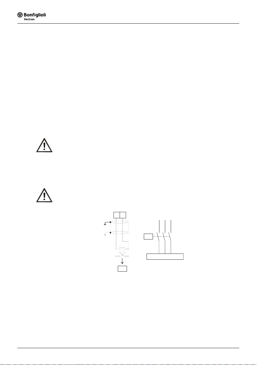
5.4.3.4 Group drive
For a group drive (several motors at one frequency inverter) the total length must be
shared in the number of motors according to the table values. A group drive with
synchronous servomotors is not possible.
Use a thermocouple for monitoring (for example PTC resistor) at each motor to avoid
damage.
5.4.3.5 Speed sensor connection
Install the speed sensor lines physically separate from the motor cables. Comply with
the manufacturer’s data of the speed sensor.
Install the shielding near to the frequency inverter and keep the speed sensor lines as
short as possible.
5.4.4 Connection of a Brake Resistor
The connection of a brake resistor is done via terminal X2.
Danger! Switch off power supply before connecting or disconnecting the brake
resistor cables. Dangerous voltage may be present at the motor terminals
and the terminals of the brake resistor even after the frequency inverter
has been disconnected safely from power supply. Wait for some minutes
until the DC link capacitors have discharged before starting to work at the
• The unit may only be connected with the power supply switched off.
• Make sure that the frequency inverter is discharged.
unit.
Caution! The brake resistor must be equipped with a temperature switch. The tem-
perature switch must disconnect the frequency inverter from mains supply
if the brake resistor is overloaded.
X2
Rb2Rb1
L1L2L3
K1
R
b
Rb1 Rb2
T1
Note: Keep the brake resistor lines as short as possible.
K1
Operating Instructions ACTIVE 06/0738
X1
T2

5.5 Connection of the construction sizes
5.5.1 ACT 201 (up to 3.0 kW) and ACT 401 (up to 4.0 kW)
The mains connection of the frequency inverter is done via plug-in terminal X1. The
connection of the motor and the brake resistor to the frequency inverter is done via
plug-in terminal X2. Degree of protection IP20 (EN60529) is only guaranteed if the
terminals are plugged in.
Danger! Switch off power supply before connecting or disconnecting the
• The unit may only be connected with the power supply switched off.
• Make sure that the frequency inverter is discharged.
Mains power connection ACT 201 (up to 3.0 kW) and
550 W … 1.1 kW
-
+
keyed plug-in terminals X1 and X2. Dangerous voltage may be present
at the mains terminals and the DC terminals even after the frequency
inverter has been disconnected safely from power supply. Wait for some
minutes until the DC link capacitors have discharged before starting the
work.
ACT 401 (up to 4.0 kW)
Phoenix ZEC 1,5 / .. ST7,5
X1
0.2 … 1.5 mm
AWG 24 … 16
0.2 … 1.5 mm
AWG 24 … 16
0.25 … 1.5 mm
AWG 22 … 16
0.25 … 1.5 mm
AWG 22 … 16
L2 L3L1
-
L1
L2 L3
+
+
2
2
2
2
-
L2 L3L1
L1
1ph / 230V AC
1.5 kW … 3.0 kW
- L1 L2 L3L1
+
L1 N PE
With a mains current above 10 A, the mains power connection 230 V 1ph/N/PE
1
and the mains power connection 230 V 2ph/N/PE are to be done on two terminals.
PE
N
Operating Instructions ACTIVE06/07 39
L1 L2 PE
2ph / 230V AC
1.5 kW … 3.0 kW 1.5 kW … 4.0 kW
L1 L2 L3L1
-
+
L1 L2 PE L1
2ph / 230V AC1ph / 23 0V AC
L1
L2
3ph / 230V AC
3ph / 400V AC
L1 L2 L3L1
-
+
3ph / 230V AC
3ph / 400V AC
L3 PE
L3
L2
PE

5
1
2
Motor power connection ACT 201 (up to 3.0 kW) and
ACT 401 (up to 4.0 kW)
Phoenix ZEC 1,5 / .. ST7,
X2
0.2 … 1.5 mm
AWG 24 … 16
0.2 … 1.5 mm
AWG 24 … 16
0.25 … 1.5 mm
AWG 22 … 16
0.25 … 1.5 mm
AWG 22 … 16
Rb2Rb1
V WU
2
2
2
2
U
Delta connection
Connection of brake resistor with temperature switch
VW
X2
U
Rb2Rb1
R
b
Rb1 Rb2
T
T
U
VW
Star connection
V W
X2
Phoenix ZEC 1,5 / .. ST7,5
M
3~
0.2 … 1.5 mm
AWG 24 … 16
0.2 … 1.5 mm
AWG 24 … 16
0.25 … 1.5 mm
AWG 22 … 16
0.25 … 1.5 mm
AWG 22 … 16
2
2
2
2
Operating Instructions ACTIVE 06/0740

5.5.2 ACT 201 (4.0 up to 9.2 kW) and ACT 401 (5.5 up to
8
Danger! Switch off power supply before connecting or disconnecting the
• The unit may only be connected with the power supply switched off.
• Make sure that the frequency inverter is discharged.
ACT 201-18 (4.0 kW): one- and three-phase connection is possible.
ACT 201-19 (5.5 kW) and above: three-phase connection is possible
15.0 kW)
Mains power connection ACT 201 (4.0 up to 9.2 kW) and
4.0 kW & 9.2 kW
6qmm / RM7,5
mains cable to terminal X1 and the motor cable and the brake resistor
to terminal X2. Dangerous voltage may be present at the mains terminals and the DC terminals even after the frequency inverter has been
disconnected safely from power supply. Wait for some minutes until the
DC link capacitors have discharged before starting the work.
ACT 401 (5.5 up to 15.0 kW)
X1
L2 L3L1
L1
L3 PE
L2
3ph / 230V AC
3ph / 400V AC
ACT 201-18 (4.0 kW):
X1
L2 L3L1
L1
N PE
1ph / 230V AC
11 kW & 15 kW
16qmm / RM10+15
0.2 & 16 mm
AWG 24 & 6
0.2 & 16 mm
AWG 24 & 6
0.25 & 10 mm
AWG 22 & 8
0.25 & 10 mm
AWG 22 &
-
+
-
+
2
2
2
2
0.2 & 6 mm
AWG 24 & 10
0.2 & 6 mm
AWG 24 & 10
0.25 & 4 mm
AWG 22 & 12
0.25 & 4 mm
AWG 22 & 16
X1
2
2
2
2
Operating Instructions ACTIVE06/07 41

6
2
8
2
X
8
Motor power connection ACT 201 (4.0 up to 9.2 kW) and
ACT 401 (5.5 up to 15.0 kW)
X2
Rb1
U
X2
VWU
VWU
3~
V W
M
Rb2
Delta connection
4.0 kW … 9.2 kW
6qmm / RM7,5
Connection of brake resistorwith temperature switch
Star connection
0.2 … 6 mm
AWG 24 … 10
0.2 … 6 mm
AWG 24 … 10
0.25 … 4 mm
AWG 22 … 12
0.25 … 4 mm
AWG 22 … 1
2
2
2
2
X2
4.0 kW … 9.2 kW
6qmm / RM7,5
0.2 … 6 mm
AWG 24 … 10
0.2 … 6 mm
AWG 24 … 10
0.25 … 4 mm
AWG 22 … 12
0.25 … 4 mm
AWG 22 … 16
2
2
2
2
11.0 kW … 15.0 kW
16qmm / RM10+15
2
V WU
Rb1 Rb2
11.0 kW … 15.0 kW
16qmm / RM10+15
0.2 … 16 mm
AWG 24 … 6
0.2 … 16 mm
AWG 24 … 6
0.25 … 10 mm
AWG 22 … 8
0.25 … 10 mm
AWG 22 …
0.2 … 16 mm
AWG 24 … 6
0.2 … 16 mm
AWG 24 … 6
0.25 … 10 mm
AWG 22 … 8
0.25 … 10 mm
AWG 22 …
Rb2Rb1
R
b
T1
2
2
T2
2
2
2
2
Operating Instructions ACTIVE 06/0742

F
4
5.5.3 ACT 401 (18.5 up to 30.0 kW)
Danger! Switch off power supply before connecting or disconnecting the
• The unit may only be connected with the power supply switched off.
• Make sure that the frequency inverter is discharged.
Mains power connection ACT 401 (18.5 up to 30.0 kW)
X1
L2 L3L1
L1
L2
3ph / 400V AC
mains cable to terminal X1 and the motor cable and the brake resistor
to terminal X2. Dangerous voltage may be present at the mains terminals and the DC terminals even after the frequency inverter has been
disconnected safely from power supply. Wait for some minutes until the
DC link capacitors have discharged before starting the work.
X1
18.5 kW … 30.0 kW
-
+
L3 PE
2.5 Nm
22.1 lb-in
PHOENIX MKDSP 25/ 6-1 5,00-
0.5 … 35 mm
AWG 20 … 2
0.5 … 25 mm
AWG 20 … 4
1.00 … 25 mm
AWG 18 … 4
1.5 … 25 mm
AWG 16 …
2
2
2
2
Operating Instructions ACTIVE06/07 43

X
X
2
Motor power connection ACT 401 (18.5 up to 30.0 kW)
18.5 kW … 30 kW
25/ 6-15,00
0.5 … 35 mm
AWG 20 … 2
0.5 … 25 mm
AWG 20 … 4
1.00 … 25 mm
AWG 18 … 4
1.5 … 25 mm
AWG 16 … 4
2
2
2
2
Connection of brake resistor with temperature switch
2
2.5 Nm
22.1 lb-in
VWU
Star connection
2
V W
M
3~
Rb1
U
VWU
Delta connection
Rb2
X2
V WU
Rb2Rb1
X2
R
b
Rb1 Rb
18.5 kW … 30 kW
25/ 6-15,00
0.5 … 35 mm
AWG 20 … 2
0.5 … 25 mm
AWG 20 … 4
1.00 … 25 mm
AWG 18 … 4
1.5 … 25 mm
AWG 16 … 4
2
2
2
2
2.5 Nm
22.1 lb-in
T1
T2
Operating Instructions ACTIVE 06/0744

5.5.4 ACT 401 (37.0 up to 65.0 kW)
Danger! Switch off power supply before connecting or disconnecting the
• The unit may only be connected with the power supply switched off.
• Make sure that the frequency inverter is discharged.
Mains power connection ACT 401 (37.0 up to 65.0 kW)
X1
L2 L3L1
L2
L1
L3 PE
3ph / 400V AC
mains cable to terminal X1 and the motor cable and the brake resistor
to terminal X2. Dangerous voltage may be present at the mains terminals and the DC terminals even after the frequency inverter has been
disconnected safely from power supply. Wait for some minutes until the
DC link capacitors have discharged before starting the work.
X1
37.0 kW … 65.0 kW
threaded bolt M8x25
-
+
70.8 lb-in
wire cross section up to 7 0 mm
8 Nm
2
Operating Instructions ACTIVE06/07 45

2
Motor power connection ACT 401 (37.0 up to 65.0 kW)
X2
Rb2Rb1
V WU
70.8 lb-in
M
3~
Connection of brake resistor with temperature switch
X2
37.0 kW … 65.0 kW
thre ade d bolt M8x 25
wire cross section up to 70 mm
8 Nm
VWU
Star conne ction
VWU
Delta c onnection
2
X2
X2
V WU
Rb2Rb1
R
b
Rb1 Rb2
T1
T
70.8 lb-in
37.0 kW … 65.0 kW
threaded bolt M8x25
Wire cross section up to 70 mm
8 Nm
2
Note: Optional, the inverters in this size can be purchased without brake
chopper. The terminals Rb1 and Rb2 are then not connected internally.
Operating Instructions ACTIVE 06/0746

5.5.5 ACT 401 (75.0 up to 132.0 kW)
Danger! Switch off power supply before connecting or disconnecting the
• The unit may only be connected with the power supply switched off.
• Make sure that the frequency inverter is discharged.
Mains power connection ACT 401 (75.0 up to 132.0 kW)
mains cable, motor cable and the brake resistor. Dangerous voltage may
be present at the mains terminals and the DC terminals even after the
frequency inverter has been disconnected safely from power supply.
Wait for some minutes until the DC link capacitors have discharged before starting the work.
U
VW
ZK+
Rb2
L1
L2
Threaded bolt M8x20
ZK-
L3
10 Nm
88.5 lb-in
L1
L2 L3
L2
L1
L3 PE
3ph / 400V AC
Operating Instructions ACTIVE06/07 47

Motor power connection ACT 401 (75.0 up to 132.0 kW)
10 Nm
88.5 lb-in
U
VW
ZK+
Rb2
L1
L2
VWU
Threaded bolt M8x20
Star connection
Connection of brake resistor with temperature switch
U
VW
ZK+
Rb2
ZK-
L3
VWU
Delta connection
10 Nm
88.5 lb-in
U
VW
M
3~
ZK+
Rb2
ZK-
L3
R
b
ZK+ Rb2
T1
T2
Threaded bolt M8x20
L1
L2
Note: Optional, the inverters in this size can be purchased without brake
chopper and are then not provided with the terminal Rb2 for a brake
resistor connection.
Operating Instructions ACTIVE 06/0748

The control and software functionality can be freely configured to ensure a reliable
5.6 Control Terminals
and economical operation. The operating instructions describe the factory settings of
the standard connections in the relevant
parameters to be set up.
Caution! Switch off power supply before connecting or disconnecting the keyed
Configuration 30 as well as the software
control inputs and outputs. Otherwise, components may be damaged.
• The unit may only be connected with the power supply switched off.
• Make sure that the frequency inverter is discharged.
Control Terminals
Wieland DST85 / RM3,5
0.2 … 0.3 Nm
1.8 … 2.7 lb-in
Control terminal X210A
0.14 … 1.5 mm
AWG 30 … 16
0.14 … 1.5 mm
AWG 30 … 16
0.25 … 1.0 mm
AWG 22 … 18
0.25 … 0.75 mm
AWG 22 … 20
2
2
2
2
Ter. Description
1 Voltage output 20 V, I
2 Ground / GND 20 V
3 Digital input S1IND, U
response time approx. 16ms (on), 10 μs (off)
4 Digital input EM-S2IND, U
response time approx. 16 ms
5 Digital input EM-S3IND, U
response time approx. 16 ms
6 Digital input S4IND, U
frequency signal: 0...30 V, 10 mA at 24 V, f
7 Digital input S5IND, U
frequency signal: 0...30 V, 10 mA at 24 V, f
=180 mA 1)
max
= DC 30 V, 10 mA at DC 24 V, PLC compatible,
max
= DC 30 V, 10 mA at DC 24 V, PLC compatible,
max
= DC 30 V, 10 mA at DC 24 V, PLC compatible,
max
= DC 30 V, 10 mA at DC 24 V, PLC compatible,
max
= DC 30 V, 10 mA at DC 24 V, PLC compatible,
max
= 150 kHz
max
= 150 kHz
max
Control terminal X210B
Ter. Description
1 Digital input S6IND, U
response time approx. 16 ms
=30 V, 10 mA at 24 V, PLC compatible,
max
2 Ground / GND 20 V
3 Digital output S1OUT, U= DC 24 V, I
4 Multi-function output MFO1,
analog signal: U= DC 24 V, I
digital signal: U= DC 24 V, I
frequency signal: DC 0...24 V, I
5 Reference output DC 10 V, I
6 Multi-function input MFI1,
max
max
max
=40 mA, overload and short-circuit proof
max
=40 mA, pulse-width modulated, f
=40 mA, overload and short-circuit proof,
=40 mA, f
max
=4 mA
=150 kHz
max
=116 Hz
PWM
analog signal: resolution 12 Bit, DC 0... 10 V (Ri=70 kΩ), 0...20 mA (Ri=500 Ω),
digital signal: response time approx. 16 ms, U
PLC compatible
7 Ground / GND 10 V
1)
The power supply at terminal X210A.1 may be loaded with a maximum current of
= 180 mA. The maximum current available is reduced by the digital output
I
max
S1OUT and multifunctional output MFO1.
= DC 30 V, 4 mA at DC 24 V,
max
Operating Instructions ACTIVE06/07 49

A
By default, the freely programmable relay output is linked to the monitoring function
5.6.1 Relay Output
(factory setting). The logic link to various functions can be freely configured via the
software parameters. Connection of the relay output is not absolutely necessary for
the function of the frequency inverter.
Relay Output
X10
X10
1
2
3
S3OUT
Control terminal X10
Phoenix ZEC 1,5/3ST5,0
0.2 … 1.5 mm
AWG 24 … 16
0.2 … 1.5 mm
AWG 24 … 16
0.25 … 1.5 mm
AWG 22 … 16
0.25 … 1.5 mm
WG 22 … 16
2
2
2
2
Ter. Description
1 .. 3 Relay output, floating change-over contact, min. 50 000 switching operations,
response time approx. 40 ms,
max. contact load, make contact AC 5 A / 240 V, DC 5 A (ohmic) / 24 V
max. contact load, break contact AC 3 A / 240 V, DC 1 A (ohmic) / 24 V
Operating Instructions ACTIVE 06/0750

The control hardware and the software of the frequency inverter are freely configur-
Thanks to the modular design, the frequency inverter can be adapted to a great
5.6.2 Control Terminals – Terminal Diagram
able to a great extent. Certain functions can be assigned to the control terminals, and
the internal logic of the software modules can be freely selected.
range of different driving tasks.
The demands made of the control hardware and software are well known in the case
of standard driving tasks. This control terminal logic and internal function assignments of the software modules are available in standard configurations. These assignments can be selected via parameter
Configuration 110 contains the functions for variable-speed control of a 3-phase ma-
configurations, please contact us.
5.6.2.1 Configuration 110 – Sensorless Control
Configuration 30. For information on other
chine in a wide range of standard applications. The motor speed is set according to
X210A.1 Supply voltage +20 V
X210A.2 Ground 20 V
X210A.3 Controller release / error acknowl-
X210A.4 Start of clockwise operation
X210A.5 Start of anticlockwise operation
X210A.6 Data set change-over 1
X210A.7 Data set change-over 2
X210B.1 Motor thermal contact
X210B.2 Ground 20 V
X210B.3 Operating message
X210B.4 Analog signal of actual frequency
X210B.5 Supply voltage +10 V
the selected ratio of the reference frequency to the necessary voltage.
X210A
1
+20 V/180 mA
GND 20 V
2
3
S1IND
S2IND
4
5
S3IND
6
S4IND
7
M
S5IND
Control terminal X210A
edgment
X210B
S6IND
1
GND 20 V
-
2
+
V
+
S1OUT
3
MFO1A
4
+10 V/ 4 mA
5
MFI1A
6
GND 10 V
7
Control terminal X210B
Reference value potentiometer
X210B.6 Reference speed 0 ...+10 V
X210B.7 Ground 10 V
Operating Instructions ACTIVE06/07 51

5.6.2.2 Configuration 111 – Sensorless Control with Technol-
M
-
+
-
+
-
M
-
+
-
ogy Controller
X210A
1
+20 V/180 mA
GND 20 V
2
3
S1IND
S2IND
4
5
S3IND
6
S4IND
7
S5IND
X210B
S6IND
1
GND 20 V
2
S1OUT
3
+
MFO1A
V
4
+10 V/4 mA
5
MFI1A
6
GND 10 V
7
trol
X210A
1
+20 V/180 mA
GND 20 V
2
3
S1IND
S2IND
4
5
S3IND
6
S4IND
7
S5IND
X210B
S6IND
1
GND 20 V
2
S1OUT
3
+
MFO1A
V
4
+10 V/4 mA
5
MFI1A
6
GND 10 V
7
Control terminal X210A
edgment
over 1
over 2
Control terminal X210B
X210B.7 Ground 10 V
Control terminal X210A
edgment
Control terminal X210B
Reference value potentiometer
X210B.7 Ground 10 V
Configuration 111 extends the functionality of the sensorless control by software func-
tions for easier adaptation to the customer's requirements in different applications.
The Technology Controller enables flow rate, pressure, level or speed control.
X210A.1 Supply voltage +20 V
X210A.2 Ground 20 V
X210A.3 Controller release / error acknowl-
X210A.4 Fixed percentage value change-
X210A.5 Fixed percentage value change-
X210A.6 Data set change-over 1
X210A.7 Data set change-over 2
X210B.1 Motor thermal contact
X210B.2 Ground 20 V
X210B.3 Operating message
X210B.4 Analog signal of actual frequency
X210B.5 Supply voltage +10 V
X210B.6 Actual percentage value 0 ...+10 V
Configuration 410 contains the functions for sensorless, field-oriented control of a 3-
5.6.2.3 Configuration 410 – Sensorless Field-Oriented Con-
phase machine. The current motor speed is determined from the present currents and
voltages in combination with the machine parameters. Separate control of torque and
flux-forming current enables a high drive dynamics at a high load moment.
X210A.1 Supply voltage +20 V
X210A.2 Ground 20 V
X210A.3 Controller release / error acknowl-
X210A.4 Start of clockwise operation
X210A.5 Start of anticlockwise operation
X210A.6 Data set change-over 1
X210A.7 Data set change-over 2
X210B.1 Motor thermal contact
X210B.2 Ground 20 V
X210B.3 Operating message
X210B.4 Analog signal of actual frequency
X210B.5 Supply voltage +10 V
X210B.6 Reference speed 0 ...+10 V
Operating Instructions ACTIVE 06/0752

Configuration 411 extends the functionality of the sensor-less field-oriented control of
Configuration 410 by a Technology Controller. The Technology Controller enables a
control based on parameters such as flow rate, pressure, filling level or speed.
M
5.6.2.5 Configuration 430 – Sensorless Field-Oriented Con-
Configuration 430 extends the functionality of the sensor-less field-oriented control of
Configuration 410 by a Torque Controller. The reference torque is represented as a
percentage and it is transmitted into the corresponding operational performance of
the application. Change-over between variable-speed control and torque-dependent
control is done via a digital control input.
M
trol with Technology Controller
-
+
V
+
-
trol, speed or torque controlled
-
+
V
5.6.2.4 Configuration 411 – Sensorless Field-Oriented Con-
X210A
X210B
+
X210A
X210B
+
1
2
3
4
5
6
7
1
2
3
4
5
6
7
1
2
3
4
5
6
7
1
2
3
4
5
6
7
+20 V/180 mA
GND 20 V
S1IND
S2IND
S3IND
S4IND
S5IND
S6IND
GND 20 V
S1OUT
MFO1A
+10 V/4 mA
MFI1A
GND 10 V
+20 V/180 mA
GND 20 V
S1IND
S2IND
S3IND
S4IND
S5IND
S6IND
GND 20 V
S1OUT
MFO1A
+10 V/4 mA
MFI1A
GND 10 V
X210A.1 Supply voltage +20 V
Control terminal X210A
X210A.2 Ground 20 V
X210A.3 Controller release / error acknowl-
edgment
X210A.4 Fixed percentage value change-
over 1
X210A.5 no function assigned
X210A.6 Data set change-over 1
X210A.7 Data set change-over 2
Control terminal X210B
X210B.1 Motor thermal contact
X210B.2 Ground 20 V
X210B.3 Operating message
X210B.4 Analog signal of actual frequency
X210B.5 Supply voltage +10 V
X210B.6 Actual percentage value 0 ...+10 V
X210B.7 Ground 10 V
Control terminal X210A
X210A.1 Supply voltage +20 V
X210A.2 Ground 20 V
X210A.3 Controller release / error acknowl-
edgment
X210A.4 Start of clockwise operation
X210A.5 n-/T change-over control function
X210A.6 Data set change-over 1
X210A.7 Data set change-over 2
Control terminal X210B
X210B.1 Motor thermal contact
X210B.2 Ground 20 V
X210B.3 Operating message
X210B.4 Analog signal of actual frequency
X210B.5 Supply voltage +10 V
Reference value potentiometer
X210B.6 Reference speed 0 ...+10 V
X210B.7 Ground 10 V
Operating Instructions ACTIVE06/07 53

A
Configuration 210 contains the functions for speed-controlled, field-oriented control of
5.6.2.6 Configuration 210 – Field-Oriented Control, speed
controlled
a 3-phase machine with speed sensor feedback. The separate control of torque and
flux-forming current enables high drive dynamics with a high load moment. The nec-
X210A.1 Supply voltage +20 V
X210A.2 Ground 20 V
X210A.3 Controller release / error acknowl-
X210A.4 Start of clockwise operation
X210A.5 Start of anticlockwise operation
X210A.6 Speed sensor track B
X210A.7 Speed sensor track A
X210B.1 Motor thermal contact
X210B.2 Ground 20 V
X210B.3 Operating message
X210B.4 Analog signal of actual frequency
X210B.5 Supply voltage +10 V
essary speed sensor feedback results in a precise speed and torque performance.
X210A
1
+20 V/180 mA
GND 20 V
2
3
S1IND
S2IND
4
5
-
+
S3IND
B
6
S4IND
A
7
S5IND
Control terminal X210A
edgment
M
X210B
S6IND
1
GND 20 V
-
2
+
V
+
S1OUT
3
MFO1A
4
+10 V/4 mA
5
MFI1A
6
GND 10 V
7
Control terminal X210B
Reference value potentiometer
X210B.6 Reference speed 0 ...+10 V
5.6.2.7 Configuration 211 – Field-Oriented Control, with
Technology Controller
Configuration 211 extends the functionality of the speed-controlled, field-oriented
X210B.7 Ground 10 V
control of Configuration 210 by a Technology Controller. The Technology Controller
enables a control based on parameters such as flow rate, pressure, filling level or
X210A.1 Supply voltage +20 V
X210A.2 Ground 20 V
X210A.3 Controller release / error acknowl-
X210A.4 Fixed percentage value change-
X210A.5 no function assigned
X210A.6 Speed sensor track B
X210A.7 Speed sensor track A
X210B.1 Motor thermal contact
X210B.2 Ground 20 V
X210B.3 Operating message
X210B.4 Analog signal of actual frequency
speed.
+
M
X210A
1
+20 V/180 m
GND 20 V
2
3
S1IND
S2IND
4
5
-
S3IND
B
6
S4IND
A
7
S5IND
Control terminal X210A
edgment
over 1
X210B
S6IND
1
GND 20 V
-
2
+
-
+
-
V
+
S1OUT
3
MFO1A
4
+10 V/4 mA
5
MFI1A
6
GND 10 V
7
Control terminal X210B
X210B.5 Supply voltage +10 V
X210B.6 Actual percentage value 0 ...+10 V
X210B.7 Ground 10 V
Operating Instructions ACTIVE 06/0754

Configuration 230 extends the functionality of Configuration 210 by functions for
5.6.2.8 Configuration 230 – Field-Oriented Control, speed
and torque controlled
torque-dependent, field-oriented control. The reference torque is represented as a
percentage and it is transmitted into the corresponding operational performance of
the application. Change-over between variable-speed control and torque-dependent
X210A.1 Supply voltage +20 V
X210A.2 Ground 20 V
X210A.3 Controller release / error acknowl-
X210A.4 Start of clockwise operation
X210A.5 n-/T change-over control function
X210A.6 Speed sensor track B
X210A.7 Speed sensor track A
X210B.1 Motor thermal contact
X210B.2 Ground 20 V
X210B.3 Operating message
X210B.4 Analog signal of actual frequency
X210B.5 Supply voltage +10 V
control is done via a digital control input.
X210A
1
+20 V/180 mA
GND 20 V
2
3
S1IND
S2IND
4
5
-
+
S3IND
B
6
S4IND
A
7
S5IND
M
X210B
S6IND
1
GND 20 V
-
2
+
V
+
S1OUT
3
MFO1A
4
+10 V/4 mA
5
MFI1A
6
GND 10 V
7
Control terminal X210A
edgment
Control terminal X210B
Reference value potentiometer
X210B.6 Reference speed 0 ...+10 V
X210B.7 Ground 10 V
Operating Instructions ACTIVE06/07 55

A
The optional KP500 control unit is a practical tool for controlling the frequency inverter
6 Control Unit KP500
and setting and displaying the frequency inverter parameters.
The control unit is not absolutely necessary for the operation of the frequency inverter
and can be plugged on when required.
B
C
F
E
D
H
G
I
RUN Used for starting the drive and opening the CTRL menu.
A
J
Keys
Press the RUN key to open the motor potentiometer function.
STOP Used for opening the CTRL menu, stopping the drive and acknowledging
faults.
J
Used for navigating in the menu structure and selecting parameters.
▲ ▼
Used for increasing/decreasing parameter values.
ENT Accessing parameters or changing the menu within the menu structure.
Confirmation of the selected function or the set parameter.
ESC Used for aborting parameters or switching back to the previous menu within
the menu structure. Canceling the function or resetting the parameter value.
FUN Used for switching over the key function, access to special functions.
VAL Display actual values.
Three-digit 7-segment display to show the parameter number.
B
One-digit 7-segment display for display of the active data record, direction of rota-
C
tion etc.
Display of the selected menu branch:
D
Display
PARA Select parameters and adjust parameter values.
CTRL Select a function for adjustment and/or display via the control unit:
SEtUP guided commissioning.
CtrL motor potentiometer and jog function.
CPY Copy parameters via the control unit:
ALL All the parameter values are copied.
Act Only the active parameter values are copied.
FOr Control unit memory is formatted and deleted.
WARN Warning about a critical operating behavior.
Status and operating messages:
E
FAULT Message indicating that the unit was switched off due to a fault.
RUN Flashing: signals readiness for operation.
Lights up: signals that the unit is operating and the output stage is enabled.
REM Active remote control via interface connection.
F Function switch-over with the FUN key.
Five-digit 7-segment display for display of parameter value and sign.
F
Physical unit of the parameter value displayed.
G
Active acceleration or deceleration ramp.
H
Current direction of rotation of the drive.
I
Operating Instructions ACTIVE 06/0756

The menu structure of the control unit is arranged as shown in the following illustra-
6.1 Menu Structure
tion. In the optionally available PC user software VPlus, the functions and parameters
are structured in various levels depending on their function. The software contains the
full set of information and enables a flexible use of the parameter setting and control
options.
6.2 Main Menu
The various parameters and information of the frequency inverter can be displayed by
means of the control unit. The different functions and parameters are grouped together in four menu branches. From any point in the menu structure you can return
to the main menu by pressing the ESC key either continuously or repeatedly.
Note: In the following description of the key functions, a plus (+) between the
key symbols indicates that the keys have to be pressed at the same time.
A comma (,) between the key symbols indicates that the keys have to be
pressed one after the other.
Menu branch VAL
Display of actual values
Menu branch PARA
Display and edit parameters
Menu branch CPY
Copy parameters
Menu branch CTRL
Select control and test functions
Use the arrow keys to select the required menu branch. The selected menu branch is
displayed (flashing).
Select the menu branch by pressing the ENT key. The first parameter or the first function in the selected menu branch will be displayed.
Press the ESC key to return to the main menu of the control unit.
▲ ▼
Navigate through the menu structure and select a menu branch.
Keys
ENT Open the selected menu branch.
ESC Cancel the current menu branch and return to the main menu.
Operating Instructions ACTIVE06/07 57

In the VAL menu branch, the control unit displays a variety of actual values, depend-
6.3 Actual Value Menu (VAL)
ing on the configuration selected and the options installed. The parameters and basic
software functions linked to the corresponding actual value are documented in the
operating instructions.
ESC
E
A
Use the arrow keys to select the required number from the actual values dis-
A
played in numerical order.
ENT
B
C
ENT
D
ESC
In the current record, the record-related actual value parameters are displayed,
including the corresponding data record number. The seven-segment display
shows data record 0 if the actual values in the four data sets are identical.
▲ + ▼
FUN , ▲
FUN , ▼
Use the ENT key to select the parameter. The parameter is displayed including
B
its current value, unit and the active data record.
During commissioning, operation and error analysis, it is possible to monitor
C
each actual value parameter specifically.
Display the actual value parameter upon switch-on.
Display last actual value parameter (highest number).
Display first actual value parameter (lowest number).
Keys
Some of the actual value parameters are arranged in the four available data
records. If the parameter values in the four data records are identical, the actual
value is displayed in data record 0. If the actual values in the four data records
are different, diFF is displayed in data record 0.
▲ , ▼
Switch to another of the data set in the case of related actual
Keys
values.
FUN , ▲
FUN , ▼
Determine minimum value and display it permanently.
Determine maximum value and display it permanently.
FUN , ENT Display of mean value of the actual value during the
Use the ENT key to save the selected actual value as a parameter displayed at
D
switch-on. The message SEt (with parameter number) is displayed for a short
monitoring period.
time. When the frequency inverter is switched on the next time, this actual value
will be displayed automatically.
After saving the parameter, you can monitor and display the value again. Use
E
the ESC key to switch to the parameter selection of the VAL menu branch.
Operating Instructions ACTIVE 06/0758

The parameters to be configured during the guided commissioning were selected from
6.4 Parameter Menu (PARA)
common applications and can be supplemented as required by further settings in the
PARA menu branch. The parameters and basic software functions linked to the corresponding actual value are documented in the operating instructions.
E
A
Use the arrow keys to select the required number from the parameters displayed
A
in numerical order. The parameter number is displayed with the active data set
ENT
B
C
ENT
D
ESC
(flashes).
In the current data set, the related parameters are displayed, including the corresponding data set number. The seven-segment display shows data set 0 if the
parameter values in the four data sets are identical.
▲ + ▼
FUN , ▲
FUN , ▼
Use the ENT key to select the parameter. The parameter is displayed including
B
its value, unit and the active data set. If settings are edited in data set 0, the
Change to the last parameter edited.
Display of last parameter (highest number).
Display of first parameter (lowest number).
Keys
parameter values are changed in the four data sets.
Use the arrow keys to adjust the parameter value or to select an operation
C
mode. The adjustment possibilities you have depend on the parameter.
Keep the arrow keys pressed for a while to change the displayed values quickly.
If you release the keys again, the speed at which the values change is reduced
again.
If the parameter value starts to flash, the speed at which the values change is
reset to the initial value again.
FUN , ENT Change of the data set in the case of data set related parameters.
▲ + ▼
FUN , ▲
FUN , ▼
Use the ENT key to save the parameter. For a short time, the message SEt in-
D
cluding the parameter number and the data set is displayed. To leave the parameter unchanged, press the ESC key.
Set parameter to factory setting.
Set parameter to highest value.
Set parameter to smallest value.
Keys
Messages
Err1: EEPrO Parameter has not been saved.
Err2: StOP Parameter can only be read (i.e. not edited) when the unit is in
operation.
Err3: Error Other error.
After saving the parameter, you can edit the value again or return to the pa-
E
rameter selection menu by pressing the ESC key.
Operating Instructions ACTIVE06/07 59

With the copy function of the control unit you can copy the parameter values from the
6.5 Copy Menu (CPY)
frequency inverter to a non-volatile memory of the control unit (upload) and store
(download) them to a frequency inverter again.
The copy function makes the parameterization of recurring applications much easier.
The function archives all parameter values, regardless of access control and value
range. The memory space available in the control unit for the files is dynamically
scaled to match the scope of the data.
Note: The Copy Menu (CPY) is accessible in control level 3. The control level
6.5.1 Reading the Stored Information
can be adjusted, if necessary, via parameter
Control Level 28.
When you open the CPY menu branch, the data stored in the
control unit are read out. This process takes a few seconds.
During this time, init and a progress indicator are displayed.
After the initialization in the copy menu, the function can be
selected.
If the information stored in the control unit is not valid, the
initialization is stopped and an error message is displayed.
In this case, the memory in the control unit must be formatted
as follows:
• Use the ENT key to confirm the error message.
• Use the arrow keys to select the function FOr.
• Use the ENT key to confirm the selection.
During the formatting operation, FCOPY and a progress
The process takes a few seconds. When the process is
• Confirm the message by pressing the ENT key.
indicator are displayed.
complete, the message rdY is displayed.
Now, you can select the copy function as described in the fol-
lowing.
Operating Instructions ACTIVE 06/0760

The copy menu CPY contains three main functions. Use the arrow keys to select the
6.5.2 Menu Structure
required function. Select the source and the destination for the process. The memory
space available in the non-volatile memory of the control unit is displayed on the
three-digit seven-segment display as a percentage value.
Function – FOr
Use the function FOr to format and delete the memory in the
control unit. This may be necessary if a new control unit is
used for the first time.
Function – ALL
All readable and writable parameter values are transferred.
• Confirm this selection by pressing the ENT key and con-
tinue by selecting the source.
Function – Act
Only the active parameter values of the frequency inverter are
copied to the control unit. The number of active parameter
values depends on the current selected configuration of the
frequency inverter.
When data are copied from the control unit to the frequency
inverter, all parameter values stored are transferred, like in the
case of the ALL function.
• Confirm the selection Act by pressing the ENT key and
The parameters of the ALL and Act sub-functions in the CPY menu branch can be
continue by selecting the source.
6.5.3 Selecting the Source
parameterized to meet the requirements of the specific application.
The available memory space of the control unit is shown on the seven-segment
display.
• Use the arrow keys to select the data source (Src.) for the copy operation (up-
load). You can use either the data sets of the frequency inverter (Src. x) or the
files of the control unit (Src. Fy) as the data source.
• Confirm the selected data source by pressing the ENT key and continue by select-
ing the destination.
Display Description
Src. 0 The data of the four data records of the frequency inverter are copied.
Src. 1 The data of data record 1 of the frequency inverter are copied.
Src. 2 The data of data record 2 of the frequency inverter are copied.
Src. 3 The data of data record 3 of the frequency inverter are copied.
Src. 4 The data of data record 4 of the frequency inverter are copied.
Src. E An empty data record for deletion of a file in the control unit.
Src. F1 File 1 is transferred from the memory of the control unit. 1)
Src. F2 File 2 is transferred from the memory of the control unit. 1)
Src. F3 File 3 is transferred from the memory of the control unit. 1)
Src. F4 File 4 is transferred from the memory of the control unit. 1)
Src. F5 File 5 is transferred from the memory of the control unit. 1)
Src. F6 File 6 is transferred from the memory of the control unit. 1)
Src. F7 File 7 is transferred from the memory of the control unit. 1)
Src. F8 File 8 is transferred from the memory of the control unit. 1)
1)
Empty files which are not filled with data yet cannot be used as signal sources. The
control unit memory is managed dynamically (see Chapter “Copy Menu (CPY)”)
Operating Instructions ACTIVE06/07 61

Select the destination (dSt.) of the copy operation (application-specific). The data
6.5.4 Selecting the Destination
source is transferred to the selected target (download).
• Use the arrow keys to select the destination (dSt.) for the copied data
(download). Depending on the data source selected, either the data records of the
frequency inverter (dSt. x) or empty files of the control unit (dSt. F y) can be used
as the target.
• Confirm the selection by pressing the ENT key. The copy process is started and
COPY is displayed.
Display Description
dSt. 0 The four data records of the frequency inverter are overwritten.
dSt. 1 The data are copied to data record 1 of the frequency inverter.
dSt. 2 The data are copied to data record 2 of the frequency inverter.
dSt. 3 The data are copied to data record 3 of the frequency inverter.
dSt. 4 The data are copied to data record 4 of the frequency inverter.
dSt. F1 The data are copied to file 1 of the control unit. 1)
dSt. F2 The data are copied to file 2 of the control unit. 1)
dSt. F3 The data are copied to file 3 of the control unit. 1)
dSt. F4 The data are copied to file 4 of the control unit. 1)
dSt. F5 The data are copied to file 5 of the control unit. 1)
dSt. F6 The data are copied to file 6 of the control unit. 1)
dSt. F7 The data are copied to file 7 of the control unit. 1)
dSt. F8 The data are copied to file 8 of the control unit. 1)
1)
Already existing files are not offered as possible targets.
6.5.5 Copy Operation
Attention! Before the parameter settings are transferred to the frequency inverter,
the individual parameter values are checked.
The value range and the parameter settings can differ according to the
power range of the frequency inverter. If parameter values are outside
of the value range, an error message will be displayed.
While the copy operation is in process, the message COPY
and, as a progress indicator, the number of the currently copied parameter will be displayed.
In the case of the Act function, the active parameter values
are copied only. Using the ALL function, parameters which are
not relevant to the selected configuration are copied, too.
Depending on the selected copy function (ALL or Act), the
copy operation is completed after some 100 seconds and the
display reads rdY.
Press the ENT key to switch to the copy menu. Use the ESC
key to switch to the target selection menu.
If the ESC key is pressed during the copy operation, the copy
operation is aborted before the transmission of the data is
complete. The message Abr and the number of the last parameter which was copied are displayed.
Press the ENT key to return to the selection in the copy menu.
Use the ESC key to switch to the target selection menu.
Operating Instructions ACTIVE 06/0762

6.5.6 Error Messages
The copy function archives all parameters, regardless of the
access control and the value range. Some of the parameters
are only writable if the frequency inverter is not in operation.
The controller input (S1IND) may not be activated during the
copy operation, otherwise the data transmission is aborted.
The message S1Ind and the number of the last parameter
which was copied are displayed. If the controller enable input
is deactivated again, the aborted copy operation is continued.
The data transmission from the selected source to the destina-
tion is continuously monitored by the copy function. If an error
occurs, the copy operation is aborted and the message Err
and an error code are displayed.
Error Messages
Code Meaning
1 Write error in memory of control unit;
0
repeat the copy operation. If error message is displayed again, format
the memory.
2 Read error in memory of control unit;
repeat the copy operation. If error message is displayed again, format
the memory.
3 The size of the memory of the control unit was not determined cor-
rectly.
If this error occurs repeatedly, replace the control unit.
4 Not enough memory; the data are incomplete.
Delete the incomplete file and date no longer needed from the control
unit.
5 The communication has been disturbed or interrupted;
repeat the copy operation, delete the incomplete file if necessary.
0 Invalid identification of a file in the control unit;
1
delete faulty file and format memory if necessary.
2 The memory space of the selected target file is occupied;
delete file or use different target file in the control unit.
3 The source file to be read in the control unit is empty;
only files containing reasonable data should be selected as a source.
4 Defective file in control unit;
delete faulty file and format memory, if necessary.
2 0 The memory in the control unit is not formatted;
format the memory via the FOr function in the copy menu.
0 Error during reading of a parameter from the frequency inverter;
3
check connection between the control unit and the frequency inverter
and repeat reading operation.
1 Error during writing of a parameter in the frequency inverter;
Check connection between the control unit and the frequency inverter
and repeat the writing operation.
2 Unknown parameter type;
delete faulty file and format memory if necessary.
4 0 The communication has been disturbed or interrupted;
repeat the copy operation, delete the incomplete file if necessary.
Operating Instructions ACTIVE06/07 63

The Parameter transfer operation mode enables the transmission of data from the
Activation of the KP 500 control unit for Parameter transfer mode is prepared via the
6.6 Read data from the KP 500 control unit
KP 500 control unit to the frequency inverter. In this operation mode, all functions of
the control unit are disabled except for the COPY function. Data transmission from the
frequency inverter to the control unit is also disabled.
parameter
nected to the frequency inverter.
Program(ming) 34. For this purpose, the KP 500 control unit must be con-
Program(ming) 34 Function
The KP 500 control unit is prepared for parameter
111 - Parameter transfer
transmission. A connected frequency inverter can receive data from the control unit.
110 - Normal mode Reset the KP 500 control unit to standard mode.
Attention! The KP 500 control unit can be activated for Parameter transfer only if
at least one file is stored in the control unit. Otherwise, the error mes-
The KP 500 control unit can be configured both via the keys of the KP 500 and via any
6.6.1 Activating
sage "F0A10" will be displayed.
other available CM communication module. To configure and activate the KP 500 con-
Activation via keyboard of the control unit
• Use the arrow keys to enter the value 111 – Parameter transfer and confirm your
trol unit, proceed as follows:
• In the parameter menu PARA, use the arrow keys to select parameter
gram(ming)
34 and confirm the selection by pressing the ENT key.
Pro-
selection by pressing the ENT key.
Before data can be transferred, the control unit must be initialized.
• Disconnect the control unit from the frequency inverter and re-connect it to the
Now, the control unit is ready for activation.
same or another frequency inverter.
The initialization operation is started. During the initialization, init and a progress
indicator are displayed. After the initialization, the KP 500 control unit is ready for
Note:
transferring data to the frequency inverter.
Setting the parameter
Program(ing) 34 to 111 – Parameter transfer
can be undone by means of the control unit, provided that the control
unit has not been initialized yet.
Program(ing) 34, use the arrow keys to enter the
• In parameter
value 110 – Normal Mode and confirm by pressing the ENT key.
Operating Instructions ACTIVE 06/0764

Activation via CM Communication Module
Attention! Activation of the control unit via a communication connection is only
possible if the frequency inverter is equipped with an optional CM communication module and the communication is effected via this module.
For this purpose, the control unit must be connected to the frequency
• Establish a communication connection to the frequency inverter.
• Start the communication and select parameter Program(ing) 34 via the commu-
nication interface.
• Via the communication interface, enter and confirm the value 111 in parameter
Program(ing)
• Via the communication interface, enter and confirm the value 123 in parameter
Program(ing)
inverter.
34.
34.
Frequency inverter is initialized again. The display of the control unit reads
"rESEt". Then, the initialization operation is started.
6.6.2 Transfer data
In order to transmit a file from the control unit to the frequency inverter, proceed as
follows:
• Connect the KP 500 control unit to the frequency inverter.
After the initialization, the data sources which are available for download are dis-
• Use the arrow keys to select the data source (Src.F.y) for the copy operation from
played.
the control unit to the frequency inverter.
Note: The files stored in the control unit contain all information and pa-
The files stored in the control unit can be used as data sources.
rameters stored in the control unit according to the selected copy
• Confirm the selection by pressing the ENT key.
function ALL or Act (see Chapter “Copy Menu (CPY)”).
The copy operation is started. The message COPY and the number of the currently processed parameter will be displayed to indicate the progress of the opera-
After the copy operation is complete, the control unit is initialized again.
tion.
Operating Instructions ACTIVE06/07 65

6.6.3 Reset to Normal Mode
A KP 500 control unit which was activated as a Download Keypad can be reset to
standard operation mode with full functionality via a special key sequence on the control unit or via any available CM communication module.
Resetting at control unit
• Press the control unit keys RUN and STOP at the same time for about 1 second.
The display shows – – – – – . Subsequent the topmost operation level of the
control unit display is available.
• In the parameter menu PARA, use the arrow keys to select parameter
gram(ming)
34 and confirm the selection by pressing the ENT key.
Pro-
• Use the arrow keys to enter the value 110 – Normal Mode and confirm your se-
lection by pressing the ENT key.
• Disconnect the control unit from the frequency inverter and re-connect it.
After the initialization, the control unit is ready for operation with its full function-
Attention! Resetting the control unit via a communication connection is only possi-
ality.
Resetting via CM communication module and/or control software VPlus
ble if the frequency inverter is equipped with an optional CM communi-
• Establish a communication connection to the frequency inverter.
• Start the communication and select parameter Program(ing) 34 via the commu-
nication connection.
• Via the communication connection, enter and confirm the value 110 in parameter
Program(ing)
• Via the communication connection, enter and confirm the value 123 in parameter
Program(ing)
cation module and the communication is effected via this module.
34.
34.
The frequency inverter is reset. The display of the control unit reads "rESEt".
After reset, the control unit is ready for operation with its full functionality.
6.7 Control Menu (CTRL)
Note: In order to be able to control the drive via the control unit, the digital
controller input S1IND must be connected and set to "High-Signal" in
order to enable the output stage.
Warning! • Switch off power supply before connecting and disconnecting control
terminal S1IND.
• The unit may only be connected with the power supply switched off.
• Make sure that the frequency inverter is discharged.
• When the frequency inverter is disconnected from power supply, the
mains, DC-link voltage and motor terminals may still be live for
some time. Wait for some minutes until the DC link capacitors have
discharged before starting to work at the unit.
Operating Instructions ACTIVE 06/0766

The frequency inverters can be controlled by means of the control unit and/or a com-
munication module. In the CTRL menu branch, various functions are available which
If you want to control the frequency inverter via an optional communication module,
make commissioning easier and enable the control of the inverter via the control unit.
the necessary adjustments can be made via parameter
Local/Remote 412. Via this
parameter, you can specify which functions will be available to the controller. Depending on the operation mode selected, only some of the control menu functions are
available. Refer to Chapter “Bus controller” for a detailed description of the parameter
Local/Remote 412.
6.8 Controlling the Motor via the Control Unit
The control unit enables controlling the connected motor in accordance with the se-
lected operation mode of parameter
Local/Remote 412.
Note: In order to be able to control the drive via the control unit, the digital
controller input S1IND (controller release) must be connected and set to
"High-Signal" in order to enable the output stage.
Warning! • Switch off power supply before connecting and disconnecting control
terminal S1IND.
• The unit may only be connected with the power supply switched off.
• Make sure that the frequency inverter is discharged.
• When the frequency inverter is disconnected from power supply, the
mains, DC-link voltage and motor terminals may still be live for
some time. Wait for some minutes until the DC link capacitors have
discharged before starting to work at the unit.
: When the RUN key was pressed, the drive was in operation already.
Operating Instructions ACTIVE06/07 67

for the function
The CTRL menu branch can be accessed via the navigation
within the menu structure. The CtrL function contains subfunctions which are displayed according to the operating point
of the frequency inverter.
Press the RUN key anywhere within the menu structure to
access the motor potentiometer function Pot
F. for clockwise
operation or Potr for anti-clockwise operation directly.
If the drive is running already, the display reads int
F (foward,
clockwise operation) / intr (reverse, anti-clockwise operation)
for the function internal reference value or inP
clockwise operation) / inPr (reverse, anti-clockwise operation)
F (forward,
"Motorpoti (KP)".
The function Motorpoti (KP) enables a link to other reference
value sources in the frequency reference value channel. The
function is described in Chapter “Motorpoti (KP)”.
Motor potentiometer function Pot
Use the arrow keys to adjust the output frequency of the frequency inverter from the
minimum frequency 418 to the
maximum frequency 419. The acceleration corresponds to the
factory settings (2 Hz/s) for parameter
Motorpoti
and
of low acceleration values.
473. The parameters Acceleration (Clockwise) 420
Deceleration (Clockwise) 421 are considered in the case
Function Motorpoti (KP) inP
Use the arrow keys to adjust the output frequency of the frequency inverter from the
Minimum Frequency 418 to the
Ramp Keypad-
Maximum Frequency 419. The adjusted frequency value by
means of the control unit can be connected with further reference values via
chapter “Frequency Reference Channel” and "Motorpoti (KP)".)
Internal reference value int
The drive is in operation, i.e. output signals are present at the
frequency inverter and the current actual value is displayed.
Press an arrow key to switch to the motor potentiometer function Pot. The current frequency value is taken over in the motor potentiometer function Pot.
JOG frequency JOG
This function is useful for manual setup and positioning of a
machine. The frequency of the output signal is set to the entered value if the FUN key is pressed.
• Press FUN key to switch from the internal reference value
int or the motor potentiometer function Pot to the parameter
• Keep the FUN key pressed and press the arrow keys to
adjust the required frequency.
• (The frequency value last adjusted is saved as the
frequency
• Release the FUN key to stop the drive.
• (The display returns to the previous function Pot or int or
to inP if function "Motorpoti (KP)" is active.)
Reference Frequency Source 475. (Refer to
JOG frequency 489.
489
.)
JOG
Operating Instructions ACTIVE 06/0768

ENT Reversal of the direction of rotation independent of the control signal on
ESC Cancel function and return to the menu structure.
the terminals Clockwise S2IND or Anticlockwise S3IND.
Key functions
FUN Switch from internal set point int or rather motor potentiometer function
Pot to JOG frequency; the drive starts.
Release the key to switch to the sub-function and stop the drive.
RUN Start drive; alternative to control signal S2IND or S3IND.
STOP Stop drive; alternative to control signal S2IND or S3IND.
Attention! If you press the ENT key, the direction of rotation is changed inde-
pendent of the signal on the terminals Clockwise S2IND or Anticlockwise
S3IND.
minimum frequency 418 has been set to 0.00 Hz, the direction
If the
of rotation of the motor changes as soon as the sign of the reference
frequency value changes.
Operating Instructions ACTIVE06/07 69

7 Commissioning of the Frequency Inverter
When the unit is in "as-delivered" condition, the guided commis-
7.1 Switching on Mains Voltage
After completion of the installation work, make sure to check all control and power
connections again before switching on the mains voltage. If all electrical connections
are correct, make sure that the frequency inverter is not enabled (control input S1IND
open). After power-up, the frequency inverter carries out a self-test and the relay
output (X10) reports "Fault".
After a few seconds, the self-test is complete, the relay (X10) picks up and signals "no
fault ".
If the unit is in "as-delivered" condition or after resetting the unit to the factory settings, the guided commissioning procedure is started automatically. On the control
unit, the “SetUP“ menu from the menu branch CTRL is displayed.
7.2 Setup Using the Control Unit
The guided commissioning of the frequency inverter determines all parameter settings
relevant to the required application. The available parameters were selected based on
known standard drive applications. This facilitates the selection of the important parameters. After successful completion of the SETUP routine, the actual value
frequency
241 from the VAL menu branch is displayed on the control unit. Now, the
user should check whether further parameters are relevant for the application.
Note: The guided commissioning contains the function for parameter identifica-
sioning procedure is started automatically. After successful commissioning, the guided commissioning can be carried out again later via
the sub-menu CTRL.
• Use the ENT key to switch to the CTRL sub-menu.
• In the CTRL sub-menu, select the menu item "SEtUP" and con-
• Use the ENT key to select parameter Configuration 30.
The available configurations are displayed automatically depending
on the selected
• Use the arrow keys to enter the number of the required con-
If the setup was changed, the hardware and software functionality
will be configured. The message "SEtUP" is displayed again.
Confirm this message by pressing the ENT key in order to continue
the commissioning procedure.
• Switch to the next parameter.
• After initialization, confirm the selected configuration by pressing the ENT key.
• Continue the guided commissioning procedure according to the following chap-
tion. The parameters are determined by way of measurement and set
accordingly. In the case of higher requirements as regards the accuracy of
the speed/torque control, you should carry out the guided commissioning
procedure once again under operating conditions because part of the
machine data depends on the operating temperature.
firm by pressing the ENT key.
Control level 28.
figuration. (for a description of the configurations, refer to the
following chapter)
ters.
ENT
ENT
Actual
Operating Instructions ACTIVE 06/0770

7.2.1 Configuration
Parameter
Configuration 30 determines the assignment and basic function of the
control inputs and outputs as well as the software functions. The software of the frequency inverter offers several configuration options. These differ with respect to the
way in which the drive is controlled. Analog and digital inputs can be combined and
complemented by optional communication protocols as further reference value
sources. The operating instructions describe the configurations and the relevant parameters in the third
value 3).
Configuration 110, sensorless control
Configuration 110 contains the functions for variable-speed control of a 3-phase machine in a wide range of standard applications. The motor speed is set according to
the V/f characteristic in accordance with the voltage/frequency ratio.
Configuration 111, sensorless control with technology controller
Configuration 111 extends the functionality of the sensor-less control by software
functions for easier adaptation to the customer's requirements in different applications. The Technology Controller enables flow rate, pressure, level or speed control.
Configuration 410, sensorless field-oriented control
Configuration 410 contains functions for sensor-less, field-oriented control of a 3phase machine. The current motor speed is determined from the present currents and
voltages in combination with the machine parameters. In this configuration, parallel
connection of several 3-phase motors is possible to a limited extent only.
Configuration 411, sensorless field-oriented control
with Technology Controller
Configuration 411 extends the functionality of Configuration 410 by a Technology
Controller. The Technology Controller enables a control based on parameters such as
flow rate, pressure, filling level or speed.
Configuration 430, sensorless field-oriented control
with speed/torque control
Configuration 430 extends the functionality of Configuration 410 by functions for
torque-dependent, field-oriented control. The reference torque is represented as a
percentage and it is transmitted into the corresponding operational performance of
the application. Change-over between variable-speed control and torque-dependent
control is done via a digital control input.
Configuration 210, field-oriented control
Configuration 210 contains the functions for speed-controlled, field-oriented control of
a 3-phase machine with speed sensor feedback. The separate control of torque and
flux-forming current enables high drive dynamics with a high load moment. The necessary speed sensor feedback results in a precise speed and torque performance.
Configuration 211, field-oriented control with technology controller
Configuration 211 extends the functionality of Configuration 210 by a Technology
Controller. The Technology Controller enables a control based on parameters such as
flow rate, pressure, filling level or speed.
Configuration 230, field-orientated control with speed/torque control
Configuration 230 extends the functionality of Configuration 210 by functions for
torque-dependent, field-oriented control. The reference torque is represented as a
percentage and it is transmitted into the corresponding operational performance of
the application. Change-over between variable-speed control and torque-dependent
control is done via a digital control input.
Control level 28 (adjustment of parameter Control level 28 to
Operating Instructions ACTIVE06/07 71

7.2.2 Data Set
The data set change-over function enables the selection of one of four data sets for
storing parameter settings.
If data set 0 is selected (factory setting), the parameter values stored in data set 0 are
copied to data sets 1 through 4. In this way, all values determined during the guided
commissioning procedure are saved in all data sets. In the factory settings, the frequency inverter uses data set 1 as the active data set. (For information on data set
change-over via logic signals, refer to the chapter "Data Set Change-Over").
For example, if data set 2 is selected for guided commissioning ("SETUP"), all values
which were determined or entered are saved in this data set. In this case, the other
data sets do not contain any defined values. For the operation of the frequency inverter, data set 2 must be selected as the active data set in this case.
Data Set Setup
dS Function
0 All data sets (DS0)
1 Data set 1 (DS1)
2 Data set 2 (DS2)
3 Data set 3 (DS3)
4 Data set 4 (DS4)
7.2.3 Motor Type
The properties of the control functions and methods to be set vary depending on the
motor which is connected. The parameter
variants with the corresponding table values. The verification of the entered rated values and the guided commissioning are carried out on the basis of the parameterized
Motor type 369 offers a range of motor
motor type. The selection of motor types varies depending on the requirements of the
different control methods. In operating instructions the functionality and operating
performance are described for 3-phase motors.
Motor type 369 Function
0 - Unknown The motor is not a standard type.
1 - Asynchronous Three-phase asynchronous motor, squirrel cage.
2 - Synchronous Three-phase synchronous motor.
3 - Reluctance Three-phase reluctance motor.
10 - Transformer Transformer with three primary windings.
Caution! Polling and presetting of parameter values depends on the operation mode
selected for parameter
If the motor type is not entered correctly, the drive may be damaged.
Motor type 369.
When the motor type is specified, the machine data must be entered. This is described
in the following chapter. The data are polled in accordance with the table below.
Operating Instructions ACTIVE 06/0772

7.2.4 Machine Data
The machine data to be entered during the guided commissioning procedure are indicated on the type plate or the data sheet of the motor. The factory settings of the
machine parameters are based on the nominal data of the frequency inverter and the
corresponding four-pole three-phase motor. The entered and calculated machine data
are checked for plausibility during the guided commissioning procedure. The user
should verify the factory-set rated data of the three-phase motor.
U
FIN, IFIN, PFIN
are rated values of the frequency inverter.
Parameter Settings
No. Description Min. Max. Fact. sett.
370 Rated Voltage 0.17⋅U
371 Rated Current 0.01⋅I
2⋅U
FIN
10⋅o ⋅ I
FIN
U
FIN
I
FIN
FIN
FIN
372 Rated Speed 96 min-1 60 000 min-1 nN
374 Rated Cosinus Phi 0.01 1.00 cos(ϕ)N
375 Rated Frequency 10.00 Hz 1000.00 Hz 50.00
376 Rated mechanical power 0.01⋅P
• Use the arrow keys to select the required parameter and edit the parameter
10⋅P
FIN
P
FIN
FIN
value.
• Use the ENT key to confirm the selected parameter and the parameter values
Attention! The rated data of the motor are to be entered according to the specifica-
entered.
tions on the rating plate for the motor connection type used (star or
delta connection). If the data entered deviate from the rating plate, the
parameters will not be identified correctly. Parameterize the rated data
according to the specifications for the motor winding connection indicated on the rating plate. Take the higher rated current of the connected
asynchronous motor into account.
Operating Instructions ACTIVE06/07 73

7.2.5 Plausibility check
After the machine data (and the speed sensor data, if applicable) have been entered,
the calculation or examination of the parameters is started automatically. The display
changes over to "CALC" for a short time. If the verification of the machine data is
successful, the guided commissioning procedure continues with the identification of
the parameters.
Verification of the machine data should only be skipped by experienced users. The
configurations contain complex control processes which depend to a large degree on
the correctness of the machine parameters entered.
The warning and error messages displayed during the verification process have to be
observed. If a critical condition is detected during the guided commissioning, it is displayed by the control unit. Depending on the deviation from the expected parameter
value, either a warning or an error message is displayed.
− To ignore the warning or error messages, press the ENT key. The guided commis-
sioning is continued. However, it is recommended that the data be checked and
corrected if necessary.
− To correct the entered parameter values after the warning or error message, press
the ESC key. Use the arrow keys to switch to the parameter value which is to be
corrected.
Warning Messages
Code Measures / Remedy
No warning message present. This message can be read out via an optional
SA000
communication module.
The value of the parameter
SA001
range of the frequency inverter. The maximum reference voltage is indi-
Rated voltage 370 is out of the rated voltage
cated on the rating plate of the frequency inverter.
For a three-phase motor, the calculated efficiency is in the limit range.
Check the values entered for the parameters
SA002
current
371 and Rated power 376.
The value entered for parameter
SA003
mal range (0.6 to 0.95). Check the value.
For three-phase motor, the calculated slip is in the limit range.
Check the values entered for parameters
SA004
quency
375.
Rated voltage 370, Rated
Rated cos phi 374 is outside of the nor-
Rated speed 372 and Rated fre-
Operating Instructions ACTIVE 06/0774

If an error message is displayed, the rated values must be checked and corrected.
The guided commissioning procedure is repeated until the rated values have been
entered correctly. Aborting the guided commissioning procedure by pressing ESC key
should only be done by expert users because it may be possible that rated values
have not been entered or determined correctly.
Error Messages
Code Measures / Remedy
SF000 No error message exists.
The value entered for parameter
SF001
value.
The value for parameter
SF002
rameters
Rated power 376 and Rated voltage 370. Correct the values.
The value entered for parameter
SF003
1 or smaller than 0.3). Correct the value.
The calculated slip frequency is negative. Correct the values entered for
SF004
parameters
Rated speed 372 and Rated frequency 375.
Rated current 371 is too high, referred to pa-
The calculated slip frequency is too high.
Correct the values entered for parameters
SF005
quency
375.
The calculated total output of the drive is lower than the rated power. Cor-
SF006
rect the value entered for parameter
The set configuration is not supported by the guided commissioning. For
SF007
parameter
Configuration 30, select one of the configurations described in
these operating instructions.
7.2.6 Parameter identification
Rated current 371 is too low. Correct the
Rated cos phi 374 is wrong (greater than
Rated speed 372 and Rated fre-
Rated power 376.
In addition to the parameterized rated data, the selected configuration demands
knowledge of further machine data not stated on the rating plate of the three-phase
machine. In addition to entering the rated motor parameters or as an alternative, the
required machine data can also be measured during the guided commissioning process. The machine data are measured while the drive is at a standstill. The measured
values are entered in the parameter automatically either directly or after the calculation. The procedure and the duration of the parameter identification depend on the
type of machine connected and the device.
After checking the machine data entered, the guided commissioning switches to the
parameter identification.
• Confirm the display "PAidE" by pressing the ENT key.
During the parameter identification, the connected load is measured.
The safety functions of the frequency inverter avoid a release of the power unit if no
signal is present at digital input S1IND. If a signal was already applied at the beginning of the guided commissioning, the "S1Ind" message is not displayed.
Note: The parameter identification feature of the frequency inverter requires
the presence of a signal at digital input S1IND for release of the power
unit.
Operating Instructions ACTIVE06/07 75

Warning! Switch off power supply before connecting and disconnecting control
terminal S1IND.
• The unit may only be connected with the power supply switched off.
• Make sure that the frequency inverter is discharged.
When the frequency inverter is disconnected from power supply, the
mains, DC-link voltage and motor terminals may still be live for some
time. Wait for some minutes until the DC link capacitors have discharged
before starting to work at the unit.
• Confirm the final "rEAdY" message by pressing the ENT key.
Canceling the operation with the ESC key or withdrawing the release signal S1IND
results in an incomplete take-over of the values.
Note: In the case of higher requirements as regards the accuracy of the
speed/torque control, you should carry out the guided commissioning
procedure once again under operating conditions because part of the
machine data depends on the operating temperature.
After completion of the parameter identification, warning messages may be displayed.
During this procedure, confirm the machine data already entered.
Depending on the warning message code, the following instructions should be followed and the measures indicated should be taken.
Warning Messages
Code Measures / Remedy
SA0021 The stator resistance is very high. The following causes are possible:
− The motor cable cross-section is not sufficient.
− The motor cable is too long.
− The motor cable is not connected correctly.
− The contacts are not in a proper condition (corrosion).
SA0022 The rotor resistance is very high. The following causes are possible:
− The motor cable cross-section is not sufficient.
− The motor cable is too long.
− The motor cable is not connected correctly.
− The contacts are not in a proper condition (corrosion).
SA0041 The slip speed was not determined correctly. Check the values entered for
parameters
Rated speed 372 and Rated frequency 375.
SA0042 The slip speed was not determined correctly. Check the values entered for
parameters
Rated speed 372 and Rated frequency 375.
SA0051 The machine data for star connection were entered, the motor, however, is
connected in delta. For star operation, change the motor cable connection.
For delta operation, check the entered rated motor values.
Repeat the parameter identification.
SA0052 The machine data for delta connection were entered, the motor, however,
is connected in star. For delta operation, change the motor cable connec-
tion. For star operation, check the entered rated motor values.
Repeat the parameter identification.
SA0053 A phase asymmetry was measured. Check the cables at the terminals of
the motor and the frequency inverter for proper connection and check the
contacts for corrosion.
Operating Instructions ACTIVE 06/0776

After completion or during the parameter identification, error messages may be displayed. Depending on the error code, the following instructions should be followed
and the measures indicated should be taken.
Error Messages
Code Measures / Remedy
SF0011 The main inductance measurement has failed because the motor has a
high slip. Correct the rated motor values in parameters 370, 371, 372,
374, 375 and 376. Carry out the guided commissioning once again. In
case an error message is displayed again, enter the value 110 for parame-
Configuration 30 (sensorless regulation according to U/f-characteristic)
ter
if value 410 was set so far. Carry out the guided commissioning once
again.
SF0012 The leakage inductance measurement has failed because the motor has a
high slip. Correct the rated motor values in parameters 370, 371, 372,
374, 375 and 376. Carry out the guided commissioning once again. In
case an error message is displayed again, enter the value 110 for parame-
Configuration 30 (sensorless regulation according to U/f-characteristic)
ter
if value 410 was set so far. Carry out the guided commissioning once
again.
SF0021 The measurement of the stator resistance did not deliver a plausible value.
Check the cables at the terminals of the motor and the frequency inverter
for proper connection and check the contacts for corrosion and safe con-
tact. Repeat the parameter identification.
SF0022 The measurement of the rotor resistance did not deliver a plausible value.
Check the cables at the terminals of the motor and the frequency inverter
for proper connection and check the contacts for corrosion and safe con-
7.2.7 Application data
tact. Repeat the parameter identification.
Due to the wide range of drive applications with the resulting parameter settings it is
necessary to check further parameters. The parameters polled during the guided
commissioning procedure were selected from standard applications. After completion
of commissioning, further parameters can be set in the PARA menu branch.
7.2.7.1 Acceleration and deceleration
The settings define how fast the output frequency changes after a reference value
change or a start, stop or brake command.
Parameter Settings
No. Description Min. Max. Fact. sett.
420 Acceleration (Clockwise) 0.00 Hz/s 999.99 Hz/s 5.00 Hz/s
421 Deceleration (Clockwise) 0.00 Hz/s 999.99 Hz/s 5.00 Hz/s
Attention! The deceleration of the drive is monitored in the default parameter set-
ting
Voltage controller operation mode 670. The deceleration ramp can
be extended in the case of an increase in the DC link voltage during
regenerative operation and/or during the braking process.
Operating Instructions ACTIVE06/07 77

7.2.7.2 Set points at multi-functional input
The multi-functional input MFI1 can be parameterized for a reference value signal in
Operation mode 452. Operation mode 3 should only be selected by expert users for
1 - Voltage Input Voltage signal (MFI1A), 0V ... 10V
2 - Current Input Current signal (MFI1A), 0mA ... 20mA
3 - Digital Input Digital signal (MFI1D), 0V ...24V
drive control via
Fixed frequency 1 480 and Fixed frequency 2 481.
Operation mode 452 Function
• Confirm the "End" display by pressing the ENT key.
The guided commissioning of the frequency inverter is terminated via a reset and the
initialization of the frequency inverter. The relay output X10 signals a fault.
After successful initialization of the frequency inverter, the factory-set parameter Ac-
tual frequency
241 is displayed. If a signal is present at digital inputs S1IND (controller release) and S2IND (start clockwise operation) or at digital inputs S1IND (controller release) and S3IND (start of anti-clockwise operation), the drive is accelerated to
the adjusted
minimum frequency 418 (default values: 3.50 Hz in configurations 110,
111, 410, 411, 430 and 0.00 Hz in configurations 210, 211, 230).
7.2.7.3 Selection of an actual value for display
After commissioning, the value of parameter Actual frequency 241 is displayed at the
control unit KP500.
If another actual value is to be displayed after a restart, make the following settings:
• Use the arrow keys to select the actual value to be displayed as from now.
• Use the ENT key to display the value of the parameter.
• Press the ENT key again. "SEt" is displayed for confirmation.
As from now, the selected actual value is displayed after each restart.
If the parameter settings were made via the optional control software or in the PARA
menu branch of the control unit, the display of the selected actual value must be activated manually. Use the ESC key to switch to the selection of the actual value for
display again.
Operating Instructions ACTIVE 06/0778

7.3 Check direction of rotation
Warning! Dangerous voltage may be present at the motor terminals and the ter-
• The unit may only be connected with the power supply switched off.
• Make sure that the frequency inverter is discharged.
To check if the reference value and the actual direction of rotation of the drive corre-
minals of the brake resistor even after the frequency inverter has been
disconnected from power supply. Wait for some minutes until the DC
link capacitors have discharged before starting to work at the unit.
spond to one another, proceed as follows:
• Operate the drive at low speed, i.e. specify a reference value of approx. 10%.
• Release the frequency inverter briefly {signal at digital inputs S1IND (controller
release) and S2IND (start of clockwise operation) or S1IND (controller release)
and S3IND (start of anti-clockwise operation)}.
• Check if the motor shaft turns in the required direction.
In case the sense of rotation is wrong, exchange two motor phases, e.g. U and V
at the terminals of the frequency inverter. The mains-side connection of the frequency inverter does not affect the sense of rotation of the drive. In addition to
checking the drive, the corresponding actual values and operating messages can
be read out by means of the control unit.
Note: The commissioning of the frequency inverter is complete and can be
complemented by further settings in the PARA menu. The set parameters have been selected in such a way that they are sufficient for commissioning in most applications. The other settings which are relevant to
If the controller release of the frequency inverter at S1IND is switched off the power
the application can be checked according to the operating instructions.
output stage will be disabled. The motor will coast down or, if installed, a break will
be activated.
Operating Instructions ACTIVE06/07 79

7.4 Speed sensor
For some configurations an incremental speed sensor must be connected. Dependent
on the speed sensor type it can be connected to the basic device or to an expansion
module. Some applications require the connection to the basic device as well as to the
expansion module.
The source of the actual speed value is selected via parameter Actual Speed
Source
766. By default, speed sensor 1 is used as the actual speed source. If speed
sensor 2 of an expansion module delivers the actual value signal for the speed con-
490 Operation Mode
troller, speed sensor 2 must be selected as the source.
Actual Speed Source 766 Function
1 - Speed Sensor 1
2 - Speed Sensor 2
1)
Only available if an expansion module is installed.
Dependent on the application and applied speed sensors the settings of parameters
must be adapted according to the following table.
Parameter Only
The actual speed source is speed sensor 1 of the
basic device (factory setting).
The actual speed source is speed sensor 2 of an
expansion module.
1)
Only
speed sensor 1
speed sensor 2
speed sensors
> 0 0 - Off > 0
Both
speed sensor 1
491 Division Marks
1…8192 X 1…8192
speed sensor 1
493 Operation Mode
0 - Off 0 > 0
speed sensor 2
494 Division Marks
X 1…8192 1…8192
speed sensor 2
495 Level X Selection Selection
766 Actual Speed Source 1 2 1 or 2
X: can be set to any value, it is not evaluated
The above-mentioned parameters are selectable dependent on configuration setting
and installed expansion module.
Note:
Some applications require two speed sensors. Parameter
Actual Speed Source
766 must be set to the motor speed sensor for motor control. The other
speed sensor is used external. Comply with the application manuals “Electronic gear” and “Positioning”.
7.4.1 Speed sensor 1
Connect the speed sensor tracks to the digital inputs S5IND (track A), S4IND (track B)
and S6IND (track Z).
Operation
The speed sensor type and the evaluation required are adjusted via the
Mode
490 of speed sensor 1.
For a detailed description of possible settings refer to section
9.4.
Parameter Settings
No. Description Min. Max. Fact.
490 Operation Mode speed sensor 1 Selection
491 Division Marks speed sensor 1 1 8192 1024
Note:
Dependent on the
Operation Mode 490 of speed sensor 1 the digital inputs
S4IND, S5IND and S6IND are disabled for other functions. The functions will
not be evaluated.
Operating Instructions ACTIVE 06/0780

7.4.2 Speed sensor 2
Speed sensor 2 must be connected to an expansion module. For connection, functions
and detailed parameter description refer to the applicable operation instructions manual of the expansion module.
Parameter Settings
No. Description Min. Max. Fact.
493 Operation Mode speed sensor 2 Selection
494 Division Marks speed sensor 2 1 8192 1024
495 Level Selection
The parameters 493, 494 and 495 are selectable dependent on the installed expansion module.
Note:
Dependent on the
Operation Mode 493 of speed sensor 2 some digital inputs
of the expansion module are disabled for other functions. The functions will
not be evaluated.
Operating Instructions ACTIVE06/07 81

7.5 Set-up via the Communication Interface
Parameter-setting and commissioning of the frequency inverter via one of the optional
communication interfaces include the plausibility check and the parameter identification functions. The parameters can be adjusted by qualified users. The parameter
selection during the guided commissioning procedure includes the basic parameters.
These are based on standard applications of the corresponding configuration and are
therefore useful for commissioning.
Caution! Parameter settings may only be changed by qualified staff. Before starting
the commissioning process, read the documentation carefully and comply
The parameter
with the safety instructions.
SETUP Selection 796 defines the function which is carried out directly
after the selection (if controller release signal is present at digital input S1IND). The
operation modes include functions which are also carried out automatically one after
the other during the guided commissioning procedure.
SETUP Selection 796 Function
0 - Clear Status The auto set-up routine does not perform a function
1 - Continue
2 - Abort
Complete Setup,
10 -
DS0
Complete Setup,
11 -
DS1
Complete Setup,
12 -
DS2
Complete Setup,
13 -
DS3
Complete Setup,
14 -
DS4
Check Machine
20 -
Data, DS0
Check Machine
21 -
Data, DS1
Check Machine
22 -
Data, DS2
Check Machine
23 -
Data, DS3
Check Machine
24 -
Data, DS4
Calculation and
30 -
Para-Ident., DS0
The warning message is acknowledged and the auto set-up
routine is continued.
The auto set-up routine is stopped and a RESET of the frequency inverter is performed.
The auto set-up routine is performed in data set 0 and the
parameter values are stored in all of the four data sets identically.
The parameter values of the auto set-up are stored in data
set 1.
The parameter values of the auto set-up are stored in data
set 2.
The parameter values of the auto set-up are stored in data
set 3.
The parameter values of the auto set-up are stored in data
set 4.
The auto set-up routine checks the rated motor parameters
in the four data sets.
The rated motor parameters in data set 1 are checked for
plausibility.
The rated motor parameters in data set 2 are checked for
plausibility.
The rated motor parameters in data set 3 are checked for
plausibility.
The rated motor parameters in data set 4 are checked for
plausibility.
The auto set-up routine determines extended motor data via
the parameter identification feature, calculates dependent
parameters and stores the parameter values in all of the four
data sets identically.
Calculation and
31 -
Para-Ident., DS1
Calculation and
32 -
Para-Ident., DS2
Calculation and
33 -
Para-Ident., DS3
Calculation and
34 -
Para-Ident., DS4
Further motor data are measured, dependent parameters are
calculated and the parameter values are saved in data set 1.
Further motor data are measured, dependent parameters are
calculated and the parameter values are saved in data set 2.
Further motor data are measured, dependent parameters are
calculated and the parameter values are saved in data set 3.
Further motor data are measured, dependent parameters are
calculated and the parameter values are saved in data set 4.
Operating Instructions ACTIVE 06/0782

The individual steps of the auto set-up routine can be monitored and checked via pa-
Message Meaning
Ok Auto set-up routine has been carried out.
PC Phase 1 The plausibility check of the motor data is active.
PC Phase 2 The calculation of dependent parameters is active.
S1IND
Parameter identification
Setup already active The setup routine via the control unit is being carried out.
No release signal
Error Error during the auto set-up routine.
Code Message Meaning
SA0001
SA0002 Efficiency
SA0003
SA0004
Code Message Meaning
SF0001
SF0002
SF0003
SF0004
SF0005
SF0006
SF0007
SETUP Status 797. The setup routine via the communication interface continu-
rameter
ously updates the status parameter which can be read out via the interface.
Warning
phase asymmetry
Rated
Voltage
Rated
Cos Phi
Slip
Frequency
Rated current too low
Rated current too
high
Rated Cos
Phi
Negative slip
frequency
Slip
frequency
too large
Output
balance
Config. not
supported
Status Messages
The parameter identification requires a controller release
signal at digital input S1IND.
The rated motor values are checked by the parameter identification feature.
The parameter identification requires a controller release
signal at digital input S1IND.
The parameter identification feature diagnosed an unbalance
during the measurements in the three motor phases.
Warning Messages
The value of the parameter
rated voltage range of the frequency inverter. The maximum
reference voltage is indicated on the rating plate of the frequency inverter.
For a three-phase motor, the calculated efficiency is in the
limit range. Check and correct, if necessary, the values entered for the parameters
371 and Rated power 376.
The value entered for parameter
side of the normal range (0.6 to 0.95). Correct the value.
For three-phase motor, the calculated slip is in the limit
range. Check and, if necessary, correct
Rated voltage 370 is out of the
Rated voltage 370, Rated current
Rated cos phi 374 is out-
Rated speed 372 and
Rated frequency 375.
Error Messages
The value entered for parameter
low. Correct the value.
The value for parameter
ferred to parameters
370. Correct the values.
The value entered for parameter
(greater than 1 or smaller than 0.3). Correct the value.
The calculated slip frequency is negative. Check and, if necessary, correct the values entered for parameters
speed
372 and Rated frequency 375.
The calculated slip frequency is too high. Check and, if necessary, correct the values entered for parameters
speed
372 and Rated frequency 375.
The calculated total output of the drive is lower than the
rated power. Correct and check, if necessary, the value entered for parameter
The set configuration is not supported by the auto set-up
routine.
Rated power 376 and Rated voltage
Rated power 376.
Rated current 371 is too
Rated current 371 is too high, re-
Rated cos phi 374 is wrong
Rated
Rated
Operating Instructions ACTIVE06/07 83

8 Inverter Data
The series ACT frequency inverters are suited for a wide range of applications. The
modular hardware and software structure enables customer-specific adaptation. The
available hardware functionality of the frequency inverter is displayed in the control
unit and the optional control software VPlus. The software parameters can be adjusted to meet the requirements of the specific application.
8.1 Serial Number
Serial Number 0 is entered on the nameplate during the fabrication of the fre-
The
quency inverter. Information on the device type and the fabrication data (8-digit
Nameplate: Type: ACT 401 – 09 ; Serial No.: 04102013
number) are indicated. Additionally, the serial number is printed on the nameplate.
Serial number 0 :
ACT 401 – 09 ; 04102013
8.2 Optional Modules
Modular extension of the hardware is possible via the plug-in slots. The
1 detected by the frequency inverter and the corresponding designations of
modules
Optional
the modules are displayed on the control unit and in the optional control software
VPlus after initialization. For the parameters required for the expansion module, refer
CM-232 ; EM-IO-01
to the corresponding operating instructions.
8.3 Inverter Software Version
The firmware stored in the frequency inverter defines the available parameters and
functions of the software. The software version is indicated in parameter
software version
Nameplate: Version: 4.2.3 ; Software: 140 012
the name plate of the frequency inverter.
8.4 Set Password
As a protection against unauthorized access, the parameter
12. In addition to the version, the 6-digit software key is printed on
Inverter software version 12 :
4.2.3
Set password 27 can be
Inverter
set such that anyone who wants to change parameters must enter this password before. A change of parameter is only possible if the password in entered correctly. If
Set password 27 parameter is set to zero, no password is required for access to
the
the parameters. The previous password is deleted.
Parameter Settings
No. Description Min. Max. Fact. sett.
27 Set Password 0 999 0
Operating Instructions ACTIVE 06/0784

8.5 Control Level
Control level 28 defines the scope of the functions to be parameterized. The
The
operating instructions describe the parameters on the third control level. These parameters should only be set by qualified users.
Parameter Settings
No. Description Min. Max. Fact. sett.
28 Control Level 1 3 1
32 alpha-numerical characters
8.6 User Name
User name 29 can be entered via the optional control software VPlus. The plant
The
or machine designation cannot be displayed completely via the control unit.
8.7 Configuration
The Configuration 30 determines the assignment and basic function of the control
inputs and outputs as well as the software functions. The software of the frequency
inverters offers various configuration options. These differ with respect to the way in
which the drive is controlled. Analog and digital inputs can be combined and complemented by optional communication protocols. The operating instructions describe the
following configurations and the relevant parameters in the third
(adjustment of parameter
Configuration 110, sensorless control
Control level 28 to value 3).
Control level 28
Configuration 110 contains the functions for variable-speed control of a 3-phase machine in a wide range of standard applications. The motor speed is set according to
the V/f characteristic in accordance with the voltage/frequency ratio.
Configuration 111, sensorless control with technology controller
Configuration 111 extends the functionality of the sensor-less control by software
functions for easier adaptation to the customer's requirements in different applications. Depending on the application, the technology controller may be used, which
enables the control of flow rate, pressure, contents level or speed.
Operating Instructions ACTIVE06/07 85

Configuration 410, sensorless field-oriented control
Configuration 410 contains the functions for sensor-less, field-oriented control of a
3-phase machine. The current motor speed is determined from the present currents
and voltages in combination with the machine parameters. In this configuration, parallel connection of several 3-phase motors is possible to a limited extent only.
Configuration 411, sensorless field-oriented control
with Technology Controller
Configuration 411 extends the functionality of Configuration 410 by a Technology
Controller, which enables the control of flow rate, pressure, contents level or speed
Configuration 430, sensorless field-oriented control
with speed/torque control
Configuration 430 extends the functionality of Configuration 410 by functions for
torque-dependent, field-oriented control. The reference torque is represented as a
percentage and it is transmitted into the corresponding operational performance of
the application. Change-over between variable-speed control and torque-dependent
control is done via a digital control input.
Configuration 210, field-oriented control
Configuration 210 contains the functions for speed-controlled, field-oriented control of
a 3-phase machine with speed sensor feedback. The separate control of torque and
flux-forming current enables high drive dynamics with a high load moment. The necessary speed sensor feedback results in a precise speed and torque performance.
Configuration 211, field-oriented control with technology controller
Configuration 211 extends the functionality of Configuration 210 by a Technology
Controller, which enables the control of flow rate, pressure, contents level or speed.
Configuration 230, field-orientated control with speed/torque control
Configuration 230 extends the functionality of Configuration 210 by functions for
torque-dependent, field-oriented control. The reference torque is represented as a
percentage and it is transmitted into the corresponding operational performance of
the application. Change-over between variable-speed control and torque-dependent
control is done via a digital control input.
Operating Instructions ACTIVE 06/0786

In the table, you will find a list of functions which are available in the different configurations.
sensorless sensorless sensor
Function Chapter
V/f - charac-
teristic
110 111 410 411 430 210 211 230
Configuration
field-oriented control
Speed control 16.5.3 x x x x x
Torque control 16.5.2 x x
Switch-over speed/torque control
14.4.6 x x
Dynamic Voltage Pre-Control 15.1 x x
Intelligent current limits 16.1 x x x x x x x x
Voltage controller 16.2 x x x x x x x x
Technology controller: 16.3 x x x
− pressure control 16.3 x x x
− flow rate control 16.3 x x x
− Contents level control 16.3 x x x
− Speed control 16.3 x x x
Slip compensation 16.4.1 x
Current limit value controller 16.4.2 x x
Current Controller 16.5.1 x x x x x x
Limit Value Sources 16.5.2.1 x x x x x x
Acceleration Pre-Control 16.5.4 x x x x x x
Field Controller 16.5.5 x x x x x x
Modulation Controller 16.5.6 x x x x x x
Starting behavior: 11.1 x x x x x x x x
− Starting current impression 11.1.1.1 x x x x x
− Flux Formation 11.1.2 x x x x x x
Stopping behavior: 11.2 x x x x x x x x
− Direct current brake 11.3 x x
Auto Start 11.4 x x x x x x x x
Search Run 11.5 x x x x x x x x
Reference point positioning 11.6.1 x x x
Axle Positioning 11.6.2 x
Frequency Reference Channel 13.4 x x x x x
Reference percentage channel 13.5 x x x x x
Fixed Frequencies 13.6.1 x x x x x x x
Fixed Percentages 13.6.3 x x x x x
Block Frequencies 13.9 x x x x x x x
Repetition frequency input 13.11 x x x x x x x x
Brake Chopper 17.4 x x x x x x x x
Motor Circuit Breaker 17.5 x x x x x x x x
V-belt Monitoring 17.6 x x x x x x x x
Motor Chopper 17.7.1 x x x x x x
Temperature Adjustment 17.7.2 x x x x x x
Encoder Monitoring 17.7.3 x x x
Operating Instructions ACTIVE06/07 87

8.8 Language
The parameters are stored in the frequency inverter in various languages. The pa-
rameter description is displayed in the selected
VPlus,.
Language 33 Function
Language 33, e.g. by the PC program
0 - Deutsch Parameter description in German.
1 - English Parameter description in English.
2 - Italiano Parameter description in Italian.
8.9 Programming
The parameter
Program(ming) 34 enables acknowledgment of a fault message and
resetting to the factory settings. The display of the control unit reads "dEFLt" or "rESEt" and the LEDs indicate the status of the frequency inverter.
Program(ming) 34 Function
The KP 500 control unit is prepared for parameter trans-
111 - Parameter transfer
mission. A connected frequency inverter can receive data
from the control unit.
110 - Normal mode Reset the KP 500 control unit to standard mode.
123 - RESET
The current error message can be acknowledged via
digital input S1IND or the software parameter. The display of the control unit reads "rESEt".
4444 - Default
Note:
The parameters
tion
gram(ing)
30 are not changed during the reset to the default settings (Pro-
The parameters of the selected configuration are overwritten - except for a few exceptions - by the default
settings. The display of the control unit reads "dEFLt".
Control Level 28, Language 33 as well as Configura-
34 = 4444).
Operating Instructions ACTIVE 06/0788

The input of the machine data is the foundation for the functionality of the control
Set the rated parameters of the three-phase asynchronous machine according to the
9 Machine Data
functions and methods. In the course of the guided commissioning, the necessary
parameters are inquired according to the selected
Configuration 30.
9.1 Rated Motor Parameters
name plate or the data sheet of the motor. The default settings of the machine parameters are based on the nominal data of the frequency inverter and the corresponding four-pole three-phase motor. The machine data required for the control
functions and methods are checked for plausibility and calculated in the course of the
commissioning.
The user should check the rated values specified by default.
Parameter Settings
No. Description Min. Max. Fact. sett.
370 Rated Voltage 0.17⋅U
371 Rated Current 0.01⋅I
2⋅U
FIN
10⋅o ⋅ I
FIN
U
FIN
I
FIN
FIN
FIN
372 Rated Speed 96 min-1 60 000 min-1 nN
373 No. of Pole Pairs 1 24 2
374 Rated cosine (ϕ) 0.01 1.00 cos(ϕ)N
375 Rated Frequency 10.00 Hz 1000.00 Hz 50.00
376 Rated mechanical power 0.01⋅P
10⋅P
FIN
P
FIN
FIN
In the case of three-phase machines, the speed can be increased at a constant torque
if the motor winding can be switched over from star to delta connection. The change-
Attention! The rated data of the motor are to be entered according to the specifi-
over results in a change of the dependent parameters by a factor of square root of 3.
cations on the rating plate for the motor connection type used (star or
delta connection). If the data entered deviate from the rating plate, the
parameters will not be identified correctly. Parameterize the rated data
according to the specifications for the motor winding connection indicated on the rating plate. Take the higher rated current of the connected asynchronous motor into account.
Operating Instructions ACTIVE06/07 89

In particular the field-oriented control requires the determination of further data which
9.2 Further motor parameters
cannot be read off the name plate of the 3-phase machine for the precise calculation
of the machine model. In the course of the guided commissioning, the parameter
identification was carried out to measure the further motor parameters.
9.2.1 Stator Resistance
The resistance of the stator winding was measured during the guided commissioning.
The measured value is stored as a phase value in parameter
Stator resistance 377
and is 3 times smaller than the winding resistance in delta connection.
By default, the equivalent stator resistance of a standard motor is entered to match
the nominal power of the frequency inverter.
Parameter Settings
No. Description Min. Max. Fact. sett.
377 Stator Resistance 0 mΩ 65535 mΩ RsN
The stator resistance can be optimized while the machine is in no-load operation. At
the steady-state operating point, the torque-forming current
mated
Active current 214 should be zero. Due to the temperature-dependent of the
Isq 216 and/or the esti-
stator resistance, the adjustment should be done at a winding temperature which is
also reached during normal operation.
The leakage coefficient of the machine defines the ratio of the leakage inductivity to
A correct measurement will optimize the control functions.
9.2.2 Leakage Coefficient
the main inductivity. The torque and flux-forming current components are thus coupled via the leakage coefficient. Optimization of the leakage coefficient within the
field-orientated control systems requires acceleration to various operating points of
the drive. Unlike the torque-forming current
Isq 216, the flow-forming current Isd
215 should be largely independent of the load torque. The flow-forming current com-
ponent is inversely proportional to the leakage coefficient. If the leakage coefficient is
increased, the torque-forming current increases and the flux-forming component
drops. The adjustment should result in a relatively constant actual current
matching the parameter
Rated magnetizing current 716, regardless of the load on the
Isd 215,
drive.
The sensorless control system uses the parameter
optimize the synchronization to one drive.
Parameter Settings
Leakage coefficient 378 in order to
No. Description Min. Max. Fact. sett.
378 Leakage Coeff. 1.0 % 20.0 % 7.0 %
Operating Instructions ACTIVE 06/0790

In order to optimize the sensor-less field-oriented control system, the machine has to
9.2.3 Magnetizing Current
The Rated magnetizing current 716 is a measure of the flux in the motor and thus of
the voltage which is present at the machine in no-load condition depending on the
speed. The guided commissioning determines this value at about 30% of the
current
371. This current can be compared to the field current of an externally ex-
cited direct current machine.
be operated without load at a rotational frequency which is below the
375. The accuracy of the optimization increases with the adjusted
quency
400 and when the drive is in no-load operation. The flux-forming actual cur-
rent value
current
716.
The field-orientated control with speed sensor feedback uses the parameterized
magnetizing current
Rated
Rated frequency
Switching fre-
Isd 215 to be read out should roughly match the set Rated magnetizing
Rated
716 for the flux in the motor.
The dependence of the magnetizing on the frequency and voltage at the corresponding nominal operating point in question is taken into account by a magnetizing characteristic. The characteristic is calculated via three points, in particular in the field weakening range above the rated frequency. The parameter identification has determined
the magnetizing characteristic of the motor and set the parameters
rent 50%
713, Magnetizing current 80% 713 and Magnetizing current 110% 713.
Parameter Settings
Magnetizing cur-
No. Description Min. Max. Fact. sett.
713 Magnetizing current 50% Flux 1.00% 50.00% 31.00%
714 Magnetizing current 80% Flux 1.00% 80.00% 65.00%
715 Magnetizing current 110% Flux 110.00% 197.00% 145.00%
716 Rated Magnetizing Current 0.01⋅I
The rotor time constant results from the inductivity of the rotor circuit and the rotor
9.2.4 Rated Slip Correction Factor
o ⋅ I
FIN
0.3⋅I
FIN
FIN
resistance. Due to the temperature-dependence of the rotor resistance and the saturation effects of the iron, the rotor time constant is also dependent on temperature
and current. The load behavior and thus the rated slip depend on the rotor time constant. The guided commissioning determines the machine data during the parameter
identification and sets the parameter
Rated slip correction factor 718 accordingly. For
the fine adjustment or a check of the rotor time constant, proceed as follows: Load
the machine at fifty percent of the
be approximately fifty percent of the
Rated frequency 375. As a result, the voltage must
Rated voltage 370, with a maximum tolerance of
5 %. If this is not the case, the correction factor must be changed accordingly. The
larger the correction factor is set, the stronger the voltage drop when the machine is
loaded. The value calculated by the rotor time constants can be read out via the actual value
winding temperature which is also reached during normal operation of the motor.
Current rotor time constant 227. The adjustment should be done at a
Parameter Settings
No. Description Min. Max. Fact. sett.
718 Rated Slip Correction Factor 0.01% 300.00% 100.00%
Operating Instructions ACTIVE06/07 91

9.3 Internal values
The following parameters are used for the internal processing of motor data. An adjustment is not necessary.
Parameter
Parameter
No. Description No. Description
368 Internal value 01 705
399
402
508
702
703
704
The frequency inverters are to be adapted to the application depending on the re-
Internal value 02
706
Internal value 03
Internal value 04
Internal value 05
Internal value 06
Internal value 07
9.4 Speed sensor 1
quirements. A part of the available
Internal value 08
Internal value 09
Internal value 10
707
Internal value 11
708
Internal value 12
709
Internal value 13
745
Internal value 14
798
Configurations 30 demand continuous measure-
ment of the actual speed for the control functions and methods. The necessary connection of an incremental speed sensor is done on the digital control terminals S5IND
(track A) and S4IND (track B) of the frequency inverter.
9.4.1 Operation mode speed sensor 1
Operation mode speed sensor 1 490 can be selected according to the connected in-
cremental speed sensor. A unipolar speed sensor is to be connected to the standard
0 - Off
control terminals.
Operation mode 490 Function
Speed measurement is not active; the digital inputs
are available for other functions.
Two-channel speed sensor with recognition of direc-
1 – Single Evaluation
tion of rotation via track signals A and B;
one signal edge is evaluated per division mark.
4 –
Quadruple
evaluation
Two-channel speed sensor with recognition of direction of rotation via track signals A and B;
four signal edges are evaluated per division mark.
One-channel speed sensor via track signal A; the ac-
11 –
Single evaluation
without sign
tual speed value is positive. One signal edge is evaluated per division mark. The digital input S4IND is
available for further functions.
One-channel speed sensor via track signal A; the ac-
12 –
Double evaluation
without sign
tual speed value is positive. Two signal edges are
evaluated per division mark. The digital input S4IND is
available for further functions.
101 –
104 –
111 –
112 –
Single evaluation
inverted
Quadruple evaluation inverted
Single evaluation
negative
Double evaluation
negative
Same as in operation mode 1. The actual speed value
is inverted. (Alternative to exchanging the track signals)
Same as in operation mode 4. The actual speed value
is inverted. (Alternative to exchanging the track signals)
Same as operation mode 11. The actual speed value is
negative.
Same as operation mode 12. The actual speed value is
negative.
Operating Instructions ACTIVE 06/0792

0
Attention! In configurations 210, 211 and 230, digital input S4IND is by default set
9.4.2 Division marks, speed sensor 1
for the evaluation of a speed sensor signal (track B).
If an operation mode without sign is selected (
Operation Mode 11 or
Operation Mode 12), this input is not set for the evaluation of a speed
sensor signal and can be used for other functions.
The number of increments of the connected speed sensor can be adjusted via parame-
ter
Division marks, speed sensor 1 491. Select the division marks of the speed sensor
according to the speed range of the application.
The maximum number of division marks S
=150 kHz of the digital inputs S5IND (track A) and S4IND (track B).
f
max
max
Hz 000150S ⋅=
min/s 60
n
max
For example:
60s
S =⋅=
max
Hz 150000
1500
600
is defined by the frequency limit of
max
150000 Hz
f
=
max
=
Max. speed of the motor in RPM
n
max
To guarantee true running of the drive, an encoder signal must be evaluated at least
every 2 ms (signal frequency f = 500 Hz). The minimum number of division marks S
of the incremental encoder for a required minimum speed n
this requirement.
min
For example:
S =
min
can be calculated from
min
Hz 500S
min/s 60
⋅=
nA
⋅
min
s 60
Hz 500
1500
⋅=
102
⋅
=
Min. speed of the motor in RPM
n
min
A =
Evaluation (1, 2, 4)
Parameter Settings
min
No. Description Min. Max. Fact. sett.
491 Division marks, speed sensor 1 1 8192 1024
Operating Instructions ACTIVE06/07 93

A
10 System Data
The various control functions and methods according to the selected
tion
30 are supplemented by control and special functions. For monitoring the appli-
cation, process parameters are calculated from electrical control parameters.
Configura-
10.1 Actual Value System
The parameter Factor Actual Value System 389 can be used if the drive is monitored
via the parameter
The
Actual Frequency 241 to be monitored is multiplied by the Factor Actual Value
System
389 and can be read out via the parameter Actual Value System 242, i.e.
Actual Value System 242.
Actual Frequency 241 x Factor Actual Value System 389 = Actual Value System
242.
Parameter Settings
No. Description Min. Max. Fact. sett.
389 Factor Actual Value System -100.000 100.000 1.000
10.2 Volume Flow and Pressure
The parameterization of the factors
Pressure
398 is necessary if the matching actual values Volumetric flow 285 and
Nominal Volumetric Flow 397 and Nominal
Pressure 286 are used to monitor the drive. The conversion is done using the electri-
cal control parameters.
Volume Flow 285 and Pressure 286 are referred to the Effective Current 214 in the
case of the sensor-less control methods. In the case of the field-oriented control
methods, they are referred to the torque-forming current component
Parameter Settings
No. Description Min. Max. Fact. sett.
397 Nominal Volumetric Flow 1 m3/h 99999 m3/h 10 m3/h
398 Nominal Pressure 0.1 kPa 999.9 kPa 100.0 kPa
Line mains or channel characteristic:
H
kPa
P - method
const.
B1
Isq 216.
B2
bad point method
Q
3
m /h
Point A in the figure describes the rating point of a pump. The transition to partial
load operation mode B1 can be effected at a constant pressure H (change of conveying flow Q, pressure H remains constant). The transition to partial load operation
mode B2 can be effected according to the bad point method (change of pressure H
and conveying flow Q). Both methods can be realized with the integrated technology
controller in configurations 111 and 211. The actual values displayed are calculated
according to the bad point method independently of the selected
Mode
440 of the technology controller.
Operation
Operating Instructions ACTIVE 06/0794

The operational behavior of the frequency inverter can be adjusted to the application
The start of the 3-phase machine can be parameterized in accordance with the control
11 Operational Behavior
by setting the parameters appropriately. In particular the starting and stopping behavior can be selected according to the selected
such as Auto Start, synchronization and positioning functions facilitate the integration
in the application.
11.1 Starting Behavior
functions and methods. In contrast to the sensor-less control method, the fieldoriented control methods only require the definition of the limit values
mation Time
starting behavior. The acceleration behavior of the sensor-less control method in configurations 110 and 111 can be selected as described in the following chapter.
11.1.1 Starting Behavior of Sensorless Control System
The parameter
rations 110 and 111. Depending on the operation mode selected, the machine is magnetized first or a starting current is impressed. The voltage drop across the stator
resistance which reduces the torque in the lower frequency range can be compensated by the IxR compensation.
To ensure the correct function of the IxR compensation, the stator resistance is determined during the guided commissioning. The IxR compensation is only activated
after the stator resistance was determined correctly.
Operation Mode 620 Starting Behavior
Configuration 30. Additionally, features
Max. Flux For-
780 and Current during Flux Formation 781 for the adjustment of the
Operation Mode 620 for the starting behavior is available in configu-
At the start the voltage with the th value of parameter
Starting Voltage 600 is set at an output frequency of
0 Hz. After this, the output voltage and the output fre-
0 - Off
1 - Magnetization
quency are changed according to the control method.
The break-away torque and the current at the start is
determined by the adjusted starting voltage. It may be
necessary to optimize the starting behavior via the pa-
Starting Voltage 600.
rameter
In this operation mode, the
Formation
motor after release. The output frequency is kept at zero
Hz for the
this time has expired, the output frequency follows the
adjusted V/f characteristic. (see operation mode 0- Off)
Operation mode 2 includes operation mode 1. After the
781 for magnetization is impressed into the
Maximum Flux-Formation Time 780. After
Current during Flux-
Maximum Flux-Formation Time 780 has elapsed, the
output frequency is increased according to the set accel-
Magnetization +
2 -
current impression
Table "Operation Modes for Starting Behavior" continued on next page.
eration. If the output frequency reaches the value set
with the parameter
Current
623 is withdrawn. There is a smooth transition
to 1.4 times the frequency limit to the set V/f characteristic. As from this operating point, the output current depends on the load.
Frequency Limit 624, the Starting
Operating Instructions ACTIVE06/07 95

3 -
Operation mode Starting Behavior
Operation mode 3 includes operation mode 1 of the start
function. When the output frequency reaches the value
Magnetization +
IxR compensation
set with parameter
the output voltage by the IxR compensation becomes
Frequency Limit 624, the increase of
effective. The V/f characteristic is displaced by the portion
of voltage which depends on the stator resistance.
In this operation mode, the current set with the parame-
Current during Flux-Formation 781 is impressed into
ter
the motor for magnetization after release. The output
frequency is kept at zero Hz for the
Formation Time
780. After the time has elapsed, the
Maximum Flux-
output frequency is increased according to the set accel-
Magnetization +
4 -
current imp. + IxR
compensation
eration. If the output frequency reaches the value set
with the parameter
Current
623 is withdrawn. There is a smooth transition
Frequency Limit 624, the Starting
to the V/f characteristic, and a load-dependent output
current is obtained. At the same time, the increase of the
output voltage by the IxR compensation becomes effective as from this output frequency. The V/f characteristic
is displaced by the portion of voltage which depends on
the stator resistance.
Operation mode 12 contains an additional function to
guarantee a starting behavior under heavy duty conditions. The magnetization and starting current impression
Magnetization +
12 -
current imp. w.
ramp stop
are done according to operation mode 2. The ramp stop
takes the current consumption of the motor at the corresponding operating point into account and controls the
frequency and voltage change by stopping the ramp. The
Controller Status 275 signals the intervention of the con-
Magnetization +
14 -
current imp. w. r.
+ IxR comp.
In contrast to field-oriented control systems, sensor-less control systems feature a
current controller which controls the starting behavior. The PI controller checks the
current impression by parameter
ing parts of current controller can be adjusted via parameters
troller by displaying the message “RSTP“.
In this operation mode, the functions of operation mode
12 are extended by the compensation of the voltage drop
across the stator resistance. When the output frequency
reaches the value set with parameter
Frequency Limit
624, the increase of the output voltage by the IxR compensation becomes effective. The V/f characteristic is
displaced by the portion of voltage which depends on the
stator resistance.
Starting Current 623. The proportional and integrat-
Amplification 621 and
Integral Time 622, respectively. The control functions can be deactivated by setting
No. Description Min. Max. Fact. sett.
621 Amplification 0.01 10.00 1.00
622 Integral Time 1 ms 30000 ms 50 ms
the parameters to 0.
Parameter Settings
Operating Instructions ACTIVE 06/0796

Configurations 110, 111 and 410, 411 and 430 for control of a 3-phase machine use
11.1.1.1 Starting Current
the starting current impression in operation modes 2, 4, 12 and 14 for the parameter
Operation Mode 620. The Starting Current 623 guarantees, in particular for heavy
starting, sufficient torque until the
Frequency Limit 624 is reached.
Applications in which high current is permanently needed at a low speed are to be
realized using forced-ventilated motors for thermal reasons.
Parameter Settings
No. Description Min. Max. Fact. sett.
623 Starting Current 0.0 A o ⋅ I
11.1.1.2 Frequency Limit
Starting current 623 is impressed in configurations 110, 111, 410, 411 and 430
The
for control of a 3-phase machine until the
FIN
Frequency Limit 624 is reached. Permanent
I
FIN
operating points below the frequency limit are only admissible if forced-ventilated motors are used. The transition to the control method of the selected
takes place above the frequency limit.
Parameter Settings
configuration 30
No. Description Min. Max. Fact. sett.
624 Frequency Limit 0.00 Hz 100.00 Hz 2.60 Hz
11.1.2 Flux Formation
Field-oriented control in the configurations 210, 211, 230, 410, 411 and 430 are based
on separate regulation of the flux-forming and torque-forming current components.
Upon startup, the machine is magnetized and a current is impressed first. With the
parameter
Current during Flux-Formation 781 the magnetization current I
with the parameter
Maximum Flux-Formation Time 780 the maximum time for the
is set,
sd
current impression is set.
The current impression is done until the reference value of the rated magnetizing current is reached or the
Maximum Flux-Formation Time 780 is exceeded.
Parameter Settings
No. Description Min. Max. Fact. sett.
780 Maximum Flux-Formation Time 1 ms 10000 ms
781 Current during Flux Formation 0.1⋅I
The factory setting of parameter Maximum flux formation time 780 depends on the setting of
parameter
1)
configurations 1xx
2)
configurations 2xx / 4xx
Configuration 30:
o ⋅ I
FIN
300 ms 1)
2)
1000 ms
FIN
I
FIN
Operating Instructions ACTIVE06/07 97

11.2 Stopping Behavior
The stopping behavior of the three-phase machine can be defined via parameter
eration Mode
clockwise
69, stopping is activated. By combining the logic signals which are assigned
to the digital inputs by default, the stopping behavior can be selected from the following table.
Operation Mode 630
Stopping behavior 0
(Free stopping)
Stopping behavior 1
(Stop
and Switch off)
Stopping behavior 2
(Stop
and Hold)
Stopping behavior 3
(Stop
and DC brakes)
Stopping behavior 4
(Emergency Stop
and Switch off)
Stopping behavior 5
(Emergency Stop
and Hold)
Stopping behavior 6
(Emergency Stop
and Brake)
Start Clockwise = 1 and Start Anticlockwise = 1
Stopping behavior 7
(DC brakes)
Operation Mode 630 of the stopping behavior is to be parameterized according to the
matrix. The selection of the operation modes can vary according to the control method
and the available control inputs.
Example: The machine is to stop according to stopping behavior 2 if the digital logic
Start Clockwise 68 = 0 and Start Anticlockwise 69 = 0.
signals
Additionally, the machine is to stop according to stopping behavior 1 if the digital logic
signals
Start Clockwise 68 = 1 and Start Anticlockwise 69 = 1.
To achieve this, the parameter
By selecting the stopping behavior you also select the control of a mechanical brake if
operation mode „41- Open brake“ is used for one digital output for controlling the
brake.
630. Via the digital logic signals Start Clockwise 68 and Start Anti-
Stopping Behavior
Start Clockwise = 0 and Start Anticlockwise = 0
Stopping behavior 0
Stopping behavior 1
Stopping behavior 2
Stopping behavior 3
Stopping behavior 4
Stopping behavior 5
Stopping behavior 6
Stopping behavior 7
0 1 2 3 4 5 6 7
10 11 12 13 14 15 16 17
20 21 22 23 24 25 26 27
30 31 32 33 34 35 36 37
40 41 42 43 44 45 46 47
50 51 52 53 54 55 56 57
60 61 62 63 64 65 66 67
70 71 72 73 74 75 76 77
Operation Mode 630 must be set to 12.
Op-
Operating Instructions ACTIVE 06/0798
 Loading...