

Bond PBB 2 x 2, PBB 4 x 4 Adjusting Instructions And Illustrated Parts List

ADJUSTING INSTRUCTIONS AND
ILLUSTRATED PARTS LIST
Introducing our latest creation...
All New Model PBB Portable Bobbinless Binder!
PBB 2 x 2 & 4 x 4 MODELS
4511 WAYNE AVE PHILADELPHIA PA 19144
TOLL FREE PHONE 888-800-BOND (2663)
TOLL FREE FAX 800-582-9643
LOCAL PHONE 215-842-0200
EMAIL: sales@bondproducts.com
WEB: www.bondproducts.com
BOND
PRODUCTS INC
LOCAL FAX 215-844-7175
Rev. August 2018

WELCOME...
..........to Carpet Binding 101. The bond team has been serving the carpet trade
for 61 years. This is your one-stop source for everything you need to finish and
bind carpet. In addition, we have many specialty products that are custom
designed to meet the needs of carpet mechanics, workrooms and Do-It-Yourself
customers.
Ou
r experienced staff will assist you in selecting the right products for your job:
Cutting and binding machines, carpet binding tapes in a wide variety of styles
and colors, and serging tape for use with our binding machines. Also, carving
machines for sculpted area rugs, sundry tools and products necessary for
completion of your tasks.
k to Bond for all your carpet-related needs!
Loo
Carpet Bind ing 101

troducing
In
BOND’S PORTABLE BOBBINLESS CARPET BINDER
PBB-4x4 and PBB-2x2
This instruction manual has been prepared and written to guide you in the usage of your PORTABLE
BOBBINLESS BINDER. In order to obtain maximum efficiency from this machine, we urge you to
read this entire manual thoroughly before using the machine for the first time.
Although this machine has been carefully assembled, inspected and tested, should it ever need factory
service, we recommend it be shipped in its original carton. If the original carton is no longer available,
you may use a sturdy carton with ample room to allow packing material (i.e. foam, carpeting, etc.) to
surround the entire machine, (especially the bottom) to prevent it from shifting inside while in transit.
Send or address all inquiries or returns to:
Service Manager
BOND PRODUCTS INC
4511 Wayne Avenue
Philadelphia PA 19144- 3639 USA
Call Toll Free (888-800-2663) or
Fax Toll Free (800-582-9643)
When ordering replacement parts or supplies identify the model and serial number of the machine. We
recommend shipping the machine for repairs via UPS, FedEx, or Parcel Post. Be sure to insure its value
in case of damage during transit.
BOND MANAGEMENT
Limited 90 Day Warranty
Bond Products, Inc. makes every effort to assure that its products meet high quality and durability standards and warrants, to the original
purchaser, that this product is free from defects in materials and workmanship for a period of 90 days from date of purchase. This warranty
does not apply to damage due, directly or indirectly, to misuse, abuse, negl igence, repairs or alterations outside our facilities, or lack of
maintenance.
We shall in no event be liable for death or injuries to persons or property, or for incidental, contingent, special, or consequential damages
arising from the use of our products. Some states do not allow the exclusion or limitation of incidental or consequential damages, so the
above limitation or exclusion may not apply to you.
To take advantage of this warranty, the product or part must be returned to us with transportation charges prepaid. Proof of purchase and
an explanation of the complaint must accompany the merchandise. If our inspection verifies the defect, we will eith er repair or replace the
product at our election, or we may elect to refund the purchase price if we cannot readily and quickly provide you with a replacement. The
repaired product will be returned to you via the most economical route, and you will be charged for the cost of transportation.
This warranty gives you specific legal rights. You may also have other rights which var y from state to state.

WARNING
PERSONAL INJURY MAY RESULT IF THE
FOLLOWING SAFETY PRECAUTIONS ARE
NOT OBSERVED.
1. BE SURE THE AREA SURROUNDING MACHINE
IS FREE OF ALL HAZARDS SUCH AS FIRE, WATER,
OIL, RUBBISH OR ANYTHING THAT CAN CAUSE
INJURY.
2. DO NOT OPERATE MACHINE IN AN EXPLOSIVE
AREA OR UNDER WET CONDITIONS. THE MACHINE
IS NOT AN EXPLOSION PROOF TYPE, NOR WATERPROOF TYPE.
3. DO NOT OPERATE MACHINE BEFORE READING
INSTRUCTION MANUAL.
4. DO NOT OPERATE MACHINE ON VOLTAGES
OTHER THAN SPECIFIED FOR THE MACHINE.
5. BE SURE MACHINE IS CO NN ECTED TO
BUILDING ELECTRICAL SAFETY GROUND (EARTH).
6. BE SURE POWER (AND AIR SUPPLY) IS OFF
BEFORE PERFORMING MACHINE MAINTENANCE,
PARTS REPLACEMENT, ADJUSTMENTS OR
CLEANING.
Identifying and Ordering Parts
Where the construction permits, each part is
stamped with its part number. On all orders,
please include part number, part name and
model name of machine.
(SAMPLE: PBB203081 Looper)
Safety Rules
To prevent personal injury:
• All power sources to the machine must be
turned off before threading, oiling, adjusting
or replacing parts.
• All cover and guards must be in position
before operating machine.
• Do not tamper with safety cover, guards,
etc., while machine is in operation.
Cautions When Using the Machine
Safety Precautions
1) Always turn power off before threading,
oiling, and adjusting the machine or
replacing parts.
2) Wear safety glasses.
7. DO NOT OPERATE MACHINE WITH GUARDS
AND COVERS REMOVED.
8. DO NOT TOUCH KNIFE, NEEDLE, PULLEY, BELT
AND MOVING PARTS WHEN MACHINE IS IN
OPERATION.
9. BE SURE MACHINE IS PLACED ON A SMOOTH
(LEVEL) SURFACE WHEN PERFORMING
MAINTENANCE, PARTS REPLACEMENT,
ADJUSTMENTS, CLEANING OR STORAGE.
10. BE SURE THE MATERIAL TO BE SEWN OR
CLOSED COMPLIES WITH THE MACHINE
SPECIFICATIONS.
11. DO NOT USE SPARE PARTS OTHER THAN
“BOND” GENUINE PARTS.
3) Make sure before starting the machine that
all covers and shields are in place and
closed.
Maintenance
• Please keep in mind to handle the machine
carefully and to maintain the machine in
good condition.
• Thread fuzz or dust must be cleaned with air
or brush on throat plate, in the groove of
feed dog or around looper after the day’s
work.
• Wipe the area easy to rust with oil cloth.
• Check the machine for loose screws and
tighten them, if any, once a month.
• Good maintenance will prolong the machine
life.
i.

CONTENTS
___________________________________________________________________
1. SPECIFICATIONS.......................................................................................... 1
2. THE POINTS BEFORE OPERATION..................... ................... .. .................. 1
3. THREADING.............. ................... .................................................................. 4
4. OILING............................................................................................................ 5
5. OPERATION................................................................................................... 5
6. ADJUSTING................................................................................................... 6
6-1 Needle and Looper....................................................................................................... 6
6-2 Needle Height............................................................................................................... 6
6-3 Gap between Looper and Needle................................................................................. 7
6-4 Feed Dog Height.......................................................................................................... 7
6-5 Needle Guard Adjustment............................................................................................ 8
PARTS LIST......................................................................................................... 9
NUMERICAL INDEX OF PARTS....................... ................... ................... ..........21, 22
DIAGRAM OF SCREW, NUT & WASHER..... ..................................................... 23
PARTS ASSEMBLIES DIAGRAMS...................................................................24-44
Frame 1- Puller Assembly............................................................................................ 24
Frame 2- Puller Wheel Assembly.............................. ..... ...... .......... .............................. 25
Frame 3- PBB 2x2 Clutch Assembly........................................................................... 26
Frame 4- PBB 4x4 Puller Assembly............................................................................ 27
Frame 5- PBB 4x4 Clutch Assembly............................................................................ 28
Frame 6- PBB 4x4 Rear Puller Assembly.................................................................... 29
Frame 7- Puller Lifting Lever Assembly....................................................................... 30
Frame 8- PBB 4x4 Back Puller Lower Assembly......................................................... 31
Frame 9- Caster Brackets Assembly............................................................................ 32
Frame 10- Thread Bracket Assembly............................................................................ 33
Frame 11- Handle Bracket Assembly............................................................................ 34
Frame 12- Caster Brackets Assembly........................................................................... 35
Frame 13- Belt Cover Assembly.................................................................................... 36
Frame 14- Handle Assembly.......................................................................................... 37
Frame 15- Handle & Thread Base Support Bracket Assembly...................................... 38
Frame 16- Binding Bracket Assembly............................................................................ 39
Frame 17- Assorted Threads for Needle & Looper......................................................... 40
Frame 18- Assorted Tools & Accessories.......................................................................41
Frame 19- Cove Base Binding Guide Assembly.............................................................42
Frame 20- Assorted Tape Folders & Bracket Assemblies...............................................43
Frame 21- Light Assembly...............................................................................................44
___________________________________________________________________
ii.

1. SPECIFICATIONS
BOND PRODUCTS INC
4511 WAYNE AVENUE
PHILADELPHIA PA 19144-3639
TOLL FREE PHONE 888-800-BOND (2663)
TOLL FREE FAX 800-582-9643
LOCAL PHONE 215-842-0200
LOCAL FAX 215-844-7175
EMAIL: sales@bondproducts.com
WEB: www.bondproducts.com
Stitch type.......................................................double thread chain stitch
Stitch length................................................... 8.5mm / 21/64 inches or
Speed.............................................................. up to 30 feet per minute
Needle............................................................ UY143GS / DNX1-25/080
Threads: .........................................................Needle = #75 Mono/clear H.D.
Drive motor....................................................110/125, 220/230/240V (AC)
2. THE POINTS BEFORE OPERATION
• Oil the area through which thread passes, the tension disc, the thread guide, looper, etc.
(Note: An anticorrosive agent is applied to the machines at the factory, in order to prevent rusting. It
is necessary to use oil to remove this agent or it may prevent the thread from passing smoothly.)
3 stitches per inch
adjustable variable speed
Looper = #69 Bonded Nylon; #138 Bonded Nylon
12/24V (DC) 50/60Hz, Single phase
• Confirm that the machine has been threaded as per the instructions 3. in the manual.
• Confirm that the machine has been lubricated as per the instructions 4. in the manual.
- 1 -

3. NEEDLE & LOOPER THREADING
- 2 -

NEEDLE THREADING
To simplify the threading of the needle, just tie off
both thread ends with a knot, continue pulling the
thread through all the guides. Cut off the knot and
continue threading through the needle eye. Leave a
six inch plus tail beyond the needle eye, or...
1. Remove the dome from the old thread canister by
twisting it counter-clockwise (Fig. 1A)
2. Turn the black knob on the top of the canister
counter-clockwise.
3. Replace the empty canister with the new canister
by aligning the threaded rod through the center
holes of the canister.
4. Screw the black knob clockwise to the threaded
rod. Tighten knob snuggly.
5. Install the clear dome over the canister making
sure that the thread is clear and won’t get pinched
as yo u twist the clear dome clockwise onto the
canister base. (Fig. 1B)
6. Pull the thread from the top of the dome and
follow the thread eyelets threading sequence: 1
through 6. (Fig. 1C)
- 3 -

LOOPER THREADING
To simplify the threading of the looper, just tie off
both thread ends with a knot, and then continue
pulling the thread through the thread rod eye and
the tensioner. Continue pulling the thread end
through all eyelets and through both looper eyes.
Leave a six inch tail past the looper, or...
1. Remove the black knob from the empty spool by
twisting it counter-clockwise.
2. Replace the empty spool with the new spool.
(Fig. 1B)
3. Screw the black knob clockwise to the threaded
rod, tighten knob snuggly.
4. Put thread end through the eye of the thread rod
above the spool. (Fig. 1A)
5. Continue threading through the thread tensioner,
then through the eyelet below it.
6. Remove the tape guide bracket by loosening the
two allen screws with the 5/32 allen wrench two
full turns only. (Fig. 1D)
7. Lift up on the folder bracket and set it aside. Put
the thread through the front casting eyelet and
through the take up eyelet, then through the
looper eyes.
8. Leave a 6 inch tail past the looper.
9. Replace the tape folder bracket and tighten
screws snuggly.
You are now ready to bind.
- 4 -

4. OILING
Oiling of all moving parts is imperative before each operation of this machine. The oiling points are
marked in red, spray lube the looper area after blowing off debris from the looper chamber. Use Bond spray
lube, stock# 21325.
5. OPERATION
1. Hold the machine at the handle with your right hand.
2. Support the carpet with your left hand.
3. To start binding the carpet, align one corner of the carpet into the tape folder guide mouth, pull the
trigger switch and slowly feed the carpet through the folder mouth. Let the machine move towards you
without helping it pull through the carpet.
4. When you get to the other end of the carpet, continue binding on the tape until the carpet has passed the
rear feed rollers/pullers. Cut off the tape ½” past the corner.
5. Continue binding the next side of the carpet.
6. Let the machine pull itself. If you pull the machine faster than its speed, the binder will mis-stitch or
break the needle.
7. This machine has variable speed trigger switch. For more speed, squeeze the switch more; for slower
speed, squeeze less. Turn and adjust speed control knob located at the trigger switch until the desired
speed is found.
- 5 –

6. ADJUSTMENT
The machine has been properly adjusted before shipment fro m
the factory. But if it needs re-adjustment for repair or
replacement parts, proceed as follows; When adjusting, make
sure that the electric wiring plug is removed from the consent.
6-1 Ne
Check the distance between needle center and looper edge.
Turn the pulley by hand unt il the looper reaches its r ight
furthest position, while keeping the clearance of 5mm between
needle center and looper edge.
edle and Looper
6-2 Ne
When the looper moves left and right t o turn pulle y by hand,
the looper and the needle shall be adjusted in such a way that
the bottom of both holes will be entirely corresponded as
shown in Fig. 3.
edle Height
1) Che
2) Mak
ck to make sure the needle is set in the needle bar
as deep as it will go by loosening the needle bar
clamping nut.
e sure of setting a needle with its concave part
facing correctly toward the looper when the needle is
just going up from the lowest po sitio n.
nfirm whether or not the distance between centers
1) Co
of ball joint (A) is being kept 87mm. Also pay
special attention to the strict distance of 87mm, and if
not, it will prevent you to adjust every part correctly.
2) Tur
Make sure that the nuts (b) has left-handed thread.
n the pulley again by hand until looper reaches its
left furthest position, while keeping the clearance of
5mm between needle center and looper edge to loose
nuts (a) and (b) of joint rod (B). Fig. 2
In case the distance between centers is more than
5mm, turn joint rod (B) to “S” direction to decrease
it.
In case the distance between centers is less than
5mm, turn joint rod (B) to “L” direction to increase
it. Fig. 2
3) Should it be necessary to change needle height, first
remove the upper face plate.
raise the needle bar....
To
Loosen the screw (a), lower the needle bar
connectio n to obtain proper distance required and
tighten it. Then, loosen the screw (b), raise the
needle bar until the needle bar connection touches the
needle bar connecting st ud and tighten it.
To lower the needle bar....
Loosen the screw (b), lower the needle bar to obtain
proper di s tance require d and tighten it. Then, loosen
the screw (a), fix the needle bar connection at the
place where it touches the needle bar connecting stud
and tighten it.
heck once again if the direction of concave part of
4) C
needle is correct or not.
- 6 -

6-3 Gap between Looper and Needle
Turn pulley by hand and fix eccentric cam so that
the screw (a) may be horizontal position as shown
in Fig. 5, while the looper is passing behind needle
and the sharp point of looper is corresponded with
needle center.
Afterwards, adjust the gap to be 0.05-0.1mm
between looper and needle to confirm they do not
clash with each other when the sharp point of looper
is passing behind needle.
The adjustment of the gap shall be done by
loosening screw (b) of looper oscillating arm.
6-4 Feed Dog Height (Fig. 7)
Adjust the height of feed dog to loosen screw (a) in
order to obtain the most appropriate protrusion of
1.0- 1.2mm above the upper surface of throat plate
after regulating the screw (b).
- 7 -

6-5 Needle Guard Adjustment
Adjust the clearance between needle guard and
needle to zero when the needle is just coming up
from its lowest position as shown in Fig. 8 and
tighten the screw (a).
PBB 4 x 4 only
When binding oval or round shaped carpets, please
disengage the rear upper puller.
[NOTES ON CARRYING AND STORAGE]
1. Carry the machine in a storage box.
2. After using of the machine, unplug,
clean the dirt, oil all parts and then put it into a
storage box. We suggest you to use a soft brush
to clean the machine.
- 8 –

ORDERING PARTS
1. Description of each part and its stamp number is described in this parts list. Screws and nuts for parts are
shown adjacent to the relevant parts. When ordering parts, describe clearly stamp number with its name of
part.
2. The parts which have no Ref. Number can not be delivered independently; always order it as an assembly.
3. A set of assembled parts is represented by the stamp number of its main parts.
4. The last figure on the parts stamp number advances on each improvement of the parts.
5. Parts No. described in [ ] of Remarks means old parts No.
* The parts list is subject to change without prior notice.
When ordering parts for this binder, always start with PBB then the part number(s).
Example: PBB2030 81, Loo per
PARTS LIST CONTENTS
(1) THREAD STAND AND THREAD TENSION PARTS............................................... 10
(2) COVERS, BUSHINGS AND OILING PARTS...........................................................11 – 12
(3) NEEDLE BAR, PRESSER BAR AND DRIVING PARTS..........................................13 – 14
(4) LOOPER DRIVING PARTS......................................................................................15 – 16
(5) FEED DRIVING AND THREAD CUTTER PARTS...................................................17 – 18
(6) MOTOR, SWITCH AND HANDLE PARTS
(FOR TOTALLY ENCLOSED TYPE MOTOR).........................................................19 – 20
- 9 –
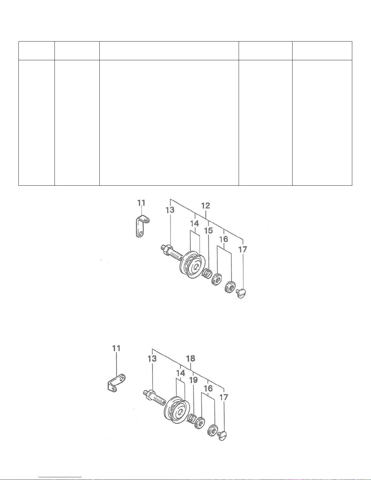
(1) THREAD STAND AND THREAD TENSION PARTS
11
245071
Thread Tension Eyelet
2
Ref. No. Part. No. Description Quantity Remarks
12
13
14
15
16
17
18
19
245081B
245081
065261
205091
245091
9/64S40011
245081A
245101
Thread Tension Assembly for Looper
Tension Post
Tension Disc
Tension Spring
Tension Nut
Screw for 245081
Thread Tension Assembly for Needle
Tension Spring
1
2
4
1
4
2
1
1
(13 – 17)
(13,14,16,17,19)
- 10 –
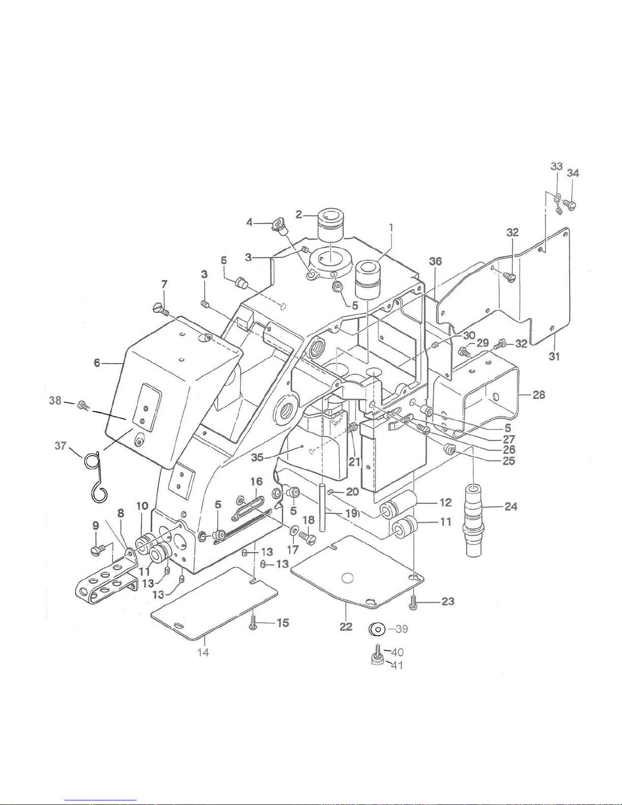
(2) COVERS, BUSHINGS AND OILING PARTS
- 11 –
 Loading...